

1081 Channel Amplifier
Including 3U and 7U Rack Options
User Guide
527-230
Issue 3
© 2000 AMS Neve plc own the copyright of all
information and drawings contained in this manual which
are not to be copied or reproduced by any means or
disclosed in part or whole to any third party without
written permission.
As part of our policy of continual product improvement,
we reserve the right to alter specifications without notice
but with due regard to all current legislation.
Disclaimer: The information in this manual has been
carefully checked and is believed to be accurate at the
time of publication. However, no responsibilty is taken by
us for inaccuracies, errors or omissions nor any liability
assumed for any loss or damage resulting either directly or
indirectly from use of the information contained within it.
HEAD OFFICE
AMS NEVE PLC BILLINGTON ROAD BURNLEY
LANCS BB11 5UB ENGLAND
TELEPHONE: +44 (0) 1282 457011 FAX: +44 (0) 1282 417282
LONDON OFFICE
TELEPHONE: +44 (0) 20 7916 2828 FAX: +44 (0) 20 7916 2827
NORTH AMERICAN OFFICES
AMS NEVE INC., NEW YORK
TEL: +1 (212) 965 1400 FAX: +1 (212) 965 3739
AMS NEVE INC., HOLLYWOOD
TEL: +1 (818) 753 8789 FAX: +1 (818) 623 4839
RUPERT NEVE CANADA INC., TORONTO
TEL: +1 (416) 365 3363 FAX: +1 (416) 365 1044
e-mail: enquiry@ams-neve.com
http://www.ams-neve.com

1081 Channel Amplifier
Contents
Introduction 1
Installation 1
Dimensions 2
Power Requirements 3
Phantom Power 4
Output Level Control 4
Amplifier Controls 5
EMI Filter Components 6
Rear Panel Views 7
Connector Details 8
Connector Details Continued 9
Specifications 10
Service Information 11
1081 Recall Sheet - Horizontal Module 12
1081 Recall Sheet - Vertical Module 13
User Guide Issue 3 Page i
1081 Channel Amplifier Introduction
Introduction
The 1081 channel amplifier was first produced in 1972 to provide the mic/line-amp and EQ
sections in Neve consoles such as the 8048. A look through the credits on today’s top selling CDs
will reveal that these vintage consoles are still widely used to great effect and that the 1081 module
has become a hugely popular design classic.This is why AMS Neve have resumed production of the
1081, using the original components and construction methods.
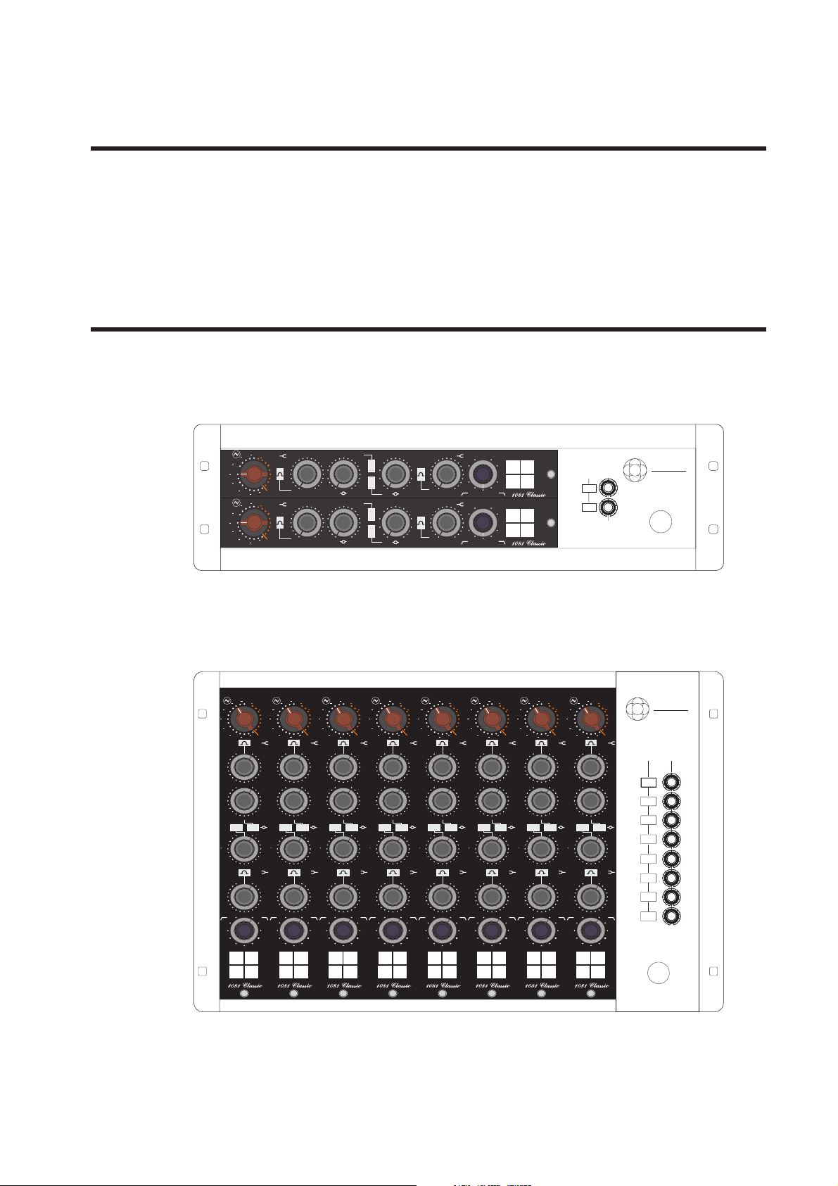
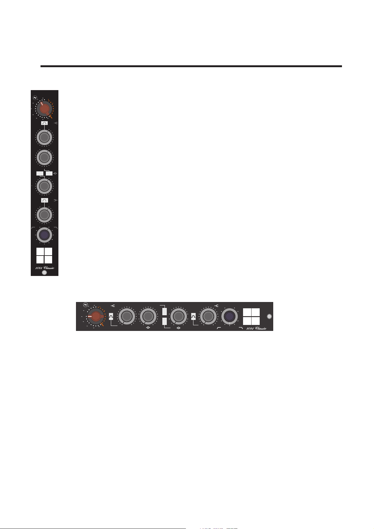
Installation
The 1081 is available as a stand-alone module, or in a choice of two housings that provide power
supply, phantom power switching for each module and connectors for balanced inputs (mic and
line) and outputs:
dB
80
70
20
60
50
40
MIC
30
10
20
dB
80
70
20
60
50
40
MIC
30
10
20
3
·3
3
·3
KHz
4
·7
2
10
68
·
0
10
+10
15
LINE
10
68
·
0
10
+10
15
LINE
·7
2
·2
1
·8
1·5
OFF
OFF
3
·3
3
·3
KHz
4
·7
2
·7
2
·2
1
·8
1·5
OFF
OFF
470
3·9
390
Hi
330
4
·7
Q
270
5
·6
Hi
220
6
·8
Q
OFF
8
·2
470
3·9
390
Hi
330
4
·7
Q
270
5
·6
Hi
220
6
·8
Q
OFF
8
·2
303
Hz
0
81
560
680
820
1000
1200
Hz
560
680
820
1000
1200
270
39
0
10
56
33
OFF
303
0
81
0
10
56
33
OFF
·
56
·
150
82
47
27
Hz
270
150
82
47
27
Hz
SOLO
8·2
EQ
PH
12
18
OFF
KHz
39
·
56
·
SOLO
8·2
EQ
PH
12
18
OFF
KHz
PHANTOM
+48V
CH1
CH2
+24V
OUTPUT
AMS
NEVE
1
2
MAINS
The 3U rack houses two modules mounted horizontally ina 19” rack-mounting unit. Therear panel
has XLRs for transformer balanced I/O and a 25-way ‘D’-type connector for solo and spare switch
contacts and unbalanced outputs plus an IEC connector for mains power.
dB dB dB dB dB dB dB dB
80 80 80 80 80 80 80 80
20 20 20 20 20 20 20 20
70 70 70 70 70 70 70 70
60 60 60 60 60 60 60 60
10 10 10 10 10 10 10 10
00000000
50 50 50 50 50 50 50 50
+10+10+10+10+10+10+10+10
40 40 40 40 40 40 40 40
LINE LINE LINE LINE LINE LINE LINE LINE
MIC MIC MIC MIC MIC MIC MIC MIC
30 30 30 30 30 30 30 30
10 10 10 10 10 10 10 10
20 20 20 20 20 20 20 20
OFF OFF OFF OFF OFF OFF OFF OFF
15 15 15 15 15 15 15 15
10 10 10 10 10 10 10 10
68
·
KHz KHz KHz KHz KHz KHz KHz KHz
4
·7
3
·3
OFF OFF OFF OFF OFF OFF OFF OFF
8
·2
6
·8
1·51·51·51·51·51·51·51·5
5
·6
1
·8
2
·2
4
·7
KHzKHzKHzKHzKHzKHzKHzKHz
3·9 3·9 3·9 3·9 3·9 3·9 3·9 3·9
2
·7
3
·3
HiQHiQHiQHiQHiQHiQHiQHiQ
HiQ HiQ HiQ HiQ HiQ HiQ HiQ HiQ
1111111122222222
0000000000000000
OFF OFF OFF OFF OFF OFF OFF OFF
11111111000000000000000000000000
2222222200000000
88888888
66666666
Hz Hz Hz Hz Hz Hz Hz Hz
Hz Hz Hz Hz Hz Hz Hz HzHz Hz Hz Hz Hz Hz Hz Hz
82 82 82 82 82 82 82 82
Hz Hz Hz Hz Hz Hz Hz Hz
000000002222222222222222
777777770000000022222222
8888888800000000
333333333333333300000000
55555555
6666666600000000
33333333
9999999900000000
44444444
7777777700000000
OFF OFF OFF OFF OFF OFF OFF OFF
33 33 33 33 33 33 33 33
56 56 56 56 56 56 56 56
111111110000000000000000
00000000
8888888811111111
333333330000000033333333
39
·
270 270 270 270 270 270 270 270
56
·
150 150 150 150 150 150 150 150
8·28·28·28·28·28·28·28·2
12 12 12 12 12 12 12 12
47 47 47 47 47 47 47 47
KHz KHz KHz KHz KHz KHz KHz KHz
18 18 18 18 18 18 18 18
27 27 27 27 27 27 27 27
OFF OFF OFF OFF OFF OFF OFF OFF
PH PH PH PH PH PH PH PH
EQ EQ EQ EQ EQ EQ EQ EQ
SOLO SOLO SOLO SOLO SOLO SOLO SOLO SOLO
68
·
4
·7
3
·3
8
·2
6
·8
5
·6
1
·8
2
·2
4
·7
2
·7
3
·3
39
·
56
·
68
·
4
·7
3
·3
8
·2
6
·8
5
·6
1
·8
2
·2
4
·7
2
·7
3
·3
39
·
56
·
68
·
4
·7
3
·3
8
·2
6
·8
5
·6
1
·8
2
·2
4
·7
2
·7
3
·3
39
·
56
·
68
·
4
·7
3
·3
8
·2
6
·8
5
·6
1
·8
2
·2
4
·7
2
·7
3
·3
39
·
56
·
68
·
4
·7
3
·3
8
·2
6
·8
5
·6
1
·8
2
·2
4
·7
2
·7
3
·3
39
·
56
·
68
·
4
·7
3
·3
8
·2
6
·8
5
·6
4
·7
3
·3
3
·3
8
·2
6
·8
5
·6
1
·8
2
·2
4
·7
2
·7
3
·3
39
·
56
·
68
·
4
·7
1
·8
2
·2
2
·7
39
·
56
·
+48V
+24V
AMS
NEVE
PHANTOM OUTPUT
CH1
CH2
CH3
CH4
CH5
CH6
CH7
CH8
MAINS
1
2
3
4
5
6
7
8
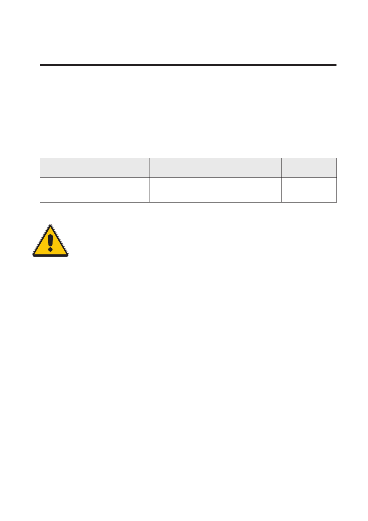
The 7U rack houses 8 modules vertically in a 19” rack-mounting unit. The rear panel has XLRs for
transformer balanced I/O and a 25-way ‘D’-type connector for solo and spare switch contacts and
unbalanced outputs plus an IEC connector for mains power.
User Guide Issue 3 Page 1
1081 Channel Amplifier Dimensions
Dimensions
Stand-alone Module
Dimensions: Front panel 45mm x 305 mm (1.8 inches x 12 inches).
Approx 300mm (12 inches) deep behind the front panel.
Approx. Weight: 3kg (6.6 lbs)
Rack Data
19" Rack Mounting U Depth
mm (inches)
2 Module Version 3 400 134 (5¼) 17 (37) *
8 Module Version 7 400 311 (12¼) 46 (101) *
Height
mm (inches)
Approx. Weight
kg (lbs)
* Fully populated rack
The 7U unit is heavy (over 20kg) and should be handled by two persons.
User Guide Issue 3 Page 2
1081 Channel Amplifier Power Requirements
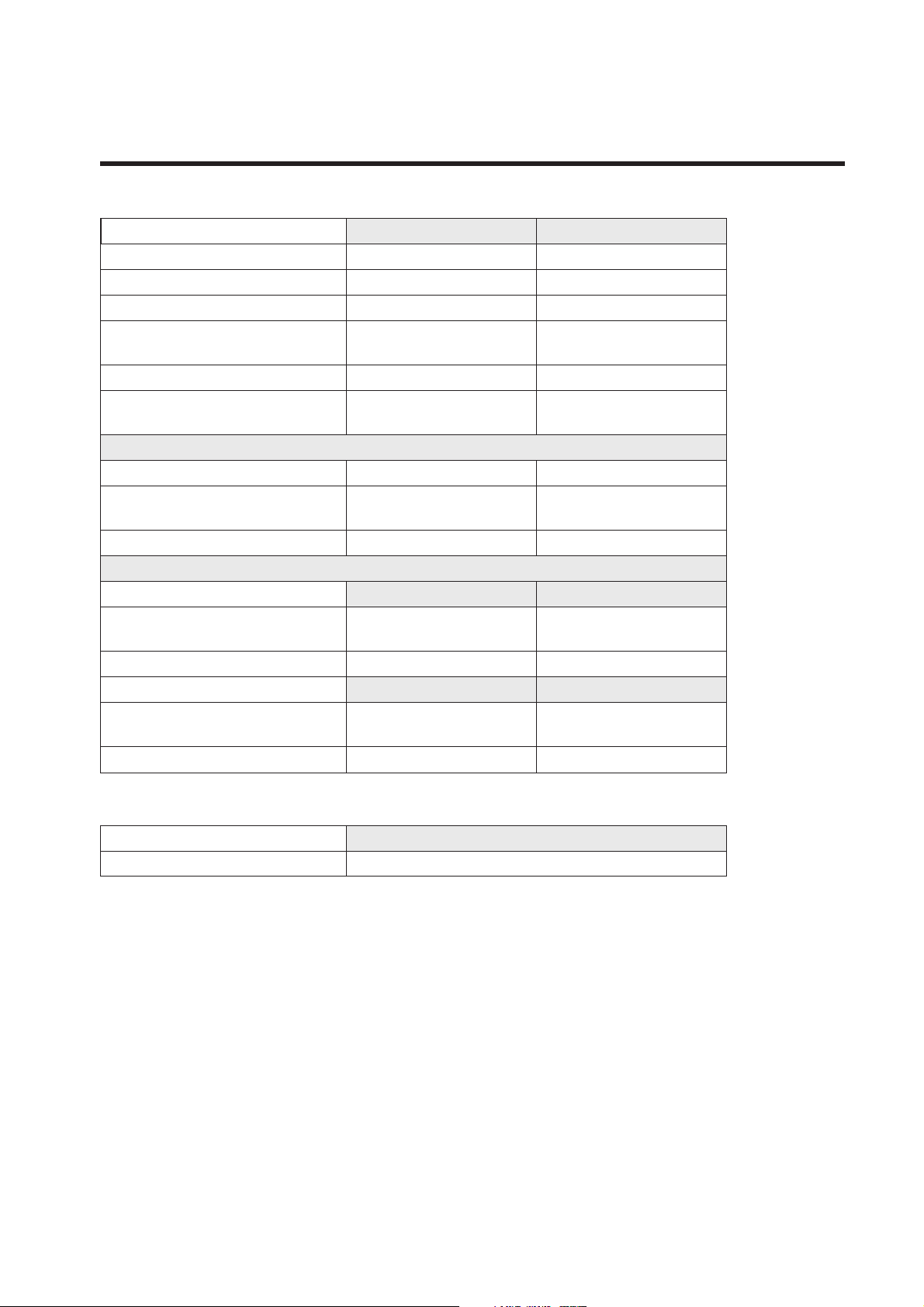
Power Requirements
3U 7U
Rated Voltage 100-230V AC 100-230V AC
Rated Frequency 50-60 Hz 50-60Hz
Rated Current 0.5A Max 0.8A Max
Surge Current (In Rush) Cold
Surge Current (In Rush) Hot
Earth Leakage Current Approx 1.2mA Approx 1.3mA
Warning for High Earth Leakage
Current Required
Primary Protection Fuse:
Operating Voltage 100-230V AC 100-230V AC
Fuse Rating and Type T1.6A H 250V
Location IEC Mains connector IEC Mains connector
Secondary Protection Fuse:
Output Voltage 24V DC 24V DC
Fuse Rating and Type T 1.0A L 250V
Location F1 on SZN825-058 F1 on SZN825A058
Output Voltage 48V DC 48V DC
Fuse Rating and Type T 500mA L 250V
Location F2 on SZN825-058 F2 on SZN825A058
31.0A
33.0A
NO NO
20mm x 5mm CERAMIC
20mm x 5mm GLASS
20mm x 5mm GLASS
31.0A
33.0A
T1.6A H 250V
20mm x 5mm CERAMIC
T 2.0A L 250V
20mm x 5mm GLASS
T 500mA L 250V
20mm x 5mm GLASS
Stand-alone 1081 Module
Power 192mA at 24V DC. Negative Earth
Mains Supply (rack units)
The power supply unit is a universal input type therefore no mains operating voltage setting is
required.
The mains switch on the front panel of the 3U and 7U rack units is non-illuminating.
The CH (chassis) and 0V Link should be connected or instability may result.
User Guide Issue 3 Page 3

1081 Channel Amplifier Phantom Power
Mains Fuse (rack units)
The mains fuse is located in the IEC mainsinput connector on the rear ofthe 3U and 7U rack units.
Secondary Protection Fuses (rack units)
Secondary protection fuses for the 24V and 48V supplies are located behind the front panel on the
power supply filter PCB SZN825-058 in both 3U and 7U rack units.
DC Power Supply Indicators (rack units)
The red LED on the front panel of both 3U and 7U rack units indicates +24V power healthy when
illuminated.
The green LED on the front panel of both 3U and 7U rack units indicates +48V power healthy when
illuminated.
Phantom Power
Phantom power can be supplied toeach module by pressing the phantom power switch on the front
panel of the 3U or 7U rack. The LED in the switch will illuminate confirming that phantom power is
supplied.
Output Level Control
Each channel has an independent Output Level Control. The control is post-input, post-EQ and
pre-output. This control allows the input and EQ to operate at a higher level and then for the signal
to be returned to a normal operating level at the output.
When the Output Control is fully clockwise the output gain is unity. The output is 10dB down with
the control in the mid-position.
User Guide Issue 3 Page 4
1081 Channel Amplifier Amplifier Controls
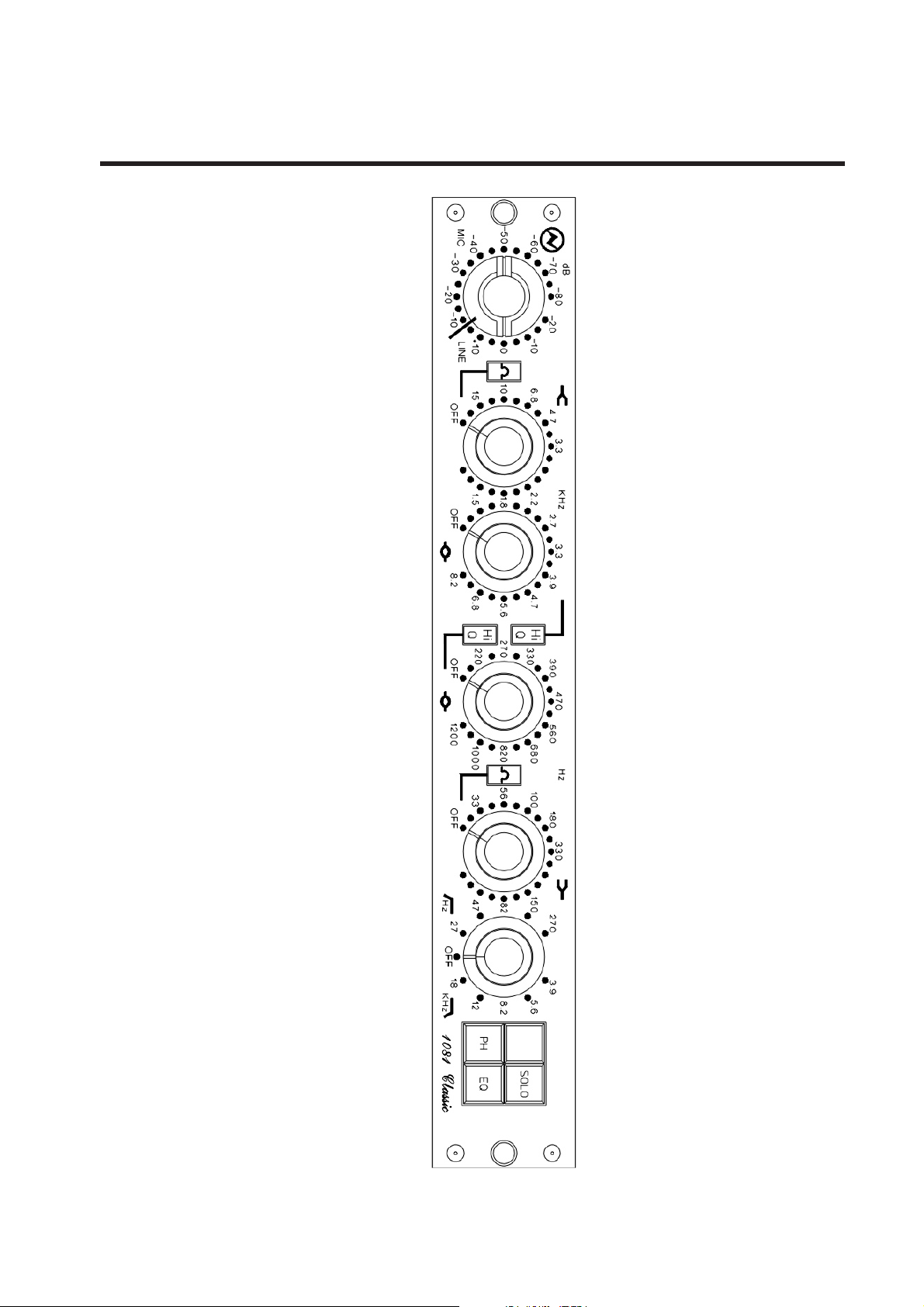
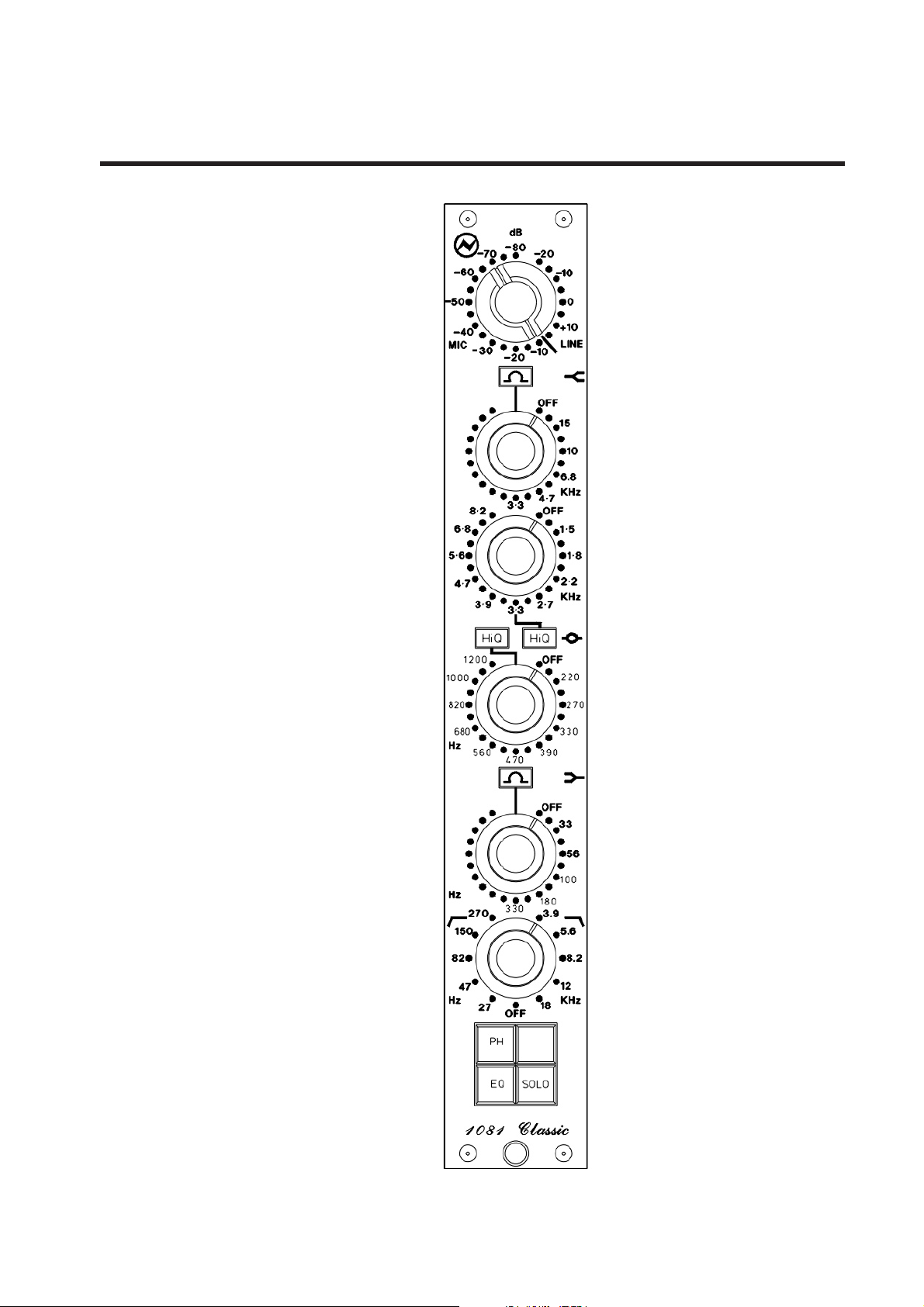
Amplifier Controls
dB
80
20
70
60
50
40
MIC
6·8
5·6
4·7
1000
20
8
680
Hz
HzHz
82
47
Hz
10
0
+10
LINE
30
10
20
OFF
15
10
·
68
KHz
4·7
3·3
OFF
8·2
1·5
1·8
2·2
KHz
3·9
2·7
3·3
HiQ
HiQ
12
00
OFF
022
702
330
5
60
390
470
OFF
33
56
100
0
81
303
39·
270
56·150
8·2
12
KHz
18
27
OFF
PH
EQ
SOLO
H.F. Controls: 5 switched frequencies, shelving or peaking curve, continuously
variable 18dB cut or boost.
H.F. Presence: 10 switched frequencies with continuously variable 18dB cut or
boost, high or low Q selection.
L.F. Presence: 10 switched frequencies with continuously variable 18dB cut or
boost, high or low Q selection.
L.F. Controls: 5 switched frequencies, shelving or peaking curve, continuously
variable 18dB cut or boost.
H.P. Filter: 5 switched frequencies with slope of 18dB per octave.
L.P. Filter: 5 switched frequencies with slope of 18dB per octave.
PH Button: Gives 180° phase change at the balanced output.
EQ Button: Selects equalisation in or out of circuit.
SOLO Button: Selects channel unbalanced output and closing switch contact.
Spare Button: Switches external device as required.
dB
80
70
20
60
50
40
MIC
10
0
+10
LINE
30
10
20
3
·3
4
·7
·
68
10
15
OFF
3
·3
KHz
3·9
2
·7
2
·2
1
·8
1·5
4
6
OFF
8
·2
470
560
390
Hi
330
·7
Q
270
5
·6
Hi
220
·8
Q
820
1000
OFF
1200
303
Hz
0
81
0
680
10
56
33
OFF
39
·
270
56
150
82
47
Hz
·
SOLO
8·2
EQ
PH
12
18
27
OFF
KHz
User Guide Issue 3 Page 5

1081 Channel Amplifier EMI Filter Components
EMI Filter Components
Jumpers may be fitted on the SUN870-081 I/O boards to allow the EMI filtering (three terminal
capacitors and common mode inductors) to be ‘removed’ from the signal path. This may be
desirable for those seeking sonic purity. However it must be noted that the immunity of the product
to external RF fields could suffer, and if thisis the case then the jumperlinks should be removed.
The individual 1081 modules are offered for inclusion in the customers own housings. As such no
claim is being made regarding the immunity of these units. This will be principally governed by the
type of cabling, connectors and enclosure used. The use of screened cables and connectors is
recommended for all connections. Tests have shown that no problems with emissions as defined in
EMC standards should be present with these units.
User Guide Issue 3 Page 6

1081 Channel Amplifier Rear Panel Views
Rear Panel Views
ACM AINSI/P
MIC 1 LINE 1 O/P 1
CH 0V
MIC 8 MIC 7 MIC 6 MIC 5 MIC 4 MIC 3 MIC 2 MIC 1
LINE 8
O/P 8
MIC 2 LINE 2 O/P 2
LINE 6LINE 7 LINE 5
O/P 6O/P 7 O/P 5
AUXILARY
LINE 3LINE 4 LINE 2
O/P 3O/P 4 O/P 2
LINE 1
O/P 1
AC MAINS I/P
CH 0V
AUXILARY 7-8 AUXILARY 5-6 AUXILARY 3-4 AUXILARY1- 2
User Guide Issue 3 Page 7
1081 Channel Amplifier Connector Details
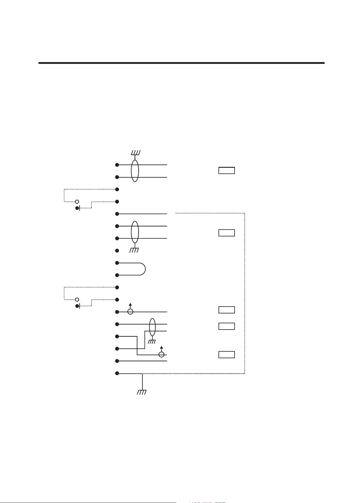
Connector Details
1081 Stand-alone
Wiring to 18 way Free Plug
Spare
Solo
A
B
C
Spare Switch Contact
D
E
F
H
J
K
L
M
Solo Switch Contact
N
P
R
S
T
U
0V
Link
Hi
Mic I/P
Lo
0V
Hi
Line I/P
Lo
Unbalanced O/P
Hi
BAL O/P
Lo
0V
Solo O/P (unbalanced)
+24V at 192mA
0dBu
0dBu
Technical
Earth Link
-10dBu
0dBu
-10dBu
V
User Guide Issue 3 Page 8

1081 Channel Amplifier Connector Details Continued
2
2
2
2
7
8
Connector Details Continued
Rear of 1081 2 Module (3U) and 8 Module (7U) Racks
25 way D Auxiliary and XLR Wiring
25 way D-Type
Wiring View
1
NC
14
NC
Chassis Earth
Unbalanced 0V
Solo 1
Spare 1
Chassis Earth
Spare 2
Solo 2
Unbalanced 0V
Chassis Earth
2
15
3
16
4
17
5
18
6
19
7
20
8
21
9
22
10
23
11
24
12
25
NC
13
NC
Unbalanced O/P
Chassis Earth
Solo O/P (unbalanced)
Solo Switch Contacts CH1
Spare Switch Contacts CH1
Spare Switch Contacts
Solo Switch Contacts
Solo O/P (unbalanced)
Chassis Earth
Unbalanced O/P
-10dBu
-10dBu
-10dBu
-10dBu
For the 8 Module Rack :
CH 1
CH 1
CH
CH
CH
CH
CH1 is CH1, CH 3, CH 5 or CH
CH2isCH2,CH4,CH6orCH
XLR
Wiring View
Mic/Line I/P (Balanced)
Hi
Lo
Plug
12
3
O/P (Balanced)
Socket
12
3
Hi
Lo
User Guide Issue 3 Page 9

1081 Channel Amplifier Specifications
Specifications
Microphone Input: Zin 300 or 1200 ohms switched,
gain +80 to +10 dB in 5dB steps.
Line Input: Zin 10k ohms bridging, gain +20 to -15dB in 5dB steps.
Both inputs are balanced and earth-free.
Outputs: Max +26dB into 600 ohms. Zout 75 ohms ±5% @ 1kHz,
balanced and earth-free. An unbalanced output 8dB below
the level of the balanced output is also provided.
Distortion: Not more than 0.07% for +20dBm output from 50Hz to 15kHz.
Frequency Response: ±0.5dB from 20Hz to 20kHz. -3dB at 7Hz and 35kHz.
Noise: Output noise better than -42dBm from Zin 1200 ohms and
-80dB input, giving an equivalent noise of -125dBm referred to
600 ohms input impedance fed from 100 ohms. Output noise
better than - 80dBm at all line input levels.
User Guide Issue 3 Page 10

1081 Channel Amplifier Service Information
Service Information
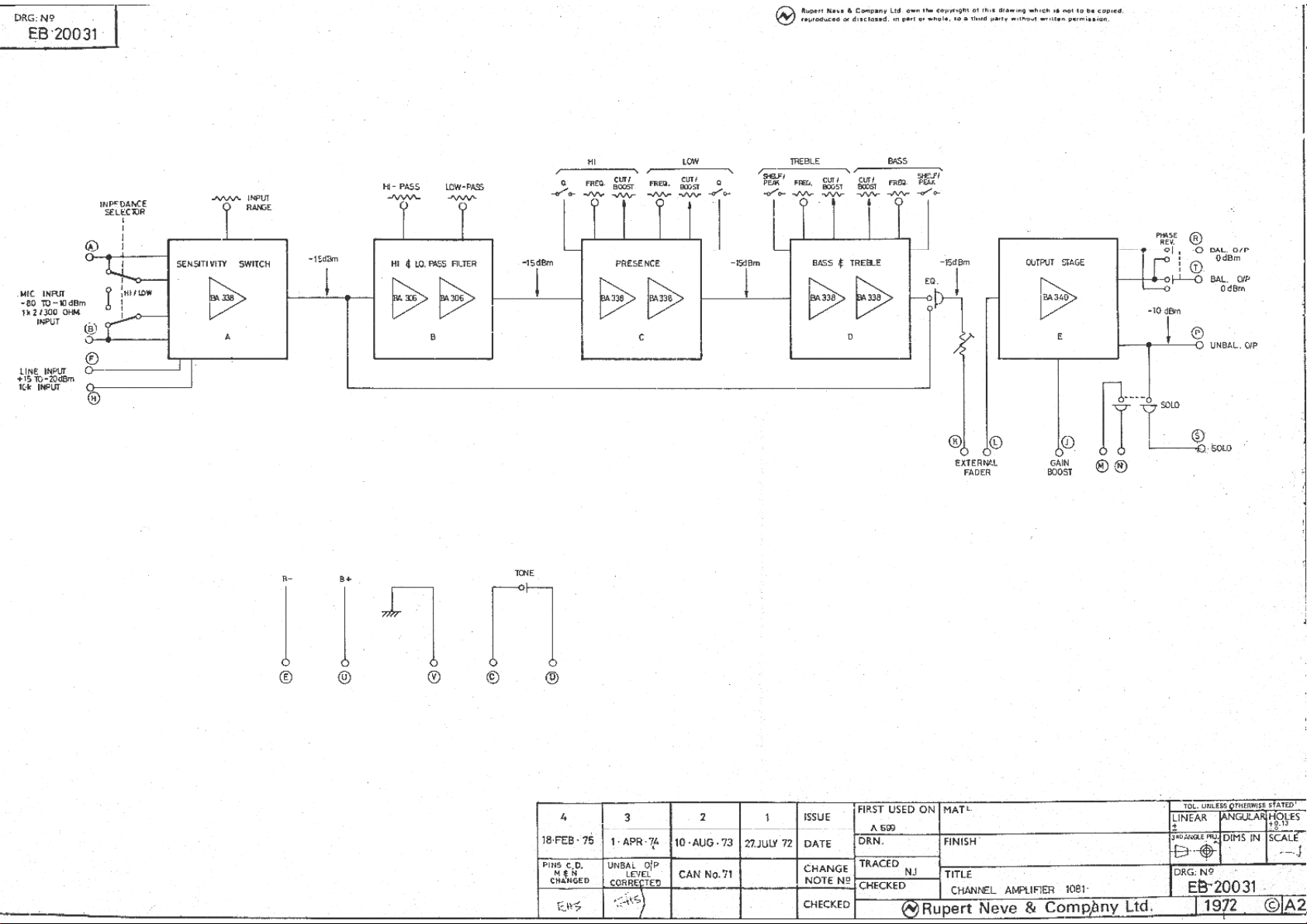
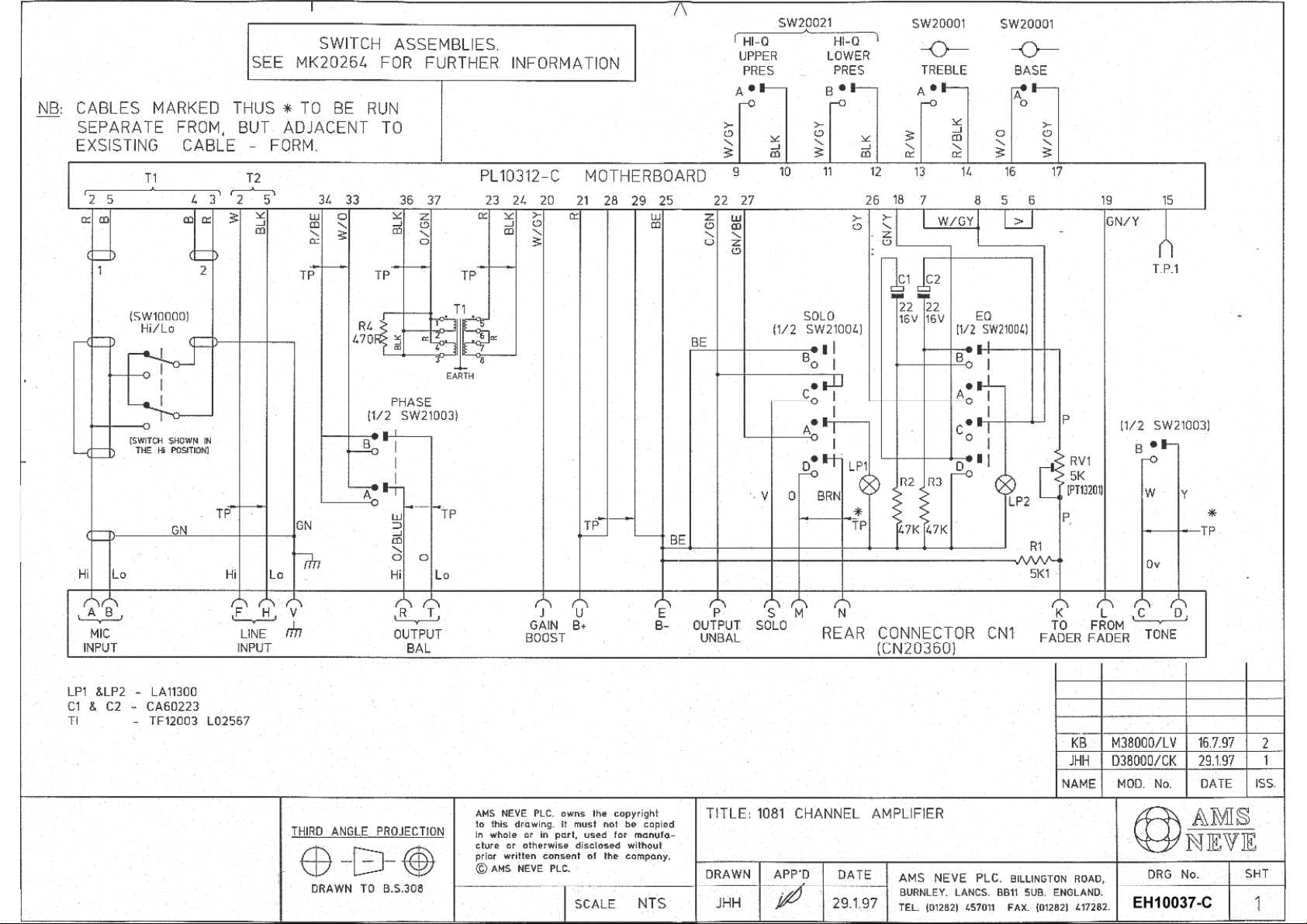
Schematic Drawing index
PL31081- Channel Amplifier Horizontal and Vertical module versions:
PL31081-C Channel Amplifier
PL10306-C Dual Voltage Follower
PL10312-C Channel Amplifier Motherboard
PL10338-C High Gain Amplifier
PL10340-C Output Amplifier
PL20046 Sensitivity Switch
PL20047 Treble Switch Assembly
PL20048/4 Upper Presence Switch Assembly
PL20048/5 Lower Presence Switch Assembly
PL20049 LP/HP Filter Switch Assembly
PL20050 Bass Switch Assembly
AM3631 - 3U Rack:
AM3631 2 CH 1081 Mainframe Assembly Detail
SZN825-058 PSU Filter PCB
SSN818-036 0V Stud Filter PCB
SUN870-081 2CH I/P O/P Backplane
SYN824-128 2 Switch Phantom Power PCB
NN3726 Chassis Cable Assy
AM3630 - 7U Rack:
AM3630 8 CH 1081 Mainframe Assembly Detail
SZN825A058 PSU Filter PCB
Same as the 3U Rack
User Guide Issue 3 Page 11
1081 Channel Amplifier 1081 Recall Sheet - Horizontal Module
1081 Recall Sheet - Horizontal Module
User Guide Issue 3 Page 12
1081 Channel Amplifier 1081 Recall Sheet - Vertical Module
1081 Recall Sheet - Vertical Module
User Guide Issue 3 Page 13


Title: 2 Channel 1081 Chassis Wiring Schedule Nr: AM3631
Issue: 3
CABLE FROM:- ROUTING TO:-
Code Type Colour Pin Connector Location Signal Length Comment Pin Connector Location
310-166 32/0.2 Green/Yellow E 330-119 IEC Stud 330-454 Chassis Safety
310-183 24/0.2 Green/Yellow E 330-069 PSU1 Stud 330-454 Chassis
310-183 24/0.2 Green/Yellow E 330-069 PSU2 Stud 330-454 Chassis
310-132 24/0.2 Brown L 330-119 IEC 13 Switch
Blue N 330-119 IEC 23 Switch
310-132 24/0.2 Brown L 330-471(1of2) PSU1 14 Switch
Blue N 330-471(1of2) PSU1 24 Switch
310-132 24/0.2 Brown L 330-471(2of2) PSU1 L 330-069 PSU2
Blue N 330-471(2of2) PSU1 N 330-069 PSU2
310-166 32/0.2 Green/Yellow Ch 330-069 SSN818A036 Stud 330-454 Chassis
310-074 24/0.2 Red +24V 330-069(1of2) PSU1 Twist 1 420-712 CN1
310-072 24/0.2 Black -0V 330-069(1of2) PSU1 together 2 SZN825-058
310-048 16/0.2 Red +24V 330-069(2of2) PSU1 Twist X2 Switch
310-046 16/0.2 Black -0V 330-069(2of2) PSU1 together X1 Switch
310-075 24/0.2 Orange + 330-069 PSU2 Twist 3 CN1
310-072 24/0.2 Black - 330-069 PSU2 together 4 SZN825-058
310-074 24/0.2 Red 1 420-712 CN2 Twist +24V WA17103 1081CN PNL
310-072 24/0.2 Black 2 SZN825-058 together 0VA WA17103
310-072 24/0.2 Black J1 SSN818A036 0VA WA17103
310-048 16/0.2 Red +24V WA17103 1081CN PNL U 1081 CN1
U 1081 CN2
310-046 16/0.2 Black 0VA WA17103 1081CN PNL E 1081 CN1
E 1081 CN2
310-033 7/0.2 Green E1 SUN870-081 2cm Chassis 330-006
310-033 7/0.2 Green E2 Channel 1&2 2cm Chassis 330-006
13 December, 2001 Page:
3


Title: 8 Channel 1081 Chassis Wiring Schedule Nr: AM3630
Issue: 4
CABLE FROM:- ROUTING TO:-
Code Type Colour Pin Connector Location Signal Length Comment Pin Connector Location
310-166 32/0.2 Green/Yellow E 330-119 IEC 25cms Stud 330-454 Chassis Safety
310-183 24/0.2 Green/Yellow E 330-069 PSU1 40cms Stud 330-454 Chassis
310-183 24/0.2 Green/Yellow E 330-069 PSU2 40cms Stud 330-454 Chassis
310-132 24/0.2 Brown L 330-119 IEC 58cms 13 Switch
Blue N 330-119 IEC 58cms 23 Switch
310-132 24/0.2 Brown L 330-471(1of2) PSU1 80cms 14 Switch
Blue N 330-471(1of2) PSU1 80cms 24 Switch
310-132 24/0.2 Brown L 330-471(2of2) PSU1 15cms L 330-069 PSU2
Blue N 330-471(2of2) PSU1 15cms N 330-069 PSU2
310-166 32/0.2 Green/Yellow Ch 330-069 SSN818A036 23cms Stud 330-454 Chassis
310-074 24/0.2 Red +24V 330-069(1of2) PSU1 90cms Twist 1 420-712 CN1
310-072 24/0.2 Black - 0V 330-069(1of2) PSU1 90cms together 2 SZN825-058
310-048 16/0.2 Red +24V 330-069(2of2) PSU1 90cms Twist X2 Switch
310-046 16/0.2 Black -0V 330-069(2of2) PSU1 90cms together X1 Switch
310-075 24/0.2 Orange +48V 330-069 PSU2 1mtr Twist 3 CN1
310-072 24/0.2 Black - 0V 330-069 PSU2 1mtr together 4 SZN825-058
310-074 24/0.2 Red 1 420-712 CN2 80cms Twist +24V WA17103 1081CN PNL
310-072 24/0.2 Black 2 SZN825-058 82cms together 0VA WA17103
310-072 24/0.2 Black J1 SSN818A036 58cms 0VA WA17103
310-048 16/0.2 Red +24V WA17103 1081CN PNL 8cms U 1081 CN1-4
8cms U 1081 CN5-8
310-046 16/0.2 Black 0VA WA17103 1081CN PNL 8cms E 1081 CN1-4
8cms E 1081 CN5-8
310-033 7/0.2 Green E1 SUN870-081 2cm Chassis 330-006
310-033 7/0.2 Green E2 Channel 1&2 2cm Chassis 330-006
310-033 7/0.2 Green E1 SUN870-081 2cm Chassis 330-006
13 December, 2001 Page:
3

Title: 8 Channel 1081 Chassis Wiring Schedule Nr: AM3630
Issue: 2
CABLE FROM:- ROUTING TO:-
Code Type Colour Pin Connector Location Signal Length Comment Pin Connector Location
310-033 7/0.2 Green E2 Channel 3&4 2cm Chassis 330-006
310-033 7/0.2 Green E1 SUN870-081 2cm Chassis 330-006
310-033 7/0.2 Green E2 Channel 5&6 2cm Chassis 330-006
310-033 7/0.2 Green E1 SUN870-081 2cm Chassis 330-006
310-033 7/0.2 Green E2 Channel 7&8 2cm Chassis 330-006
13 December, 2001 Page:
4


 Loading...