

1073 BUILDING GUIDE
VERSION 1.1
BY MATHIEU CANTIN
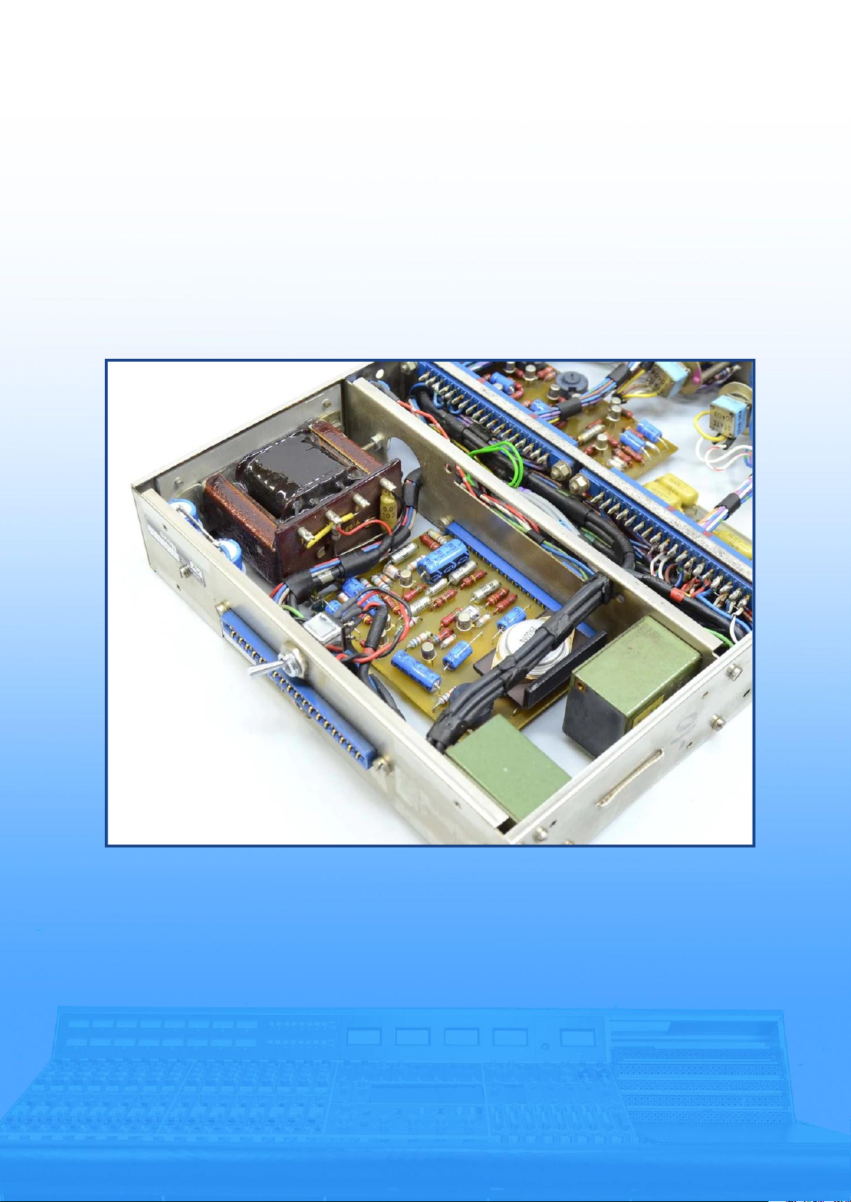
Photo by BAKU Pro Audio ©

1073 Building Guide
TABLE OF CONTENTS
Version 1.1 1
Introduction ..................................................................................................................... 2
Materials ......................................................................................................................... 3
B.O.M. .............................................................................................................................. 9
Assembly
● Transformers ....................................................................................................... 24
● Gain Switch .......................................................................................................... 25
● EQL/Phase Switch ............................................................................................... 28
● Impedance Switch ............................................................................................... 29
● High Pass Filter Switch ........................................................................................ 30
● Low Freq. Switch ................................................................................................. 31
● Presence Switch .................................................................................................. 34
● PC Pins or Cable Clamps? .................................................................................... 35
Edge connectors Assembly (Cable Clamp Version)
● B284, B182, B211, B205, B283 ............................................................................ 36
● Connections Between Edge Connectors ............................................................... 40
● Wiring the EQ Switches ........................................................................................ 43
● Wiring the Gain Switch ......................................................................................... 47
● Wiring the Line I/P Transformer ........................................................................... 49
● Wiring the Mic I/P Transformer ............................................................................ 50
● Wiring the B283 ................................................................................................... 50
● Wiring the C7 and C8 Capacitors .......................................................................... 52
● Wiring the EQL/Phase Switch ............................................................................... 53
● Wiring the B284 ................................................................................................... 54
● Wiring the C4 and C10 Capacitors ........................................................................ 55
● Wiring the O/P Transformer ................................................................................. 56
● Wiring the Main Edge Connector .......................................................................... 56
Edge Connectors Assembly (PC Pins Version)
● B284, B182, B211, B205, B283 ............................................................................ 58
● Connections Between Edge Connectors ............................................................... 61
● Wiring the EQ Switches ........................................................................................ 64
● Wiring the Gain Switch ......................................................................................... 68
● Wiring the Line I/P Transformer ........................................................................... 70
● Wiring the Mic I/P Transformer ............................................................................ 71
● Wiring the B283 ................................................................................................... 72
● Wiring the C4, C5, C7, C8 and C10 Capacitors ...................................................... 73
● Wiring the EQL/Phase Switch ............................................................................... 75
● Wiring the O/P Transformer ................................................................................. 77
● Wiring the Main Edge Connector .......................................................................... 78
PCB Assembly .............................................................................................................. 79
Biasing the BA283 ........................................................................................................ 83
Going the Extra Mile ..................................................................................................... 84

1073 Building Guide
INTRODUCTION
Version 1.1 2
This is an in depth guide on how to build your own 1073 channel amplifier in its
original 80 series format. I have worked many months to gather all the information I
could possibly find to make a complete wiring guide as well as an extensive list of
materials needed to make either a vintage or a modern AMS reproduction of the
1073. This is not a standalone unit with XLR connectors. You need a proper rack to
connect and power these modules.
This guide is aimed to be a support tool in addition to the “1073 user manual” which
has all the original schematics.
I wanted to make this guide because I felt very grateful for all the information that I
was able to find online, especially on GroupDIY. This is my way of giving back to the
DIY community. Hopefully it will provide the tools and courage to beginners who
could feel intimidated by this legendary build.
Don’t forget to quadruple check every decision you make and most importantly, have
fun!
Disclaimer
First and foremost I am a french speaking Canadian so please forgive me if I have
some weird sentence structures. I am only an amateur engineer since I don’t have an
audio electrical-engineering degree. To make the wiring guide I reverse engineered
the whole thing using pictures of vintage modules as well as the recent AMS reissue
while following the schematics. I made a complete 3D model to make sure all the
wiring plans I made actually made sense. I do believe I got everything right on this
one but I could be wrong.
If you see a mistake or you have information you feel should be added to this guide
please email me at math.cantin@gmail.com or message my profile MathCantin on the
GroupDIY forum and I will modify the document ASAP.
1073 Building Guide
MATERIALS
Version 1.1 3
This section is a deep dive into the specifics of each part that are needed to
assemble a complete 1073. I cover mostly unique parts here since most of the
mundane parts like resistors don’t need much covering.
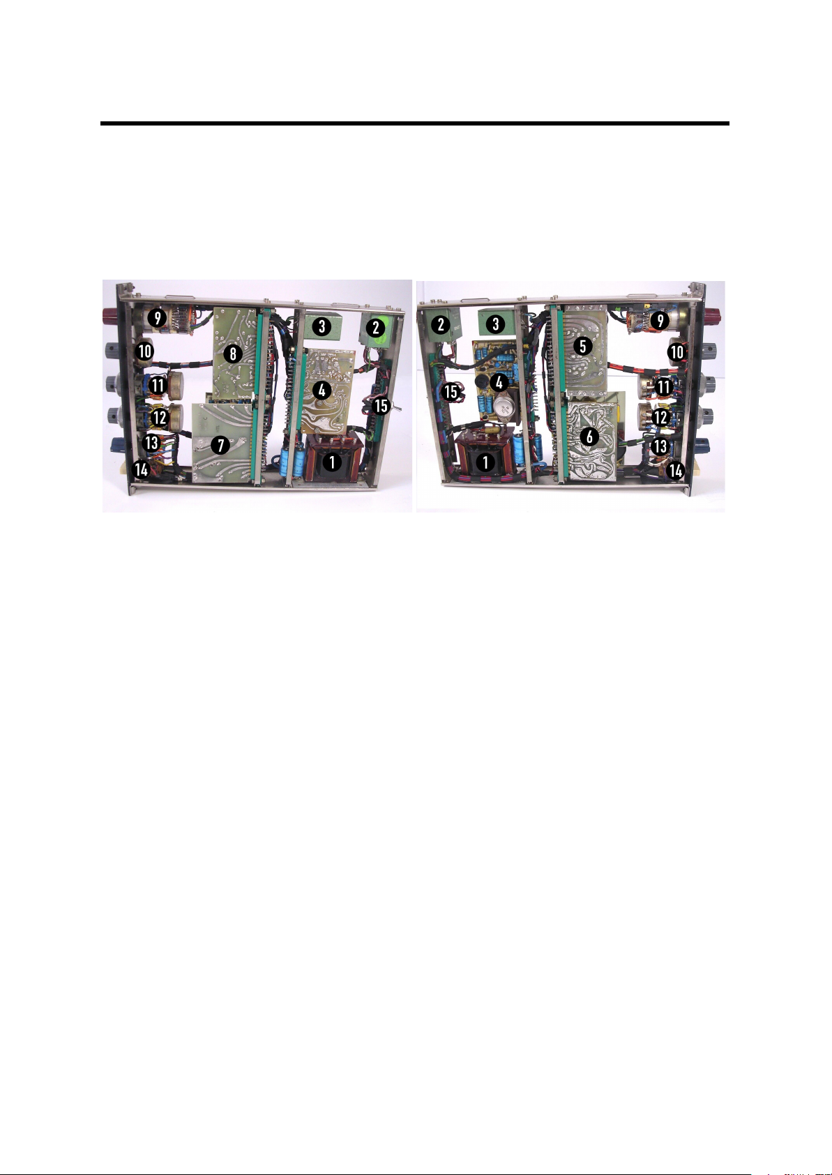
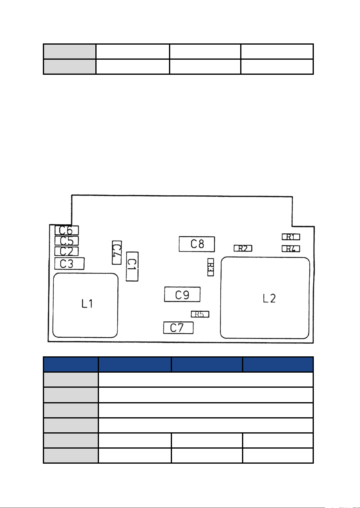
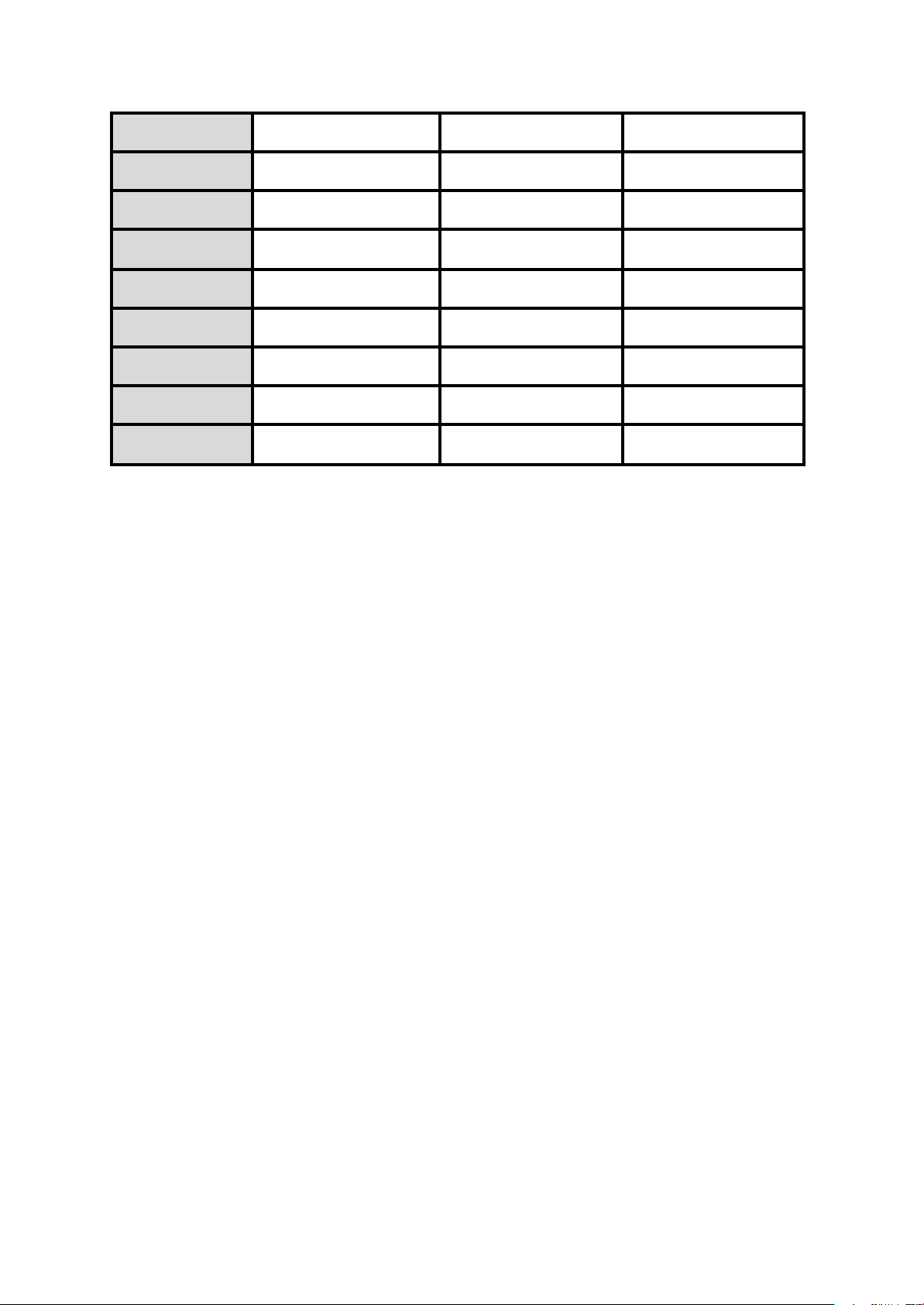
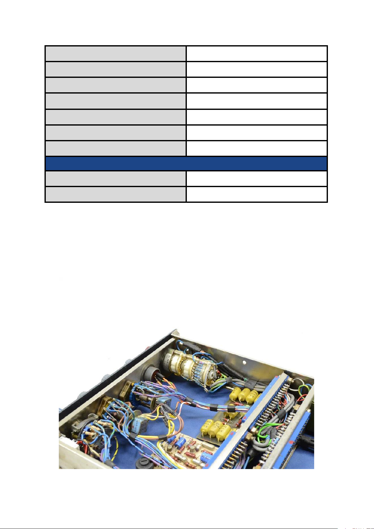
Layout
Here’s two pictures detailing the insides of the module with the unique parts
numbered.
1. Output transformer 2. Mic. input transformer
3. Line input transformer 4. BA283
5. B205 6. B284
7. B182 8. B211
9. Gain Switch 10. High Frequency EQ
11. Presence EQ 12. Low Frequency EQ
13. High Pass Filter EQ 14. EQL / Phase Switch
15. Impedance Switch
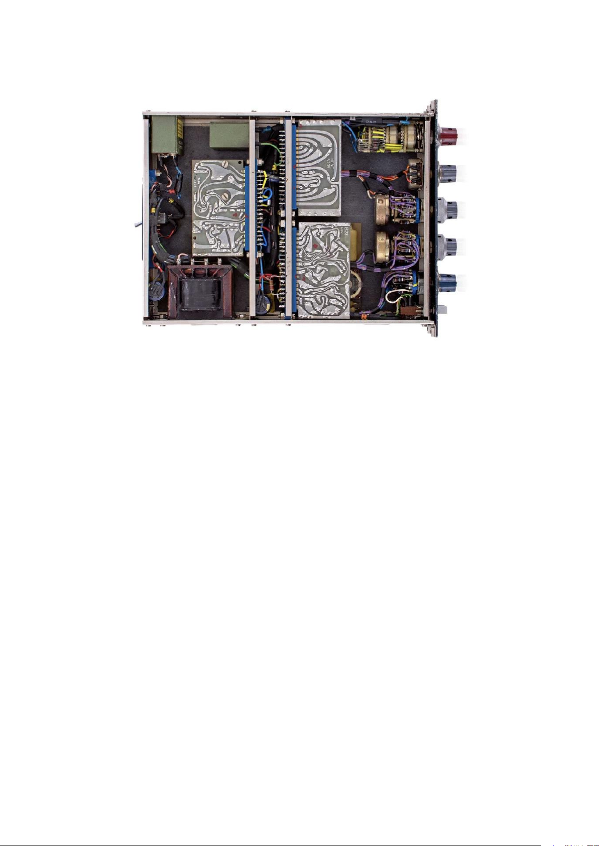
Please note that the BA283 can be installed this way or on the other slot over it, if
rotated 180°. Like the example below.
1073 Building Guide
CASE
Version 1.1 4
Photo by Retro Gear Shop ©
One of the most important steps of this build might be the most complicated one.
Since there’s no real constant supply of 80 series cases going around you might have
a hard time finding one. Even when there is some for sale they might have
differences that will influence the build. Notably and not inclusively, the middle
section where the BA283 is attached, the impedance switch hole and the second
front panel where the EQL and PHASE push-button switch is attached. I will go into
details about the middle section a bit later in the guide.
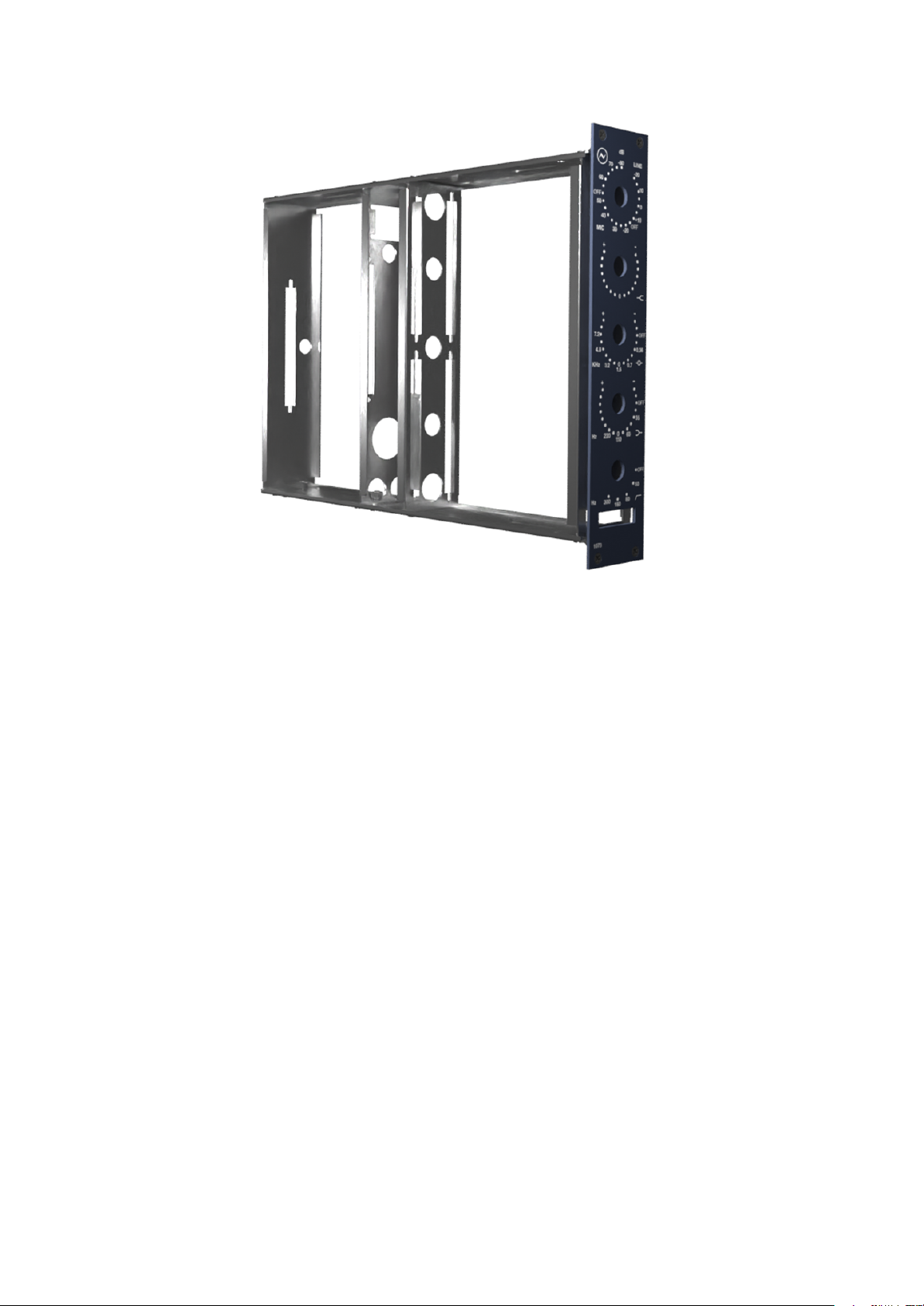
The case is an assembly of 8 nickel-plated steel panels and 1 aluminum powder
coated front plate. Here is a picture of an assembled case without the side panels::
The side panels are covered with either colored kraft paper (I’ve seen black and blue
used) or some thin rubber sheet to help prevents shorts.
1073 Building Guide
PCB’s
Version 1.1 5
I have found cases for sale on Ebay and also through a seller GroupDIY. The one I
purchased through Ebay came with the pushbutton switch and the caps but had no
bracket for the LO 1166 and the one I purchased through a seller on GroupDIY had no
push button switch included but had the pushbutton caps and the LO 1166 bracket.
So depending on who you buy it from you might have to buy or build yourself some
parts to be able to finalize your module. I highly recommend messaging the seller to
know what is included with the chassis.
You need 5 different PCB’s to fill out your module. BA283, B205, B284, B182 AND
B211. They are absolutely vital to this build and like the chassis there is no constant
supply of them. They are simple one sided PCBs with all the traces on one side so if
you want you could probably have them made or build them yourselves. You might be
able to find reproduction through GroupDIY, Ebay or some other sellers. I personally
bought some on AVDAUDIO’s website and through Sasarist on GroupDIY.
ATTENTION: Some vintage parts like capacitors have large leads that might not fit
the PCB holes. If that happens make sure the PCB trace is big enough for the hole to
be enlarged, you don't want to drill right through the trace. Just use a small hand drill
with tiny bits until your leads fit right in.
1073 Building Guide
SCREWS
Version 1.1 6
The panels in the original modules were screwed together with 6BA machine cheese
head slotted screws and the front panel was held with 6BA flat head black
countersunk machine screws with an .050” socket.
BA screws are an old set of threads commonly used for small instruments and
modeling. They are hard to find since they are now mostly considered obsolete.
Most modern recreation of the chassis are not using the BA screw threads since they
are hard to source. If you’re looking to replace 6BA screws you should be able to use
UNF 4-48 screw threads because the thread is only 0.002” different.
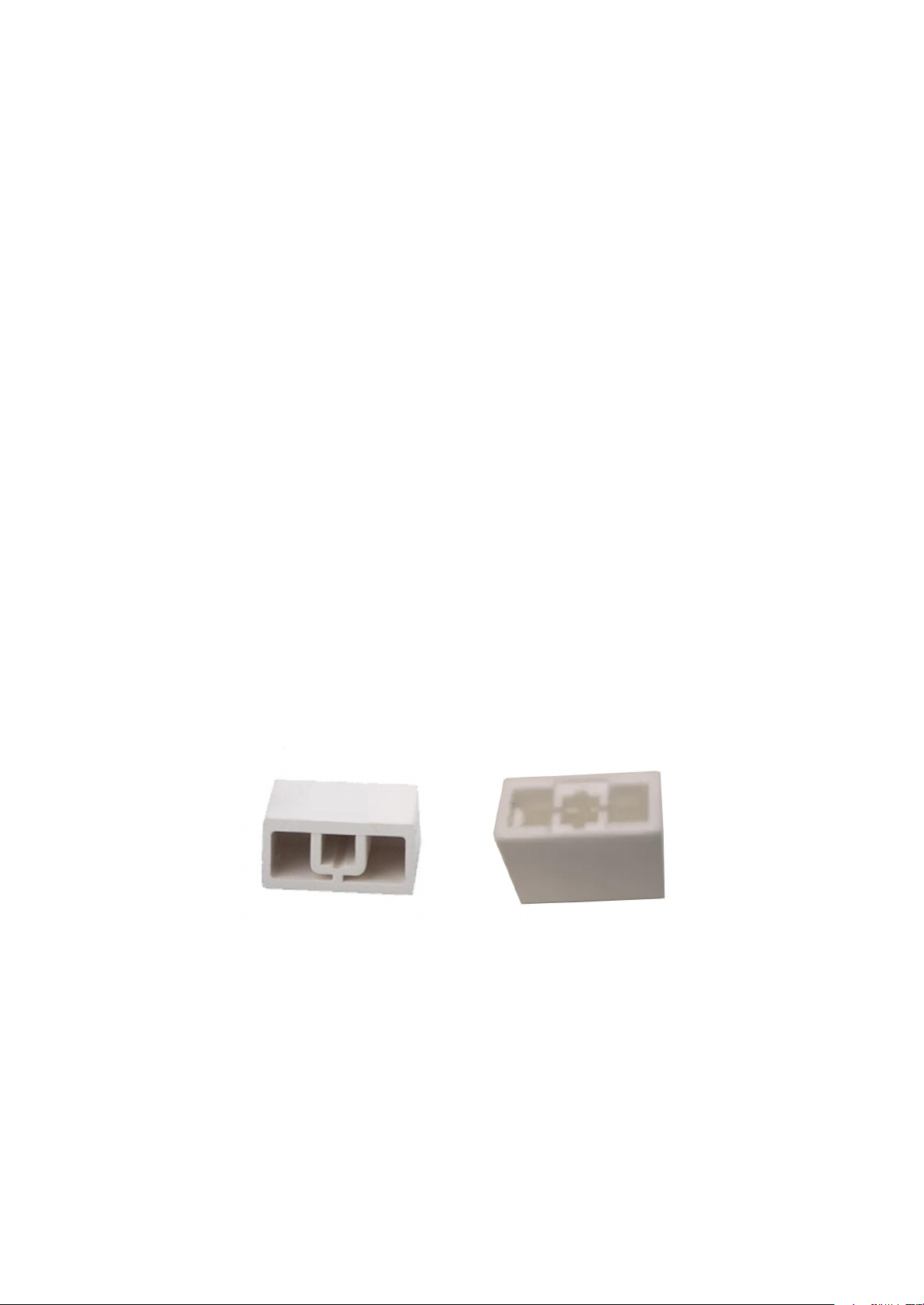
EQL / PHASE SWITCH
The push-button switch for the EQL and PHASE is just a regular dual DPDT switch.
The vintage ones were aligned a little bit differently than the newer ones, so the caps
are technically not interchangeable. The difference is that the olds button caps have
their mounting hole lower. To compensate for that the push button switches are
installed a little lower in the chassis.
Here is a picture of old ISOSTAT caps (left) and modern caps used by AMS Neve
(right).
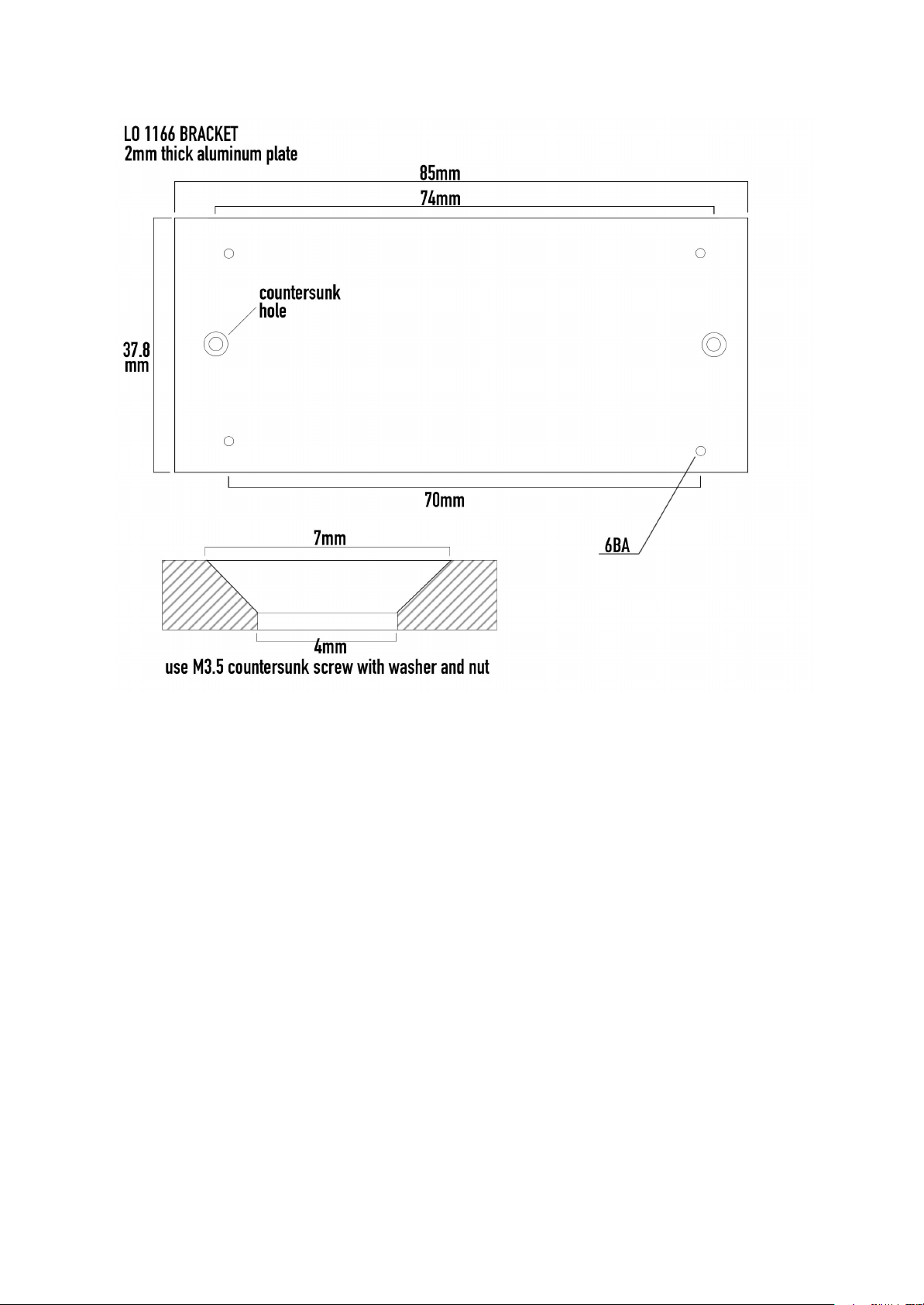
LO 1166 BRACKET
The use of the LO1166 bracket is important if you’re going to put your module into a
rack or a console. The two screws that hold the transformer would be in the direct
path of the plastic rail that holds the chassis in place. It would end up damaging the
rail if you were to force it in.
Here’s the measurements that I have taken from an original vintage bracket.
ATTENTION: The screw holes that are shown here might not align with the chassis that you
are using for your build. The holes that hold the LO1166 in place will always be correct so
don't worry about those.
1073 Building Guide
IMPEDANCE SWITCH HOLE
Version 1.1 7
This one is fairly simple. Some chassis might have a hole that is too small if you’re
planning to use either a vintage or the one that AMS Neve uses today. You can
absolutely use a smaller switch since the switch is just a regular DPDT switch. If the
hole is too small just use a reamer. The chassis is thin enough to use a hand reamer,
just be careful to stay straight and to clean up the hole with a deburring tool.
I have found cases for sale on Ebay and also through GroupDIY. The one I purchased
through Ebay came with the pushbutton switch and the caps but had no bracket for
the LO 1166 and the one I purchased through a seller on GroupDIY had no push
button switch included but had the pushbutton caps and the LO 1166 bracket.
1073 Building Guide
VINTAGE OR MODERN PARTS?
Version 1.1 8
Now there’s two ways to go about building your preamp: vintage parts and new
modern parts. Of course, you can absolutely mix and match because some parts are
just better nowadays (performance wise and footprint wise). Although you could
argue that some parts are better sounding in their older, lesser performing
counterparts (looking at you, old Motorola 2N3055 transistors).
If you are on a budget, I strongly advise not chasing after old NOS and VOS parts for
your build because as time goes they only get pricier and harder to find. Even when
you find the right rare parts they might not be functioning well because of age.
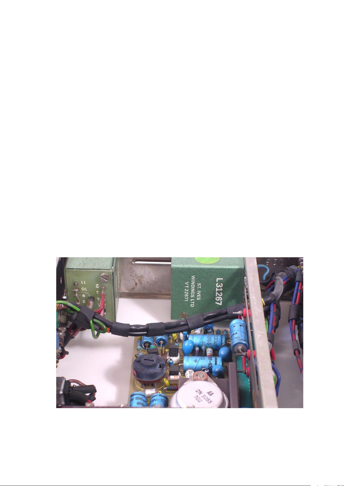
In my opinion the parts that will make the biggest difference in sound in the end are
vintage Marinair / St-Ives transformers (LO1166, 10468, 31267) and vintage Motorola
/ Newmarket 2N3055 transistors. It could be argued that old Mullard mustard / fish
capacitors are influential in getting the vintage sound but since I haven't tested the
difference in sound I will refrain myself from stating an opinion on these. I feel the
rest has little impact on sound compared to these parts.
St. Ives Windings (now Carnhill) were one of the two suppliers of the input transformers. They were
considered interchangeable in the factory. As for the LO1166, Marinair was mainly the sole supplier.

1073 Building Guide
BOM
Part No.
Value
Vintage
AMS
R1
2K2 Ω TR4 2%
R2
56K Ω TR4 2%
R3
68K Ω TR4 2%
R4
1K2 Ω TR4 2%
Version 1.1 9
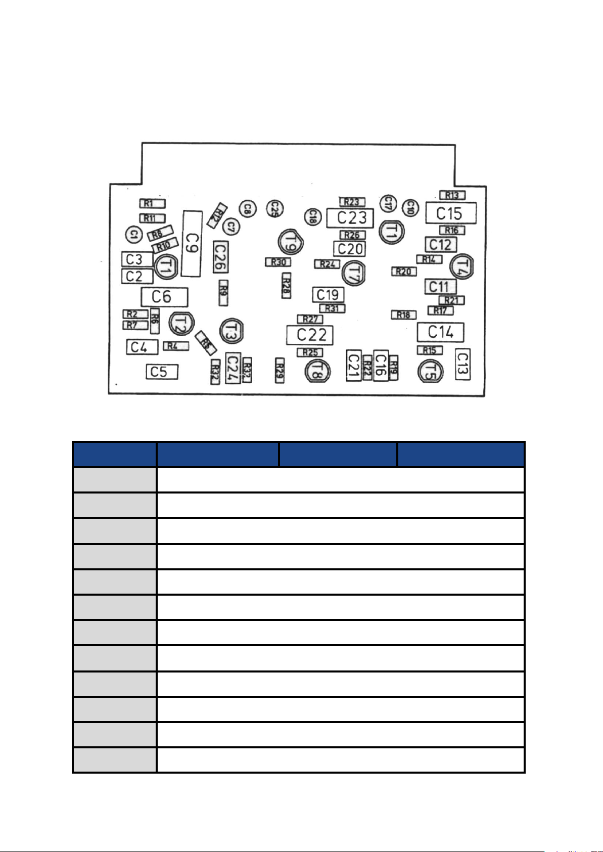
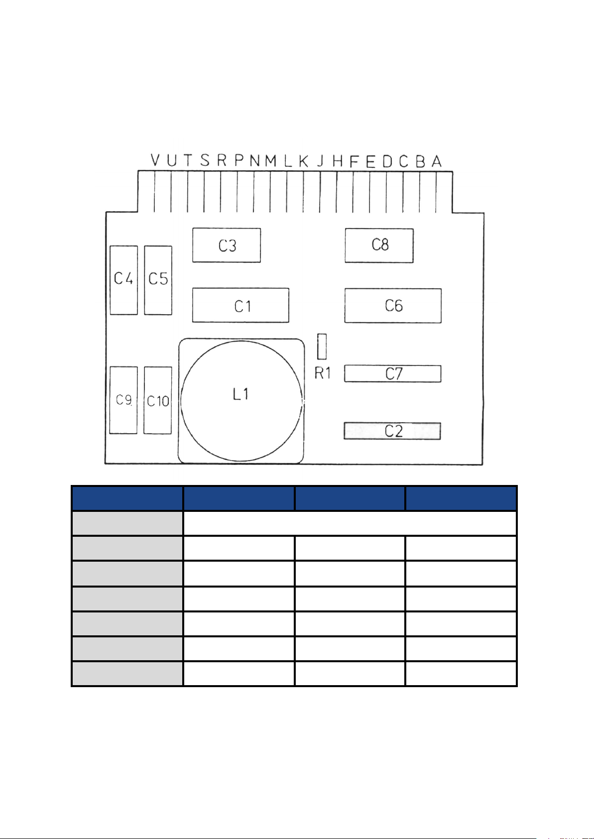
BA283
I made a bill of materials for both the modern AMS module and the vintage modules.
There’s parts where I did not know the brand, hence the empty spots. I did not include
the vintage counterparts for some resistors and tantalums capacitors because
frankly newer ones are just better performing.
NOTE: I recommend getting parts that are over the recommended voltage. For
example instead of buying a 25V capacitor I’ll get a 40V if it fits in the footprint. This
is safer for the module since it lessens the risk of the parts failing.
Map of the BA283 from the “1073 USER MANUAL”.
1073 Building Guide
R5
3K3 Ω TR4 2%
R6
18K Ω TR4 2%
R7
47 Ω TR4 2%
R8
33K Ω TR4 2%
R9
120K Ω TR4 2%
R10
18K Ω TR4 2%
R11
33K Ω TR4 2%
R12
47K Ω TR4 2%
R13
5K1 Ω TR4 2%
R14
470 Ω TR4 2%
R15
1K5 Ω TR4 2%
R16
10K Ω TR4 2%
R17
2K2 Ω TR4 2%
R18
390 Ω TR4 2%
R19
1K8 Ω TR4 2%
R20
51K Ω TR4 2%
RV1
4.7K Ω TRIMMER
C1 Tantalum
10 uF 25V
C2
220 pF
SUFFLEX
C3
4700 pF
SUFFLEX
C4 Electrol.
100 uF 25V
Philips
Vishay MAL2031 25V
C5
330 pF
SUFFLEX
C6, C7
Electrol.
100 uF 25V
Philips
Vishay MAL2031
C8 Tantalum
10 uF 25V
C9
100 pF
SUFFLEX
C10
1500 pF
SUFFLEX
C11
680 pF
SUFFLEX
Version 1.1 10
1073 Building Guide
C12 Electrol.
22uF 25V
Philips
Vishay MAL2031
C13 Electrol.
100uF 4V
Philips
Vishay MAL213833101E3
C14 Tantalum
22uF 16V
C15 Tantalum
22uF 16V
C16
1000 pF
SUFFLEX
C17 Electrol.
400 uF
Philips
330uF(M) 10V Dubilier
TR1, TR2,
TR4, TR5,
TR6
BC184C
NATIONAL
SEMICONDUCTOR
TR3
2N3055
MOTOROLA OR
NEWMARKET
MOSPEC
TR3
HEATSINK
TO-3 Heatsink
CUSTOM MADE
CUSTOM MADE
Version 1.1 11
1073 Building Guide
BA284
Part no.
Value
Vintage
AMS
R1
120K Ω TR4 2%
R2
68K Ω TR4 2%
R3
33K Ω TR4 2%
R4
47K Ω TR4 2%
R5
5K1 Ω TR4 2%
R6
470 Ω TR4 2%
R7
1K5 Ω TR4 2%
R8
10K Ω TR4 2%
R9
2K2 Ω TR4 2%
R10
390 Ω TR4 2%
R11
1K8 Ω TR4 2%
R12
51K Ω TR4 2%
Version 1.1 12
Map of the BA284 from the “1073 USER MANUAL”.
1073 Building Guide
R13, R23
100K Ω TR4 2%
R14, R24
39K Ω TR4 2%
R15, R25
27K Ω TR4 2%
R16, R26
3K3 Ω TR4 2%
R17, R27
120K Ω TR4 2%
R18, R28
180K Ω TR4 2%
R19, R29
180K Ω TR4 2%
R20, R30
3K6 Ω TR4 2%
R21, R31
820 Ω TR4 2%
R22, R32
3K9 Ω TR4 2%
C1, C10, C18
Tantalum
10uF 25V
C2
100 pF 10%
SUFFLEX
C3
1500 pF 10%
SUFFLEX
C4, C13, C21
680 pF 10%
SUFFLEX
C5 Electrol.
22 uF 10%
Philips
Vishay
C6 Electrol
100 uF 25V
Philips
Vishay
C7, C8
Tantalum
22 uF 16V
C9 Electrol.
400 uF 4V
Philips
Vishay
C10 Tantalum
10 uF 25V
C11, C19
47 pF
SUFFLEX
C12, C20
470 pF
SUFFLEX
C13, C21
680 pF
SUFFLEX
C14, C22
Electrol.
22 uF 25V
Philips
Vishay
C15, C23
Electrol.
100 uF 25V
Philips
Vishay
C16, C24
1000 pF
SUFFLEX
Version 1.1 13
1073 Building Guide
C17, C25
Tantalum
22 uF 16V
C26
1000F
SUFFLEX
TR1 TO TR9
BC184C
NATIONAL
SEMICONDUCTOR
TO-92
Mounting pad
TO-92
Were used
sometimes
Is used today
B205
Part no.
Value
Vintage
AMS
R1, R5
6K2 Ω
R2, R4
620 Ω
R3
12K Ω
C1, C2, C3,
C12, C13, C14
100 nF 250V 20%
Mullard Mustard / Fish
C4, C9
22 nF 160V
Mullard Mustard / Fish
C5, C11
47 nF 160V
Mullard Mustard / Fish
Version 1.1 14
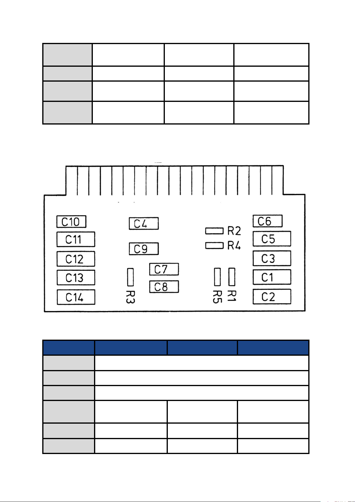
Map of the BA205 from the “1073 USER MANUAL”.
1073 Building Guide
C6, C7, C10
15nF 160V
Mullard Mustard / Fish
C8
10 nF 400v
Mullard Mustard / Fish
B211
Part no.
Value
Vintage
AMS
R1, R4
6K8 Ω
R2
8K2 Ω
R3
2K7 Ω
R5
220K Ω
C1
2.2 nF
Mullard Mustard / Fish
VISHAY MKT
C2 Polystyrene
2.2 nF
SUFFLEX
Version 1.1 15
I know AMS uses Vishay MKT capacitors for most of the capacitors instead of the
Mullard mustard capacitors. Some values are other brands that I am not certain of
the brand so I will leave that section empty. This being said Vishay MKT, SOZO
vintage and TAD are a safe choice.
Map of the BA211 from the “1073 USER MANUAL”.
1073 Building Guide
C3 Polystyrene
4.7 nF
SUFFLEX
C4 Polystyrene
10 nF
SUFFLEX
C5 Polystyrene
220 pF
SUFFLEX
C6 Polystyrene
1.2 nF
SUFFLEX
C7
22 nF
Mullard Mustard / Fish
Vishay MKT
C8
47 nF
Mullard Mustard / Fish
VISHAY MKT
C9
100 nF
Mullard Mustard / Fish
VISHAY MKT
L1
T1280
T1280
T1280
L2
T1530
T1530
T1530
Original inductors are almost impossible to find so your best option is going with
Version 1.1 16
Carnhill’s reproduction of them. They are high quality and have the same
specifications as the vintage ones. Here are the models:
● T1280 = VTB 9044
● T1530 = VTB 9050
1073 Building Guide
BA182
Part no.
Value
Vintage
AMS
R1
10K Ω
C1, C6
1 uF 10% 160V
Mullard Mustard / Fish
ERO MKT 1813
C2, C7
0.47 uF 10%
Mullard Mustard / Fish
VISHAY MKT 368
C3, C8
0.22 uF 10% 160V
Mullard Mustard / Fish
ERO MKT 1813
C4, C9
0.1 uF
Mullard Mustard / Fish
ERO MKT 1813
C5, C10
0.022 uF
Mullard Mustard / Fish
XL3T1295
T1295
T1295
Version 1.1 17
On some older modules as well as the recent AMS reissue there’s no C5 and C10.
Same thing as the last card for the inductor. Here is Carnhill’s model:
● T1295 = VTB 9043
1073 Building Guide
GAIN SWITCH
Part no.
Value
3 wafers 24 eyelets rotary switch
ELMA 04-3133
Switch stop screw
Need 2
SECTION A
RESISTOR POSITION. 9
4K3 Ω
RESISTOR POSITION. 10
3K9 Ω
RESISTOR POSITION. 11
3K3 Ω
RESISTOR POSITION. 12
2K2 Ω
SECTION B
RESISTOR POSITION. 1
2K2 Ω
RESISTOR POSITION. 2
430 Ω
RESISTOR POSITION. 3
270 Ω
RESISTOR POSITION. 4
150 Ω
RESISTOR POSITION. 5
82 Ω
RESISTOR POSITION. 6
47 Ω
RESISTOR POSITION. 7
27 Ω
RESISTOR POSITION. 7-B
33 Ω
RESISTOR POSITION. 8
220 Ω
RESISTOR POSITION. 9
510 Ω
RESISTOR POSITION. 10
1K Ω
RESISTOR POSITION. 11
1K8 Ω
Version 1.1 18
1073 Building Guide
RESISTOR POSITION. 12
3K9 Ω
RESISTOR POSITION.13
12K Ω
RESISTOR POSITION.14
18K Ω
RESISTOR POSITION.16
12K Ω
RESISTOR POSITION. 17 & 18
2K7 Ω
RESISTOR POSITION. 19
3K3 Ω
RESISTOR POSITION. 20
3K9 Ω
SECTION C
RESISTOR POSITION. 14
330 Ω
RESISTOR POSITION 15
120 Ω
You might have noticed the chart here being a little different. To simply put it, AMS
Version 1.1 19
still uses the same ELMA switch they did back in the seventies for the gain switch.
The switch is divided into 3 sections (A, B and C) with 24 positions per section. You
should use the EK20033 drawing (page 33) and the EH10023 drawing (page 22) in
the “1073 USER MANUAL” as a reference but I’ll also include a visual guide in the
wiring section of this guide.
Picture by Baku Pro Audio ©
1073 Building Guide
LOW FREQUENCY SWITCH
Part no.
Value
Vintage
AMS
Resistors
4m7 or 10m Ω
Allen Bradley
Carbon or other
carbon resistor
Regular resistor
4m7 Ω
Rotary Switch +
Potentiometer
2P5W + 50K LINEAR
Jean-Renaud
Rotary Switch +
Plessey
potentiometer /
Sfernice
Blore Edwards
+
Vishay P11S
Part no.
Value
Vintage
AMS
Resistors
4m7 or 10m Ω
Allen Bradley
Carbon or other
carbon resistor
Regular resistor
4m7 Ω
Rotary Switch
2P5W
Jean-Renaud
Rotary Switch
Blore Edwards
C12 Tantalum
22 uF 16v 10%
Part no.
Value
Vintage
AMS
Resistors
4m7 or 10m Ω
Allen Bradley
Carbon or other
carbon resistor
Regular resistor
4m7 Ω
Rotary Switch +
Potentiometer
1P7W + 10K
LINEAR
Jean-Renaud
Rotary Switch +
Plessey
potentiometer /
Sfernice
Blore Edwards
+
Vishay P11S
Version 1.1 20
There’s 2 values for the resistors because both values were used at some point in
the vintage modules. These do not impact sound as they are there to help with “pops”
when using the switch. It is the same with the High Pass Filter Switch and the
Presence Switch.
HIGH PASS FILTER SWITCH
PRESENCE SWITCH
1073 Building Guide
HIGH FREQUENCY SWITCH
Part no.
Value
Vintage
AMS
Potentiometer RV1
10K LINEAR
PLESSEY, SFERNICE
VISHAY P11S
Part no.
Model
Vintage
AMS
T1 MIC I/P
10468
MARINAIR &
ST-YVES
MARINAIR
T2 LINE I/P
31267
MARINAIR &
ST-YVES
MARINAIR
T3 O/P
LO1166
MARINAIR
MARINAIR
Part no.
Value
Vintage
AMS
C1, C3
180 pF
SUFFLEX
C2
470 pF
SUFFLEX
C4, C7. C8, C10
Electrol.
470 uF 25V
PHILIPS
NOVER TE SERIES
C5 Electrol.
100 uF 25V
PHILIPS
Vishay MAL2031
C6
2.2 nF
SUFFLEX
Version 1.1 21
TRANSFORMERS
Just like the inductors, these are hard to find and the vintage ones will cost you an
arm. Again, Carnhill makes a reproduction of those and they are very good. Brands
like BAE use them. Here are the models numbers:
● 10468 = VTB 9045
● 31267 = VTB 9046
● LO1166 = VTB 1148
FLOATING PARTS
1073 Building Guide
C9
0.01 uF
SUFFLEX
C11 Tantalum
22 uF 16V
R8
15K
R10
91 Ω
R31, R32
10K Ω
R37
1K2 Ω
R38
18K Ω
R39
39K Ω
R44, R64
1K5 Ω
R45
12K Ω
R51
270 Ω
R56
12 Ω
R57
120 Ω
R58
2K7 Ω
R70
5K1 Ω
R71, R72
39K Ω
Switch 6 & 7
DUAL DPDT
PUSH-BUTTON
ISOSTAT &
DIALISTAT
TONELUCK
Misc.
Part No.
Value
Vintage
AMS
SHIELDED CABLES
FOIL SCREENED
STRANDED
CONDUCTOR TWIN
CABLE
CANFORD CABLE
CANFORD FST-1
HOOKUP WIRE
MILITARY SPECS
7/0.2 (approx. 24 AWG)
-
-
GROUND WIRE (0V)
AROUND 12 AWG
-
-
Version 1.1 22
1073 Building Guide
SOLDER TERMINAL
(IF NOT INCLUDED IN
CASE)
INSULATED
11152
-
-
IMPEDANCE
SWITCH
DPDT TOGGLE
SWITCH ON-ON
VINTAGE APEM
SWITCH
APEM 106462103
SCREWS FOR EDGE
CONNECTORS
M3 X 12MM
CHEESE HEAD
MACHINE SCREW +
NUT AND WASHER
-
-
EDGE CONNECTOR
X6
18 PIN EDGE
CONNECTOR
AMPHENOL
143-018-01
EDAC
306-018-500-102
SOLDER LUG
M3--
KNOBS
GAIN KNOB
BURGUNDY
MARCONI-SKIRTED
POINTER
I SUGGEST BUYING THESES EITHER FROM
CAPI, DON-AUDIO, DIRECTLY FROM ELMA
OR AML
HPF KNOB
BLUE
MARCONI-SKIRTED
POINTER
-
HIGH FREQ.
DARK GREY
FLUTED-SKIRTED
PRESENCE
-
LOW/MID OUTER
DIAMOND
KNURLED-OUTER
CONCENTRIC
-
LOW/MID INNER
FLUTED
GREY-INNER
CONCENTRIC
-
For the edge connectors you can also use brands like Sullins that have two rows of
Version 1.1 23
pins. As long as you solder your wires and components to the correct side of the pins
your module should work.
1073 Building Guide
ASSEMBLY
Version 1.1 24
Now the fun part! In this section you’ll have all the information to assemble your
module just like a vintage one.
ATTENTION: Depending on the chassis there’s a couple way that Neve used to wire
the modules and the main difference is in the middle section where C4, C5, C7, C8
and C10 are soldered. In this I’ll be covering two of the ways that Neve installed the
middle section. These changes are also gonna influence where a couple of resistors
are installed.
PREPARING THE INPUT AND OUTPUT TRANSFORMERS
Before burying your desk in wires there’s a few things we can prepare like the
connections on the transformers.
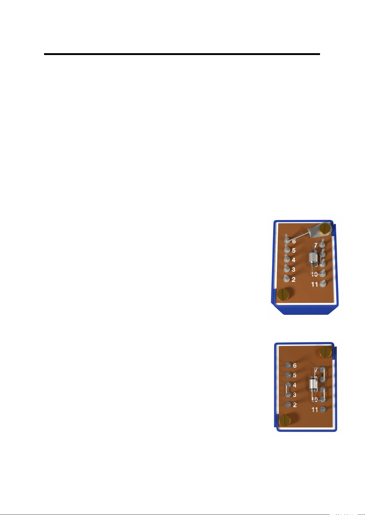
Let’s start with the Microphone Input transformer (10468). You
want to link pins 8 and 9 together. You can use some components
leads or some tinned copper wire and solder at the base of the
pins. After that you can remove the screw closest to pin 6 and
install an M3 soldering lug. Put the screw back in securing the
soldering lug. Use a lead to link the lug to pin 6. Finally you can
solder the C1 capacitor to pins 7 and 10.
If your transformer looks like this, you’re ready for the next one!
The Line Input transformer (31267) is fairly similar. Link pin 4 and
3, 7 and 8 as well as 9 and 10 the same way you did with the other
transformer. Solder the C6 capacitor between pin 7 and 10.
1073 Building Guide
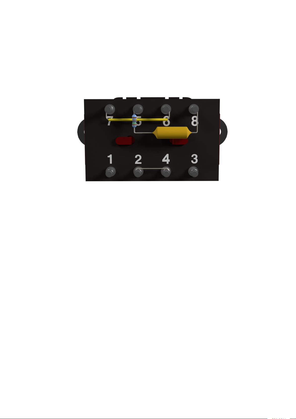
Finally with the output transformer LO1166, solder an insulated wire link between
Version 1.1 25
pins 6 and 7 as well as between 2 and 4. Lots of vintage modules do not have the link
between 2 and 4 insulated but it doesn't hurt to have it insulated.
Now you want to solder the zobel network between pins 5 and 8. This being C9
soldered to pin 8 and the other leg soldered to R64. R64 is then soldered to pin 5.
Your output transformer should now look like this:
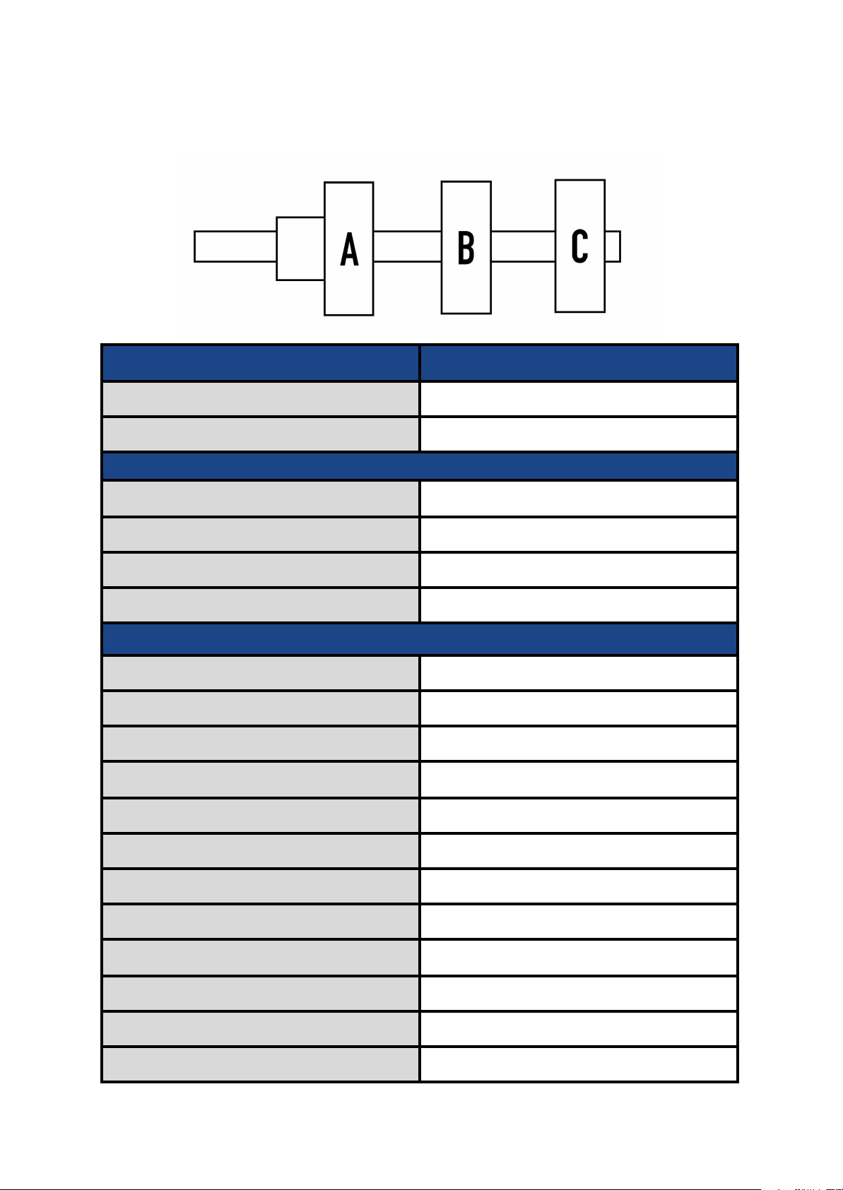
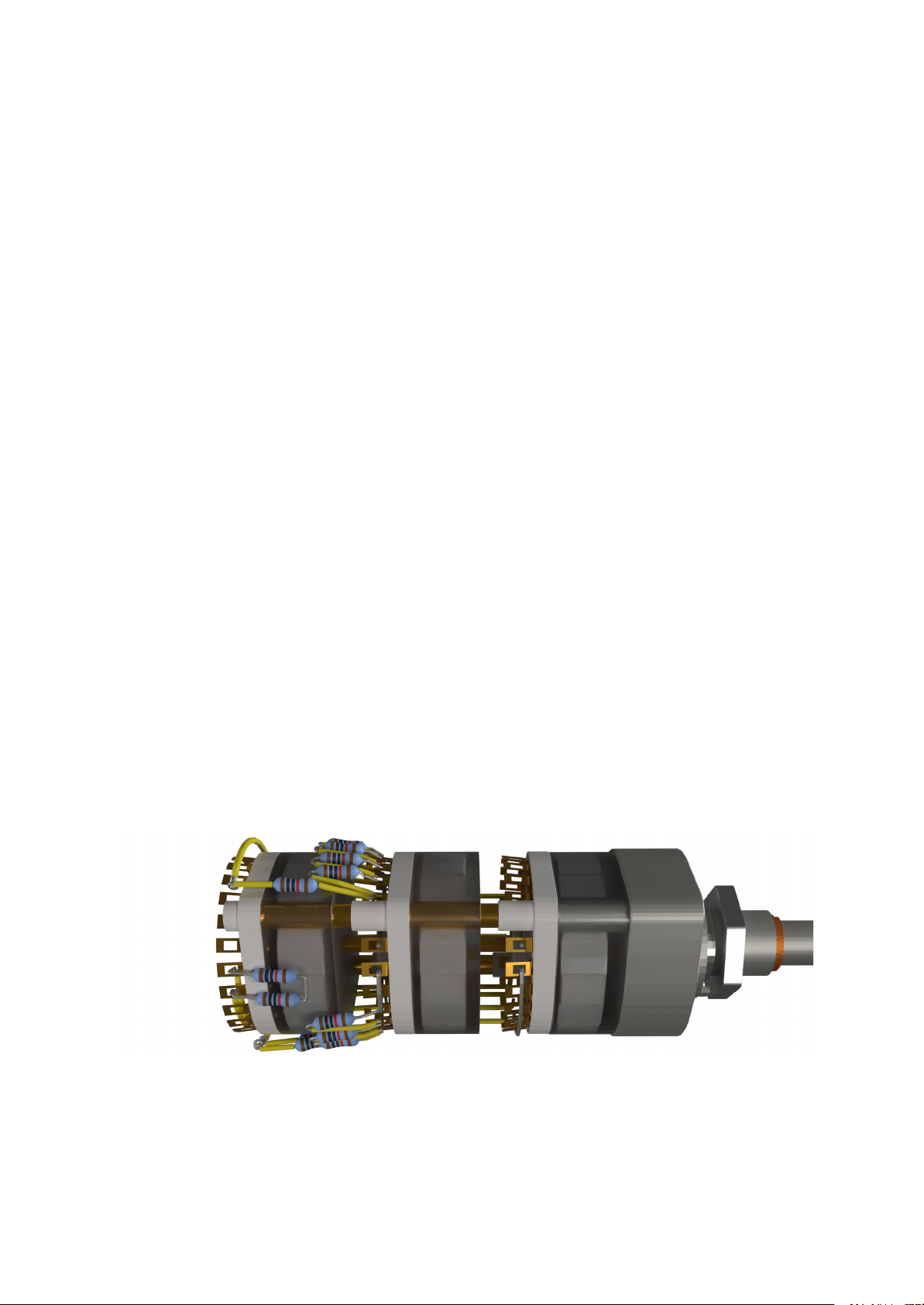
PREPARING THE GAIN SWITCH
The gain switch is a 3 wafers 24 position rotary switch. They’ve been named A, B and
C with A being the closest to the shaft at the front of the switch. For this step I’ll
include some visual references but I strongly advise to also follow the EK 20033
drawing (page 33) in the “1073 USER MANUAL” at the same time.
First I suggest soldering a wire link between the A selector lug to lug 23-A. This will
make it easier to solder your wire after. The solder lug might be a tough spot to reach
with your soldering iron so be careful not to melt your switch. You can disassemble it
to wire the link if you need. Some spots like the 12th and 24th lug can be hard to
reach because they sit behind the switch standoffs. So I suggest soldering your
resistors (if applicable) on those at the same time if you’re to disassemble the
switch. There’s one on 12-A.
1073 Building Guide
I like to install the resistors with shrink wrap on the legs so there’s no shorts or
Version 1.1 26
interference with any other components.
Solder another wire link between the B selector lug to lug 23-B. There’s another hard
to reach resistor on 12-B. Solder all resistors of A section.
You will need some tinned copper wire to solder lugs 16-A to 22-A together. You can
do the same thing for 20-B to 22-B.
Use some more tinned copper wire for the next step. We’ll be making the ground rail
that is installed right before the 3rd wafer (section C) of the switch. You’ll notice that
on the EK 20033 drawing it is portrayed between the A and B section. Make a loop
that goes around the switch and start soldering some resistors from the B section to
the rail. Don’t forget the shrink wraps. You have space to insulate the ground rail
between lug 1 and 7 as well as 12 and 13. Solder all resistors of B section.
For the C section it’s pretty simple. Solder an insulated wire link between lug 14-C and
21-C as well as between 15-C and 22-C. Solder R29 and R30 facing downward and
solder them together on the other end. You can see this connection on picture 1.
Later you’ll be connecting a wire to the end of both these resistors.
Finally place the stop screws in the 23 and 24 position. These go under the A section
close to the switch’s shaft.
Picture 1
NOTE: Resistors on these pictures do not have the correct color codes.
04-3133 with all the resistors soldered to it.
 Loading...