

Neve 1058 User Manual
*- - •
V. -
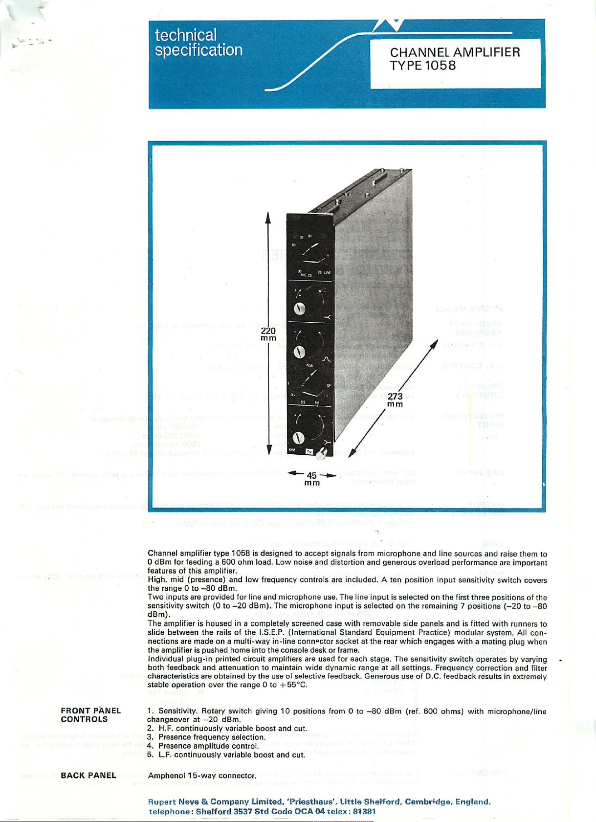
Channel amplifier type 1058 is designed to accept signals from microphone and line sources and raise them to
0 dBm for feeding a 600 ohm load. Low noise and distortion and generous overload performance are important
features of this amplifier.
High, mid (presence) and low frequency controls are included. A ten position input sensitivity switch covers
the range 0 to -80 dBm.
Two inputs are provided for line and microphone use. The line input is selected on the first three positions of the
sensitivity switch (0 to -20 dBm). The microphone input is selected on the remaining 7 positions (-20 to -80
dBm).
The amplifier is housed in a completely screened case with removable side panels and is fitted with runners to
slide between the rails of the I.S.E.P. (International Standard Equipment Practice) modular system. All con
nections are made on a multi-way in-line connector socket at the rear which engages with a mating plug when
the amplifier is pushed home into the console desk or frame.
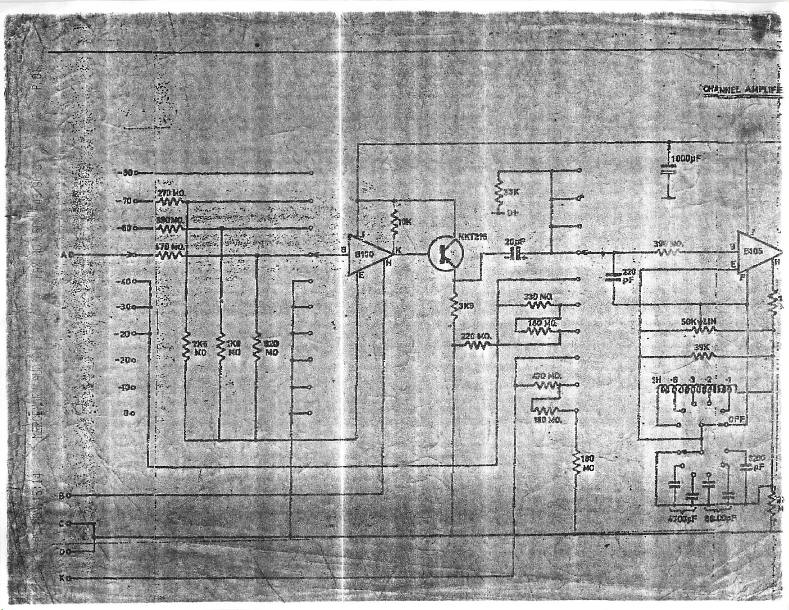
Individual plug-in printed circuit amplifiers are used for each stage. The sensitivity switch operates by varying
both feedback and attenuation to maintain wide dynamic range at all settings. Frequency correction and filter
characteristics are obtained by the use of selective feedback. Generous use of D.C. feedback results in extremely
stable operation over the range 0 to +55°C.
FRONT PANEL 1. Sensitivity. Rotary switch giving 10 positions from 0 to -80 dBm (ref. 600 ohms) with microphone/line
C O N T RO L S c ha n ge o v e r a t - 2 0 d B m .
BACK PANEL
2. H.F. continuously variable boost and cut.
3. Presence frequency selection.
4. Presence amplitude control.
5. L.F. continuously variable boost and cut.
Amphenol 15-way connector.
Rupert Neve & Company Limited, 'Priesthaus', Little Shelford, Cambridge, England,
telephone: Shelford 3537 Std Code OCA 04 telex: 81381
PERFORMANCE
FREQUENCY
RESPONSE
L.F. CONTROL
CHANNEL AMPLIFIER
TYPE 1058
With all controls flat: 20Hz - 20.000 Hz ±0-5 dB with reference to 1.000 Hz.
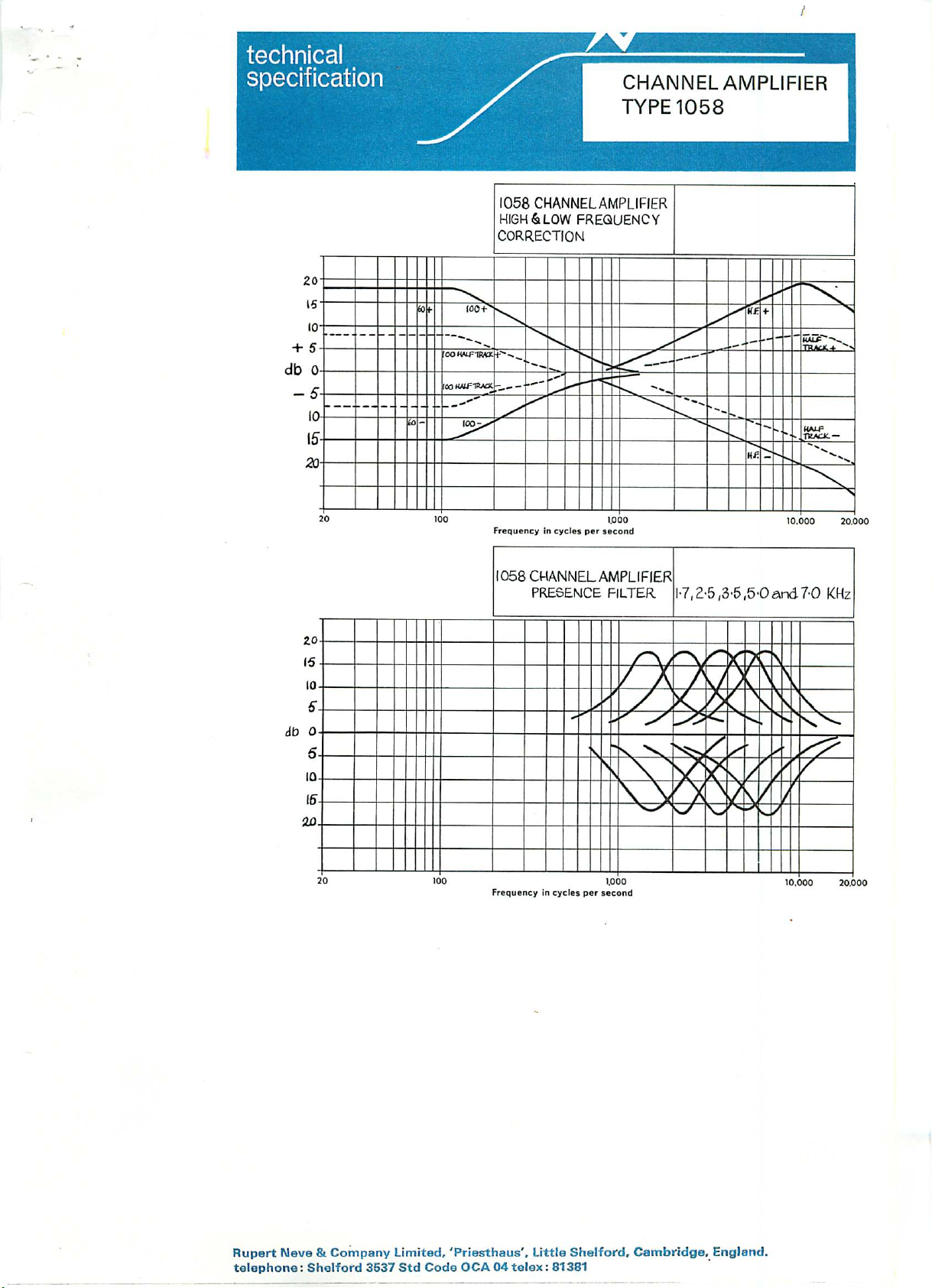
Continuously variable to maximum of ±16 dB at 40 Hz.
H.F. CONTROL
PRES E N C E C o n tinu o u s ly v a riab l e 0 to ± 16 d B.
CONTROLS Switched presence frequencies peaking at 7-0, 50. 3-5. 2-5, and 1 1 KHz.
MICROPHONE
INPUT
LINE INPUT
OUTPUT 1. Source impedance 35 ohms to feed 600 ohm load. Balanced and floating, reactive component less than 20%
I M PEDANCE b e t w e e n 5 0 and 1 0 . 0 0 0 H z .
GAIN + 80 dB ref. 600 ohms at maximum sensitivity.
NOISE Better than -125 dBm equivalent input signal referred to 600 ohms (Equivalent to -128 dBm ref. 300 ohms or
DISTORTION Less than 001 % at 0 dBm into 600 ohms
POWER
REQUIREMENTS
CONNECTIONS
Continuously variable to maximum of ± 16 dB at 10 KHz.
A range of externally mounted plug-in transformers is available giving input impedances of-
7 - 5 / 3 0 o h m s 1 5 0 / 6 0 0 o h m s
5 0 / 2 0 0 o h m s 3 0 0 / 1 2 0 0 o h m s
Balanced and floating. Reactive component less than 20% between 50 and 10.000 Hz.
600 ohms unbalanced selected at -20 dBm point on sensitivity switch. For use with external 10K ohms line
input transformer.
2. Source impedance 0-25 ohms to feed 250 ohms load or higher.
Variable by switching in 10 dB steps to 0 dBm.
-138 dBm ref. 30 ohms).
0-03% at +10 dBm into 600 ohms
0-1% at +20 dBm into 600 ohms
24 volts D.C. ±5% at approximately 100 mA.
A I np ut 0°
B Input 180 ° Mic.
C 24 volts +
D 24 volts +
E -
F -
H J Either +Ve or-Ve H.T. supply should be connected to point L (Module case) at one point only in the system.
When a number of modules are used together, 'L' should be connected to the frame or desk in which they are
mounted and the frame itself connected to one side of the supply at one point only.
7 5 / 3 0 0 o h m s 2 5 0 0 / 1 0 . 0 0 0 o h m s
K Line input
L U nba la nced ou tpu t
M Output 0°
N Output 180°
P 24 volts R 24 volts +
S Chassis
DIMENSIONS
The front panel measures 45 mm.x 220 mm. (1 -75*x 8-70'). Amplifiers should be spaced on 46 mm. centres
horizontally and 222 mm. centres vertically to allow for clearance between units.
technical ^—
specification /
I058 CHANNEL AMPLIFIER
HIGH & LOW FREQUENCY
CORRECTION
/v
CHANNEL AMPLIFIER
TYPE 1058
+ 5-
db 0-
10-
IT-
7a-
«-
~*
-.
^^^^_ *
""SSJf"-s«
KA1-F
-. TK/CK.—
"^^
"\
^N
0.000 20.0
"~~*\^
at- {00i>
OOH'ifTRO;
5-
2 0
[00 KJiftttAX.
f°
00 1C 00
?•«»,.
■•^«.
—-
V—"~
IOOt^
Frequency in cycles per second
!058 CHANNEL AMPLIFIER
PRESENCE FILTER
J^^-——""" ■
.. %.„
».———
*««
■7,2-5,3-5,5-0and 7-0 KHz
'hf.
*"».»
Hi:
Frequency in cycles per second
1.000
Rupert Neve & Company Limited, 'Priesthaus', Little Shelford, Cambridge, England,
telephone: Shelford 3537 Std Code OCA04telex: 81381
10.000 20.000
■ ■■■;:
mk
■ M
'*>'. ■■'-*'• i'-.
1 i I I rrrr
ItaaMik
................ .
;< 'i' .5. ' .; ■•.
f w
■*;%#••
■^j • •: 6
$ j, r.
v>:
,■ <fti '••?
." , 'W
■«!
;.»;
.' S'
r§~%
■"'■:i ■■•■-... . "'•' '
■*wty*ytf<- ■■ .M^IM—U . ■'.
■kr.
' ■:■
■■ ■.. .:
HH
. A*-
:B4
 Loading...