

Page 1
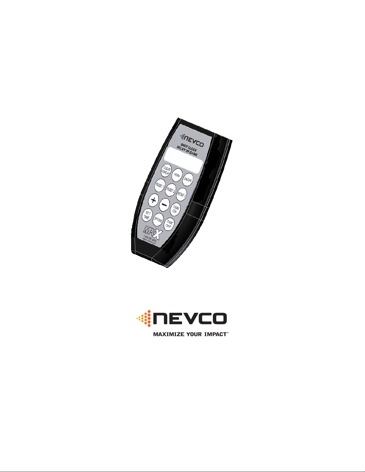
Scoreboard Operator’s Instructions
MPCX SCD / DGT / Pitch Time Control
Since 1934
Retain this manual in your permanent files
Rev. 2/3/2012 135-0136
Page 2

These Instructions are for the Following Models:
LED models:
Incandescent models:
SCD-5
S60-LED
SCD-7
SCD-7A
9520
9620
DGT-5
DGT-5A
DGT-6
SEG-14
SEG-18
S60
SCD-4
Note: Some features may not be available
on some models.
May not be compatible with certain older scoreboards
DGT-2
3020
Thank You
Thank You for choosing NEVCO. We appreciate your business.
The following instructions will help you become familiar with the operation and features of the scoreboard
system.
Please take a few minutes to study this manual, and to practice with the control.
If you ever have any questions or comments, please call or email us.
NEVCO GUARANTEE
To view or receive the most recent copy of the Guarantee, please visit our website, www.nevco.com
or call 1-618-664-0360
NEVCO, Inc.
301 East Harris Avenue
Greenville, IL 62246-2151 USA
USA TOLL-FREE 800-851-4040
CANADA TOLL-FREE 800-461-8550
International Telephone: +1-618-664-0360
Website: www.nevco.com
Email: [email protected]
Page 3

MPCX Receiver
MPCX
CONTROL
(rear
view)
Battery
C
ompartment
T
IME
ON
T
IME
OFF
CLEAR DISPLAY (blanks the SCD,
Add to or Subtract from
the
selected
SET TIME
OPTIONS key
BNC
Connector
(Signal out to scoreboard)
LED Status Indicator
Power Input
Not Used
(On st eady = P ower)
(Blinking = Signal I/O)
(9 V DC)
HORN
PTD, or DGT displays)
3 Programmable RESET keys
feature / also used to select options
(SCD / DGT/ PTD Time and
program the 3 Reset keys)
MPCX SCD / DGT/ PITCH TIME CONTROL
Belt Clip
Cover (2 x AA)
LCD Display (16 characters x 2 lines)
Power ON / OFF Switch
Allows you to:
Set Brightness of Scoreboard
Check Battery Level
Check Signal Strength
Turn Security ON/OFF
Re-link Control
Select Scoreboard Type
Page 4

TABLE OF CONTENTS
QUICK START GUIDE ................................................................................................................. 1
TO S
TART A NEW GAME
TO S
TART THE TIMER
TO S
TOP THE TIMER
KEYBOARD FUNCTIONS............................................................................................................ 2
GREETING
MAIN
SET TIME
OPTIONS M
Standard Options ..................................................................................................................... 5
Advanced Options ....................................................................................................................6
Procedure to mate a control and receiver(s)........................................................................... 7
Setting Scoreboard Model........................................................................................................ 8
TROUBLESHOOTING CHART..................................................................................................9
SCREEN
SCREEN
SCREEN
............................................................................................................................... 3
ENU
................................................................................................................ 1
.................................................................................................................... 1
....................................................................................................................... 1
...................................................................................................................... 2
........................................................................................................................ 4
........................................................................................................................... 5
Page 5
QUICK START GUIDE
MPCX
SCD
/
DGT
R1: 15
Time:OFF
ON
OFF
R1: 15 Time:OFF
R1: 15 Time:OFF
R1: 15 Time:ON
SHOT CLOCK, SEGMENT TIMER, DELAY OF GAME, and PITCH TIME models
Shot Clock (models SCD-5, SCD-7, and S60-LED).
Delay of Game (model DGT-5).
Pitch Time (model 900-9520)
Segment Timer (model SEG-14 and SEG-18)
Note: It is assumed here that the control has been configured for the correct scoreboard type and the control has been linked to the
desired receiver(s). Both functions are explained in the setup guide that comes with a new control. The control is set to “SCD” models
by default at the factory. Switch it to Delay of Game, Segment Timer, or Pitch Timer series if needed in the field from the OPTION
menu. It is assumed that the receiver is powered ON.
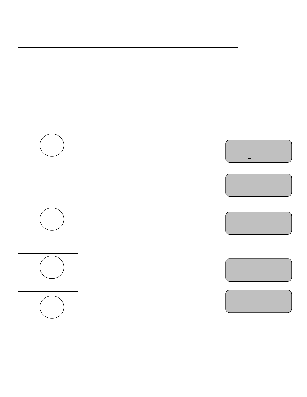
To Start a New Game
Press
The control will display a greeting while it establishes
communications with its receiver(s). (Up to 30 seconds).
Press To set the timer to the value the key is set to.
You are now ready for the game to begin.
ON/OFF
Next the display will show the preset time for RESET 1
key, the time status, and the current preset times for
RESET 2 and RESET 3 keys.
Note: The cursor indicates the active function.
RESET 1
»»»
R2: 30 R3: 35
R2: 30 R3: 35
To Start the Timer
Press
To Stop the Timer
Press
Please consult the following sections of this manual for more details, functions, and features
TIME
TIME
The control will display
The control will display
R2: 30 R3: 35
R2: 30 R3: 35
1
Page 6

KEYBOARD FUNCTIONS
MPCX
SCD
/
DG
T
Accessed
GREETING screen
»»»
ON/OFF
When you are done using the control turn it OFF to conserve
batteries.
Note: Always power ON the receiver(s) (scoreboard(s)) first, and wait a few seconds for the receiver(s) to initialize
(red LED illuminates) before powering ON the control. If the control is already ON, turn it OFF, wait a few seconds,
and then turn it back ON.
Note: If the scoreboard fails to respond to the control, power the control OFF, wait a few seconds, and then try
again. Please allow time for each control to complete its powering ON process (main screen appears) before turning
ON another control.
GREETING
When the control is Powered ON, the greeting showing the
type of control and the sport is displayed. This greeting
continues to be displayed while the control establishes
communications with its receiver(s). (May take up to 30
seconds)
by
pressing
ON/OFF
2
Page 7

MAIN screen
R1:
15 Time:OFF
Accessed
R1: 15 Time:OFF
OFF
OFF
ON
R1: 15 Time:ON
R1: 15 Time:OFF
Rst1:15 Time:OFF
R2: 30 R3: 35
Press RESET 1, 2, or 3 at any time to immediately reset the
timer to its preset value.
Note: Time set to ON: If the current counting time has not expired and another time is selected using RESET (1-3),
the new time value will be loaded and will begin counting immediately with no further action needed.
Note: If the current loaded time has expired or the timer is stopped and RESET (1-3) is pressed, the new time value
will be loaded immediately, however it will not begin counting until the TIME ON key is pressed.
TIME
Turns the time ON.
TIME
Turns the time OFF.
HORN
Sounds the horn. (Approximately 2 seconds)
Note: Does not change the control display.
Note: Hold key down to extend duration.
CLEAR
DISPLAY
Clears (Blanks) the timer displays.
Note: If, when the main screen appears, the timer displays remain dark and will not
respond to the control, then the receivers were not found. Power the control OFF, make
sure all associated receivers are powered ON, and try the control again. Please allow time
for each control to complete its powering ON process (main screen appears) before
turning ON another control.
MAIN
The main screen shows the reset time for the Reset 1 key, the
Timer Status, and the reset time for the Reset 2 and Reset 3
keys. Press any one of these Reset keys to immediately load its
value into the timer. The reset values for these three keys can be
changed by using the SET TIME screen.
Note: The control stores three times for SCD mode and three times for DGT mode.
A CLEAR DISPLAY key is available for blanking the timers
during the last few seconds of main time when they are no
longer needed.
You should keep this screen displayed during the game.
RESET 1
RESET 2
R2: 30 R3: 35
R2: 30 R3: 35
R2: 30 R3: 35
Rst2:30 Rst3:35
3
TIME
RESET 3
by
pressing
Page 8

Set Time:
TIME
TIME
Time Is Running
Set Time:
Set Time:
Set Time:
TIME
TIME
Accessed
screen.
Set Time:
TIME
Time: 120
Note: The SET TIME is active only if the time is stopped.
Pressing it with time running causes the control to prompt.
The first press of the SET TIME key brings up a screen for
SET
setting the displayed time. Use the “+” or “-” keys to select
the time (0-199).
Note: Only the Pitch Timer is able to go up to 199. For Shot clock and Delay of Game Timer the timer
will only go up to 69. It is capable of counting down from 199 but the display will not display proper time
until 69 seconds are left.
Note: Hold the key down for fast advance.
SET TIME screen
SET TIME
This screen is for setting a special miscellaneous time into the
timer. It also provides a way to program the desired times into
each of the three RESET keys. These keys can then be pressed at
any time to instantly load the timer with each keys reset value.
Note: Press the TIME OFF key at any time to return to the main
Stop Time To Set
SCD/DGT Time: 0
by
pressing
SET
Note: You can press one of the Reset keys first then adjust the displayed time up or down as needed with
the “+” and “-” keys.
Press again to set the RESET 1 time:
SET
Use the “+” and “-” keys to enter the desired
preset time.
Note: Hold the key down for fast advance.
Reset 1 Time:15
Press again to set the RESET 2 time:
Use the “+” and “-” keys to enter the
desired preset time.
SET
Reset 2 Time: 30
Note: Hold the key down for fast advance.
.
Press again to set the RESET 3 time:
SET
Use the “+” and “-” keys to enter the
desired preset time.
Reset 3 Time:35
Note: Hold the key down for fast advance.
Note: Any of the three programmable Reset keys can be set to any umber of seconds from 0 to 199.
Note: Separate times are stored for Shot Clock, Segment Timer, Pitch Timer, and Delay Of Game modes. Refer to
options Menu
Note: To return to the main screen, press the TIME OFF key.
Note: Some timers will display tenths of seconds while others display only whole seconds. In all cases the time is
divided into fractions of a second for greater accuracy. It may be possible to start and stop the time and see no
change in the displayed time even though several fractions of a second may have been counted off. The fractions of
seconds are always cleared when a new time is set.
4
Page 9

OPTIONS Menu
Battery Level
Signal
Strength
Signal
Strength
Sign
al Strength
Set Brightness
Time Direction
Auto Horn
Several option settings are available to fine tune the scoreboard system to your needs. These
settings are saved in the control. They are remembered even if the control is turned OFF or the
batteries removed. When a control turns ON the scoreboard, these settings are sent to the
scoreboard and are used to define how it operates. This allows each coach or group to have their
own control with its unique option choices, thus eliminating the need to set up the options every
time the scoreboard is used. For example, Brightness (Baseball – day time) (Soccer – night time).
It is also possible to use more than one control to operate the scoreboard. For instance, the Time
can be controlled by one person while someone else operates the rest of the scoreboard with
another control.
Standard Options
OPTIONS
Allows you to select the Brightness Level of the
scoreboard. (Bright or Dim)
Reports the condition of the batteries in the control.
The options key can be used to access the following features. Each press of the options
key moves you to the next option screen. When all options screens have been accessed
you are returned to the main screen.
Note: In this illustration the cursor indicates the default factory settings.
(+)Bright (-)Dim
Allows you to change the direction time counts
(+)Up (-)Down
Some scoreboards (timers) that this MPCX is compatible
(+)On (-)Off
with have a horn. It can be used to sound at the end of
time. This enables or disables that function
L >>>>>> H
Allows you to check signal strength when connected to a
receiver.
Press(+)
Used as an indication of reliability of communications.
Affected by distance, battery condition, obstructions and signal
interference.
L >>>>>>>>> H
5
Page 10

Advanced Options
Enter Code to
Security
This menu option allows you to access settings that affect how
the control operates. Generally, these settings need not be
Change Settings
changed and should only be changed by an experienced operator
or under direction from the Nevco Service Department.
Press the following key sequence:
RESET 1
to gain access to the following additional menu items.
Press the OPTIONS key to return to the main screen.
The Security setting is used to allow multiple controls to
simultaneously operate the scoreboard.
(+)On (-)Off
With the Security set to (+)ON, the scoreboard will ignore all
other controls and can be operated only by the control that turned
it ON. When this control is turned OFF another control can be
used to turn the scoreboard ON. Should the batteries go dead or
the 1st control leave the area – Power must be cycled to the
scoreboard to allow another control to operate the scoreboard.
If the Security is set to (-)OFF, multiple controls can be used to
operate the same scoreboard or scoreboard system. This allows
one person to operate part of the scoreboard, such as the clock,
while someone else operates the rest of the scoreboard with
another control. Allow each control to establish communications
with its receiver(s) (Greeting screen disappears) before powering
ON the next control.
Note: Set the Security of ALL controls used in a multi-control system to
(-)OFF.
Note: All controls need to be configured for the appropriate scoreboard model
group and linked to the same receiver(s).
Note: The control display will only update when keys are pressed.
Note: Make sure all controls of a multi-control scoreboard system are
powered OFF before starting the system. Power ON the system receivers,
then, power ON the control that will determine the scoreboard attributes
(Brightness Level etc.). Next; power ON the remaining controls. Please allow
time for each control to complete its powering ON process (main screen
appears) before turning ON another control.
+
-
Or
RESET 2
6
Page 11

This menu option reports the number of receivers the control is
L
ink Control
0/0
Change Settings
+
-
currently linked to (0/0), and the number of receivers on its “Link
Press (+)
To” list (0/0). The option also allows you to link a control to a
scoreboard (receiver) or group of scoreboards (receivers). This
link procedure is required only at the time of installation, when
additional controls are added to an existing system, a change to
the system configuration is needed, or a control or receiver has
been repaired or replaced.
An MPCX control can operate up to eight scoreboards (receivers)
in a dual type configuration. (All scoreboards must be in the same
model series).
Procedure to mate a control and receiver(s)
Step 1. Insert the batteries included with the MPCX control or turn the control ON by pressing
Step 2. Power up one to eight receivers using the 9V wall plug-in power supply provided with
the receiver. Because all receivers powered up and within range of this control will be
linked to this control with this procedure, power down all receivers not to be mated with
new control.
Step 3. Press the button until the display reads
Options
Enter Code to
ON/
OFF
Step 4. Enter the “Code” with the buttons in the sequence
Guests
Step 5. Continue pressing the button until the display reads
Options
Link Control 0/0
Press (+)
Step 6. Press the button. The control will link to all receivers in range.
Step 7. This process could take as long as 3 minutes. The control will automatically reset when
linking is complete and each scoreboard connected to a “linked” receiver will light.
Repeat steps 3 – 5 in the “Re-Mating” procedure below to ensure the correct number of
receivers are linked indicated by 0/0 on the “Link Control screen”. The 0/0 on this screen
indicates how many receivers are found / how many receivers are linked.
If more receivers than intended are linked to the control, then power down any MPCX
receivers in the area that are within 2000’ and repeat the process. If you cannot find these
receivers, or they are located on an adjacent property, you may have to perform this
process in another location.
This process creates a list of receivers in the control. The control can only communicate
with receivers on this list. The list remains intact even if the batteries are removed from
the control. During normal operation (with any or all receivers ON), when you turn the
control on, it searches for receivers on its list and the scoreboard(s) will light.
Note: During normal operation, the receiver should always be powered ON before the control. In a multi-control
system, the controls must be powered ON and allowed to find the receiver one at a time. Wait about 30 seconds
between powering-up controls.
7
Page 12

Setting Scoreboard Model
Scoreboard Model
Scoreboard Model
Scoreboard Model
Scoreboard Model
The next press of the options key will display one of the following screens. It
OPTIONS
indicates which of the scoreboard model series the control is currently configured
to operate. Use the “+” key to toggle thru the scoreboard models. Press the
OPTIONS key again to exit the options routine. The last scoreboard series
displayed will become the new control configuration.
For models SCD-5, SCD-4, SCD-7, S60, and S60-LED
Shot Clock (+)
For model DGT-5, DGT-5A, DGT-6, DGT,2, and 3020
Delay Of Game (+)
For models SEG-14 and SEG-18
Segment Timer(+)
Pitch Timer (+)
For model 9520, 9620
8
Page 13
TROUBLESHOOTING CHART
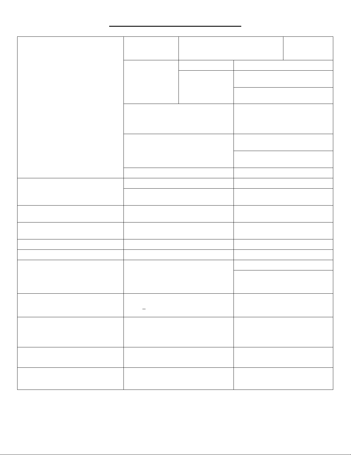
Problem Cause Solution
Scoreboard/Segment Timer will not turn
ON when control is turned ON
Control continues to search after an
unusually long time
Data won’t change on control
Control display shows incorrect
information
Cannot turn the time ON
Receiver not
working
Control signal weak
Check signal
strength (see
Options menu)
Control is linked to extra unwanted receivers
or wanted receivers are not powered ON.
Control is not linked to this scoreboard
Didn’t sync up Power control OFF, then ON
Check LED status indicator on receiver
(on solid = power, blinking when key is
pressed on control = has signal I/O)
Battery level low Replace batteries
Make sure the control is in clear line of
Control in a poor
location
sight of the scoreboard
Move closer to scoreboard
Use the Options Menu to check the
number of receivers the control is linked
to and the number of receivers on its
list.
Find and use the control for this
scoreboard.
Link the control to this scoreboard or
group (see Options Menu)
Restore power to
receiver
Control is ON but scoreboard/timer is OFF
(data is changing on control)
Scoreboard/timer is ON but does not
respond to control
My control will not operate scoreboard (1st
control has left area, scoreboard is ON)
I cannot set the time The time is running Stop the time first
Cannot turn the time ON Time at 0.0 and set to count down Set some time on the clock
Scoreboard is ON – Control is OFF
Only one control of a multi-control
scoreboard system will operate the
scoreboard
Scoreboard is being controlled by more
than one control
No power to scoreboard Check all switches, breakers, and fuses
Bad connection between Receiver and
scoreboard module
Control and receiver are not communicating
Scoreboard was left with security ON Cycle power to receiver
Batteries were removed while scoreboard
ON
Batteries were completely discharged while
scoreboard is on
One or more of the controls has its Security
set to (+)ON
Security is set to “(-) OFF”.
Note: The scoreboard assumes the security
of the control that turns it ON.
Check all cables and connections
Turn control OFF, then ON to establish
communications
Install batteries -- power ON then OFF
Cycle power at scoreboard
Set the Security of ALL controls used in
a multi-control system to (+)OFF (See
the Options Menu)
(a) In the Options Menu, set the
Security to “(+) ON”. (b) Turn the
receiver and control OFF. (c) Turn the
receiver ON. (d) Turn the control ON.
Cannot turn OFF all receivers within
operating range. (Linking procedure)
Scoreboard connected to MPCX is
displaying data in the wrong places,
incorrect data, or horn constantly sounds.
If the problem persists please contact the Nevco Service Department.
Another nearby organization also has an
MPCX control system.
Control is not configured for correct
scoreboard model series
800-851-4040
9
Move the receivers to an isolated area
for Linking.
Reconfigure the control (see options
menu)
Page 14

WARNING: To satisfy FCC RF
exposure requirements for mobile transmitting devices, a separation distance of 20 cm or
Features
CE
Specifications
MPCX Control:
o Small and light weight (fits in or clips to pocket)
o Tactile confirmation of key pressed
o High visibility transflective display
o Convenient wireless operation
o Built in wireless signal strength meter
o Power conservation circuitry
o Built in battery meter
o Long battery life
o Uses inexpensive, readily available AA batteries
o Sealed keyboard
o No slip grip
o Ergonomic single hand operation
o Internal antenna
o Mate multiple controls to same scoreboard
o Operate dual scoreboards
o Retrofits to existing wired installations
Size:
Approximately 3¼” x 5½” x 7/8”
Weight:
5½ oz. (including batteries)
Key pad:
12 keys
Display:
32 character LCD
Power requirements:
Two AA cells (included)
Operating distance:
1000 feet (Clear line of sight)
Receiver Output:
One BNC connector (2 loads with up to 1000
ft. coax each)
Operating temperature:
0°F to 150°F
Certifications:
FCC part 15 Class B
RoHS
N
OTE
: This equipment has been tested and found to comply with the limits for a Class B digital device, pursuant to part 15 of the FCC Rules. These limits
are designed to provide reasonable protection against harmful interference in a residential installation. This equipment generates, uses and can radiate
radio frequency energy and, if not installed and used in acc ordance with the instructions, may cause harmful interference to radio communications.
However, there is no guarantee that interference will not occ ur in a particular installation. If this equipment does cause harmful interference to radio or
television rec eption, which can be determined by turning the equipment off and on, the user is encouraged to try to correct the interference by one or
more of the following measures:
—Reorient or relocate the receiving antenna.
—Increase the separation between the equipment and receiver.
—Connect the equipment into an outlet on a circuit different from that to which the receiver is connected.
—Consult the dealer or an experienced radio/ TV technician for help.
The user is cautioned that c hanges and modifications made to the equipment without the approval of Nevco could void the user’s authority to operate this
equipment.
This class B digital apparatus meets all requirements of the Canadian Interference- Causing Equipment Regulations.
Cet appareil numerique de la classe B repecte toutes les exigences du Reglement sure le materiel brouller du Canada.
more should be maintained between the antenna of this device and persons during device operation. To ensure
compliance, operations at closer than this distance is not recommended. The antenna used for this transmitter must not be
co-located in conjunction with any other antenna or transmitter.
10
 Loading...