

Page 1

Patch Panels
151
Page 2

innovative solutions superior quality
Content Page
NPPA-Series - 96 Bantam (TT) Jacks .......................... 154
Configuration, Grounding, Wiring ............................ 155
NPP-TB-Series - 48 B-Gauge Jacks ............................. 156
Configuration, Grounding, Wiring ............................ 157
1/4" Patch Panel NYS Series .................................... 158
Configuration, Grounding ........................................ 159
MA 96 and XPM 96 Bantam Patchbays ..................... 160
MAJ 501 Bantam Jack Socket ................................... 161
LF 48 B-Gauge Patchbays ......................................... 162
LFJ 501 B-Gauge Jack Socket ................................... 163
Technical Data ........................................................ 164
Operating Accessories, Labeling software ................... 164
Ordering Information ............................................... 165
Introduction
Patch Panels are central switching gears between
audio equipments. They are used to switch and
route analog and digital audio signals from and to
equipments in recording or broadcast studios, OB
vans, churches, theatres, stadiums, arenas, etc.
Neutrik
types, wiring and grounding possibilities.
Common versions accommodating Bantam TT, 1/4“
A-gauge and longframe B-gauge jacks on the front
rows are available.
The mechanical size is designed to fit into 1U 19“
standard racks. All Neutrik patch panels offer various
normalling possibilities between top and bottom
row.
All Neutrik
audio signals acc. AES3, 48kHz sampling rate.
®
Patch Panels are available in a varety of jack
®
Patch Panels are able to handle digital
152
NEUTRIK®, opticalCON®, neutriCON®, miniCON®,
nanoCON®, powerCON®, Profi®, speakON®, silentPLUG®,
crystalCON®, etherCON®, rearTWIST®, XIRIUM®, DIWA®
are registered trademarks of Neutrik AG.
innovative solutions I superior quality
Page 3
Audio Normalling
Audio Normalling is usually used with audio patch panels
and is a wiring pattern in which a circuit path is established
from one piece of audio equipment to another without
the use of a patch cord. This pattern is then considered to
be the „normal“ circuit path that is desired most of the
time. If a patch cord is inserted, the normal circuit path is
interrupted and rerouted to a different circuit path.
Normalled patch panels are most commonly found in
vertical jack pairs: the top jack is designated as the source
and the bottom jack is the destination.
Normalling example: HALF NORMALLED BOTTOM ROW
This is the most common configuration, very often
called HALF NORMALLED. In
this configuration internal
normalling contacts connect
the top jack contact with the
corresponding bottom jack
contact. Inserting a plug in the
bottom jack will interrupt this
internal normalling connection,
while inserting a patch cord
into the top jack doesn‘t interrupt the circuit. (Can be used
to monitor the normalling circuit)
Other versions of normalling are Half Normalled Top Row,
Full Normalled, Parallel and Isolated.
www.neutrik.com
153
Page 4

HalfNormalledTop
RN
TN
T
R
S
R
T
S
HalfNormalled Bottom
S
R
T
R
T
RN
TN
S
R
T
S
RN
TN
RN
S
TN
R
T
S
FullNormalled
S
T
RSR
T
Parallel
R
T
T
R
S
R
T
S S
T
R
Isolated
S
RTR
T
S
Key
NPPA-TT-PT
IndividualGrounds toCommonGround
ChassisGround
BottomRow
CommonSignal Ground
ModuleArrangement
TopView
UpperRow
CommonSignal Ground
Grounding
toconnect
SolderingPads
1 2 3 4 5 6 7 8 9 10 11 12 13 14 15 16 17 18 19 20 25 26 4827 28
NPPA Series NPPA Series
Robust front design Easy assembly Jack-pair IDC terminals Push terminals ELCO connectors
NPPA-Series -
96 Bantam (TT) Jacks
NPPA-TT-PT
•
Innovative and compact patching system (just 1U high) for 19“ rack mounting
•
Robustly housed in a black coated steel shell
•
Features 2 x 48 long life gold plated TT size (bantam) Neutrik NJ3TTA double contact point TRS jacks
•
Available in all common normalling configurations (default Half Normalled Bottom)
•
Qualified for analog and digital signals according to AES3, 48 kHz sampling frequency
•
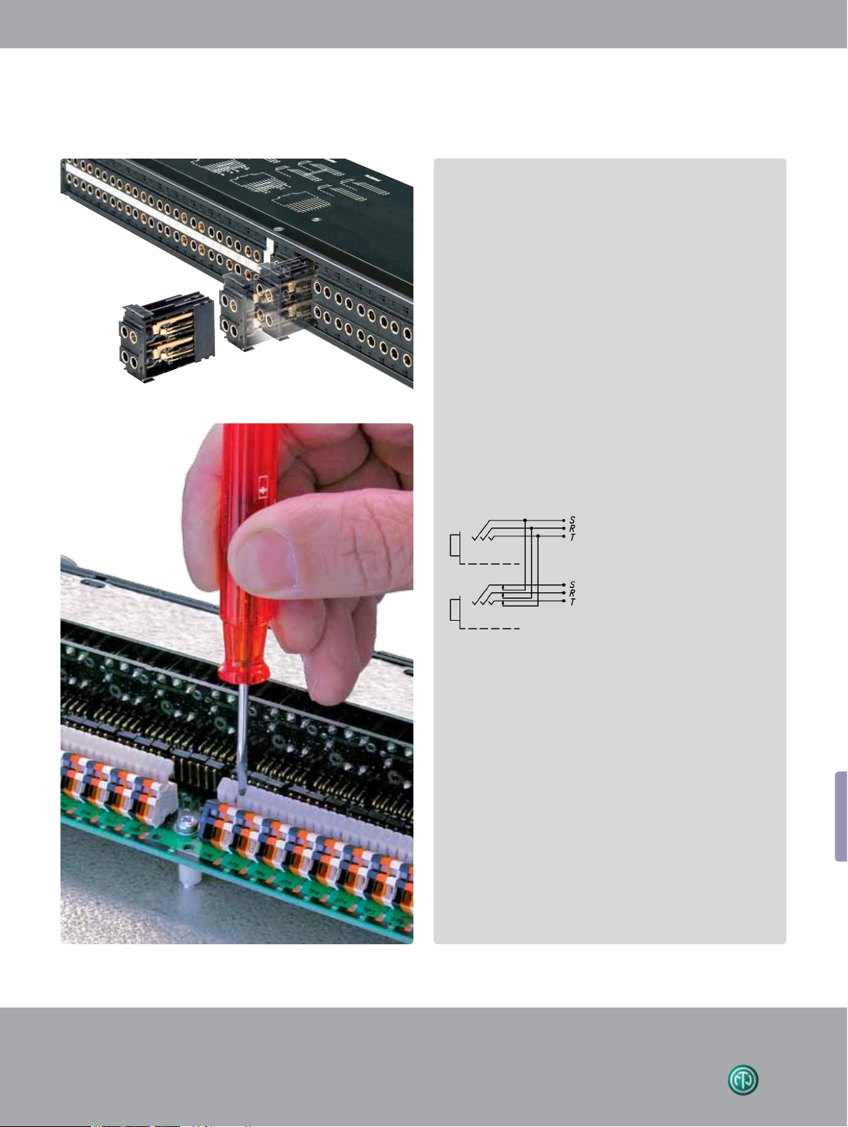
Remove the front panel for quick changes of the NJ3TTA-** modules for reconfiguration or repair even when "on air"
•
Includes two built in cable bars and two wide channel ID strips
•
PatchLink Software for printing onto labeling strips is on Neutrik website (available for PC only)
154
innovative solutions I superior quality
Dimensional Drawing
Page 5
S
S
R
R
T
T
R
T
S
R
T
S
S
T
R
S
R
T
R
T
S
S
T
R
S
R
T
R
T
S
Design Criteria
All NPPA patch panels are fitted with high quality, long life
NJ3TTA gold plated double contact jacks (2x48), featuring best
contact integrity. The unit, robustly housed in a black coated
steel shell, is finished off with a built in cable bar and two large
channel identification strips for perfect management of the
system. The NPPA patch panels are an innovative and compact
patching system (just 1U high) for 19" rack mounting.
Configuration
The standard version of the NPPA Panel is delivered bottom row
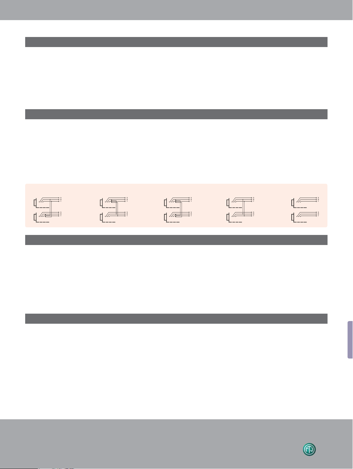
half normalled for each jack pair by default. Further patch versions are available with fully loaded jack-pairs as:
For individual normalling single pre-configured jack-pairs
are offered.
NPPA-TT-IDC is equipped with jumper blocks for individual
switching configurations of each jack channel.
• Full Normalled
• Half Normalled
• Isolated
• Parallel
Note: Take care when handling digital signals. Do not use
parallel configuration and avoid other parallel paths when
using half normalled configurations. Parallel paths may lead
to mismatching.
Half Normalled Bottom Half Normalled Top Full Normalled Parallel Isolated
Grounding
The flexible grounding system provides the following versions:
• Individual: Each channel is individually grounded by its corresponding cable shield (default configuration).
• Group: Selected channel grounds are connected via the ground bus on the PCB using solder bridges and track cuts to form a
group that is connected to one common cable shield.
• Central: All channel grounds (individual top and bottom row) are connected via the ground bus on the PCB using solder
bridges and wired with only one cable shield.
• Chassis-Common: The same as central grounding but with the addition of the common ground bus (top and / or bottom
rows) connected to the patch panel chassis by means of jumpers
Wiring Terminations
TT patch panels offer different choices of wiring:
• Spring loaded push terminals
• 56 pin Elco/Edac male connectors
• 90 pin Elco/Edac connectors
• 50 pin D-SUB connectors
• 25 pin D-SUB connectors
• IDC-Krone terminals
• Solder lugs
For Pin assignment of ELCO / EDAC and D-SUB connectors please see drawings on www.neutrik.com
The spring loaded terminal blocks enable fast and easy wiring. No soldering and screwing necessary. Simply insert the
stripped wire after pressing down the white key. Terminals
accommodate stranded wires up to AWG 20 (0.5 mm
solid wires up to AWG 18 (0.75 mm
gas tight connections.
www.neutrik.com
2
2
). Push terminals are
) and
155
Page 6

NPP-TB Series NPP-TB Series
Individual colour
coding
NPP-TB-Series
NPP-TB-HN NPP-TB + NPP-LB*
•
Features 2 x 24 Neutrik® NJ6TB-V long frame 1/4” TRS jacks according to BPO316/MIL-P-642/2
•
Very robust and compact galvanized metal housing
•
Compact, cost effective system qualified for both analog and digital signals acc. AES3, 48 kHz sampling frequency
•
High quality long life gold plated Neutrik jacks
•
Easily programmable for any of 6 configurations with 4 grounding choices
•
Rear terminations include solderless terminal blocks or solder lugs
Galvanized metal
housing
-
48 B-Gauge Jacks
(solder for non-programmable half-normalled versions only).
•
Center marking strip is removable; See Neutrik website to download PatchLink labeling software for PCs
•
Color coded tabs, dust cover and rear extension strain relief bars are optional accessories
Dimensional Drawing
NPP- S
156
NPP- S (Accessories)
innovative solutions I superior quality
Page 7

Design Criteria
The NPP-TB patch panels are equipped with gold plated,
high quality long life NJ6TB-V Jacks for BPO/MIL style
plugs. The panels are easily programmable for six switching
configurations and offer a flexible grounding system.
The NPP-TB patch panels are very robust and compactly
designed for 19" rack mount (19" x 1U) with galvanized
metal housing and a built-in cable bar on the rear for
securing wires. There is a rear extension bar (NPP-S)
available as an option. On the front side there is an
attractive additional lettering area for each channel pair
with a marking strip and individual snap-on colour coding
plates.
Configuration
Due to the jumper blocks capability provided, the switching
configurations available per jack channel are:
• Half Normalled Bottom Row
• Full Normalled
• Parallel
• Isolated
Half Normalled Bottom Half Normalled Top Full Normalled Parallel Isolated Double Normalled
The TB Panel is delivered in a full normalled configuration
for each jack channel. A non-configurable half normalled
("-HN") bottom row version with solder lugs is also available.
NOTE: Take care when handling digital signals. Do not use
Parallel configuration and avoid other parallel paths with
Half / Double Normalled configurations. Parallel paths may
lead to mismatching.
Grounding
The flexible grounding system allows four possibilities to fit your needs:
• Individual: Each channel ground is separately connected with the corresponding cable shield (default configuration).
• Group: Some channel grounds are PCB connected by making soldering joints on the PCB and by cutting tracks
respectively to form a group that is connected to one common cable shield.
• Central: All channel grounds are PCB connected by making soldering joints and wired with only one cable shield.
• Chassis-Common: Same as central grounding with additional connection of the common ground to the Patch
Panel chassis by means of a jumper.
Wiring Terminations
TB patch panels are available with:
• Spring loaded push terminals (NPP-TB)
• Solder lugs (NPP-TB-HN)
The spring loaded terminal blocks are fast and easy to connect and disconnect the wires.
No soldering and screwing necessary. Simply insert the stripped wire after pressing down the white key.
Accommodates stranded wires up to AWG 20 (0.5 mm
2
) and solid wires up to AWG 18 (0.75 mm2).
www.neutrik.com
157
Page 8

NYS Series NYS Series
Ruggedized metal
housing
Imprinted grounding
instruction
Module
NYS-SPCR1
1/4" Patch Panel
NYS-SPP-L1
• Individual grounding available for each channel separately
• Ruggedized metal housing
• Improved contact design minimises wear on mated plugs
• Economic and versatile designed 1/4" modular patch panel with 2 rows of jack sockets
• 48 balanced channels with fully PCB wired jack (24 vertical PC boards), 24 front pairs and corresponding 24 rear pairs
• Jack PC card contains 4 balanced 1/4" jacks with non-tarnishing contacts, is held securely in place without the use of nuts -
no little pieces to drop, break or lose
• Easy to change configuration by just flipping individual PC board
• Normalling jack is coloured grey for easy identification
• 4 designation strips included for front and rear panel
Dimensional Drawing
158
innovative solutions I superior quality
Page 9

Design Criteria
The NYS-SPP-L1 is a economical and remarkable sleek
designed 1/4“ modular patch panel for 19“ rack mount (19“
x 1U) with a reinforced metal housing. Each of it‘s 48 PCB
wired balanced channels (24 front pairs and corresponding 24 rear pairs) can either be grounded separately or in
The PCBs are held securely in place by being clamped
between the front and the rear panel, this grants an easy
reconfiguration of the patch panel without the danger of
loosing any small parts (e.g. nuts). The grey jack serves as an
easy and distinguishable normalling identification.
groups of inividually chooseable channel numbers (detailed
information see below).
Configuration
Standard configuration, when delivered, is Half Normalled
bottom row. The configuration can easily be changed by
just flipping the individual PCB. Inserting a plug into the
The following configurations are available:
Standard Turned Split Print
front rearfront rear front rear front rear
A
B
Front jack A for "listen in" Grey B jack for signal insertion Allows: 1 output to feed 2 inputs Upper (A) and lower (B) channel
A
B
A
Plug
B
ABA
B
grey jack will always isolate the top against the bottom row.
Alternative solution for send / return applications by use of
NYS-SPCR1 module (see accessories below).
With Switching Contacts
ABA
Plug
A
B
separated
B
A front
Mono - Send
B front
Mono - Return
(Red Jack)
NYS-SPCR1
T
T
Solution for insert jack of mixing consoles
Split print by-passes the use of a specially
wired Y-cable.
Grounding
RT
Rear
Send - Return
(Stereo Jack)
The flexible grounding system, applicable for each channel separately by simply attaching the loose supplied grounding clips
to the grounding pad of the corresponding channel, offers the following alternatives:
• Individual (without grounding clip): Each channel ground (sleeve contact) is connected to the dedicated ground
contact of the incoming 1/4” plug only. This is the standard configuration for delivery.
• Chassis common : The relevant channel grounds (sleeve contacts; top and bottom row) is connected to the
ground flat tab via grounding clip and chassis.
• Chassis top : The dedicated top channel ground (sleeve contact) is connected to the ground flat tab via grounding
clip and chassis.
• Chassis bottom : The dedicated bottom channel ground (sleeve contact) is connected to the ground flat tab via
grounding clip and chassis.
Rear view detail:
Ground flat tab to be used with
FASTON® receptacle or to solder
the wire.
grounding clip (slide onto the print)
www.neutrik.com
159
Page 10

Bantam Patch Panels Bantam Patch Panels
Standard 4.4mm
bantam jack
Long frame jack
socket
MA 96 and XPM 96 Bantam Patchbays
• Robust designed patchbay to accept standard 4.4 mm Bantam jack connectors (acc. MIL-D-642/13)
• Fitted with 96 Rean die-cast jack sockets
• Constructed from rigid aluminium extrusion which includes 2 integral slots for designation strips
• 96 channels grouped in two row 12 x 8 stereo jacks
• XPM96 features traditional 2 row, 4 x 24 stereo jacks
• Available in 4 colours: black, silver, red or blue
• Suitable for audio, broadcast, data and industrial applications XPM96
Dimensional Drawing
160
innovative solutions I superior quality
Page 11

Die-cast frame Tinned tags
MAJ 501 Bantam Jack Socket
• 5-point Bantam jack socket (Tip, Ring, Sleeve, Tip Normal, Ring Normal)
• Rigid nickel plated die-cast frame, featuring considerable frame strength eliminating physical distortion when plug is inserted
• Nickel-silver spring contacts, palladium plated switch contacts
• Tinned tags for easy soldering
Circuit DetailEnd Elevations Plan ElevationsTermination
www.neutrik.com
161
Page 12

Longframe B-Gauge Patch Panels Longframe B-Gauge Patch Panels
B-Gauge patchbay 48 way longframe
LF 48 B-Gauge Patchbays
• 48 way Longframe B-Gauge patchbay
• Accepts both European BPO 316 and US MIL-P-642/2 style phono plugs
• 2 rows of 24 LF501 jack connectors
• Jack designed from rigid nickel-plated die-cast aluminium with nickel-silver spring contacts
• Available in 4 colours: black, silver, red or blue
• Reliable support for connecting looms by steel lacing bar
Dimensional Drawing
162
innovative solutions I superior quality
Page 13

Solder lugs
LFJ 501 B-Gauge Jack Socket
• 5-point B-Gauge jack socket
• Nickel-silver spring contacts
• Palladium plated switch contacts
• Durable die-cast body with bright nickel plated nose
• Termination solder lugs
LFJ 501 Plan Elevations
Circuit Detail
www.neutrik.com
163
Page 14

Technical Data Ordering Information
Specifications NPPA NPP-TB NYS MA 96 and LF 48
Series Series Series XPM 96 Series
Electrical
Contact resistance:
Switch contact resistance:
Insulation resistance:
Dielectric strength:
Frequency range: DC to
Channel separation:
>
>
>
1 GΩ @ 500 V dc
>
500 V ac
>
1`000 V dc
>
100 dB @ 10 kHz, 600 Ω terminated
40 dB @ 6 MHz, 110 Ω terminated
50 MHz
AES / EBU Signals (digital) suitable:
Handles Phantom Power:
<
20 mΩ
<
25 mΩ
<
10 mΩ
<
15 mΩ
<
10 mΩ
<
10 mΩ
<
24 mΩ
<
26 mΩ
- -
<
20 mΩ
<
15 mΩ
Mechanical
Life time:
Insertion force:
Withdrawal force:
> 20`000 cycles
>
10`000 cycles - -
>
5`000 cycles
<
25 N
<
20 N - -
<
10 N
>
10 N
>
8 N
Dimensions: 482 x 44 mm (19" x 1U)
- - -
- - -
- - -
- - -
- - -
- -
- -
Depth: 178 mm (7") 140 mm (5.5") 64 mm (2.52") 110 mm (4.33") 115 mm (4.53")
Dimension Patch Box: 168 x 77 x 77 mm (6.0 x 3 x 3")
Temperature range:
-
30 °C to + 80 °C
Mating plug: 4.4 mm (0.173") B-Gauge 1/4" plug A-Gauge 1/4" plug 4.4 mm (0.173") Longframe
Bantam plug acc. EIA RS-453 Bantam plug B-Gauge plug
ac cor d ing MIL-P-642/13 BPO316/MIL-P-642/2 TEC60603-11 MIL-P-642/13 BPO316/MIL-P-642/2
Grounding wiring flat tab for 3/16" - - - -
FASTON
®
(4.8 x 0.8 mm)
Material
Housing: Steel Steel Steel anodised Al anodised Al
Front panel: anodised Al Pocan B 3225 Steel anodised Al anodised Al
Lacing bar: Brass Steel N / A coated steel coated steel
Jack housing: PA 66 blend PA 6.6 30% GR ABS diecast alloy diecast Al
Jack contacts: CuSn6 CuSn6 CuSn6 Ni-Silver Ni-Silver
Tribor
®
plated Au plated tin plated (CuNi18Zn20) (CuNi18Zn20)
Switch contacts: Au plated Au plated Bronze, tin plated Palladium plated Palladium plated
Grounding clip: - - CuSn6, SnCu plated - -
Operating Accessories
Labeling software
Patchlabel is a program to Label Patch Panel designation strips.
Free Download of Patch Label Program (ZIP – 347 KB) on the Web "www.neutrik.com" section
"Patch Panels".
164
innovative solutions I superior quality
Page 15

Part Number Description
NPPA Series Configuration* Wiring Grounding
NPPA-TT-PT** 2 x 48 jacks half normalled bottom 288 push terminals individual
NPPA-TT-PT-FN** 2 x 48 jacks full normalled 288 push terminals individual
NPPA-TT-PT-HNT** 2 x 48 jacks half normalled top row 288 push terminals individual
NPPA-TT-PT-I** 2 x 48 jacks isolated 288 push terminals individual
NPPA-TT-PT-P** 2 x 48 jacks parallel 288 push terminals individual
NPPA-TT-S** 2 x 48 jacks half normalled bottom 288 solder terminals individual
NPPA-TT-S-FN** 2 x 48 jacks full normalled 288 solder terminals individual
NPPA-TT-S-HNT** 2 x 48 jacks half normalled top row 288 solder terminals individual
NPPA-TT-S-I** 2 x 48 jacks isolated 288 solder terminals individual
NPPA-TT-S-P** 2 x 48 jacks parallel 288 solder terminals individual
NPPA-TT-PT-PH 2 x 48 jacks half normalled bottom 288 Phoenix push terminals individual
NPPA-TT-SD50 2 x 48 jacks half normalled bottom 4 x 50 pole D-SUB groups of 12 channels
NPPA-TT-SD25 2 x 48 jacks half normalled bottom 12 x 25 pole D-SUB groups of 12 channels
NPPA-TT-E56 2 x 48 jacks half normalled bottom 6 x 56 pole ELCO male connectors individual
NPPA-TT48-E56 2 x 24 jacks half normalled bottom 3 x 56 pole ELCO male connectors individual
NPPA-TT-E90 2 x 48 jacks half normalled bottom 4 x 90 pole ELCO male connectors individual
NPPA-TT-IDC 2 x 48 jacks programmable by jumpers 288 IDC terminals (KRONE-Type) individual
* : fully loaded jack pairs only, to built patch panels with mixed configuration use pre-config jackpairs
**: in case of need added normalling bars can be used to reconfigure up to 4 jackpairs
Pre-configured Jack-Pairs
NJ3TTA-4-HNB blocks of 2 channels half normalled bottom row cover ident color: clear
NJ3TTA-4-HNT blocks of 2 channels half normalled top row cover ident color: yellow
NJ3TTA-4-FN blocks of 2 channels full normalled cover ident color: green
NJ3TTA-4-P blocks of 2 channels parallel cover ident color: red
NJ3TTA-4-I blocks of 2 channels isolated cover ident color: orange
Accessories
NPPA-S Strain Relief bar
NKTT* Patch cords with NP3TT-1 plugs. Available in black, blue, green, red and yellow. Lenght: 30, 40, 60, 90, 120 cm
NPP-TB Series Configuration Wiring
NPP-TB 2 x 24 TB (BP0316/MIL-P-642/2) jacks programmable for all commonly used configurations push terminals
NPP-TB-HN 2 x 24 TB (BP0316/MIL-P-642/2) jacks half Normalled Bottom Row solder tags
Accessories
NPP-LB-**
Channel identification and status plates, pack of 100 per color, 9 different colors
NPP-C Metal dust cover
NPP-S A second rear extention bar for fix the very large cables.
NKTB* Patch cord with NP3TB plugs. Available in black and red. Length: 30, 40, 60, 90 cm
**: 0 - Black, 1- Brown, 2 - Red, 3 - Orange, 4 - Yellow, 5 - Green, 6 - Blue, 7 - Violet, 8 - Grey, 9 - White; Must be ordered in multiples of 100.
NYS SPPL
NYS-SPP-L1 1/4" Patch Panel, 2 x 24 channels, configuration half normalled, isolated, split
NYS-SPCR1 Send / Return module (Split Print)
www.neutrik.com
165
Page 16

Ordering Information
Part Number Description
MA96 and XPM-96
MA96-1A 96 way, Red front panel – grouped 12 x 8
MA96-1D 96 way, Blue front panel – grouped 12 x 8
MA96-1O 96 way, Black front panel – grouped 12 x 8
MA96-1S 96 way, Silver front panel – grouped 12 x 8
XPM-96SS 96 way, Silver front panel – grouped 4 x 24
XPM-96SO 96 way, Black front panel – grouped 4 x 24
Bantam Jack Socket
MAJ-501
LF48 Longframe B-Gauge Patchbays
Standard Solder Tag
LF48-1A
LF48-1D 48 way, Blue front panel
LF48-1O 48 way, Black front panel
LF48-1S 48 way, Silver front panel
LFJ-501 Longframe B-Gauge jack socket, standard solder tag
48 way, Red front panel
166
innovative solutions I superior quality
 Loading...