

INSTRUCTION MANUAL
NPPA-TT-E90
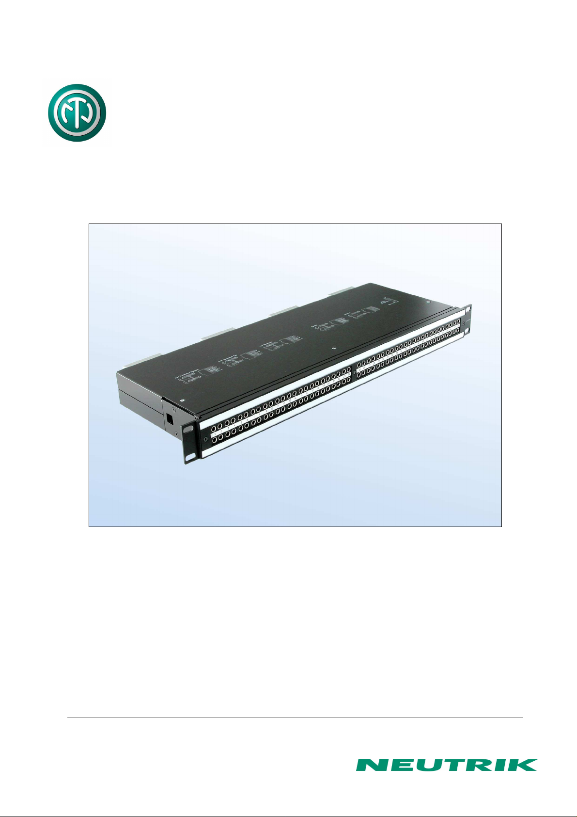
PATCH PANEL | 96 Bantam (TT) Jacks,
EDAC 90-pin termination
NEUTRIK AG NEUTRIK Zürich AG NEUTRIK (UK) Ltd. NEUTRIK USA INC. NEUTRIK Tokyo Ltd. NEUTRIK France NEUTRIK Vertriebs GmbH
Liechtenstein Switzerland Great Britain USA Japan France Germany/Netherlands/Austria
Tel.: +423/237 24 24 Tel.: +41 44/736 5010 Tel.: +44 1983/811 441 Tel.: +1 732/901 9488 Tel.: +81 3/3663 4733 Tel.: +33 1/4131 6750 Tel.: +49 8131/28 08 90
Fax: +423/232 53 93 Fax: +41 44/736 5011 Fax: +44 1983/811 439 Fax: +1 732/901 9608 Fax: +81 3/3663 4796 Fax: +33 1/4131 0511 Fax: +49 8131/28 08-30
www.neutrik.com
Draft. Nr.: BDA90-1/ 3102M0801
Update: 03.08.2009
Data subject to change without prior notice. ©2007 NEUTRIK . ALL RIGHTS RESERVED.
NPPA
-TT-
E90 Instruction Manual
Index
1. Electrical configuration................................................................................................. 3
2. Replacement of Jack Pairs .......................................................................................... 4
3. Reconfiguration by hand .............................................................................................. 5
4. Grounding variations ................................................................................................... 6
5. Wiring diagram ............................................................................................................ 8
6. Cable retention to the unit.......................................................................................... 10
7. Channel identification ................................................................................................ 10
8. Technical data ........................................................................................................... 13
9. Ordering Information .................................................................................................. 14
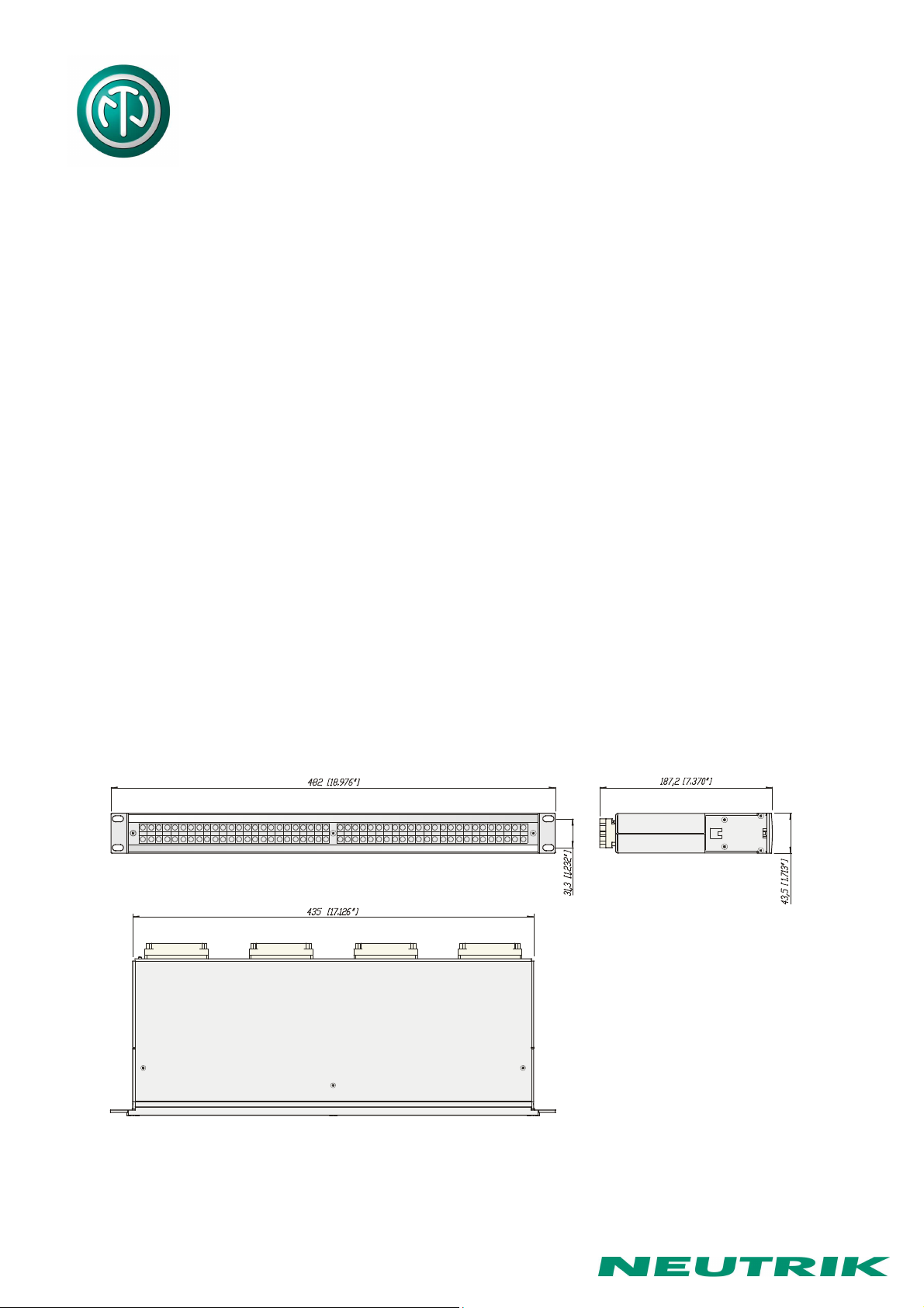
Dimensional Drawings “Easy Patch” NPPA-TT-E90
Page 2 of 14
NPPA
-TT-
E90 Instruction Manual
1. Electrical configuration
The Neutrik ”Easy Patch” Patch Panel is fitted with high quality, long life NJ3TTA gold plated
double contact jacks (2 x 48). This Patch Panel is an innovative and compact patching system
(just 1 U high) for 19” rack mounting. Robustly housed in black coated steel shell and featuring
precision aluminum fittings it is built to last. The Neutrik "Easy Patch” is suitable for analog and
digital audio signals.
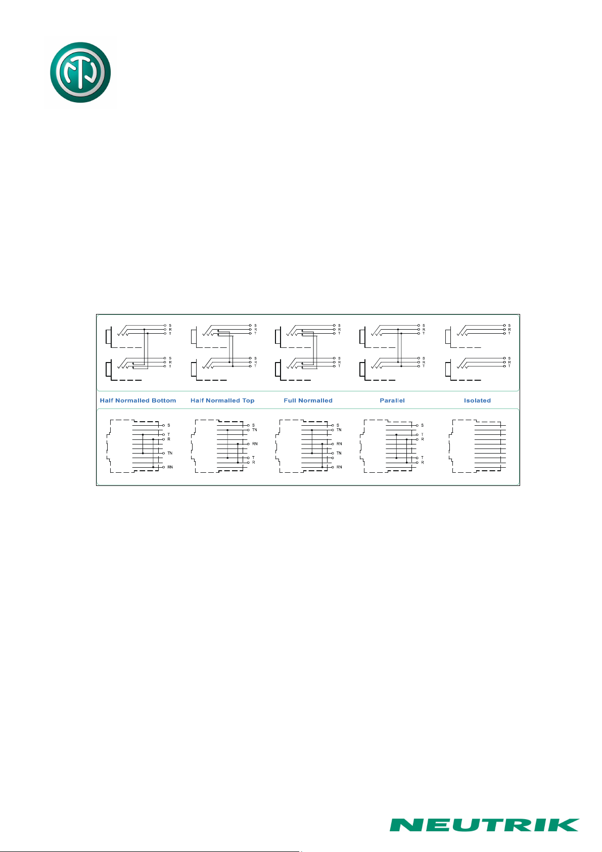
The ”Easy Patch” is available in five normalling configurations (fully loaded).
• half normalled bottom row
• half normalled top row
• full normalled
• parallel
• isolated
Configuration Chart
Furthermore individual jack pairs can be changed to combine various normallings within one
panel quickly and without fuss. This is even possible while the panel is "on air". For this we offer
pre-configured jack pairs (NJ3TTA-4-*).
In case of emergency the normalling for individual jack pairs can be changed by the use of
normalling bars. Normalling bars to change the normalling of 4 channels are included.
Page 3 of 14
NPPA
-TT-
E90 Instruction Manual
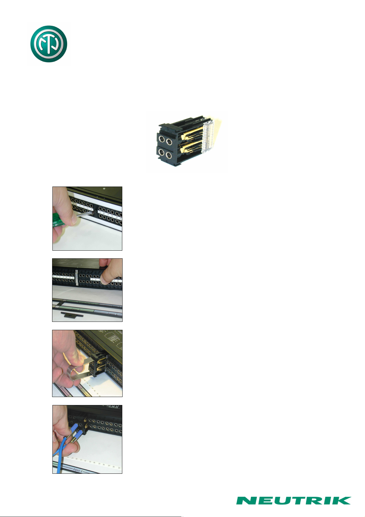
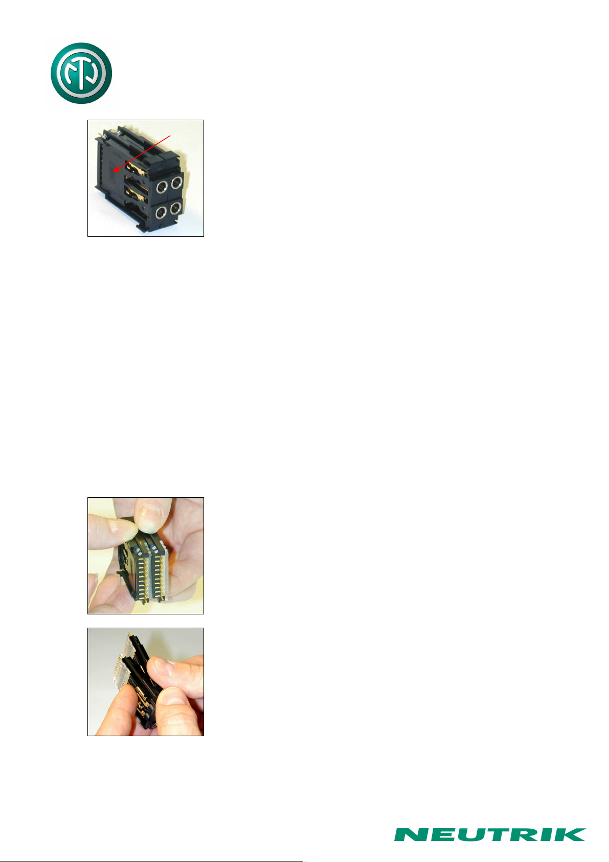
2. Replacement of Jack Pairs
Each individual jack pair can be exchanged quickly and without fuss even while the panel is "on
air". For replacement simply remove the easy accessible jack pairs.
Module consisting of 2 Jack Pairs
Remove Front Panel by unscrewing the 3 black cross-recessed
screws (M3x8 Taptite), remove the two side-stops.
Push out the channel identification strips.
Pull one module out of the casing using the supplied
disassembling pliers
Alternatively the jack pairs may be pulled out by the use of two
Bantam plugs (diagonally plugged in).
Page 4 of 14
NPPA
-TT-
E90 Instruction Manual
The two jack pairs have to be re-assembled in the right way so
that the thicker body marked “left” is put on the left side with
the mark outside and readable.
To complete, push the new jack pairs into the casing again with the mark on the left side (If
more than one module are removed always assemble from the center to the right or left side
and be careful that the keys on the left side of the jack pairs find their guiding slots. If all jack
pairs are removed start at the casing support in the center and assemble to the right and left
side). Slide in again the channel identification strips (best from the outside inwards) and fix the
front panel with the black cross-recessed screws. Don’t forget to insert the side-stops before
fixing the screws (see page 10).
3. Reconfiguration by hand
Please note, in case of emergency the normalling can by changed by hand by the use of
normalling bars. For easy and safe modification work we recommend our preconfigured jack
pairs (NJ3TTA-4-*).
The two jack pairs are separated by spreading apart the rear
parts to unlock the fixing mechanism till it is possible...
...to slide the jack pairs against each other in axial direction.
Page 5 of 14
 Loading...