

Page 1
User Manual
NA2-IO-DPRO
for Mic, Line, AES I/O
to DANTETM Interface
Page 2

Imprint
Subject to change due to advances in technology! This user manual corresponds to the level of
technology at the time the product was delivered and not the current stage of development at
Neutrik.
If any pages or sections of this user manual are missing, please contact the manufacturer at the
address listed below.
Copyright
This user manual is protected by copyright. The user manual must not be duplicated, reproduced,
microfilmed or translated, nor must it be converted to be saved and processed in IT systems,
neither in the form of excerpts nor in full, without the express written authorization of Neutrik.
Copyright by: © Neutrik® AG
Document Identification
Document No: BDA 573
Version: V1 2019/08
Language: English
Original language: English
Each user manual in a different language is a translation of the operating manual in English.
Manufacturer
Neutrik® AG
Im alten Riet 143
9494 Schaan
Liechtenstein
Phone: +423 2372424
Fax: +423 2325393
E: neutrik@neutrik.com
www.neutrik.com
2 User Manual – DANTETM Adapter NA2-IO-DPRO | BDA 573 V1 2019/08
Page 3

Table of Contents
1 About this Document ..............................................4
1.1 Significance of the user manual .............................4
1.2 Designations .........................................................4
1.3 Explanation of symbols .........................................5
1.3.1 Symbols in illustrations ....................................5
1.4 Target group ......................................................... 5
2 Safety ........................................................................6
2.1 Warning information and signal words ..................6
2.2 Warning symbols ..................................................6
2.3 Important regulatory notes ...................................6
2.3.1 Declaration of conformity ................................7
2.4 Important safety instructions .................................7
2.5 Intended use .........................................................7
2.6 Foreseeable improper use .....................................7
3 Components and Accessories .................................8
4 Description of the Product ......................................9
4.1 What is the DPRO Adapter? ................................... 9
4.2 Device ..................................................................9
4.3 Connections and displays ......................................9
4.3.1 Overview front ................................................9
4.3.2 Overview rear ...............................................10
4.3.3 Modes and switching logic of the
DPRO Adapter ....................................................... 11
4.4 DPRO Controller..................................................11
4.4.1 General overview .......................................... 11
4.4.2 Create Preset page ........................................15
4.4.3 Load Preset page .......................................... 16
4.4.4 Load Preset mismatch page ...........................17
4.4.5 Reset Devices window ..................................18
4.4.6 About Device (Device Settings) window ........18
4.4.7 Network Settings window ............................. 19
4.4.8 Firmware Upgrade window ........................... 19
4.4.9 About Software window ...............................20
5 Operation ...............................................................21
5.1 Preparations ........................................................ 21
5.2 Connecting devices with the DPRO Adapter ....... 21
5.2.1 Power setup using a switch with PoE support 22
5.2.2 Power setup using a switch without PoE sup-
port ....................................................................... 22
5.3 Applications ........................................................23
5.3.1 Redundant Mode ..........................................23
5.3.2 Switched Mode (Daisy-chained) ....................23
5.4 Linking devices with the DanteTM controller..........24
5.4.1 Enabling a Dante
TM
link ..................................24
5.5 DPRO Controller App .......................................... 24
5.5.1 Downloading and installing DPRO Controller
App ....................................................................... 24
5.5.2 Connecting devices with the app ..................25
5.5.3 Selecting the device to edit ...........................25
5.5.4 Setting input parameters ............................... 25
5.5.5 Setting output parameters ............................26
5.5.6 Presets .......................................................... 27
5.5.7 Identify device ...............................................30
5.5.8 Reset device ..................................................31
5.5.9 Network Settings .......................................... 32
5.5.10 Firmware Upgrade .......................................33
5.6 Accessories assembly instructions ........................ 34
5.6.1 Mounting brackets ........................................34
5.6.2 Rack panel ....................................................35
6 After Operation .....................................................36
6.1 Dismounting devices ...........................................36
6.2 Transporting .......................................................36
6.3 Storage ...............................................................36
6.4 Cleaning and care ...............................................36
6.5 Maintenance and repair ......................................36
6.6 Disposal .............................................................. 37
7 Appendix ................................................................ 38
7.1 Technical specifications ........................................ 38
7.2 PoE (Power over Ethernet) ...................................40
7.2.1 Definitions .....................................................40
7.2.2 PoE Standards ...............................................40
7.2.3 Classes and discovery process ........................40
3User Manual – DANTETM Adapter NA2-IO-DPRO | BDA 573 V1 2019/08
Page 4
About this Document
1 About this Document
This user manual provides an overview of the necessary operation steps and settings on the product.
1.1 Significance of the user manual
This user manual is an integral component of the product and part of the product's safety
concept.
T Make sure that all persons who work with the product have fully read and also
understood this user manual.
T Observe all instructions exactly, especially the safety instructions.
This user manual contains important information on safely and properly operating the
product.
T Keep this user manual in the immediate vicinity of the product so personnel have access
to it at all times.
T Pass this user manual on to every user, e.g., by lending it, or to the future owner of the product.
T If this user manual is lost or damaged, a copy of it can be downloaded from the Neutrik's
website (www.neutrik.com).
1.2 Designations
Designation Explanation
DPRO Adapter DPRO Adapter NA2-IO-DPRO; to ensure the text is easy-to-read, the
device is hereinafter referred to as DPRO Adapter.
DanteTM audio
networking
PoE Power over Ethernet; the device is supplied with power via the network
Peripheral devices Any device that can be connected to the DPRO Adapter: audio sources
Audio source Any device that emit an audio signal
Audio sink Any device that receives audio signals, such as loudspeakers, audio
DanteTM audio networking (hereinafter referred to as DanteTM) DanteTM
stands for Digital Audio Network Through Ethernet and is an audio
network protocol developed by the Australian company Audinate. DanteTM
delivers uncompressed, multi-channel, low-latency digital audio over a
standard Ethernet network using Layer 3 IP packets.
connection.
(transmitters) and audio sinks (receivers)
systems (amplifiers, mixing consoles, etc.)
4 User Manual – DANTETM Adapter NA2-IO-DPRO | BDA 573 V1 2019/08
Page 5
1.3 Explanation of symbols
Uniform safety instructions, symbols, terms and abbreviations were used to make this user manual
easier to understand. The following symbols designate instructions that are not relevant to safety,
but make the operating manual easier to understand.
O The preconditions for an action are depicted with this symbol. Complete the items as listed be-
fore carrying out the action steps that follow.
T Action steps are designated by this symbol. Carry out the action steps in the order they are
presented.
The result of the action or the reaction of the product to the action are depicted with this
symbol.
• Lists without a mandatory sequence are presented as a list with this bullet.
1. Numbered listings are displayed in this manner.
(1) Refers to a position in an illustration.
Wherever you see this symbol, you will find useful information for safe, trouble-free operation of the product.
1.3.1 Symbols in illustrations
About this Document
Symbol Explanation
1
1
Image position
Action steps numbered in an illustration.
Carry out the action steps in the order they are presented.
Only carry out these tasks when using OS X.
Only carry out these tasks when using Windows.
1.4 Target group
This user manual is intended for sound engineers and professional personnel who have detailed
experience in sound and event technology.
5User Manual – DANTETM Adapter NA2-IO-DPRO | BDA 573 V1 2019/08
Page 6
Safety
2 Safety
2.1 Warning information and signal words
Special warning information regarding potential dangers inherent in a particular action are presented before instructions for an action. The warnings are ranked as follows:
w CAUTION
Potential risk of danger!
This type of warning points out a situation that could result in minor or moderate injuries.
T Minor injuries may result if this warning is ignored.
w NOTE
Potential risk of property damage!
This type of warning points out a situation that could result in damage to the device and its
components.
T Property damage may result if the warning is ignored.
2.2 Warning symbols
Symbol Warning
General warning
Warning of hearing impairment
2.3 Important regulatory notes
This equipment has been tested and found to comply with the limits for a Class B digital device,
pursuant to Part 15 of the FCC Rules. These limits are designed to provide reasonable protection
against harmful interference in a residential installation. This equipment generates, uses and may
radiate radio frequency energy and, if not installed and used in accordance with the instructions,
may cause harmful interference to radio communications. However, there is no guarantee that
interference will not occur in a particular installation. If this equipment does cause harmful interference to radio or television reception, which can be determined by turning the equipment off
and on, the user is encouraged to try to correct the interference by attempting one or more of the
following measures:
• Reposition or relocate the receiving antenna.
• Increase the distance between the equipment and receiver.
• Connect the equipment to an outlet on a circuit different from to the one that the receiver is
connected to.
• Consult the dealer or an experienced radio/TV technician for help.
w NOTE
Changes or modifications made to this equipment not expressly approved by Neutrik may void
the FCC authorization to operate this equipment.
6 User Manual – DANTETM Adapter NA2-IO-DPRO | BDA 573 V1 2019/08
Page 7

2.3.1 Declaration of conformity
The device meets all the relevant EU directives and therefore has the CE and EAC marking. The
Declaration of Conformity may be viewed at www.neutrik.com/en/approvals-and-certificates.
2.4 Important safety instructions
Avoid property damage to the DPRO Adapter due to unsuitable operating and environmental conditions:
• Never immerse in water.
• Protect from strong sunlight.
• Never install the device near heat sources such as radiators, heating units, ovens or stoves.
• To avoid overheating, never cover the device.
• Protect the device from impact and above all, from falling from poles, stages, tables or furniture.
Repair
w NOTE
Property damage due to improper repair!
Safety
The DPRO Adapter does not contain any parts that you can repair yourself. Opening or repairing
the devices on your own may result in severe damage to the device.
T Do not open the housing of the DPRO Adapter under any circumstances.
T Do not change any parts yourself.
T Only have the DPRO Adapter repaired by a authorized specialist dealer.
Information for operation
T Ensure that the ambient conditions specified for the DPRO Adapter are observed during
operation.
T Do not use the DPRO Adapter if it is not functioning properly, has fallen or been damaged, has
become wet or if parts of it have been immersed in water.
T If disruptions occur during operation:
Immediately disconnect the DPRO Adapter from audio sources and/or audio sinks.
T Do not operate the DPRO Adapter in environments where flammable or explosive materials,
gases or vapors are present or might occur.
2.5 Intended use
The DPRO Adapter is designed for converting the signal of an analog LINE/MIC or digital AES/EBU
audio signal into a DanteTM signal. DanteTM signals can also be converted into analog LINE signals.
2.6 Foreseeable improper use
The DPRO Adapter is not suitable for use outdoors and in potentially explosive atmospheres.
7User Manual – DANTETM Adapter NA2-IO-DPRO | BDA 573 V1 2019/08
Page 8
Components and Accessories
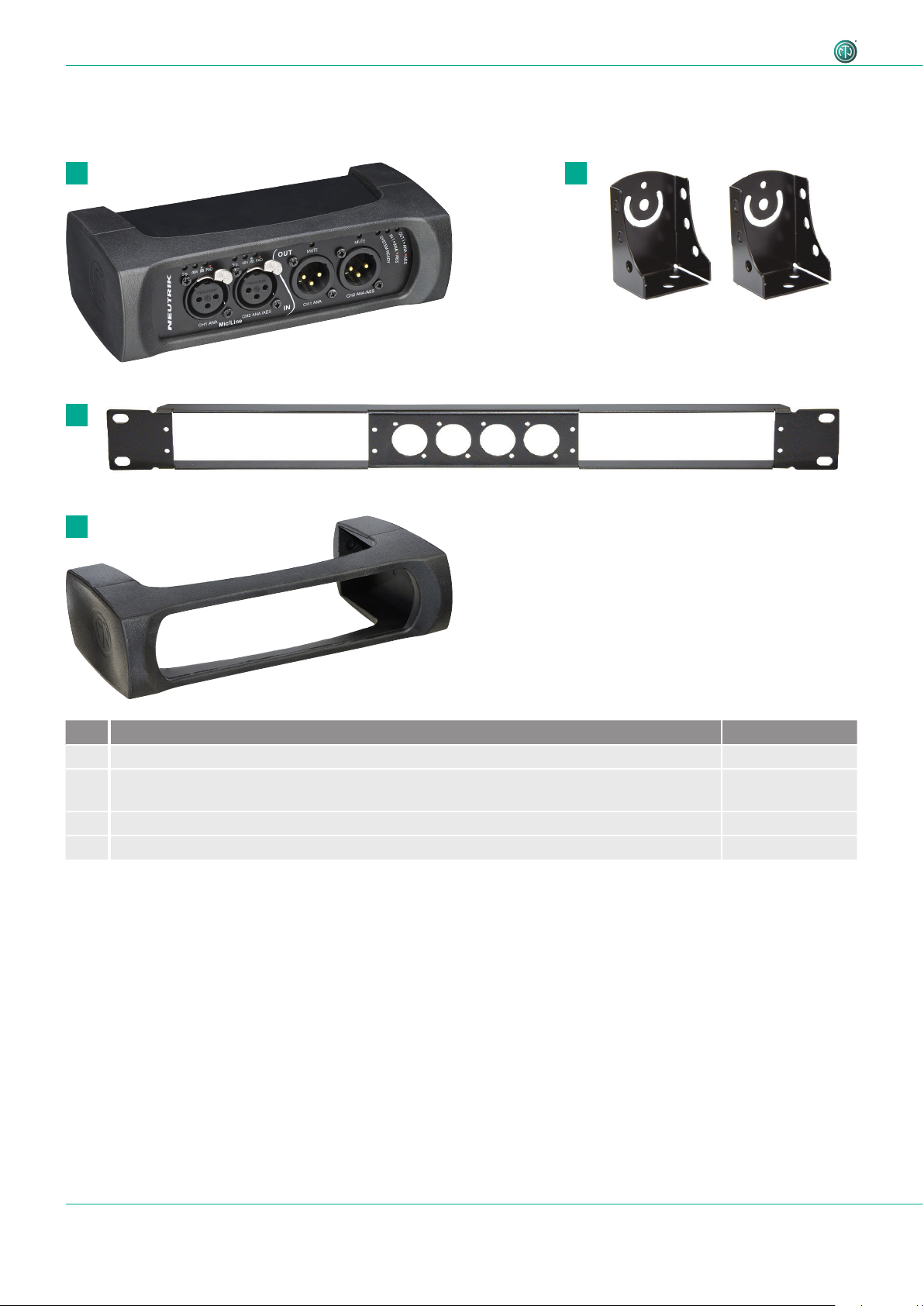
3 Components and Accessories
The device and the accessories can be ordered separately.
1 2
3
4
Pos. Description Item no.
1 DPRO Adapter (device) NA2-IO-DPRO
2 Mounting brackets
(Kit includes 2 brackets, 2 fixing screws, 2 torx screws and 2 spacers)
3 Rack panel NRP1RU-2 A
4 Removable rubber protection NA-RC
NA-MB-KIT
8 User Manual – DANTETM Adapter NA2-IO-DPRO | BDA 573 V1 2019/08
Page 9
Description of the Product
4 Description of the Product
4.1 What is the DPRO Adapter?
The DPRO Adapter is a 2IN, 2OUT breakout box designed to connect legacy audio equipment to
the Dante network. It features high-quality microphone preamps and 2 Dante ports for either redundant setup or daisy chaining. Audio parameters are adjusted by the DPRO Controller app.
All the connectors are lockable and, together with the removable rubber protector, offer a reliable
solution for tough stage conditions. With optional mounting brackets or a rack panel, the box can
be mounted below tables, in floor boxes, racks or on the truss.
4.2 Device
1
4.3 Connections and displays
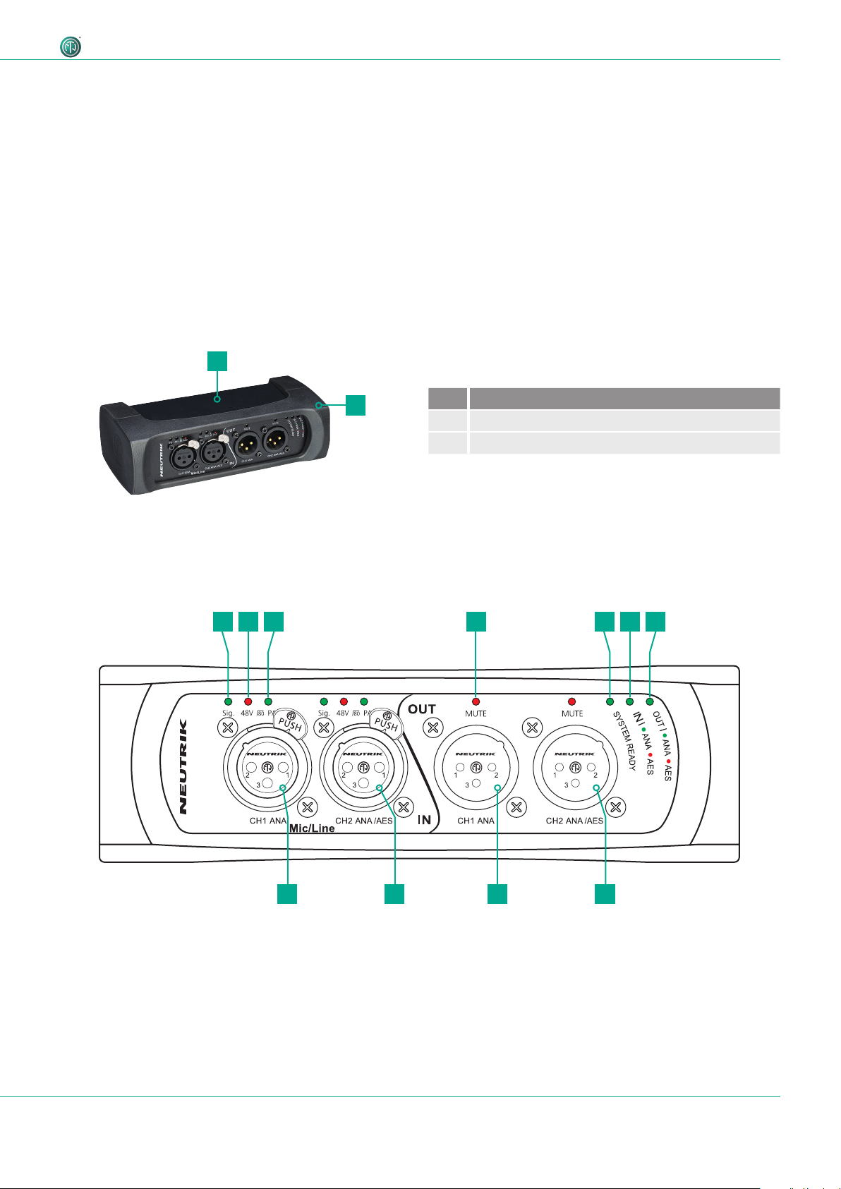
4.3.1 Overview front
1 52 4 63 7
2
Pos. Description
1 Sheet metal housing
2 Rubber protection (removable)
81011 9
9User Manual – DANTETM Adapter NA2-IO-DPRO | BDA 573 V1 2019/08
Page 10
Description of the Product
Pos. Description
1
Signal Present LED
Indicates the signal status.
• LED lights up green/yellow/red: signal available,
color indicates the signal level, see section
"Meter bar" on page 15.
• LED off: no signal.
2
Phantom power 48V LED
Indicates, if Phantom power is active.
• LED lights up red: Phantom power active.
• LED off: Phantom power not active.
3
HPF/Pad LED
Indicates, if HPF or Pad is active.
• LED lights up red: Pad
• LED lights up green: HPF
• LED flashs green and red: Pad and HPF active.
4
Output MUTE LED
Indiates, if output is muted.
• LED lights up red: Mute active.
• LED off: Mute not active.
Pos. Description
5
System Ready LED
Indicates the device's system status.
• LED lights up red: system is starting.
• LED lights up green: system is ready.
6
Input type LED
Indicates the device input status.
• LED lights up green: Analog mode.
• LED lights up red: Digital mode.
7
Output type LED
Indicates the device output status
• LED lights up green: Analog mode.
• LED lights up red: Digital mode.
8
Balanced XLR output 2
• Output for analog/digital line signals.
9
Balanced XLR output 1
• Output for analog line signal only.
10
Balanced XLR input 2
• Input for analog/digital line signals.
11
Balanced XLR input 1
• Input for analog line signal only.
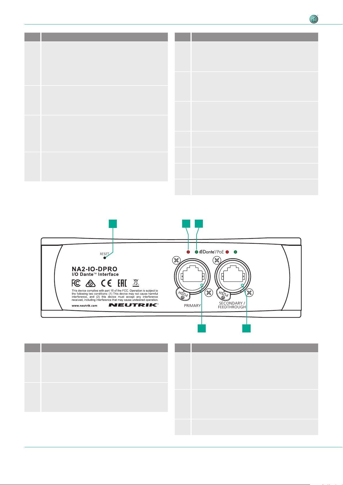
4.3.2 Overview rear
Pos. Description
1
Reset Button
• Press to delete all set parameters.
A detailed description see in section "5.5.8
Reset device" on page 32.
2
Link LED
Indicates the Ethernet connection status.
• LED is red: Ethernet connection is established.
• LED off: no Ethernet connection.
1
2 3
5
4
Pos. Description
3
Active LED
Indicates the data transmission status.
• LED flashes green: data transmission
established.
• LED off: no data transmission.
4
Secondary Network connection (RJ45)
Secondary Dante® Interface/Feedthrough/PoE
input (Redundant mode for standalone redundant
purpose, Switched mode for daisy-chaining)
5
Primary Network connection (RJ45)
Primary Dante® Interface/PoE input
10 User Manual – DANTETM Adapter NA2-IO-DPRO | BDA 573 V1 2019/08
Page 11
Description of the Product
4.3.3 Modes and switching logic of the DPRO Adapter
Switchable contacts in the DPRO adapter work in 2 ways:
• If the signal is analog, connect channel 1 and channel 2 (valid for input and output).
• If the signal is AES, connect channel 2 only (valid for input and output).
AES carries 2 separate signals over 1 physical cable. Therefore AES is occupying both channels and channel 1 becomes inactive. It's not possible to combine an analog signal on channel 1 and AES on channel 2, as this would
mean 3 separate signals are present. In this case channel 1 will have a priority and only the analog signal will be
present. This is valid for input and output.
w CAUTION
Danger of hearing damage!
Signal peaks may occur as a consequence of incorrect connections.
T Do not connect AES/EBU signal to input 1.
T Do not connect amplifiers or other analog devices to output 2 (AES) if there is no connection on
output 1 (ANA).
11User Manual – DANTETM Adapter NA2-IO-DPRO | BDA 573 V1 2019/08
Page 12
Description of the Product
4.4 DPRO Controller
DPRO Controller allows to control audio parameters, monitor the status of the device, recall, save and load presets. The
app is available for PC and Mac.
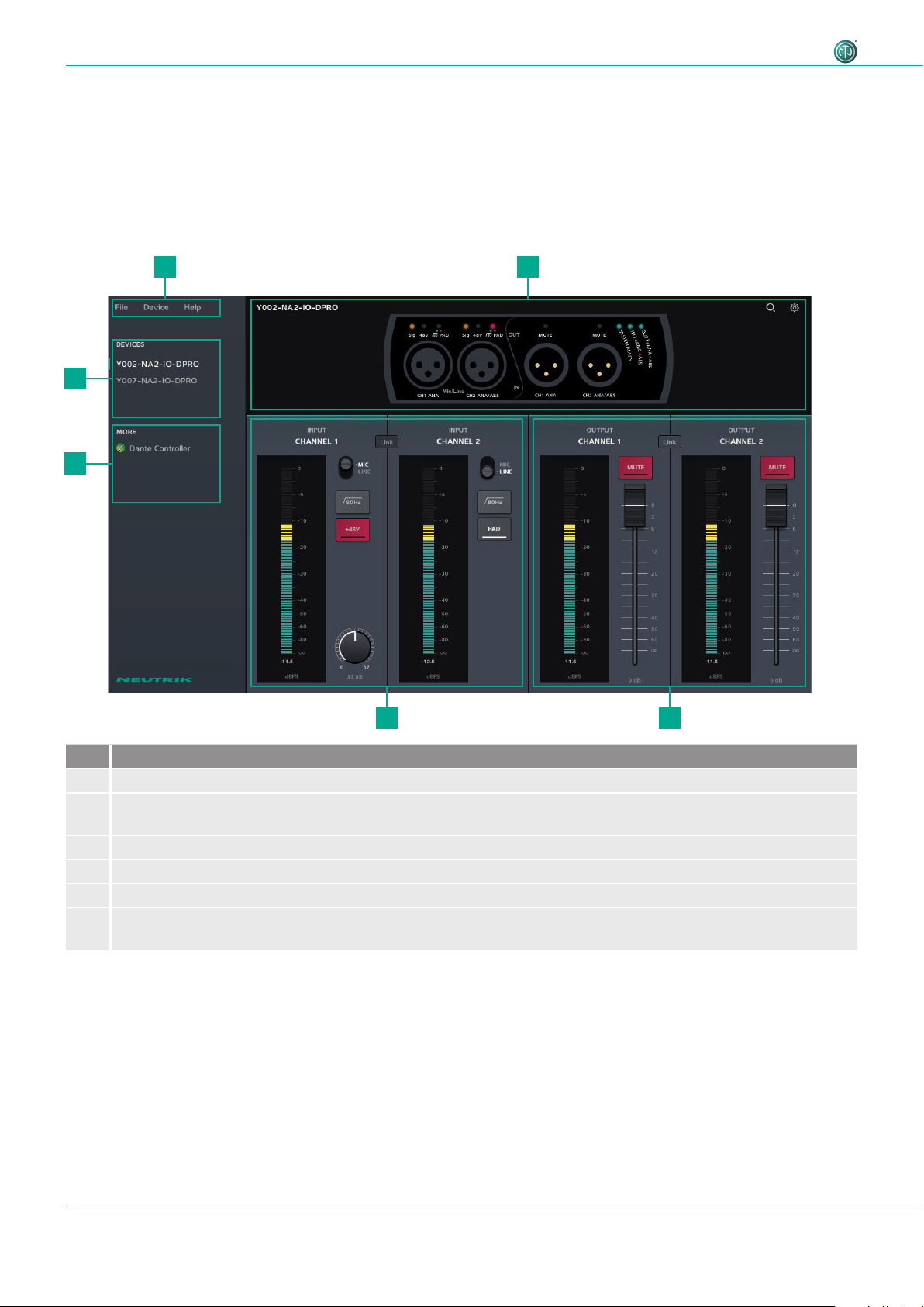
4.4.1 General overview
Analog inputs and outputs
1
6
5
2
Pos. Description
1 Menu
2 Device status
Shows the status of the selected device.
3 Output settings
4 Input settings
5 Link to Dante Controller
6 Connected devices
The selected device is marked with a green line on the left side.
34
12 User Manual – DANTETM Adapter NA2-IO-DPRO | BDA 573 V1 2019/08
Page 13
Description of the Product
Menu
Menu Option Shortcut Description
File Create Preset Ctrl/Cmd + N Opens a new Preset window.
Load Preset Ctrl/Cmd + L Applies created preset to devices.
Save As Preset Ctrl/Cmd + S Saves presets as .dap file on user's computer.
Quit Windows:
Quits the App.
Alt + F4, Ctrl + Q
Mac: Cmd + Q
Device Identify Device Ctrl/Cmd + I Identifies the selected device.
The LEDs on the front of the device flash red for 10 seconds.
Reset Device Deletes all set parameters on the selected device.
About Device Opens a window with general information of the selected
device.
Network Settings Opens a window with network settings.
Firmware Upgrade Opens a window with firmware information of the selected
device.
• Shows the version of the installed firmware.
• Install firmware upgrade.
Help About Software Opens a window with general information about the DPRO
Controller app and credits.
Further software functions/shortcuts
Option/Function Shortcut Description
Fader Ctrl/Cmd + click on
Fader jumps to 0.
fader
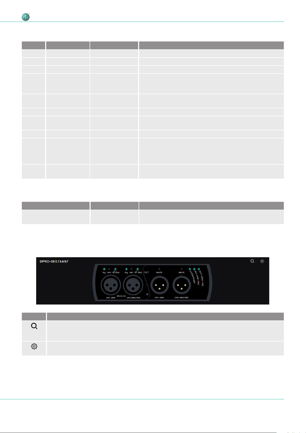
Device Status
This overview indicates the device status. The description of the LEDs can be found in chapter
"4.3.1 Overview front" on page 9.
Symbol Description
Identify device button
Click on the button to identify the selected device.
LEDs of XLR Inputs and XLR Outputs of the device flash up for 10 seconds.
Settings button
Click on the button to open the Settings window.
13User Manual – DANTETM Adapter NA2-IO-DPRO | BDA 573 V1 2019/08
Page 14

Description of the Product
Input Channels
Analog Inputs
Symbol/button Description
Normal Active
Microphone/Line Signal button
Indicates, if the signal has MIC or LINE input sensitivity.
Click on the button to change the sensitivity.
Position MIC: Microphone level
Position LINE: Line level
Low-cut filter button
Activates the low-cut filter for the input signal.
+48V
+48V
Phantom power button (only with MIC signal)
Activate this function if the microphone requires phantom power.
PAD button
Activate this function to apply 16 dB attenuation.
Link/Unlink button
Click this button to link or unlink the input/output signals.
Gain (only with MIC signal)
Adjusts the input sensitivity.
AES Inputs: Channel 1 becomes inactive
14 User Manual – DANTETM Adapter NA2-IO-DPRO | BDA 573 V1 2019/08
Page 15

Output Channels
0
5
0
0
5
2
0-3
0
0
6
0
8
0
d
F
S
Description of the Product
Analog Outputs AES Outputs: Channel 1 becomes inactive
Symbol/button Description
Normal Active
Mute button
Activate to mute the output signal.
Link/Unlink button
Click this button to link or unlink the input/output signals.
Meter bar
The Meter bar allows the signal level to be monitored on both input and output.
1
Pos. Description
1 Red area: 0 dBFS to -3 dBFS
2 Yellow area: -3 dBFS to -18 dBFS
2
-
-
3 Green area: -18 dBFS to infinite
3
-
-
-
-
4
B
15User Manual – DANTETM Adapter NA2-IO-DPRO | BDA 573 V1 2019/08
Page 16

Description of the Product
4.4.2 Create Preset page
With presets, settings of the devices can be stored for a later use. Presets can be also created and stored if no device is
connected or online. After adjusting the parameters, the preset can be saved as .dap file locally on the computer.
• Menu: File > Create Preset
• Shortcut: Ctrl/Cmd + N
Button / Screen text Description
CANCEL
SAVE PRESET
Close the window without saving the preset.
Save the preset as .dap file on the computer.
16 User Manual – DANTETM Adapter NA2-IO-DPRO | BDA 573 V1 2019/08
Page 17

4.4.3 Load Preset page
Load a preset from a .dap file from the computer.
• Menu: File > Load Preset
• Shortcut: Ctrl/Cmd + L
Description of the Product
Button / Screen text Description
Choose devices
Select the settings of one or more devices and load as preset.
Select all: Select all devices in the list.
Select none: Select no device in the list.
Checkbox: not selected
Checkbox: selected
PRESET PREVIEW
CANCEL
LOAD PRESET
Preview window of the settings which will be loaded with the preset.
Close the window without loading the preset.
Load preset with the selected device settings.
17User Manual – DANTETM Adapter NA2-IO-DPRO | BDA 573 V1 2019/08
Page 18

Description of the Product
Mismatch
Loading of the preset(s) was not successful. The mode of the preset do not match with device mode (e.g. Preset is saved
with AES mode, device works in analog mode). More information about the modes and switching logic please find in
section "4.3.3 Modes and switching logic of the DPRO Adapter" on page 11.
Icon Description
Warining Icon.
Indicates a mismatch.
18 User Manual – DANTETM Adapter NA2-IO-DPRO | BDA 573 V1 2019/08
Page 19

Description of the Product
4.4.4 Reset Devices window
This function resets the selected devices to factory settings. The reset function is described in section "5.5.8 Reset
device" on page 32.
• Menu: Device > Reset Device
Button / Screen text Description
CANCEL
RESET DEVICES
Close the window without resetting devices.
Reset selected devices to factory settings.
Select all: Select all devices in the list.
Select none: Select no device in the list.
not selected
selected
4.4.5 About Device (Device Settings) window
This window shows general information about the selected device.
• Menu: Device > About Device
Button / Screen text Description
Device name
Device Firmware
Dante Firmware
IP Address
FIRMWARE
UPGRADE
RESET DEVICE
Name of the selected device.
Current Neutrik firmware version installed on the device.
Current Dante firmware version installed on the device.
IP address of the device in the network.
Opens a window to upgrade the Neutrik's firmware on the device.
Reset device to factory settings.
19User Manual – DANTETM Adapter NA2-IO-DPRO | BDA 573 V1 2019/08
Page 20

Description of the Product
4.4.6 Network Settings window
Button / Screen text Description
AUTOMATIC
MANUAL
IP Adress
Static IP Address
New Static IP
Address
REBOOT NOW
CANCEL
SET STATIC IP
ADDRESS
The device obtains the IP address from DHCP server or locally from the computer.
The device's IP address can be entered manually.
IP address obtained from DHCP or local computer. Active, if AUTOMATIC is active.
Entered IP address by user. Checked IP address is active.
Enter a new static IP address by clicking the icon.
Reboots the device.
Close the window without any change.
Set the chosen static IP adress.
4.4.7 Firmware Upgrade window
Upgrade the Neutrik firmware on the device.
• Menu: Device > Firmware Upgrade
Button / Screen text Description
[Device Name]:
Current Firmware
Version X.X
Select Firmware
CANCEL
UPGRADE NOW
Upgrading
Firmware to
Version X.X
Firmware upgrade
completed
sucessfully
Information about the current device firmware.
Select the downloaded upgrade file.
Close the window without upgrading firmware.
Install firmware from the selected upgrade file.
Progress bar informs about the firmware upgrade progress.
Information that firmware upgrade is complete. Device will reboot after sucessful upgrade.
20 User Manual – DANTETM Adapter NA2-IO-DPRO | BDA 573 V1 2019/08
Page 21

4.4.8 About Software window
General information about the app.
• Menu: Help > About Software
Button / Screen text Description
Software Version
Version Date
Version of the DPRO Controller app.
Release date of the app version.
Description of the Product
21User Manual – DANTETM Adapter NA2-IO-DPRO | BDA 573 V1 2019/08
Page 22

Operation
5 Operation
5.1 Preparations
T Unpacking the DPRO Adapter.
T Save packaging for later transport and storage.
T Check the packaging and DPRO Adapter for visible damage.
T When visible damage to the packaging and/or delivered parts is detected:
Contact the salesperson or Neutrik sales partner.
T Do not use damaged devices under any circumstances.
5.2 Connecting devices with the DPRO Adapter
The DPRO Adapter can be connected to a DanteTM network via a standard 1 Gbit/s twisted-pair
Ethernet cable (CAT5e). This connection is responsible for the data transfer as well as for the power
supply. Depending on the cable length and shield, we do not recommend installing cables parallel
to power supply lines. To disconnect DPRO Adapter from power, the PSE or PSE’s (switch or injector) have to be disconnected from the power outlet.
The DPRO Adapter requires a switch that supports PoE (48 V). If a switch without
PoE support is available, a PoE injector (compatible with 802.3af or 802.3at) must
be connected in series.
w CAUTION
Danger of hearing damage!
Signal peaks may occur when an audio source or sink is connected.
T Before making connections, mute the signal path of the peripheral devices.
w CAUTION
Danger of hearing damage!
Signal peaks may occur as a consequence of incorrect connections.
T Do not connect AES/EBU signal to input 1.
T Do not connect amplifiers or other analog devices to output 2 (AES) if there is no
connection on output 1 (ANA).
Front Rear
22 User Manual – DANTETM Adapter NA2-IO-DPRO | BDA 573 V1 2019/08
Page 23

T Connect the device depending on the desired application:
Analog signal: Use channel 1 and Channel 2.
AES signal: Use channel 2.
T Connect the DPRO Adapter to the PoE switch using a network cable.
T If the switch does not support PoE:
Use a PoE injector.
LEDs light up once the DPRO Adapter is supplied with power via the switch or the PoE injector.
The DPRO Adapter is ready for operation.
Set up the desired audio connection with the "Dante
TM
controller" software.
5.2.1 Power setup using a switch with PoE support
Audio connection
Network connection
Operation
The DPRO Adapter forwards information to the PoE switch indicating that it is a "Class 2"
device to ensure the correct power supply.
5.2.2 Power setup using a switch without PoE support
PRIMARY
For power and data redundancy, use 2x passive PoE injectors. Because they do not use the discovery process, switching between primary and secondary will not result in a short loss of audio. More
information about PoE please find in section "7.2 PoE (Power over Ethernet)" on page 41.
Do not use two different passive PoE injectors (such as from different manufacturers), because this might cause a short circuit and make the device inoperable.
23User Manual – DANTETM Adapter NA2-IO-DPRO | BDA 573 V1 2019/08
Page 24

Operation
5.3 Applications
5.3.1 Redundant Mode
In Redundant mode, two copies of all the Dante
TM
information (audio, clock etc.) are sent across in
two separate networks to ensure uninterrupted signal flow in case one network goes down.
Audio connection
Network connection
5.3.2 Switched Mode (Daisy-chained)
In the Switched mode, you can daisy-chain several devices to increase channel count. Only passive
injectors are able to deliver steady power to all the daisy-chained units. Up to 2 devices can be
daisy-chained.
For daisy-chaining, use only a PoE Injector with no
class.
24 User Manual – DANTETM Adapter NA2-IO-DPRO | BDA 573 V1 2019/08
Page 25

5.4 Linking devices with the DanteTM controller
The DanteTM controller is a free software application that enables routing of audio signals and
configuring devices in a DanteTM network. Setting up a DanteTM network is very easy. The DanteTM
controller offers automatic device detection, one-click signal routing and user-editable device and
channel labeling.
The software together with tutorials and guides are available on the Audinate website
(www.audinate.com).
Operation
5.4.1 Enabling a Dante
T Download and install the "Dante
TM
link
TM
Controller"
software. (www.audinate.com).
T Connect the computer to the switch using a standard
network cable.
T Run the "Dante
T In the routing menu, click the + symbols of the devices.
T Establish the desired link.
TM
Controller" software.
The DPRO Adapter is displayed in the "DanteTM Controller" as a NA2DPRO by default, followed
by a suffix with the last 6 digits of the MAC address. This name can be customized for each device
in the DanteTM controller.
The "DanteTM Controller" software is used only to set up the audio connection (routing) between
devices and to configure the subscribing devices.
The devices are controlled in the DPRO Controller App.
5.5 DPRO Controller App
DPRO Controller allows user to control audio parameters, monitor the status of the device, recall,
save and load presets. The app is available for PC and Mac.
5.5.1 Downloading and installing DPRO Controller App
DPRO Controller App is available for PC and Mac, free of charge.
Please review the system requirements in the technical data before installing the app.
T Download the app on the Neutrik website: www.neutrik.com/en/support/downloads.
Installation on Windows
T Execute the downloaded .exe file and follow the installation steps.
The installation wizard creates an entry in Start menu and a link on your Desktop.
Installation on OS X
T Execute the downloaded .dmg file and follow the installation steps.
The DPRO Controller App is installed on computer. DPRO Controller
app icon
25User Manual – DANTETM Adapter NA2-IO-DPRO | BDA 573 V1 2019/08
Page 26

Operation
5.5.2 Connecting devices with the app
T Connect the devices as required.
T Start up the DPRO Controller.
The devices are connected with DPRO Controller automatically.
5.5.3 Selecting the device to edit
1
T In the connected devices list (1), click on the device name.
The selected device is marked with a green line on the left side.
5.5.4 Setting input parameters
T Change MIC/LINE:
Click the MIC/LINE button.
T Activate/deactivate the -16 dB attenuator:
Click the PAD button.
T Activate/deactivate the low-cut filter:
Click the 80Hz button.
T Activate/deactivate phantom power:
Click the +48V button.
T Adjust gain:
Click and hold the gain knob and move the mouse.
T Link/unlink input channels
Click the Link/Unlink button.
26 User Manual – DANTETM Adapter NA2-IO-DPRO | BDA 573 V1 2019/08
Page 27

5.5.5 Setting output parameters
Operation
T Mute/unmute channel:
Click the MUTE button.
T Adjust output volume:
Click and hold the fader button and move the mouse up or
down.
T Jump fader to 0:
Hold Ctrl/Cmd and click on the fader.
27User Manual – DANTETM Adapter NA2-IO-DPRO | BDA 573 V1 2019/08
Page 28

Operation
5.5.6 Presets
Presets allow user to save the settings of the devices that are connected to the app.
Create preset
T Click in the menu File > Create Preset... or use the shortcut Ctrl/Cmd + N.
The Create a new preset window appears.
T In the drop down menu, select the Input Mode and the Output Mode (None, Analog, AES)
depending on your application.
T Set your parameters.
T Click the SAVE PRESET button to save the preset as .dap file on your computer.
28 User Manual – DANTETM Adapter NA2-IO-DPRO | BDA 573 V1 2019/08
Page 29

Load Preset
T Click in the menu File > Load Preset... or use the shortcut or Ctrl/Cmd + L.
Operation
T Select a .dap file on your computer and click the Open button.
The Load preset window appears, which shows a preview of the preset to be loaded.
T In the drop down menu, select your devices.
T Check if the connected input/output signals matches with the preset modes (ANA /AES).
T To load the preset, click the LOAD PRESET button.
29User Manual – DANTETM Adapter NA2-IO-DPRO | BDA 573 V1 2019/08
Page 30

Operation
If Load Preset was not sucessful, the Load Preset mismatch screen appears.
T Check the device's input/output connections:
For analog signal use channel 1 and channel 2.
For AES signal use channel 2.
T Try to load the preset again or load another preset.
T If no matching preset is available, create a new preset.
More information about the modes and switching logic please find in section "4.3.3 Modes
and switching logic of the DPRO Adapter" on page 11.
30 User Manual – DANTETM Adapter NA2-IO-DPRO | BDA 573 V1 2019/08
Page 31

Save Preset
T Click in the menu File > Save As Preset... or use the shortcut Ctrl/Cmd + S.
Operation
T Enter a file name and click the Save button.
5.5.7 Identify device
T Select the device to identify.
Option 1:
T Click in the menu Device > Identify Device.
Option 2:
T Click the device status overview the identify device button .
Option 3:
T Use the shortcut Ctrl/Cmd + I.
The LEDs of the device flash up for 10 seconds.
31User Manual – DANTETM Adapter NA2-IO-DPRO | BDA 573 V1 2019/08
Page 32

Operation
5.5.8 Reset device
This option deletes all set parameters on the selected device. The device remains connected to the
app. There are two ways to reset the device.
Hardware reset
The hardware reset resets the following parameters:
• If MIC is active: Gain = 0 dB, HPF and Phantom power will be off.
• Network settings: Reset to Factory default (DHCP enabled).
• Outputs Mute will be off.
1
T On the back of the device, push the RESET button (1) for approx. 5 seconds.
Device is reset.
Software reset
The software reset resets the following parameters:
• If MIC is active: Gain = 0 dB, HPF and Phantom power will be off.
• Network settings: Reset to Factory default (DHCP enabled).
• Outputs Mute will be off.
T Click in the menu Device > Reset Device….
The Reset Devices window appears.
T Select the devices you want to reset.
T Click the RESET DEVICES button.
The devices are reset.
32 User Manual – DANTETM Adapter NA2-IO-DPRO | BDA 573 V1 2019/08
Page 33

5.5.9 Network Settings
The internal IP address can be set in 2 modes.
Automatic
The device obtains the IP address from DHCP server or locally from the computer.
Manual
The user defines the IP address manually.
Operation
T Choose the MANUAL mode.
A new line to enter New Static IP Address appears.
T Click the icon to enter the static IP address.
T Click the SET STATIC IP ADDRESS button.
T Reboot the device:
Click the REBOOT NOW button.
The static IP address is assigned to the device.
33User Manual – DANTETM Adapter NA2-IO-DPRO | BDA 573 V1 2019/08
Page 34

Operation
5.5.10 Firmware Upgrade
With the Firmware Upgrade function in the DPRO Controller app user can only upgrade the
Neutrik's firmware of the device. To upgrade the DanteTM Firmware, please use the DanteTM
controller
T Download the Firmware Upgrade on the Neutrik website:
www.neutrik.com/en/support/downloads.
T In the DPRO Controller app, select the device to upgrade.
Option 1:
T Click in the menu Device > Firmware Upgrade.
Option 2:
T Click the device status overview the device settings button .
The Device Settings window appears.
T Click the FIRMWARE UPGRADE button.
The Firmware Upgrade window appears.
T Click the Choose… button and select the downloaded upgrade file.
T Click the UPGRADE NOW button.
The device's firmware upgrade will be installed.
During the upgrade the progress bar shows the upgrade progress.
If the upgrade is completed, the message Firmware upgrade completed successfully appears.
The device starts rebooting.
34 User Manual – DANTETM Adapter NA2-IO-DPRO | BDA 573 V1 2019/08
Page 35

5.6 Accessories assembly instructions
w NOTE
Use only original Neutrik screws to prevent damage to the device.
5.6.1 Mounting brackets
The mounting brackets make it possible to mount the device in floor boxes, underneath tables, etc.
Scope of delivery
Assembly of the mounting brackets
Prepare the following tools:
O Torx Screwdriver (T10)
Operation
2 brackets 2 fixing screws 2 torx screws 2 spacers
1
T Remove the rubber protection.
3 4
2
T Mount a bracket, a spacer and a screw on the device as
shown on the picture.
T Tighten the screw with the scewdriver.
T Repeat these steps on the opposite side of the device.
T Mount the fixing screw as shown on the picture.
T Repeat these steps on the opposite side of the device.
T Turn the brackets as required for the mounting
situation.
T Tighten the fixing screw firmly.
35User Manual – DANTETM Adapter NA2-IO-DPRO | BDA 573 V1 2019/08
Page 36

Operation
5.6.2 Rack panel
Scope of delivery
1 rack panel
Assembling the rack panel
Prepare the following tools:
O Crosshead screwdriver
1 2
T Remove the rubber protection.
3
T Place the device in the rack panel.
T Fix the device with the four screws.
T Remove the 4 screws on the front of the device.
36 User Manual – DANTETM Adapter NA2-IO-DPRO | BDA 573 V1 2019/08
Page 37

6 After Operation
6.1 Dismounting devices
T Disconnect devices from audio sources/sinks.
6.2 Transporting
T Always transport devices and accessories in their original packaging.
6.3 Storage
T If devices are not used for a longer period:
Disconnect the device from the connected devices.
T Always store devices in a clean, dry location.
T Always protect devices from dirt, dust, heat, humidity and moisture.
6.4 Cleaning and care
After Operation
w NOTE
Danger of property damage due to improper cleaning!
T Disconnect device from all connections before cleaning.
T Never immerse device or accessory in water under any circumstances.
T Never spray device or accessory with liquids under any circumstances.
T Wipe the surfaces of the device and accessory with a soft cloth slightly moistened with a mild
soap solution.
T Never use aggressive, solvent-based or abrasive cleaning agents under any circumstances.
T Never use rough materials (e.g., cleaning cloths or sponges with a rough coating).
6.5 Maintenance and repair
The DPRO Adapter does not contain any parts that can be maintained or repaired by the user.
T Only have the DPRO Adapter repaired by a specialist dealer authorized by Neutrik.
T Check the DPRO Adapter regularly for visible damage to the housings, controls, connections,
cables and plugs.
T If damage is detected, do not use device under any circumstances.
T Immediately decommission the damaged device.
T Replace defective cables or accessories immediately.
37User Manual – DANTETM Adapter NA2-IO-DPRO | BDA 573 V1 2019/08
Page 38

After Operation
6.6 Disposal
T Dispose of the DPRO Adapter and accessories in accordance with the applicable local
regulations.
T Never dispose of electrical devices or electrical accessories such as cables, plugs,
batteries or components with household wastes under any circumstances.
T Dispose of packaging and packaging elements in accordance with the applicable local
regulations.
T Take device components made of plastic, metal or other recyclables for reclamation in
accordance with the applicable local regulations.
38 User Manual – DANTETM Adapter NA2-IO-DPRO | BDA 573 V1 2019/08
Page 39

7 Appendix
7.1 Technical specifications
DanteTM specifications
Channels 2 INPUTS (Line Level / Mic / AES / EBU)
2 OUTPUTS (Line Level / Mic / AES / EBU)
Supported sampling rates 44.1 / 48 / 88.2 / 96 kHz
Bit depth 16, 24 and 32 Bit
Latency based on user selection 0,25 ms (Dante)
Ethernet connection 1.000 BASE-T (supporting PoE)
Electrical specifications
Power consumption < 6 watts
Power supply 1.000 BASE-T (supporting PoE) or
PoE midspan power injector (according to IEEE 802.3af/at, class 2)
Appendix
Analog audio input
Equivalent input noise -128 dBu (67 dB Gain); A-weighted
Gain hub (3 dB Steps) 0 – 67 dB
Max. input level +24 dBu (PAD enabled)
+8 dBu (PAD disabled)
Input impedance > 7.5 kOhm, balanced
Frequency response 20 Hz to 20 kHz (± 0.5 dB)
Dynamic range > 112 dB, BW 22.4 kHz, A-weighted (input gain = min.)
Signal-to-noise ratio > 112 dB, BW 22.4 kHz, A-weighted
THD + noise < 0.005 % (20 Hz to 20 kHz, +4 dBu)
Crosstalk -100 dB, adjacent INPUT/OUTPUT channels (input gain = min.)
Analog audio output
Output impedance < 150 Ohm, balanced
Max. output level +24 dBu
Residual output noise -88 dBu, A-weighted
Frequency response 20 Hz to 20 kHz (± 0.5 dB)
Dynamic range > 112 dB, BW 22.4kHz, A-weighted
Signal-to-noise ratio > 112 dB, BW 22.4kHz, A-weighted
THD + noise < 0.005% (20 Hz to 20 kHz, +4 dBu)
Crosstalk -100dB, adjacent INPUT/OUTPUT channels (input gain = min.)
39User Manual – DANTETM Adapter NA2-IO-DPRO | BDA 573 V1 2019/08
Page 40

Appendix
Mechanical specifications
Weight 0.53 kg / 1.17 lbs
Dimensions
(with rubber protection)
L = 164 mm (6.4 inches)
B = 82 mm (3.2 inches)
H = 51 mm (2.0 inches)
Dimensions
(without rubber protection)
L = 151 mm (5.9 inches)
B = 66 mm (2.6 inches)
H = 41 mm (1.6 inches)
Operating environment Indoor
Operating temperature 0 °C to +50 °C
Storage temperature –40 °C to +150 °C
App Requirements
RAM min. 2 GB
Display resolution min. 1280 x 1024 px
Operating System Windows 7 or later
MAC OS X 10.12 or higher
40 User Manual – DANTETM Adapter NA2-IO-DPRO | BDA 573 V1 2019/08
Page 41

7.2 PoE (Power over Ethernet)
PoE stands for Power over Ethernet and describes a practice for using a single CAT5e (or higher) to
incorporate both power and data in the single cable.
Few advantages:
• Easy setup
• Single cable run up to 100 m
• Using PoE doesn’t require certified electrician as the power loads are small
• Existing network infrastructure can be used
7.2.1 Definitions
PD (Powered device) – device that is connected to PSE and thus is powered by it.
PSE (Power Sourcing Equipment) – device that provides power to PD, Switch or injector
PSE Types
In our case, we consider only following two types of PSE devices.
• PoE Switch: a switch that offers possibility to power PD. Switches use PoE classification.
• PoE Injector: typically a single port device for powering 1 PD. These exist with classification
(active) or without (passive).
The term class refers to a maximal power output (see table below).
Appendix
7.2.2 PoE Standards
These standards are part of IEEE 802.3 general standards.
802.3 af – defines PoE classes 0-3
802.3 at – uses the same classes, but introduces class 4 as well.
7.2.3 Classes and discovery process
Discovery is a process of PSE, determining the power requirements of the PD. Once PD and PSE are
connected, PSE sends out a short voltage impulse, reads the returned value and provides power
accordingly. This is valid for PSE with class (also called active).
No class (passive) PSE, acts as a classic power supply, hence no discovery is implemented, and PSE
supplies current at all times.
Class Typ e Power required by PoE class at the Powered Device (PD)w
1 802.3af 0.44 - 3.84 W
2 802.3af 3.84 - 6.49 W
3 802.3af 6.49 - 12.95 W
4 802.3at PoE+ 12.95 - 25.5 W
41User Manual – DANTETM Adapter NA2-IO-DPRO | BDA 573 V1 2019/08
 Loading...