

Neurotherm JK-3 User manual

NEUROTHERM
RADIO
FREQUENCY
MODEL
JK3
LESION
GENERATOR
OPERATORS
GENERAL
TECHNICAL
DESCRIPTION
3.1
INTRODUCTION
DATA
OPERATING
3.1.1
3.1.2
3.1.3
OF
SELECT
IMPEDANCE
STIMULATE
TABLE
CONTROL
PANEL
LAYOUT
MODE
OF
SWITCH
METER
SECTION
MANUAL
CONTENTS
1-1
2-1
3-1
3-1
3-2
3-3
3-4
3.1.4
3.2
3.3
CHECK
BACK
FRONT
AND
STERILISATION
LESION
PROCEDURES
MAINTENANCE
ACCEPTANCE
APPENDIX
EC
DECLARATION
YEAR
PULSED
2000
RF
CONFORMITY
DETAILS
LESION
PANEL
PANEL
TEST
PROCEDURES
TESTING
POWER
LAYOUT
LAYOUT
PROCEDURES
OF
CONFORMITY
SECTION
3-5
3-7
3-8
4-1
5-1
6-1
7-1
8-1
26
November
1998
Rev
3

Using
Introduction
There
patient
The
operating
the
NeuroTherm
are
times
but
the
Stimulation
correctly.
Preparation
Ensure
that
the
Contents
when
the
patient
Test
does
Kit
The
Stimulator
Red
Circular
Blue
Instructions
Stimulation
cannula
not
feel
Test
Kit
and
thermocouples
any
stimulation.
provides a positive
test
can
be
performed
Test
Kit
is
kept
sterile
cable
test
block
sterilising
for
tray
use
test
that
within
and
look
to
the
electrode
the
sterile
always
be
properly
and
RF
field.
available.
positioned
lesion
generator
in
the
are
Sterelisation
After
use
normally
Sterilize
Check
When
turn
LESION
Check
Ensure
place
Check
Plug
block
Switch
note
Thermocouple
the
green.
the
that
in
the
the
on
the
the
Instructions
the
Stimulation
available
by
autoclave
thermocouple
When
mode
Reference
the
the
patient
Stimulation
red
test
the
sterile
JK3
meter
cleansing
as
inserted
will
read
Plate
reference
check
lead
into
trolley.
into
STIMULATOIN
increases
Test
Kit
agent.
for
porous
1s
plugged
into
between
plate
is
the
IMPEDANCE.
the
JK3
up
to 2 Volts
should
materials.
into
the
cannula
35° and
properly
and
mode,
approximately.
be
cleaned
the
JK3
the
38°C.
connected.
the
other end
set
as
per
Maximum
the
red
LED
permitted
temperature
With
into
the
to
100
Hz
institutional
policy
temperature
labelled
reading
the
thermocouple
test
or 3 Hz,
THERMOCOUPLE
on
the
round
block.
turn
up
using
JK3
in
and
Place
the
amplitude
any
140°C.
TEST
cannula
the
will
or
in
in
test
and
Remove
end
With
This
of
the
is
the
the
proof
sterile
thermocouple
amplitude
positive
cannula.
Repositioning
If
all
is
correct
Continue
If a satisfactory
and
keep
ready
to
turn
patient.
When
the
with
to
reposition
threshold
the
stimulation
the
amplitude
stimulation
thermocouple
onto
the
turned
that
up a buzz
the
stimulation
Electrode
the
machine
until
the
patient
cannot
on
while
down
1s
felt
from
the
sterile
block.
(100
and
electrodes
feels
be
found
the
needle
or
off
as
properly
patient,
HZ)
or a tick
voltage
then
the
stimulation.
turn
up
is
slowly
soon
as
test
for
the
cannula
(3
Hz)
is
actually
the
the
being delivered
position
stimulation
moved
stimulation
the
sensory
1999
can
stay
in
will
be
heard.
of
the
cannula
voltage
around.
is
felt
as
Ensure
it
threshold
Using
the
place,
to
the
to
0.5
an
can
be
turning
Stimiziattoni
and
touch
tip
of
is
suspect.
Volt
(or | Volt)
assistant
painful
up
from
Pest
bot
the
the
1s
for
the
zero
NEUROTHERM
RADIO
FREQUENCY
MODEL
JK3
LESION
GENERATOR
1-1
OPERATORS
GENERAL
The
Neurotherm
features
The
the
discrete
It
is
Analogue
and
The
power
required
front
controls
area.
designed
rf
voltage,
lesion
and
INTRODUCTION
Radio
by
practioners
panel
has
been
via
sterilisable
for
safe
meters
stimulation
are
and
digital
generator
Frequency
ergonomically
knobs.
use
in a low
used
to
facilitate
displays
has
full
electronic
voltage.
Lesion
for
pain
Each
light
are
relief
designed
functional
x-ray
immediate
used
MANUAL
Generator
clinic
work.
and
has
allows
effect
theatre
environment.
visual
for
impedance,
interlocking
to
been
designed
the
clinician
of
the
device
interpretation
stimulate
prevent
is
of
voltage
accidental
to
offer
the
direct
defined
manipulation
within
temperature,
and
lesion
switching
full
range
rf
time.
to
of
of
it's
own
current
lesion
The
internal
approved
The
from
technicians
machine
other
compromise
settings
of
the
authorised
is
designed
for
manufacturers
the
safety
of
the
machine
by
use
with
could
patient,
have
been
the
company.
NeuroTherm
give
serious
and
would
factory
Thermocouple
errors
negate
set
and
in
the
the
warranty.
should
not
Probes.
temperature
be
adjusted
The
reading
use
except
of
probes
and
may
by
26
November
1998
Rev
3
NEUROTHERM
RADIO
FREQUENCY
MODEL
JK3
LESION
GENERATOR
2-1
OPERATORS
TECHNICAL
SIZE
Width
Height
Depth
WEIGHT
8.9Kg
ELECTRICAL
DATA
400
mm
(15.7")
172
mm
(6.8")
430
mm
(16.9")
(19.5lbs)
MANUAL
UK
USA
230
110
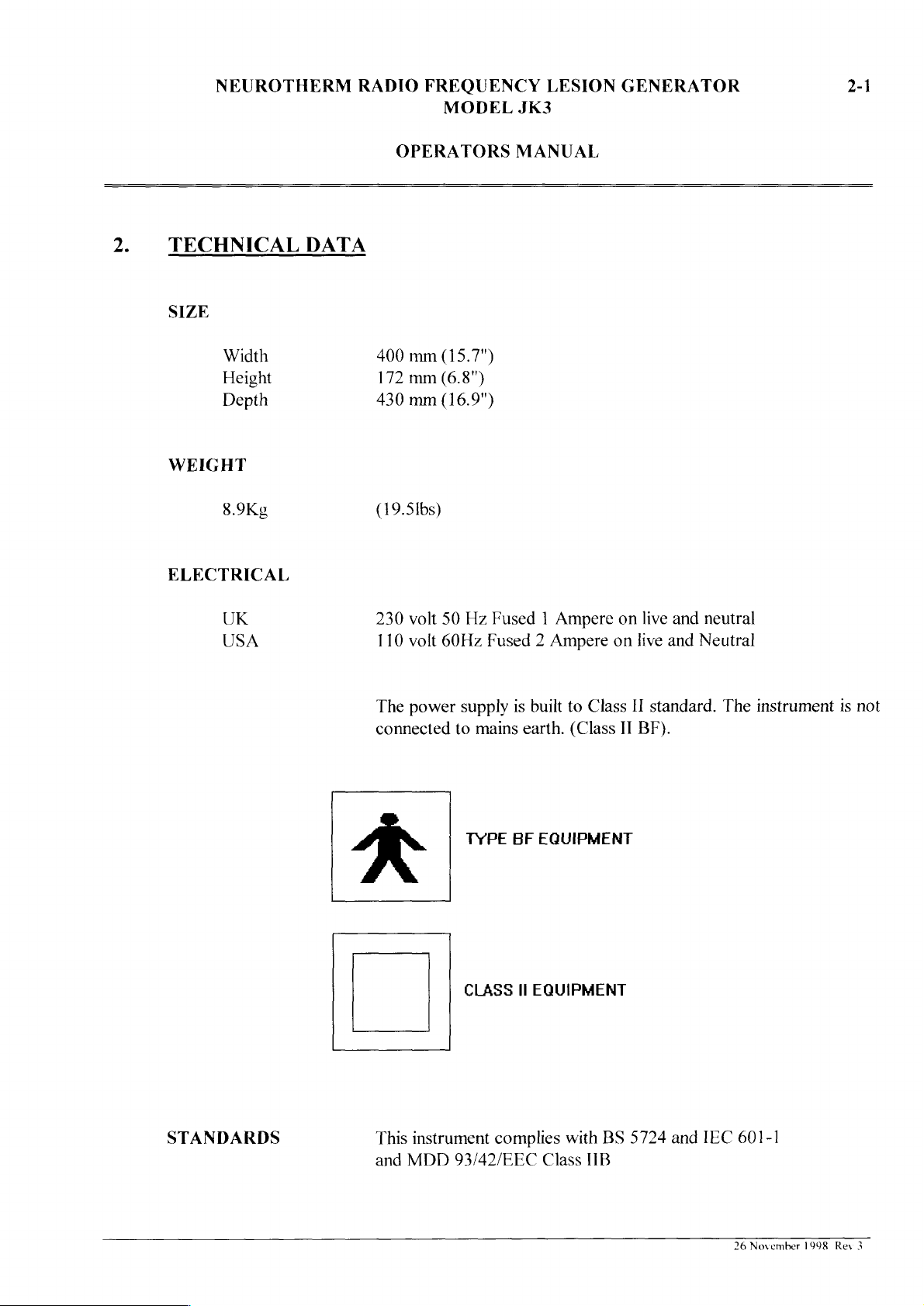
The
connected
volt
50
volt
60Hz
power
Hz
Fused 1 Ampere
Fused 2 Ampere
supply
to
TYPE
CLASS
is
mains
BF
II
built
to
earth.
(Class
EQUIPMENT
EQUIPMENT
on
on
Class
II
live
and
live
and
II
standard.
BF).
neutral
Neutral
The
instrument
is
not
STANDARDS
This
instrument
and
MDD
complies
93/42/EEC
with
Class
BS
IIB
5724
and
IEC
601-1
26
November
1998
Rey
3
NEUROTHERM
RADIO
FREQUENCY
MODEL
JK3
LESION
GENERATOR
2-2
OPERATORS
MANUAL
IMPEDANCE
Measuring
Digital
Accuracy
Digital
frequency
Display
Display
Reading
53
KHz
0-2000
+
20%
Digital
display
approx
Ohms
(in 1 ohm
reads
biological
steps)
impedance
Self
Test
500
+5%
Ohm
STIMULATOR
Voltage
Amplitude
Continuously
voltage
in
0.01
supplied
Volt
steps.
variable
between 0 - 2 volts.
is
displayed
on
the
Digital
The
Meter
Accuracy
Pulse
Rates
Pulse
Width
Waveform
Lamp
Test
Indicator
Facility
+
5%
of
reading
3
or
100
ImSec
Biphasic
Green
pulses.
LED
continuous
Indicator
When
will
only
Needle
indicate
Hz
(pulses
Negative
flashes
at a pulse
lights
is
touched
that
output
per
at
pulse
rate
when
second)
pulse
rate
of
100
output
on
Test
is
present
leading
of 3 Hz
Hz.
is
present
Block
and
is
sounder
26
November
1998
Rev
3

NEUROTHERM
RADIO
FREQUENCY
MODEL
JK3
LESION
GENERATOR
2-3
OPERATORS
RF
LESION
RF
Power
Pulsed
Voltmeter
Self
POWER
frequency
Output
RF
Power
Test
(Continuous
RF
MANUAL
Power
300
or
kHz
Continuously
Watts
I
watt)
The
set
every
500
0 - 40
Into
200
Pulsed
(+10%)
into
200
Power
mSec
RF
Volts
Ohm
RF
Power)
sine
wave
variable.
Maximum
Ohms.
Output
dummy
load
power
(Cordotomy
is
applied
resistance
output
socket
for
20mSec
built
into
8
0-
machine
LESION
Lamp
Indicators
TIMER
Range
Time
Indicator
Audible
Indicator
Amber
and
Timer
120
power
lesion
Switch
resets
Clock
LED
power
counts
or
180
is
turned
power
to
the
Indicates
lesioning.
tone
sounds
needle.
Power
point
A
one
Tone
to
for
the
second
flashes
is
active.
down
seconds.
off.
is
established.
any
position
time
to
its
amount
At
the
and
can
be
the
OFF
next
"tick"
when
from
Timer
Timer
set
point.
end
of
power
stopped
position.
lesion.
indicates
this
facility
preset
stops
can
Turning
other
of
time
the
preset
is
removed
by
Timer
the
is
times
when
be
restarted
the
than
"LESION"
remaining
period
turning
resets
clock
in
circuit
of
60, 90,
lesion
when
Function
for
alarm
from
the
is
the
Lesion
to
set
running.
.
TEMPERATURE
Meter
Range
MONITOR
30°C
to
100°C
26
November
1998
Rev
3
NEUROTHERM
RADIO
FREQUENCY
MODEL
JK3
LESION
GENERATOR
2-4
OPERATORS
MANUAL
PROBES
No
Use
only
NeuroTherm
Thermocouple
LAMP INDICATOR
SAFETY
FEATURES
Safety
Cut
Out
probes
individual
LED
shows
or
Red
with
Lesion
Power
temperature
temperature
Power
will
temperature
the
set
limit.
Green
thermocouple
reaches
switch,
automatically
of
adjustment
with
is
the
tip
necessary
thermocouple
disconnected
automatically
set
limit
as
determined
70°C,
80°C,
increase
of
the
again
probe
connected
or
reduced
90°C.
once
drops
faulty.
if
by
Lesion
the
below
Safety
Interlock
On
Pulsed
Lesion
Power
Power
Control
prevents
power.
control
out.
1
metre.
If
is
This
RF
temperature
cannot
is
first
any
accidental
the
lesion
on, a high
warning
be
set
power
pitched
tone
is
limit
is
42°C.
delivered
to
the
OFF
unless
position,
application
is
selected
warning
tone
approximately
of
and
the
the
power
is
given
80dB
RF
this
RF
at
26
November
1998
Rev
3
NEUROTHERM
RADIO
FREQUENCY
MODEL
JK3
LESION
GENERATOR
2-5
OPERATORS
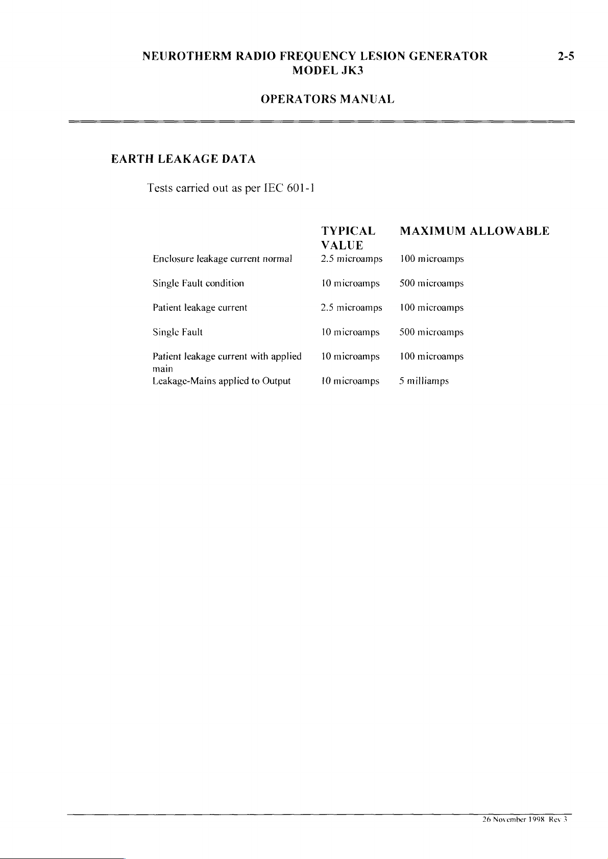
EARTH
LEAKAGE
Tests
carried
out
DATA
as
per
IEC
601-1
MANUAL
TYPICAL
MAXIMUM
ALLOWABLE
VALUE
Enclosure
Single
Patient
Single
Patient
main
Leakage-Mains
leakage
Fault
condition
leakage
Fault
leakage
current
current
current
applied
normal
with
to
Output
applied
2.5
microamps
{0
microamps
2.5
microamps
10
microamps
10
microamps
10
microamps
100
microamps
500
microamps
100
microamps
S00
microamps
100
microamps
5
milliamps
26
November
1998
Rev
3
 Loading...