

0
(14.11
.2012
)
Technical Manual
Neuro-Audio-Screen
Neuro-Audio-Screen/OAE
Portable All-in-One ABR, DPOAE&TEOAE
Hearing Screening Systems
TM057.02.002.00

Neurosoft Ltd. © 2013
5, Voronin str., Ivanovo, 153032, Russia
P.O. Box 10, Ivanovo, 153000, Russia
Phone: +7 (4932) 24-04-34 Fax: +7 (4932) 24-04-35
E-mail: com@neurosoft.ru Internet: www.neurosoft.ru

Table of Content
Introduction............................................................................................................... 5
List of Abbreviations ................................................................................................ 6
1. Important Safety Instructions ........................................................................... 7
2. Description and Operation................................................................................ 9
2.1. Neuro-Audio-Screen Function....................................................................... 9
2.1.1. Otoacoustic Emission and its Recording............................................... 9
2.1.2. Auditory Brainstem Response and Its Recording................................ 10
2.2. Main Specifications..................................................................................... 11
2.3. Arrangement and Operation........................................................................ 14
3. Description and Delivery Set .......................................................................... 16
4. Mounting and Setting...................................................................................... 19
4.1. Unpacking and Check of Delivery Set......................................................... 19
4.2. Room Selection and Placement.................................................................. 19
4.3. Requirements to the Personnel Conducting Mounting and Setting.............. 19
4.4. Getting Started............................................................................................ 20
5. Functioning...................................................................................................... 21
5.1. Control and Indication Tools ....................................................................... 21
5.1.1. Control Buttons................................................................................... 21
5.1.2. Indication............................................................................................ 22
5.1.2.1. Display Means ........................................................................... 22
5.1.2.2. Displaying of Main Parameters .................................................. 22
5.1.3. Connectors......................................................................................... 24
5.2. Turning on .................................................................................................. 25
5.3. Rechargeable Battery Charge..................................................................... 25
5.4. Entering of Personal Data of New Patient, Selection of Patient from
Database, Removal of Patient Data............................................................ 29
5.5. Patient Preparation for OAE Test................................................................ 31
5.6. TEOAE Test ............................................................................................... 34
5.7. DPOAE Test............................................................................................... 37
5.8. Patient Preparation for ABR Test................................................................ 40
5.9. ABR Test .................................................................................................... 41
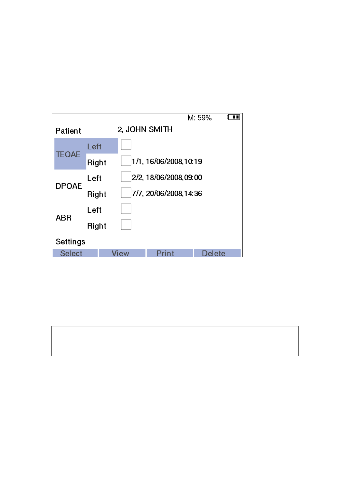
5.10. Review, Printing and Removal of Results ................................................. 44
5.10.1. Review and Printing of Test Results................................................. 45
5.10.2. Removal of Test Results................................................................... 48
5.10.3. TEOAE Report Description............................................................... 49
5.10.4. DPOAE Report Description .............................................................. 50
5.10.5. ABR Report Description.................................................................... 52
6. Settings ............................................................................................................ 53
6.1. General Settings......................................................................................... 55
6.2. TEOAE Settings.......................................................................................... 56
6.3. DPOAE Settings ......................................................................................... 57
6.4. ABR Settings .............................................................................................. 59
6.5. System Settings.......................................................................................... 60
7. Data Exchange with Computer ....................................................................... 65
7.1. Screening System Connection to Computer ............................................... 65
7.2. Operation with Neuro-Audio-Screen Manager Software.............................. 69
7.2.1. Receiving of Patient List and Exams .................................................. 72
7.2.2. Operation with Saved Exams ............................................................. 74
3

7.2.3. Exam Review and Print ...................................................................... 75
7.2.4. Operation with Patients List................................................................ 75
7.2.5. Service Functions............................................................................... 78
7.2.6. Firmware Updating ............................................................................. 79
8. Troubleshooting .............................................................................................. 82
9. Technical Servicing......................................................................................... 84
9.1. General Requirements................................................................................ 84
9.2. Maintenance Works.................................................................................... 84
9.3. Cleaning and Desinfection.......................................................................... 84
9.4. Device Functioning Check Using Test Cavity.............................................. 85
9.5. OAE Probe Check ...................................................................................... 86
9.6. Conservation .............................................................................................. 90
10. Packing and Transportation ........................................................................... 90
11. Storage Regulations........................................................................................ 91
12. Utilization of Neuro-Audio-Screen and Neuro-Audio-Screen/OAE............... 91
13. Delivery Set and Package Data....................................................................... 91
14. Acceptance Certificate.................................................................................... 92
15. Delivery Certificate .......................................................................................... 92
16. Storage Data .................................................................................................... 92
17. Warranty........................................................................................................... 93
18. Reclamation Data ............................................................................................ 94
19. Repair Data ...................................................................................................... 96
Annex 1. Electromagnetic Emission and Immunity.............................................. 97
Annex 2. Format of Neuro-Audio-Screen Exported Files................................... 101
4
Introduction
This technical manual (hereinafter referred to as “manual”) is the combined document
describing the operation and the servicing of Neuro-Audio-Screen portable all-in-one
ABR, DPOAE&TEOAE hearing screening system (hereinafter referred to as screening
systems) intended for the hearing examination of human being including the
newborns using otoacoustic emission and auditory brainstem response techniques.
The manual is the document certifying the technical parameters of the products which
are guaranteed by the manufacturer.
Read carefully this technical manual before starting to work!
You can send your responses and recommendations to the following address:
Introduction
P.O. Box 10, Ivanovo, 153000, Russia
or by e-mail:
help@neurosoft.ru.
You can find additional information on Neurosoft products in the Internet:
www.neurosoft.ru
or ask questions by phones:
+7 (4932) 24-04-37 (Service department),
+7 (4932) 24-04-34.
5

Hearing Screening Systems (Technical Manual)
List of Abbreviations
ABR – auditory brainstem response
BERA – brainstem evoked response audiometry
DPOAE – distortion product evoked otoacoustic emission
IHC – inner hair cells
LCD – liquid-crystal display
OAE – otoacoustic emission
OHC – outer hair cells
SPL – sound pressure level
TEOAE – transient evoked otoacoustic emission
6
1. Important Safety Instructions
Neuro-Audio-Screen and Neuro-Audio-Screen/OAE is designed to be used only by
those individuals trained to perform the testing for which it has been designed. No
person should attempt to use these hearing systems without the necessary
knowledge and training to understand how this equipment is to be properly utilized
and interpreted.
The hearing system probe must not be inserted into an ear without an ear
tip properly affixed.
The hearing systems do not contain high-voltage circuits inside which can represent a
danger for a human being. The hearing systems ensure the safe operation at the
correct exploitation. However, the number of precautions at the hearing systems use
exists:
Important Safety Instructions
Do not discharge the battery completely. When storing the discharged Li-ion battery
degrades fast over time.
Do not immerse the device in water or any other solutions (for example, do not
leave it near the aquarium in the presence of a child). See the device cleaning procedures in section 9 “Technical Servicing” of this manual.
Use and store the instrument indoors only. Do not expose this device or its
accessories to temperatures below 5ºC or above 40ºC, or to relative humidity of
more than 90%.
Do not drop or otherwise cause undue impact to this device. If the screening
system is dropped or otherwise damaged, return it to the manufacturer for repair
and/or calibration. Do not use the screening system if any damage is suspected.
Do not attempt to open or service the screening system. Return the device to the
manufacturer or send to the company authorized by the manufacturer for all
service. Opening the screening system case will void the warranty.
Do not operate the printer if the power supply has a damaged cord or plug.
Do not expose the printed results to sunlight or heat. Printing on thermal paper
fades with exposure to light or heat.
Photocopies of test results should be made if the records are to be kept indefinitely.
The equipment and accessories used together with the device should satisfy the
requirements stated in the present manual (table 2 and table 3 “Document code or
main specifications” column). The violation of this requirement can impact negatively the electromagnetic compatibility (result in the increase of emissions or
reduction of immunity) and also the safety and functioning of the screening system.
7
Hearing Screening Systems (Technical Manual)
Precautions at Operation with Printer and Screening System AC Power Supply
The power supply unit of Neuro-Audio-Screen and Neuro-Audio-Screen/OAE
screening systems transforms the mains voltage (220/230 V 50/60 Hz) into the direct
voltage (9 V) and is intended for the charge of the rechargeable battery built in the
device and the screening system power supply only in case the battery is discharged.
The printer power supply unit is used ONLY for the printer power supply and has the
specifications differing from the Neuro-Audio-Screen and
Neuro-Audio-Screen/OAE power supply unit. The connector of printer power supply
unit of different manufacturers can coincide with the device power supply connector. It
can cause a mistake at the power supply unit connection that is why, please, be
attentive. The use of the printer power supply unit for the supply of Neuro-Audio-
Screen and Neuro-Audio-Screen/OAE screening systems can result in the device
failure and the rechargeable battery outage.
Do not connect the printer power supply unit to Neuro-Audio-Screen and
Neuro-Audio-Screen/OAE screening systems.
It is prohibited to use the power supply of other type and manufacturer to supply the
device as it can result in the device failure or a patient’s electrical shock.
The power supply is intended for the operation from the AC power supply with
220/230 V 50/60 Hz voltage, do not insert the unit into the 380/400 V outlet.
The power supply is for indoor use only. Do not expose to water or excessive dust.
The power supply is not intended for the operation in the presence of the highly
inflammable mixture of anesthetics with an air or nitrous oxide.
Do not cover the power supply body as it may result in excessive heating.
The power supply operates when the plug is inserted into an outlet. To turn
it off, remove the plug from the outlet. The outlet must be easily accessible
and located near the printer. Should a faulty condition occur, remove the
plug from the outlet immediately.
8

2. Description and Operation
2.1. Neuro-Audio-Screen Function
The Neuro-Audio-Screen and Neuro-Audio-Screen/OAE hearing screening
systems are intended for the objective audiometry.
The devices can be applied in patient care institutions, diagnostics centers, maternity
hospitals, neuro-surgical clinics and experimental laboratories of the research
institutions for:
the study of the auditory brainstem response (ABR) (only Neuro-Audio-Screen)
(also known as brainstem evoked response audiometry (BERA));
the study of the otoacoustic emission (OAE) using TEOAE and DPOAE techniques.
Description and Operation
The screening systems allow choosing a exam type, entering a patient’s data, controlling
a exam process, results displaying and a recorded exams database. It is possible to
process and archive the exam results on the computer, print them using the printer
connected via the wireless interface.
2.1.1. Otoacoustic Emission and its Recording
What is TEOAE?
Transient evoked otoacoustic emission (TEOAE) is an acoustic signal that can be
detected in the ear canal of a person with normal outer hair cell (OHC) function,
subsequent to stimulation of the auditory system with a series of wideband clicks.
What is DPOAE?
Distortion product otoacoustic emission (DPOAE) is an acoustic signal that can be
detected in the ear canal of a person with normal outer hair cell function, subsequent
to stimulation of the auditory system with a pair of pure tones at frequencies f1 and f2.
The resulting emission of interest is the distortion product tone at the
frequency 2 f1-f2.
What Do Otoacoustic Emission Results Tell Us?
Available evidence suggests that otoacoustic emission (OAE) is generated by the
cochlea’s outer hair cells, and that the presence of OAE is an indication that the outer
hair cells are normal. Although OAE test data provide no indication of inner hair cell
(IHC) function, or of hearing ability, current research indicates that the majority of
hearing-impaired individuals will be identified by a simple OAE test. Patients who fail
to generate OAE should be re-screened and/or referred for additional audiological
testing.
9

Hearing Screening Systems (Technical Manual)
How Does Screening Systems Record TEOAE?
The Neuro-Audio-Screen and Neuro-Audio-Screen/OAE screening systems gener-
ate a series of clicks using a telephone, direct them into the ear canal, and then
average the response received by the microphone built in the probe recording OAE.
Owing to the use of the fast Fourier transform for the spectral analysis and the
bandpass filters, the devices provide an estimate of outer hair cell function over a
wide range of frequencies.
How Does Screening System Record DPOAE?
The Neuro-Audio-Screen and Neuro-Audio-Screen/OAE screening systems
generate a series of test tones using two telephones, direct them into the ear canal,
and then measure the level of the DPOAE tone generated by the cochlea by the
microphone built in the probe. By using different test frequencies, the devices provide
an estimate of outer hair cell function over a wide range of frequencies.
2.1.2. Auditory Brainstem Response and Its Recording
What is ABR?
Auditory brainstem response (ABR) is an electrical signal recorded from the
electrodes placed on the head of a patient with the normally functioning organs of
hearing including the auditory nerve and projection areas of the cerebral cortex. This
signal is the result of the auditory analyzer stimulation by the series of the auditory
pulses.
What Do ABR Test Results Tell Us?
As far as ABR is generated by the cochlea, the auditory nerve and the projection
areas of the cerebral cortex, we can safely say that the ABR presence indicates the
normal functioning of all the above mentioned auditory system parts and a patient
hears an acoustic signal directed to the ear canal.
How Does Neuro-Audio-Screen Screening System Record ABR?
The Neuro-Audio-Screen screening system generates a series of clicks using a
telephone, directs them into the ear canal, and then averages the electrical signal
received from the electrodes placed on a patient’s head. As a result ABR is obtained.
Owing to the high frequency of stimulus delivery (up to 93 Hz), the device can register
the so called steady-state potentials. These potentials differ in the high amplitude, are
easily and quickly separated, practically not influenced by the external
electromagnetic fields.
10
2.2. Main Specifications
Table 1. The Screening System Specifications
Parameters Values
ABR Technique
Recorded EP range 0.15–900 µV
Common-mode rejection not less than 100 dB
Noise level (rms) not more than 0.35 µV
Amplifiers input impedance not less than 90 MΩ
Amplifiers input capacity not more than 40 pF
Description and Operation
Differential input bias voltage, maximum permissible
Bandpass flatness in the range from 200 up to 3000 Hz
Electrode impedance range 0.5–500 kΩ
Stimulus intensity range for OAE probe 0-60 dB HL
Stimulus intensity range for TDH-39 headphones 0–100 dB HL
Stimulation frequency range 9–93 Hz
TEOAE Technique
Frequency range 400–5000 Hz
Stimulus intensity range 50–90 dB SPL
Stimulus spectrum flatness
in the frequency range 0.5–2.5 kHz
in the frequency range 0.5–5 kHz
Noise level in the frequency range 500–5000 Hz not more than 30 dB SPL
DPOAE Technique
Frequency range 0.5–12 kHz
Stimulus intensity range 30–75 dB SPL
Stimulus 3rd order intermodulation not more than -80 dB
(30030) mV
-305%
with 1 Hz step
not more than 10 dB
not more than 20 dB
General Parameters and Specifications
Automatic result analysis yes
Indication of probe setting quality yes
Number of measurements saved in a device memory:
TEOAE
DPOAE
ABR
Number of patient cards saved in device memory:
TEOAE
DPOAE
ABR
Operating time of electronic unit at rechargeable battery use from 7 up to 10* hours
LCD 3.5" with resolution not less
from 320 up to 1000
from 260 up to 700
from 1300 up to 4000
from 320 up to 500
from 260 up to 350
from 1300 up to 2000
than 640480
11
Hearing Screening Systems (Technical Manual)
Table 1. Continued
Parameters Values
Interface Bluetooth
Electronic unit power supply voltage from external power supply
unit
Safety BF
Protection class from electrical shock 1
Electronic unit dimensions
Electronic unit weight not more than 0.68 kg
Total weight not more than 2 kg
Power supply:
rechargeable battery
power supply unit:
model
supply voltage
output voltage
Note:
* depending on the operation mode of the device.
Safety and Electromagnetic Compatibility
(19510155)2 мм
Li-ion with 4400 mAh
100–240 V, 50/60 Hz, 0.8 A
9 V
capacity
PSU-9
9 V DC
Electromagnetic compatibility (EMC) is provided by IEC 60601-1-2:2007 requirements
fulfillment.
The screening systems are intended for operation in the electromagnetic environment
conditions which are specified in the appendix 1 “Electromagnetic Emission and
Immunity”.
Portable and mobile RF communication equipment may affect the system work.
The use of the equipment not listed in table 2 and table 3 of the present technical
manual may result in increased emission and system decreased immunity.
As for safety, screening systems satisfy IEC 60601-1:1988 + A1:1991 + A2:1995, IEC
60601-1-1:2000, IEC 60601-2-40:1998 standards requirements. The devices are
supplied by the external power supply unit of 9 V direct voltage or Li-ion rechargeable
battery, are related to class I and have BF type work parts according to IEC 60601-1.
All the computer equipment used together with the devices should correspond to IEC
60950-1 and CISPR 22:2006.
Interpretation of symbols on the electronic unit:
- attention: consult user and technical manuals.
- work parts of BF type according to IEC 60601-1.
12

Description and Operation
- mark of conformance to Russian standards requirements.
- mark of conformance to 93/42/EEC “Concerning Medical Devices”
directive.
- mark of conformance to 2002/96/EC “On waste electrical and electronic
equipment (WEEE)” directive.
13
Hearing Screening Systems (Technical Manual)
2.3. Arrangement and Operation
The screening system is intended for the performing of two test types: OAE and ABR.
The principle of operation at OAE performing is based on the registration of the
auditory fluctuations of the cochlea OHC with the use of the probe microphone, in
response to the auditory stimulation with the use of the telephones built in the probe.
The principle of operation at ABR performing is based on the registration of the brain
electrical response in reply to the auditory stimulation.
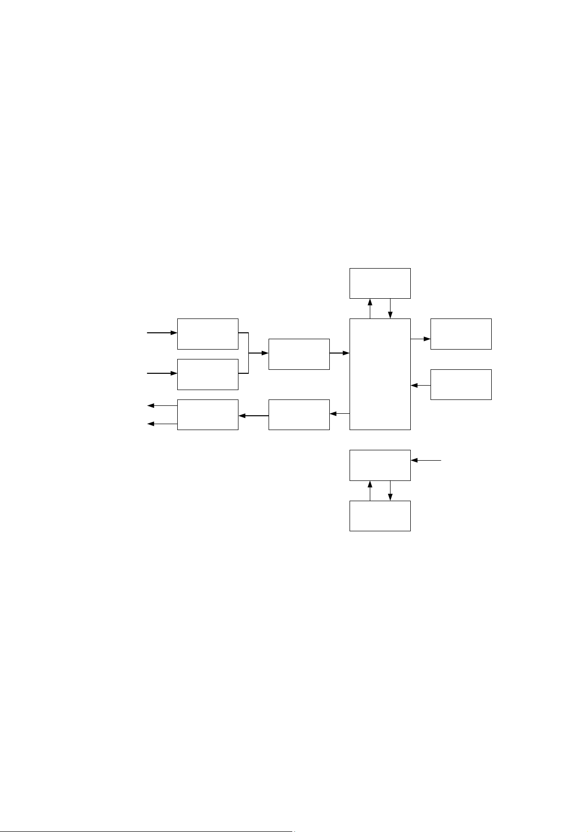
The functional scheme of Neuro-Audio-Screen screening system is presented in
the Fig. 1.
Bluetooth module
Biopotentials
electrodes
Probe microphone
Probe telephones
Headphones
Fig. 1
PU amplifier
Microphone
amplifier
Telephone
amplifier
ADC
DAC
CPM
Secondary power
supply source
Rechargeable
batteries
LCD
Keyboard
External power
supply +9 V
In the OAE test mode, the central processor module (CPM) generates the test signal
in a digital form and transfers it to the digital-to-analogue converter (DAC). The DAC
converts the signal to the analogue form and directs to the amplifier. After that, the
signal from the amplifier is transferred to the OAE probe telephones where it is
converted to the acoustic stimulus. The acoustic response of the cochlea OHC is
registered by the probe microphone and is converted to the electrical signal. Via the
microphone amplifier this signal is transferred to the analogue-to-digital converter
(ADC) input where it is converted to the digital form. The digitized response is directed
to CPM where it is processed and analyzed. The report concerning the test results is
based on the CPM analysis.
14
In the ABR test mode, the device operates in the same way. CPM generates the test
signal which is converted into the analogue form when transferring via the DAC, is
amplified by the amplifier and is directed either to the OAE probe telephones or to the

Description and Operation
headphones depending on what is used as an auditory stimulator. The brain electrical
response is recorded from the electrodes, directed to the biopotentials amplifier input
and then amplified. After that, it is transferred to the ADC, converted to the digital form
and directed to CPM. CPM processes and analyzes the received response and gen-
erates the report concerning the test results.
Except the above-mentioned functions, CPM controls completely the device
operation, keeps the settings and test results, displays the test procedure, test results,
service information using the LCD display. To transfer the results to the computer or
thermal printer and also to download the list of patients from the computer, CPM uses
Bluetooth module which provides the implementation of the Bluetooth wireless
interface. CPM is controlled by a user from a keyboard.
To provide the required supplying voltages for all the scheme units, the secondary
power supply source is provided. It can operate both from the built-in rechargeable
battery and external power supply. In the last case it provides the charge of the built-in
rechargeable battery.
15
Hearing Screening Systems (Technical Manual)
3. Description and Delivery Set
Neuro-Audio-Screen and Neuro-Audio-Screen/AOE screening systems are pocket
devices developed for the performing of the objective test of the auditory function. It
consists of the portable unit to which the OAE probe and electrodes for ABR recording
can be connected, the software for the data downloading from the device to the PC,
wireless thermal printer with Bluetooth interface for the printing of the tests results (is
not included in the base delivery set), set of ear tips and other accessories.
The delivery sets of Neuro-Audio-Screen and Neuro-Audio-Screen/AOE screening
systems are presented in the Table 2 and Table 3 (1 and 2 columns correspondingly).
Table 2. Base Delivery Set
Name
Neuro-Audio-Screen electronic unit
Neuro-Audio-Screen/OAE electronic
unit
Power supply unit PSU-9 NSFT 057201.009 1 1
Power cord SCZ-1 (1.5 m.) 1 1
Bluetooth adapter1) 100 m, class 1, V.2.1, CSR chipset 4 4
Accessories for EP and OAE Studies
Cable for reusable electrodes
connection
OAE probe 2) NSFT 006355.003-00
Set of OAE probe tips ER10D-RPT
Set of ear tips (pediatric) NSFT 007998.001 SP 1 1
Cable for disposable electrode
connection:
Alligator clip – touch-proof
(green, red or black)
Document code or main
specifications
NSFT 057201.015 1 –
NSFT 057201.016 – 1
NSFT 057103.003-05 1 –
OAE-02-2
NSFT 006355.003-01
OAE-02-2
NSFT 006221.001
NSFT 990103.027-02.05
NSFT 990103.027-03.05
NSFT 990103.027-04.05
Number, pcs.
1 2
1 1
1 1
1
1
1
–
Disposable surface electrode (100
pcs.) 1)
Test cavity NSFT 006201.013 1 1
Screw driver №1 GOST 17199 1 1
Dental floss Regular Oral-B (pack –
50 pcs)
Probe tip extractor NSFT 006206.016 1 1
16
F3081, F3001 3
pack.
Oral-B, Ireland
–
1 1
Table 2. Continued
Description and Delivery Set
Name
Document code or
main specifications
Number, pcs.
1 2
Operational Documentation
Neuro-Audio-Screen,
Neuro-Audio-Screen/OAE technical manual
Neuro-Audio-Screen, Neuro-Audio-
Screen/OAE calibration guidelines
OAE probe guidelines
Video manual on CD Version not lower than
TM057.02.002.000 1 1
CG057.01.001.000 1 1
GL032.03.001.000 1 1
001
1 1
Software
Neuro-Audio-Screen manager software
without additional
modules
1 1
Package
Transportation bag - 1 1
Note:
1)
The accessories and consumables of analogous types can be applied, but their use should
be permitted in the country.
2)
OAE probe NSFT 006355.003-01 is supplied with probe tip NSFT 006221.001, and OAE
probe NSFT 006355.003-00 is supplied with probe tip ER10D-RPT.
Table 3. Additional Equipment, Accessories and Software
Name Document code or main specifications
Number, pcs.
1 2
Accessories for EP and OAE Studies
Auditory stimulator
(headphones)
Insert earphones for
NSFT 032305.005 (TDH-39)
NSFT 015305.001 (TA-01)
ER3-10 1 –
1 –
audiometry
Set of disposable foam ear tips ER3-14A, ER3-14B, ER3-14D2, ER3-14C,
1 –
ER3-14E2
Adapter for earphones for
NSFT 032103.004 1 –
audiometry
Cup EP electrode with cable
(green, red, black) 1)
NSFT 990106.028-02.05 (F8909Z)
NSFT 990106.027-02.05 (EEP)
NSFT 990106.028-03.05 (F8909Z)
NSFT 990106.027-03.05 (EEP)
1 –
1 –
NSFT 990106.028-04.05 (F8909Z)
NSFT 990106.027-04.05 (EEP)
1 –
17
Hearing Screening Systems (Technical Manual)
Table 3. Continued
Name
Document code
or main specifications
Number, pcs.
1 2
Consumables
Electrode adhesive paste
Electrode abrasive paste
for skin preparation 1)
1)
TC 9398-011-34616468-2002
Unipasta, 120 g
1
Everi, Italy, 160 g. 1
Software
Neuro-Audio.NET
version not less than 1.0.6.0 1 1
software
Computer and Electronic Equipment 2)
System unit3) TC 4013-003-13218158-2011
1 1
“Functional”
“Elegant”
“Elite”
Notebook PC Minimal requirements
1 1
according to recommendations
stated in section 7.2
Monitor LCD 19’’ 1 1
Printer for personal
Laser or jet 1 1
computer
–
–
Printer for electronic unit CUSTOM S’Print BT
1 1
Citizen CMP10 2 Bluetooth
Note:
1)
The accessories and consumables of analogous types can be applied, but their use should
be permitted in the country.
2)
All the computer equipment should conform to IEC 60950-1 and CISPR 22 for B class.
3)
The supply of other computer with the same or better specifications is allowed (see section
7.2).
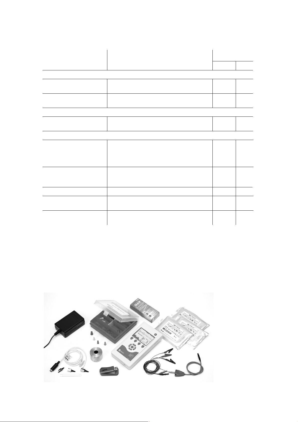
The appearance of Neuro-Audio-Screen screening system with all the accessories
included in the base delivery set is shown in the Fig. 2.
Fig. 2. The appearance of Neuro-Audio-Screen screening system and accessories.
18
4. Mounting and Setting
4.1. Unpacking and Check of Delivery Set
If the box with screening system was under conditions of the excessive moisture or
low temperature which differs sharply from working conditions, it is necessary to place
it in the room and leave for 24 hours in normal conditions.
Unpack the box, extract the screening system and the components. The delivery set
should correspond to the report concerning the device packing.
The computer equipment packed in the separate boxes should be opened according
to user and technical manuals for these products.
Check screening system and components to make sure that there are no external
damages.
Mounting and Setting
4.2. Room Selection and Placement
The Neuro-Audio-Screen and Neuro-Audio-Screen/OAE screening systems are
portable devices that is why its exploitation is allowed in any rooms of patient care
institutions where the temperature and the humidity of the environment corresponds to
the conditions described in the device specifications. Also it is allowed to use the
device for the exam performing at patient’s place.
The room for OAE studies performing should be free from the noise
sources such as electrical motors, powerful ventilators, electric kettles,
audio equipment, aquarian compressors, etc.
4.3. Requirements to the Personnel Conducting
Mounting and Setting
There are no special requirements to the personnel conducting screening system
mounting and setting.
The replacement of the rechargeable battery must be performed in the service centers
of Neurosoft Company.
19
Hearing Screening Systems (Technical Manual)
4.4. Getting Started
The offered sequence of operations will allow you to speed up the use of
Neuro-Audio-Screen screening system for OAE recording. The operating order of
ABR test performing is described in section 5.8 “Patient Preparation for ABR Test”
and section 5.9 “ABR Test”. The first four steps are fulfilled in any case regardless of
the used technique.
First of all perform the otoscopic study prior to testing. Read carefully this technical
manual before you start to examine the patients.
Step 1. Connect the power supply unit to charge the battery. The battery is charged
for 3-4 hours (see section 5.3 “Rechargeable Battery Charge”).
Step 2. Connect the OAE probe to the screening system. Place the ear tip as far
down as possible on the OAE probe tip.
Step 3. Switch on Neuro-Audio-Screen by pressing on/off button for 2 seconds.
Step 4. After screening system loading, set the printer type and address if you have
wireless thermal printer. Enter the OAE probe sensitivity, date and time. Set the report
type. The detailed procedure is described in section 6.5 “System Settings”.
Step 5. Insert the ear tip deeply into the patient’s ear canal to obtain a seal. The order
of OAE probe insertion into the ear canal is described in section 5.5 “Patient Preparation for OAE Test”. Choose the technique and the tested ear with the use of “up/down”
buttons and “Select” key.
Step 6. First, Neuro-Audio-Screen checks the quality of OAE probe setting, performs
calibration automatically and then fulfills OAE recording. At high noise level the noise
level indicator highlights red. This is normal and it takes place quite often. Anyway the
study can be performed if the indicator does not glow red constantly, however it
impacts the final result of the recording. Once the test is finished, the test result is
displayed on the screen (PASS/REFER).
Step 7. After the test finishing, you can save the results in the screening system
memory by pressing “Close” button and answering “Yes” to the question “Save
exam?”. If you have printer, you can print the results. Switch on the printer by pressing
the round button on top. Press “Print” button on the screening system. The results of
the current exam will be printed.
20
5. Functioning
3
2 1
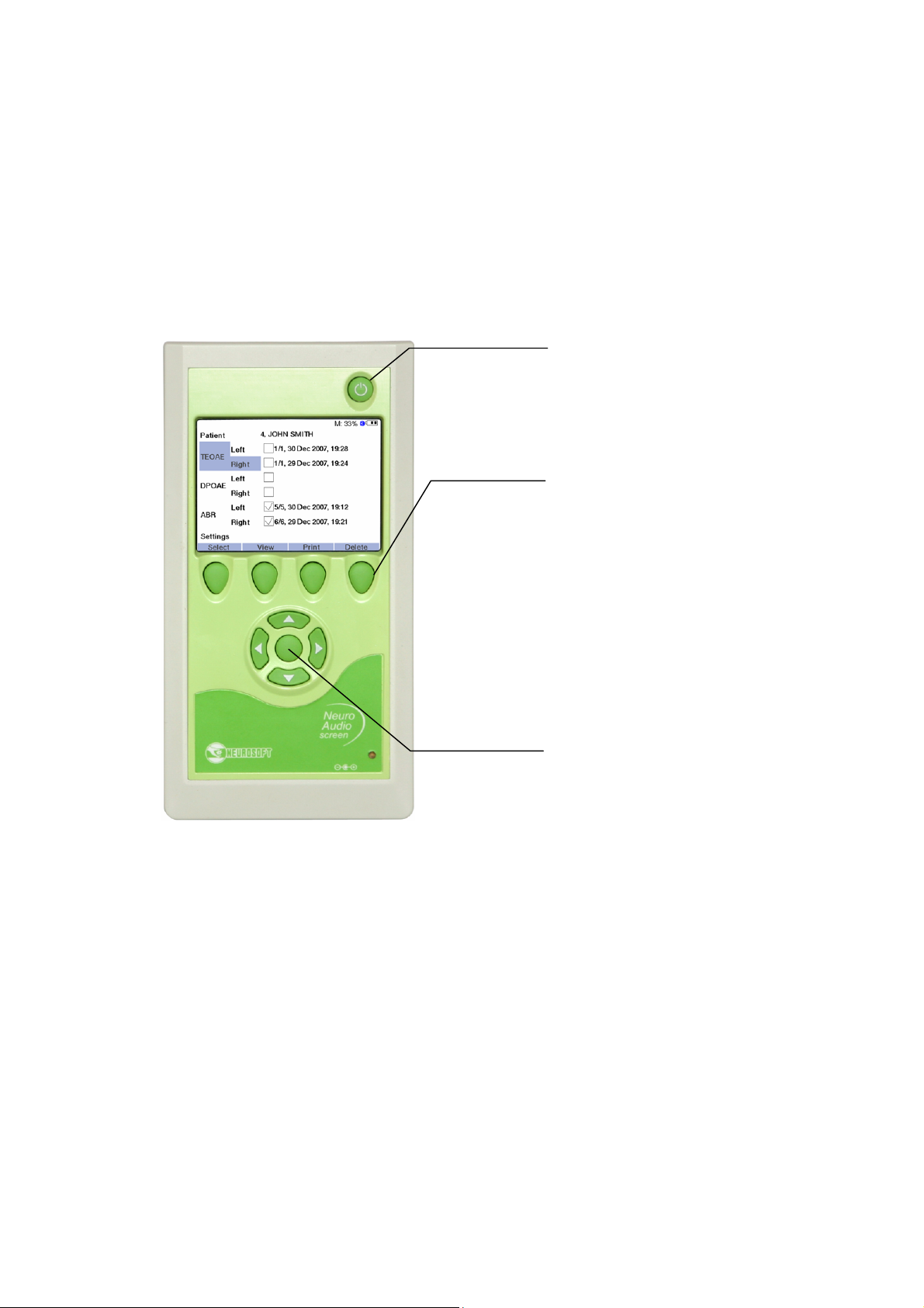
5.1. Control and Indication Tools
5.1.1. Control Buttons
The front panel of Neuro-Audio-Screen and Neuro-Audio-Screen/OAE screening
systems contains the following control buttons (Fig. 3).
Functioning
Fig. 3. The front panel of Neuro-Audio-Screen and Neuro-Audio-Screen/OAE screening system (1).
1. On/Off button.
2. Four multifunctional buttons. They are used for the selection of the menu items,
the entering of the personal patient’s data, the printing of the results, the
performing of the tests, the saving of the exams, the reviewing of the test results,
etc. The function of each button varies depending on the current operation mode
(the exam, the review, etc.) and is displayed in the text line straight above the
button. Further in the text the denotation of these buttons indicated in the text line
will be used in this manual, for example: Press the “Close” button. It means that it
is necessary to press the multifunctional button above which at present moment
the text “Close” is displayed. The text line will be further named “active menu”.
3. The arrow buttons are for the shifting right-left, up-down and the selection button
in the center. The buttons are intended for the moving over the menu items and
21
Hearing Screening Systems (Technical Manual)
2
1
choosing the menu item, the text typing, the settings change. The denotations
“left”, “right”, “up”, “down”, “Select” will be used further in the text.
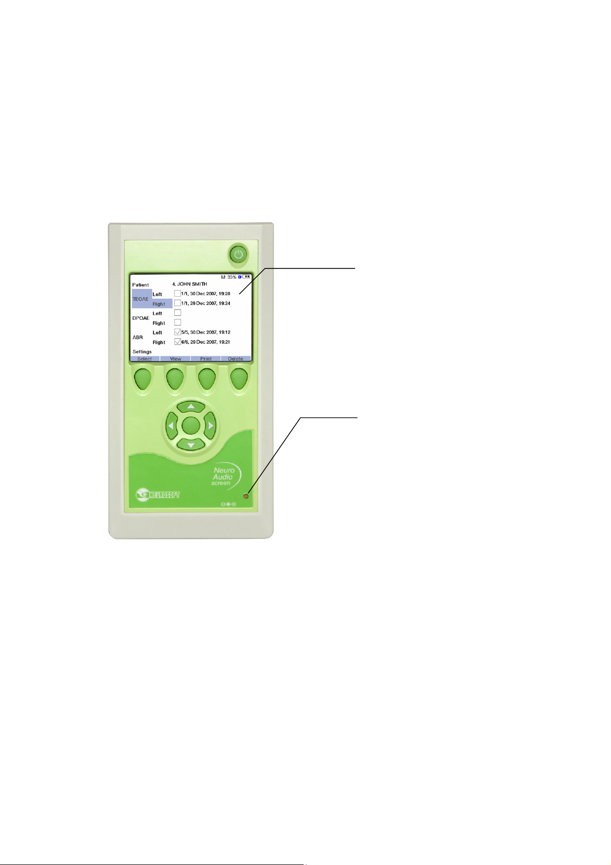
5.1.2. Indication
5.1.2.1. Display Means
The front panel of Neuro-Audio-Screen and Neuro-Audio-Screen/OAE screening
systems contains the following display means (Fig. 4).
22
Fig. 4. The front panel of Neuro-Audio-Screen and Neuro-Audio-Screen/OAE screening systems (2).
1. TFT LCD display. It is used for the displaying of the menu, the settings, the exam
procedure and results, the additional information (battery condition, free space,
Bluetooth mode (on/off) and the text line (the function of multifunctional buttons)).
2. The indicator of the rechargeable battery charge. The indicator does not light up if
the power supply unit is not connected to the device, glows green in case the
battery is completely charged and glows yellow if the charging is taking place.
5.1.2.2. Displaying of Main Parameters
The indicator of the rechargeable battery charge operates in one of four modes:
1. The indicator is damped. It means that the device is either switched off or
operates from the built-in rechargeable battery.
2. The indicator glows green. This mode is activated when the device operates from
2 3 4
1
the power supply unit after the rechargeable battery charge termination.
3. The indicator glows yellow. It means that the rechargeable battery is being
charged. It is displayed when the device is supplied from the power supply unit.
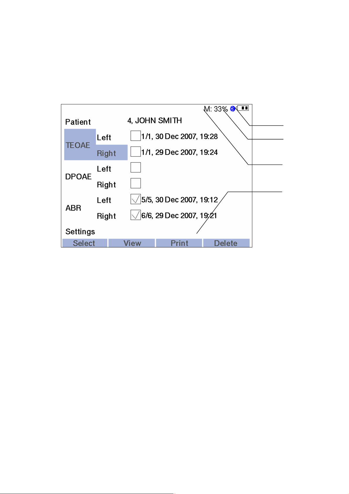
The following message information is displayed on the LCD screen (Fig. 5).
Functioning
Fig. 5. The displaying of the message information.
1. The condition of the rechargeable battery as a sign with three segments. At
the completely charged rechargeable battery all the three segments are
displayed. During the battery discharge the number of the displayed segments
lessens.
2. The icon of Bluetooth technology. It means that the connection via the wireless
channel is activated at the present moment.
3. The letter “M” and the numerical value. It corresponds to the free space in the
percents left on the disk for the storage of the exam data.
4. The active menu line. The function of each of the four multifunctional buttons at
the present moment of time is displayed here.
The main part of LCD screen displays the information concerning the current exam or
menu items.
23
Hearing Screening Systems (Technical Manual)
1 2 3
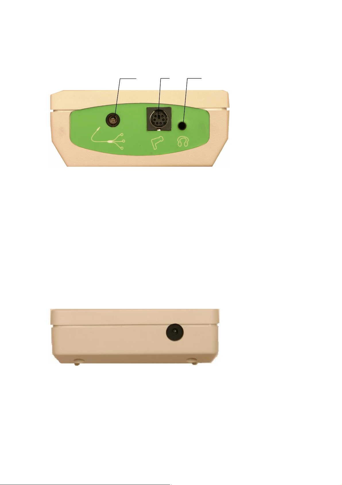
5.1.3. Connectors
The top panel of Neuro-Audio-Screen and Neuro-Audio-Screen/OAE screening
systems contains the following connecting jacks (Fig. 6).
Fig. 6. The top panel of Neuro-Audio-Screen screening system.
1. The connector for cable for electrodes connection for Neuro-Audio-Screen (cup
EP electrodes or disposable EP electrodes are attached to this cable) (is absent
in Neuro-Audio-Screen/OAE)
2. The connector for OAE probe.
3. The connector for the telephones attachment (is absent in
Neuro-Audio-Screen/OAE). The telephones are not included in the base
delivery set and are bought separately. It is allowed to connect the telephones of
different manufacturers. The resistance of the telephones should be not less than
10 Ω.
The bottom panel of Neuro-Audio-Screen and Neuro-Audio-Screen/OAE screening
systems contains the connector for the power supply unit (Fig. 7).
Fig. 7. The bottom panel of Neuro-Audio-Screen and Neuro-Audio-Screen/OAE screening systems.
24
5.2. Turning on
To turn on Neuro-Audio-Screen and Neuro-Audio-Screen/OAE screening systems
press and hold the device on/off button for about 2 seconds (Fig. 3). If the rechargeable battery has enough capacity, than the screen highlight will switch on in 3 seconds
and the message information (the built-in software downloads into the device) will appear on the screen. After that, the main menu window will display on the screen
(Fig. 8).
Functioning
Fig. 8. The main menu window.
If the device is not switched on at the pressing and holding of the on/off button or is
switched off at the buttons release, see the section “Troubleshooting”.
If the rechargeable battery is absent, it is necessary to connect the power supply unit
included in the delivery set.
It is prohibited to use the power supply unit of other type and manufacturer.
It can lead to the device failure or patient’s electrical shock.
If the device is switched on for the first time, it is necessary to set the date and time
(see the section 6 “Settings”). You should also set the printer address and type if you
want to use the wireless thermal printer. It is necessary to enter the probe sensitivity
(see section 6.5 “System Settings”).
5.3. Rechargeable Battery Charge
The rechargeable battery can be charged in two modes:
1. The device is switched on and used for the exams.
25
Hearing Screening Systems (Technical Manual)
2. The device is switched off.
It is allowed to charge the battery in both modes. At that, if the device is switched on
and is used for the exam performing, the charge process does not impact
the measurement accuracy and TEOAE and DPOAE test results.
During the ABR test it is recommended to disconnect the power supply unit
from the device to get more reliable test results.
The charge of the battery is required if during the device operation the state of charge
is indicated as an empty one. To do this, connect the power supply unit to the connector for the battery charge (see the section 5.1 “Control and Indication Tools”).
The connection of the power supply unit is allowed in both above-mentioned modes
(the device is switched on and off). After the connection the indicator on the front
panel (see the section 5.1 “Control and Indication Tools”) should glow yellow which
means the start of the charge procedure. The battery charge procedure lasts for about
3-4 hours. The light increase of the temperature of the battery compartment cover and
the whole rear panel is admissible during the charge process. If the device is switched
on, the sign with the three segments will display on the screen during the charge
process. It does not mean the charge termination, it indicates that the power supply
unit is being connected to the device.
The end of the charge process is defined only by the indicator located on
the front panel.
After the charge process finishing, the indicator on the front device panel should glow
green, what means the successful completion of the charge process. After that, one
can disconnect the power supply unit and operate autonomously (for more
convenience). It is also allowed to use the device with the connected power supply
unit after the finishing of the charge process to prolong the service life of the battery.
If the battery charge is completed successfully (the green indicator highlighted), and
you operate on the device supplied from the power supply unit, than in some time
(several hours) of the continuous work the indicator will glow yellow. It means that
the rechargeable battery is discharged during the operation (at the device supply from
the power supply unit, the battery also discharges but much more slowly; it is called
self-discharge) and the process of the charger switched to the mode of the battery
“subcharge”. In this case the battery will charge automatically, at that the indicator will
glow yellow and after the end of the “subcharge” process it will highlight green again.
During the charge process the battery temperature is controlled. If the specified level
is exceeded, the charge cycle ends. When the battery temperature falls up to the
normal level, the charge cycle renews. It allows charging the battery without close attention of the personnel and leaving the device with the power supply unit connected
to the mains for a night. However it is not recommended to leave the device being
plugged to the mains for longer periods.
26

Before starting to use the rechargeable battery, it is necessary to charge it
completely.
Battery Capacity at the Delivery
The supplied rechargeable battery is delivered in a partially discharged state, as it
takes considerable time from the complete charge at the manufacturer’s plant.
The spontaneous discharge of the rechargeable battery at the room temperature
achieves 5% per month. It means that the battery can half discharge in 9-12 months
after its complete charge.
Life Time of Rechargeable Battery
The life time of battery is defined by the number of complete “charge-discharge”
cycles. In real use conditions the number of cycles varies from 500 to 1000 depending
on the discharge depth, at that the battery capacity decreases to 60-80% from the
nominal value. The number of cycles corresponds to 2-4 years of real operation (in
average, 5-6 “charge-discharge” cycles per week).
Functioning
The life time of battery is not indicated. Usually the storage life before the operation
start is 2 years.
Important Note Concerning the Correct Use and Charge of Li-Ion Battery
The battery is exposed to wear because of its construction. The life time of the battery
depends also on the correct technical servicing. The charge and the discharge are
the most important wear-out factors.
As far as the Li-ion battery have no “memory effect”, it is allowed to charge/discharge
the battery at any charge level. Though once every several months it is recommended
to discharge the device completely, i.e. wait for the device switching off and then
charge it completely.
Often complete discharge of the battery is not recommended. If the battery is
discharged completely, charge it as soon as possible.
The overcharge is even more harmful for the Li-ion battery than the over-discharge.
The controller limits the maximal charge level but there is one peculiarity. It is well
known that the battery capacity depends on the temperature. Thus, for example, we
charged the battery at the room temperature and obtained 100% charge, the battery
charge level may decrease to 80% and more when going out to the frosty weather and
device cooling down. The reverse situation may also happen. The battery charged
100% at room temperature may warm to 105% what is rather bad for it. Such situations
may occur if the device operates with the connected power supply unit during the longterm period of time. During the operation the temperature of the device and also
the battery increase and as far as the charge is complete, the over-charge takes place.
That is why if you intend to work with the mains supply, disconnect the device from the
27

Hearing Screening Systems (Technical Manual)
power supply unit first, work with the device for some time. As soon as the device starts
working in an “operating conditions”, connect the power supply unit.
Also it is important to observe the temperature conditions during the battery discharge
and especially charge. The optimal ambient temperature during the charge is about 15–
25ºC. Do not allow the device operation if the temperature exceeds 35ºC or goes
below 0ºC.
The battery may also self-discharge. This process depends on the environment
temperature. If the temperature is high, the battery discharges with higher speed.
The high humidity, high temperature and long-term storage also contribute to selfdischarging.
Storage of Li-ion Battery
Li-ion battery should be stored charged. If Li-ion battery is kept with 2.75 V voltage
and lower for three months or more, the battery capacity will be lowered greatly.
Besides the corrosion of the elements may occur. The recharge of the Li-ion battery is
not allowed if the voltage at the element pins dropped below the critical level. This is a
safety requirement as far as the chemical structure of the completely discharged
element changes and the recharging may be harmful. The best results may be
achieved if you store half-charged battery.
Replacement and Utilization of Li-ion Battery
In some years of operation the replacement of Li-ion battery may be required.
The replacement is carried out in the specialized service centers of Neurosoft
Company. The used Li-ion battery must be utilized according to the accepted norms.
The battery contains the poisonous hydride of heavy metals and should be utilized in
special places.
28
5.4. Entering of Personal Data of New Patient,
Selection of Patient from Database, Removal of
Patient Data
Neuro-Audio-Screen and Neuro-Audion-Screen/OAE screening systems allow to
enter the data of new patients to the memory (maximum 100), save the personal data
and patient’s exam results, remove the personal data and the results of patients’
exams.
The device memory is limited that is why it is necessary to remove the
unnecessary personal data and results of patients’ exams to free the space
for the new exam data.
The data in the device are saved even at the power supply blackout.
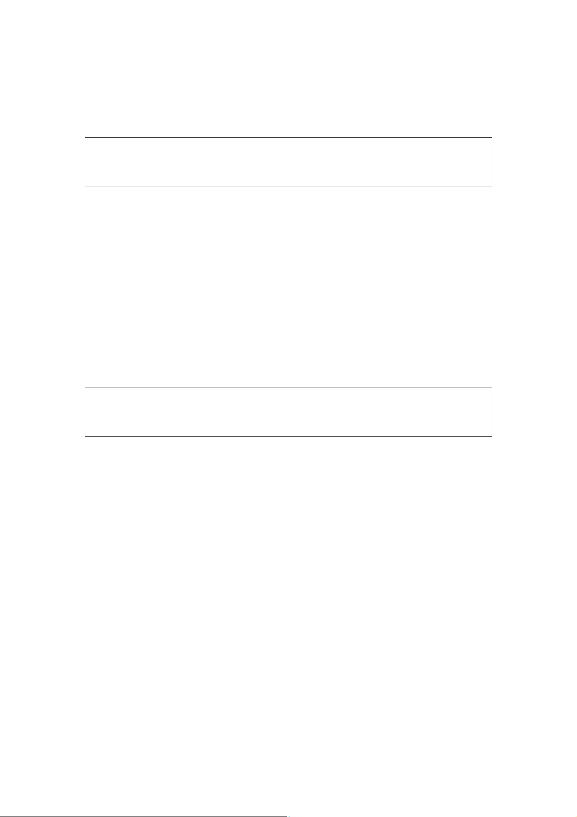
To start the exam of a new patient (a new patient is considered the one whose personal data are not saved in the device memory), it is necessary to enter her/his data
to the device. To do this, select the item “Patient” of the main menu (Fig. 8) using the
arrow buttons and press the “New” button. After that, the new window (Fig. 9) with the
listed patient’s data entered in the device memory will appear. It is necessary to point
out that it is not required to enter all the patient’s data (name, sex, date of birth, comments) to the device. You can leave all the edit lines empty, than a patient’s identification will be performed by the automatically generated patient’s number.
Functioning
If you want to edit a patient’s data saved already in the device memory, choose the
“Patient” item of the main menu and press the “Select” button. The same window as
for a new patient will be opened.
Fig. 9. The window of a new patent data entering.
29
Hearing Screening Systems (Technical Manual)
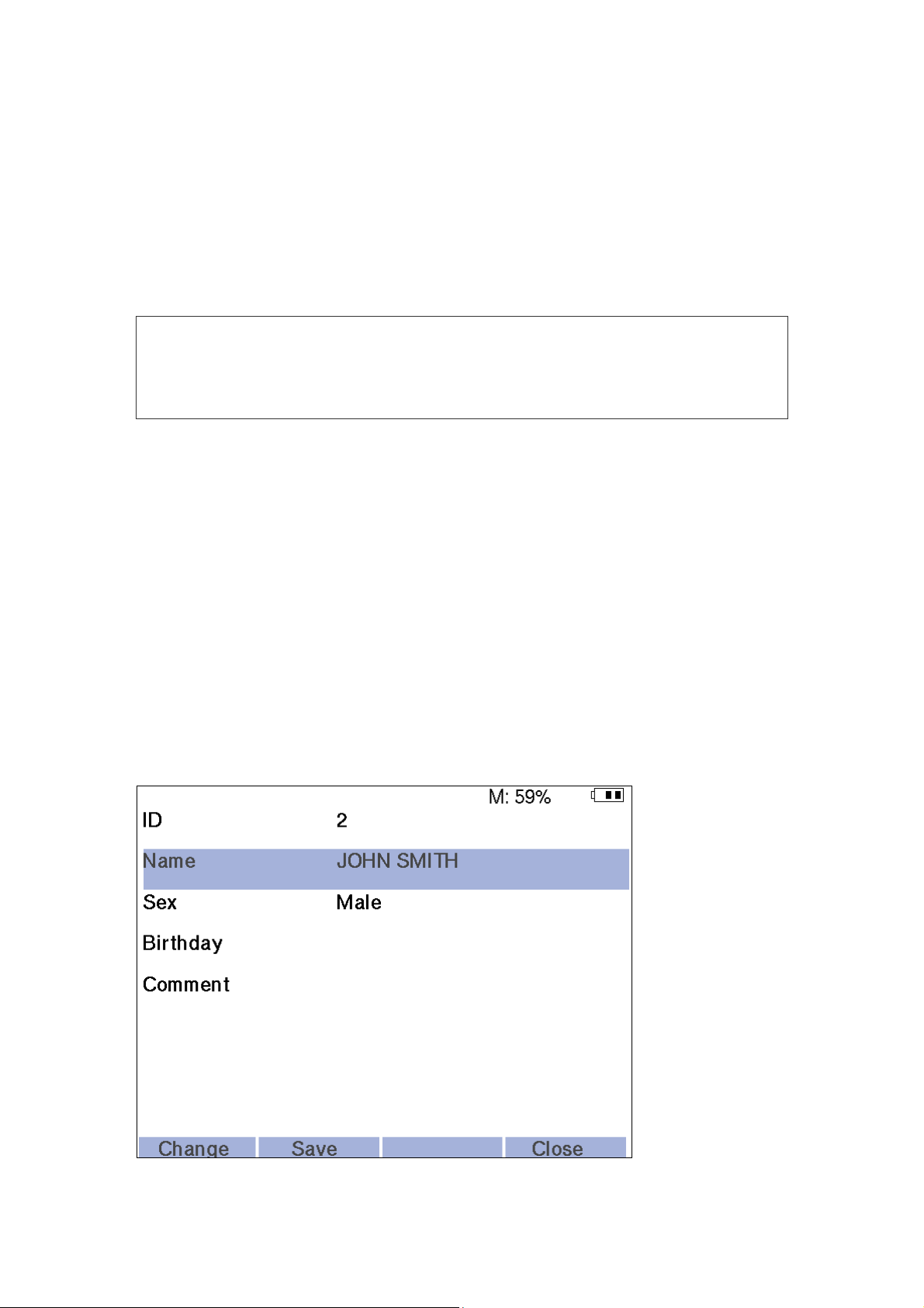
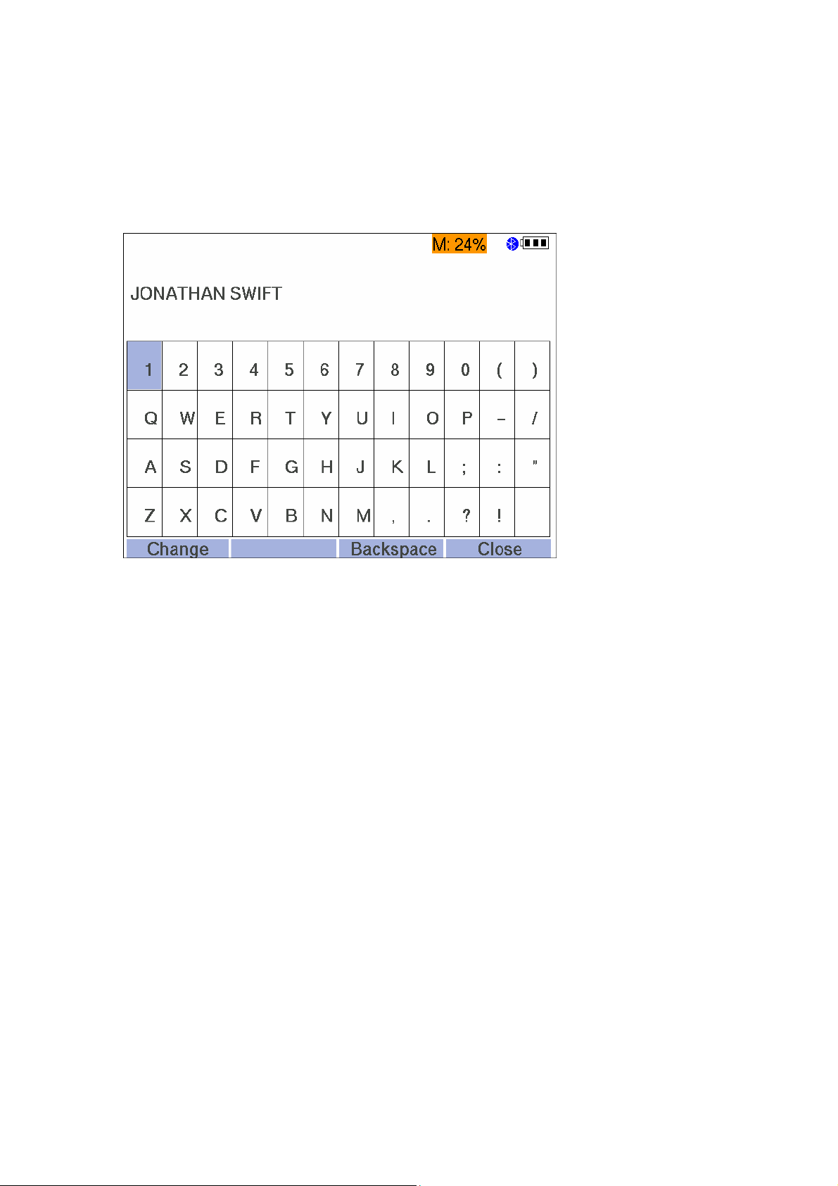
To enter the name, choose the “Name” menu item using the arrow buttons and press
“Change” button. The new window with the display keyboard (Fig. 10) will appear on
the screen. To select the required letter, shift over the keyboard using the arrow buttons, to enter this letter, press the “Select” button. If you want to remove the letter
typed incorrectly, press the “Backspace” button. After the finishing of a surname entering, press “Close” button.
Fig. 10. Display keyboard.
After that, using the arrow buttons choose the “Sex” menu item and press the
“Change” button several times till the required sex of a patient indicated right to “Sex”
menu item appears on the screen.
The next step is the entering of a patient’s date of birth. To do it, choose the “Date of
birth” menu item using the arrow buttons and press the “Change” button. After the
termination of a date entering (for example, “30.12.05”), press the “Close” button.
If there are any special data concerning a patient, you would like to save (name of a
doctor performing a exam, possible causes of a disease, etc.), than choose the
“Comment” menu item using the arrow buttons, press “Change” button, type the
required symbols, after that press “Close” button.
After the termination of patient’s data entering, press the “Save” button to save the
information in a device memory. To move to the main menu, press the “Close” button.
At the performing of the next exams of the given patient, you can download her/his
data from the device memory. To select a patient from the list of the already saved records, it is necessary to choose “Patient” item in the main menu using the arrow buttons. You can review the list of all the patients saved in the screening system memory
by shifting “right” and “left” arrow buttons. At that, the identification in the list (“ID” line
on the screen) will be displayed over the surname of each patient. As soon as you find
the required patient, press the “Close” button, at that you will move to the main window.
30

To switch quickly to a patient, you can use the search function by a patient name. To
do this, choose “Patient” item of the main menu using the arrow buttons and press
“Search” button. In the appeared window enter the first letters of a patient’s surname
using the virtual keyboard and press “Search” button. The device will display the list of
patients whose names start with the entered buttons or the message that a patient is
not found. If several patients are detected, select the required one using “up” and
“down” arrow buttons. As soon as the required patient is chosen, press “Close” button.
The main menu with the selected found patient will display on the screen.
If you want to change the data of a patient already saved in the list (for example, a
patient’s date of birth is not indicated and you would like to enter it), select the
“Patient” item in the main menu using the arrow buttons and press “Select“ button. In
the opened window choose the menu item you would like to change (for example,
“Date of birth”) using “up” and “down” button keys, and press the “Change” button.
After finishing of the data entering, press the “Save” button and then press the “Close”
button to return to the main window.
To remove all the patient’s data (both personal – name, date of birth, sex, comments
and exam data) choose the patient from the list (see above) and press the “Delete”
button in the main window. At that, the dialog box with the request concerning the
removal of the entire patient’s data will appear on the screen. To confirm the removal,
press “Yes” button, to cancel the removal, press “No” button.
Functioning
In the result of this operation fulfillment (if you press “Yes” button) the
ENTIRE patient’s data such as name, surname, sex, date of birth, results of
ALL tests by ALL the techniques will be deleted. If you want to delete the
results of ONLY ONE test and save the results of other tests and patient’s
personal data, read carefully the section 5.10.2 “Removal of Test Results”.
5.5. Patient Preparation for OAE Test
To start operation on Neuro-Audio-Screen and Neuro-Audio-Screen/OAE
screening systems you should study and master OAE technique. It is especially
important for the testing of newborns and babies. The experience of application of the
existing systems for OAE registration shows that it takes about 3 month to get the
required skills for the performing of the newborns hearing screening. At the performing
of exams of newborns and infants with the use of Neuro-Audio-Screen and Neuro-
Audio-Screen/OAE screening systems it is necessary to take into consideration the
following.
The newborn should stay quiet and calm, it is usually preferred for the infant to be
asleep. To calm a baby down, you can use a baby's dummy, however, the sucking
causes the additional noise and decreases the probability of test passing.
The important stage of otoacoustic emission study is the correct placement of a probe
to the external ear canal of a patient.
The OAE probe installed well should correspond to the following requirements:
31

Hearing Screening Systems (Technical Manual)
1. It obturates the external ear canal to convert the small fluctuations of the
tympanic membrane to the pressure fluctuations which can be detected with use
of the probe microphone.
2. It prevents from record contamination with the external noise.
3. It provides the required acoustic environment for the generation of the correct
stimuli by the probe telephone.
To satisfy the above-mentioned requirements, the OAE probe should be inserted
together with the smooth replaceable ear tips. The ear tip size is selected after the
visual assessment of a patient’s external ear canal size. The delivery set of
Neuro-Audio-Screen and Neuro-Audio-Screen/OAE screening system includes
cone-shaped and mushroom-shaped ear tips. These tips are disposable and should
be thrown away after the use.
The cone-shaped ear tips are inserted deeper down into the ear canal than the
mushroom-shaped ones. Deeper insertion into the ear canal allows for the
measurement of larger emissions due to the reduced ear canal volume. However the
deep insertion of a probe can wake a newborn up and make her/him nervous.
In this case it is more preferable to use mushroom-shapes ear tips. At the application
of the mushroom-shapes ear tip, pay attention to the ear tip insertion. It should be
inserted into the ear canal, not be located near the ear canal entrance with the ear
canal opened.
Warming the ear tips prior to insertion helps to keep the baby calm.
If the ear tip is too small, it can let the noise in the external ear canal or distort the
stimulus. If the ear tip is too big, it can not be inserted to the external ear canal deep
enough. It can lead to the decrease of the signal amplitude and the probe instability
during the exam. Besides, if the ear tip is big, it is impossible to exclude the
considerable noise interference.
Ear tip should be placed on OAE probe completely. If the ear tip ends in horn widening of a hole, it should be placed on a probe completely so that the horn beginning
should be located on the same level with acoustic lines holes. If the ear tip does not
end in the horn widening, it should be placed on a probe so that it cut should be located on the same level with acoustic lines holes (Fig. 11). The ear tips sticking out
the acoustic lines can cause the additional fluctuation of stimulus signal.
32
Fig. 11. Ear tip placement on the probe.

The removal of the ear tip is performed in the following way. Holding the nozzle
latches of OAE probe, slide the ear tip off according to Fig. 12.
Fig. 12. Correct removal of ear tip.
To avoid the break of drive latches, hold the OAE probe for the latches,
other fingers positions during the ear tip removal are not recommended!
Functioning
Fig. 13. Incorrect removal of ear tip.
When the probe is inserted into an ear, its end should not be set against the wall of
the external ear canal, because it prevents from the stimulus emerge and/or OAE
registration. Such situation can be easily detected by watching the curve shape on the
stimulus panel.
To register TEOAE in newborns, it is necessary to calm a baby down and make
her/him keep quiet and calm. The external ear canal of the newborns can close during
the OAE probe insertion. To prevent it, draw of the lobe of the auricle back and down
very carefully to level the ear canal. Examine the external ear canal to make sure that
it is opened and insert the OAE probe closely. At the moment of the OAE probe
insertion it is recommended to turn the OAE probe so to direct the probe cord to the
forehead. After the insertion, rotate the OAE probe (without leaving the auricle) so to
place the probe cord under 45° to the vertex. After that, leave the auricle.
The ears of the newborns are often wet or contain the extraneous masses. If the good
stimulation was not obtained at the first insertion of a probe, replace the ear tip with
33

Hearing Screening Systems (Technical Manual)
these extraneous masses by the new one and try again. The correctness of the OAE
probe insertion at TEOAE exam can be checked indirectly by the stimulus shape.
The Fig. 14 a) represents the oscillating stimulus shape. It does not match to TEOAE
registration. In the ear of adult it can be conditioned by the bad placement of OAE
probe or the atypical form of the external ear canal. In the last case the stimulus
shape should be accepted, however, try to insert the OAE probe again. The Fig. 14 b)
represents the stimulus shape at the correct placement of OAE probe for the adults.
As for the newborns, the additional fluctuations of stimulus can always be detected.
The Fig. 14 c) shows the admissible level of fluctuations of the newborn.
a) b) c)
Fig. 14. The stimulus shape (1).
The Fig. 15 a) demonstrates the effect of the excessive approach of the OAE probe to
the wall of the external ear canal or other barrier. The slow round low-frequency wave
following the initial sharp peaks is characteristic for this condition. In this case the
OAE probe should be reinstalled. The Fig. 15 b) shows the impact of the excessive
noise to the stimulus shape. The cause can be in too free OAE probe installation allowing the penetration of the external noise to the external ear canal or noises emitted
by the patient. The typical sounds emitted by the patient include breathing, swallowing
or tooth-grinding.
a) b)
Fig. 15. The stimulus shape (2).
5.6. TEOAE Test
34
After the selection of a patient in the list or entering new data about a patient, choose
the TEOAE technique and an ear for the exam performing (right or left) in the main
menu using the arrow buttons. It is desirable to perform it before the OAE probe insertion to the ear of a newborn not to disturb her/him again. The OAE probe installation
should be performed according to the recommendations given in the section 5.8
“Patient Preparation for OAE Test”.
Press the “Select” button. Just after the test start, the device switches to the OAE
probe fitting control mode. The TEOAE test window appears on the display (Fig. 16).
It is divided into three parts. The stimulus shape is displayed in the top part of the

window, its spectrum is represented in the left bottom part of the window. The right
bottom part of the window contains the information displaying panel. Besides, the top
part contains a status line and the bottom one has the active menu line. The information displaying panel contains two linear scales: the one is for the displaying of the
acoustic meatus volume (“volume”) and the other one is for the noise level displaying
(“noise”). If the noise level or the volume exceeds the admissible bound, the corresponding scale becomes red, if it is does not, it is of the greed color. When the OAE
probe is fitted correctly, both scales are in the green area.
If during a short-term check the device detects that the OAE probe is fitted bad, the
“Check probe fitting” message will appear above the stimulus shape curve. In this
case it is necessary to press the “Close” function key, reinstall the OAE probe and
start the test again.
Functioning
Fig. 16. TEOAE test window (1).
Note: control passing of the OAE probe fitting does not guarantee its correct setting because
the device can not follow the situation when the probe tip is fit against the wall of the ear canal
or when the canal is closed, for example, by the impacted cerumen.
If the device considers that the OAE probe is fitted correctly, it will switch to the mode
of the stimulus intensity tuning. The information panel will display the “Stimulus
calibration” message. The stimulus shape is displayed in the top part of the window;
its spectrum is represented in the left bottom part of the window.
35

Hearing Screening Systems (Technical Manual)
After the stimulus intensity tuning, the device switches to TEOAE registration mode.
The window displayed in this mode is given in the Fig. 17.
Fig. 17. TEOAE test window (2).
The top part of the window represents the shape of the averaged response, the left
bottom one displays its spectrum. The color gamma depends on the selected ear: the
blue one is for the left ear, the red one is for the right ear. The two curves of response
(A and B) are displayed. Their coincidence testifies of the OAE presence, their
difference shows the level of the residual noise. The response spectrum has two
areas: the dark one represents the noise level, the light one represents the response
level in those areas where it exceeds the noise level. The message “Acquisition”
appears on the information panel.
Besides, the following information is displayed here:
The number of the averaged responses/number of artifacts is located against the
“Stim./Art.” label. The big number of artifacts indicates either the strong external
acoustic noise or bad probe fitting. When the number of artifacts exceeds the
specified number of averaging (1000 by default), the message “Too much noise”
appears on the screen. In this case the test should be repeated in calmer
conditions or after the reinstallation of a probe.
36
Stimulus stability is against the “Stability” label. The ideal variant is when it is
equal to ”1”. The stability lesser than 0.9 indicates that the probe changed
considerably its position during the registration process. If OAE was not detected
at that, i.e. the “REFER” signature appeared on the information panel after the
test termination, repeat the test after the probe resetting; at that follow the probe
position. It should be stable.
The level of the averaged response, in dB SPL is opposite the “A&B” label. It is
the reference information about the total OAE amplitude in case the A&B value

exceeds the total level of А-В noise. If the reproducibility criteria (“Reproducibility,
%”) is set in TEOAE settings, the reproducibility coefficient will be displayed instead of the given criteria in percents. The reproducibility coefficient reveals the
correlation between odd and even curves of a signal.
Total residual noise level, in dB SPL is opposite the “A-B” label. The residual
noise level decreases in the process of the averaging. If OAE is not detected, i.e.
the “REFER” signature appears on the information panel after the test
termination, and the residual noise level exceeds 10 dB, it indicates highly
enough level of the external acoustic noises and means that the test should be
repeated in calmer conditions or after the probe resetting.
The bottom part of the information panel contains the table of OAE presence by
frequencies. The top line marked by “F” letter contains 1, 2, 3, 4 and 5 kHz
frequencies. The middle line marked as “SNR” displays the current signal-tonoise ratio on the given frequency (in dB) detected with the use of the digital
bandpass filter. The OAE presence on the given frequency is marked by
““ ”symbol. The criterion of its presence is the signal/noise ratio exceeding 4 dB.
The general criterion of test passing is the OAE emergence on three of five
frequencies. In this case the test is over and the “PASS” signature appears on the
information panel. If during the specified number of averaging (1000 by default),
OAE is not detected, the test is stopped and the “REFER” signature appears on
the information panel.
Functioning
After the test termination, you can print the result on the wireless thermal printer by
pressing “Print” button. Before printing make sure that the printer is switched on and is
in the operating zone (up to 10 meters in the direct visibility conditions).
The exam can be closed by pressing “Close” button. At that the message box “Save
exam?” will appear on the screen. Press “Yes” button if you want to save the test
results or “No” button if you don’t. After that, you will return to the main menu.
Note: the “Close” button can be pressed at any moment of test performing. If the test is not
over, you will return to the main menu, at that, the test results are not saved.
5.7. DPOAE Test
After the selection of a patient in the list or entering new data about a patient, choose
the DPOAE technique and an ear for the exam performing (right or left) in the main
menu using the arrow buttons. If a patient is a newborn, it is desirable to perform it before the OAE probe insertion to the ear of a baby not to disturb her/him again. The
OAE probe installation should be performed according to the recommendations given
in the section 5.5 “Patient Preparation for OAE Test”.
Press “Select” button. Just after the test start, the device switches to the OAE probe
fitting control mode. The DPOAE test window appears on the display (Fig. 18). It is divided into three parts. The stimulus shape is displayed in the left part of the window,
the information panel is in the right one and the stimulus spectrum displaying window
37

Hearing Screening Systems (Technical Manual)
is just under the information panel. Besides, the top part contains a status line and the
bottom one has the active menu line.
The information panel contains two linear scales: the one is for the displaying of the
acoustic meatus volume (“volume”) and the other one is for the noise level displaying
(“noise”). If the noise level or the volume exceeds the admissible bound, the
corresponding scale becomes red, if it is does not, it is of the green color. When the
OAE probe is fitted correctly, both scales are in the green area. If during a short-term
check the device detects that the OAE probe is fitted bad, the “Check probe fitting”
message will appear above the stimulus shape curve. In this case it is necessary to
press the “Close” function key, reinstall the OAE probe and start the test again.
Fig. 18. Seal control mode. DPOAE test.
Note: control passing of the OAE probe fitting does not guarantee its correct setting because
the device can not follow the situation when the probe tip is fit against the wall of the ear canal
or when the canal is closed, for example, by the impacted cerumen.
If the device considers that the OAE probe is fitted correctly, it will switch to the mode
of the telephones bandpass flatness calibration. In the left part of the window the
bandpass flatness of the one telephone and then the other one will appear. After that
the device will switch to the stimulus intensity tuning.
After the stimulus intensity tuning, the device switches to DPOAE registration mode.
The screen view in this mode is given in the Fig. 19. The DP (distortion product) diagram window will appear in the left part of the screen. The levels of the received OAE
on each frequency will display as filled circles of the red color for the right ear and of
the blue color for the left one. The grey filled triangles show the noise level. The list of
the frequencies will appear on the information panel. During the testing the “PASS”
( ) or “REFER” ( ) symbol will appear opposite each frequency. If the considerable noise or nonstable OAE probe position prevents from the results achieving, the
symbol “?” will appear. Besides the information panel contains the “N” linear scale to
38

display the noise level and the “St.” indicator of the OAE probe fitting stability in the
form of a circle ( ) which becomes green at the normal stability and does red if it is
bad. By the analogy with the seal control mode, the noise scale should be in the green
area and the stability indicator should be green. If the noise scale or the stability indicator becomes red, the current data are considered to be artifact and do not participate in the OAE selection.
During the registration process the circle and the triangle representing the OAE and
noise levels correspondingly on the current frequency appear in the DP diagram
window. They start moving up and down showing the process of OAE selection till the
specified ratio signal/noise is achieved or the specified time of one point registration
expires. After that the “PASS” or “REFER” signature appears on the information panel
opposite the corresponding frequency, and the device continues the testing on the
next frequency. As soon as all the frequencies are tested, the screening system
decides whether the test is passed or not. The corresponding signature will appear in
the top part of the screen.
Functioning
Fig. 19. The screen view in the DPOAE registration mode.
After the test termination, you can print the result on the wireless thermal printer by
pressing “Print” button. Before printing make sure that the printer is switched on and is
in the operating zone (up to 10 meters in the direct visibility conditions).
The exam can be closed by pressing “Close” button. At that the message box “Save
exam?” will appear on the screen. Press “Yes” button if you want to save the test
results or “No” button if you don’t. After that, you will return to the main menu.
Note: the “Close” button can be pressed at any moment of test performing. If the test is not
over, you will return to the main menu, at that, the test results are not saved.
39

Hearing Screening Systems (Technical Manual)
5.8. Patient Preparation for ABR Test
To start operation on Neuro-Audio-Screen screening system one should study and
master ABR technique. It is especially important for the testing of newborns and
babies.
The quality of ABR test performing depends on many factors. Apart the device
functioning, the main factors to get the reliable and correct test results are the
preparation quality and patient’s condition. It is better to test a patient when she/he
sleeps. The newborn is recommended to be tested in between the feedings, when a
baby unlikely wants to suck or perform other artifacts connected with the muscle
activity. It is better to place the electrodes in a way described in this section below
before a newborn falls asleep. Though the testing by ABR technique is not so much
sensitive to the acoustic noise in comparison with OAE, however, it is desirable to
make no noise during the test performing. It is strongly recommended to perform the
testing at the disconnected external power supply of the device and away from the
electromagnetic noise sources such as the electric wiring and the electrical
appliances.
The places for the electrodes setting should be degreased and treated by the
electrode abrasive paste for skin preparation to decrease the skin impedance. The
paste remnants can be washed by the alcohol, and the skin should be dried. In case
the reusable cup electrodes are used, the cups should be filled with adhesive paste
before the placement. The electrodes can be fastened by the adhesive plaster to
provide the better fixation.
The electrodes should be placed in a following way: the red one (noninverting) is on
the forehead, the black one (inverting) is on the mastoid near the ipsilateral ear
(where the stimulus is delivered), green one (ground) is on the mastoid near the contralateral ear. It is admissible to place the ear electrodes not only on the mastoid but
other places such as earlobe or ear canal. The example for the left ear is given of the
Fig. 20.
40
Fig. 20. The schematic of the electrodes placement at ABR registration (electrodes arrangement for the
left ear testing).

The alternative scheme of the electrodes placement is possible: the red one (noninverting) is on the forehead, the black one (inverting) is in the middle of nucha, the
green one (ground) is on the cheek (Fig. 21).
Fig. 21. The Alternative schematic of the electrodes placement at ABR registration.
At the beginning of testing the electrode impedance is checked automatically, and in
case it exceeds 5 kΩ, the testing is not started. If the satisfactory impedance is not
achieved, the repeated preparation of a patient’s skin and resetting of the electrodes
may be required.
Functioning
The OAE probe (by default), the headphones or the insert earphones may be used as
an auditory stimulator. The OAE probe application is analogous to the one described
in section 5.5 “Patient Preparation for OAE Test”. When using the insert earphones,
please, make sure that the front tubes are clean and the sound passes through them.
Put the foam ear tips on the front tube adapters, press it out with your fingers to fit the
ear canal, insert it into the ear and wait till it straighten to obturate the ear canal.
5.9. ABR Test
After the selection of a patient in the list or entering new data about a patient, choose
the ABR technique and an ear for the exam performing (right or left) in the main menu
using the arrow buttons. It is desirable to perform it before the OAE probe insertion to
the ear of a newborn not to disturb her/him again. The OAE probe installation should
be performed according to the recommendations given in the section 5.5 “Patient
Preparation for ABR Test”.
41

Hearing Screening Systems (Technical Manual)
Press the “Select” button. Just after the test start, the screening system switches to
the impedance measurement mode (Fig. 22).
Fig. 22. The impedance measurement window.
The current values of impedance for the electrodes “+”, “-” and “Ground – ” (kΩ) are
displayed on the screen. To the left from them the circles colored from red up to green
are drawn. If all the three circles are colored green, it means that the impedance values for all the electrodes are within the norm, and the next stage will be automatically
started in several seconds. At that, the ABR test window presented in the Fig. 23 will
appear on the screen. If the automatic transition does not occur, and the impedance
values, according to your point of view, are satisfactory for the test performing, press
“Start” button to start the testing manually.
42
Fig. 23. ABR test window.
The window is separated into two parts. The top part represents the response shape

received during the registration process on the grid background. The bottom part contains the information panel. Besides, the status line is provided in the top part of the
window, and the signature line for the buttons is located in the bottom part.
The next stage depends on the applied stimulator. If the headphones are used, the
screening system switches to the ABR registration mode, in case the OAE probe is
applied, it passes to the OAE probe fitting control mode. At that, the “Probe fitting”
signature will be displayed on the information panel in the bottom part of the screen. If
during a short-term check the screening system detects that the OAE probe is placed
bad, the signature “Check probe fitting” will appear on the information panel. In this
case it is necessary to press the “Close” button, reinstall the probe and perform the
test once again.
Note: control passing of the OAE probe fitting does not guarantee its correct setting because
the device can not follow the situation when the probe tip is set against the wall of the ear
canal or when the canal is closed, for example, by the impacted cerumen.
If the screening system considers that the OAE probe is placed correctly, it will switch
to the stimulus volume selection mode. The “Stimulus calibration” signature will
appear on the screen. The stimulus shape will display in the top part of the window.
Functioning
After the stimulus intensity tuning, the screening system switches to the ABR
registration mode, at that the signature “Registration” will be displayed in the bottom
part on the screen. The shape of the averaged response will be displayed in the top of
the window. The color gamma depends on the selected ear: the blue color is for the
left ear and the red one is for the right one. The displaying scale can be changed in
the limited range using the “up” (zoom in) and “down” (zoom out) buttons of the arrow
buttons. At that, the value of the scales, which current value is always represented in
the top left corner of the screen, is changed. The so called “scale 1-2-5” is used for
that. The visible size of the grid unit segment (in pixels) remains constant.
At the very ABR curve onset, the stimulus artifact area is located. Its duration is
specified in the settings, and it is not considered at the signal parameters calculation.
At the displaying, this area is represented by the straight line in the response curve
onset.
The mode of the curves displaying can be changed cyclically by the “View” button
pressing. There are three modes of the displaying: sum averaged curve, even and
odd averaged curves (A and B buffers), native curve. By default the mode of the even
and odd averaged curves displaying is activated (as in the Fig. 25). The two response
curves (A and B) are displayed; their coincidence testifies the ABR presence, and
their difference shows the residual noise level.
Two scales are located leftward on the information panel. The top scale “ABR” indicates the integral criterion of ABR presence calculated on the basis of Fsp, signal-tonoise ratio and residual noise level parameters. In the recording process the scale
color is red until the ABR presence criteria is achieved. As soon as this criterion is
achieved, the scale becomes green, the averaging is stopped and the signature
“PASS” appears on the information panel top. The bottom scale “EEG” indicates the
current level of EEG and noises. The lower is the level, the quicker is averaging. If the
43

Hearing Screening Systems (Technical Manual)
level is normal, the scale color is green. If it exceeds the specified rejection threshold,
the scale becomes red and the current epoch is rejected. Rightward the information
panel the following information is displayed:
“Stim./Art.” – the number of the averaged responses and the number of the rejected
responses.
“Fsp” – the statistical parameter of the signal by which the ABR presence is
defined. It is considered that ABR is present, if Fsp value is more than 3,1.
SNR” – the signal-to-noise ratio. This ratio should be 1.5-2 and higher for the device
to detect ABR presence.
“RNL” (“residual noise level”) – the active value of the difference between the A and
B averaged curves. The optimum value is 110 nV and lesser.
The big number of artifacts evidences either the strong external acoustic noise or the
bad probe setting. In this case the test should be repeated in calmer conditions and
after the probe resetting. The more is Fsp value, the better is the signal
“reproducibility”. The level of the residual noise decreases in the process of the
averaging. If ABR is not detected, i.e. the signature “REFER” appears on the
information panel after the test termination, and the residual noise level exceeds 110
nV, it may indicate highly enough level of the external acoustic noises and means that
the test should be repeated in calmer atmosphere or after the probe resetting
When the values of all the calculated parameters exceed the liminal ones, the registration is stopped and the signature indicating the test result “PASS” appears on the
information panel. The maximum number of averaging is specified in ABR test settings (see section 6.4 “ABR Settings”). If during the specified number of averaging
(8000 by default) ABR is not detected, the test is stopped and the “REFER” signature
appears on the information panel.
After the test termination, you can print the result on the wireless thermal printer by
pressing “Print” button. Before printing, make sure that the printer is switched on and
is in the operating zone (up to 10 meters in the direct visibility conditions).
The exam can be closed by pressing “Close” button. At that, the message box “Save
exam?” will appear on the screen. Press “Yes” button if you want to save the test
results or “No” button if you don’t. After that, you will return to the main menu.
Note: the “Close” button can be pressed at any moment of test performing. If the test is not
over, you will return to the main menu, at that, the test results are not saved.
5.10. Review, Printing and Removal of Results
The test results are the test data by one of the available techniques performed once.
That means if you performed five tests by one of the techniques, you will get five results. It is important for the principle understanding of the results saving, printing and
removal. For example, the removal of one test result will not lead to the removal of all
the performed tests results.
44

The test results are saved in the device memory separately for each patient. The
number of the tests saved in the device memory is not less than 200. The saving of
several results by several techniques is possible for one patient.
5.10.1. Review and Printing of Test Results
To review, it is necessary to select a patient from the list, than in the main window
choose the required technique and side using the “up” and “down” arrow buttons.
To the right of the test techniques, the list of the saved exams is represented
(Fig. 24).
If the check box is checked, it means that the test is passed (the result is positive), in
case the check box is unchecked, the test is failed. The first figure indicates the
sequence (order) number of the current selected exam, the second one (located after
the symbol “/”) indicates the total number of the saved tests by the present technique
for the given patient. Further the date of the exam performing in “month-day-year”
format is presented.
Functioning
Fig. 24. The exam selection for the review/printing.
The selection of the exam from the list is performed by the “left” and “right” arrow buttons, at that the date of the test and its order (or sequence) number (the first number
in the displayed line) will be changed.
45

Hearing Screening Systems (Technical Manual)
After selection of the required exam, press the “View” button. The exam result and all
the required data (Fig. 25, Fig. 26, Fig. 27) will appear on the screen. If you want to
print the test result on the printer, press “Print” button. To terminate the review, press
“Close” button.
At the review of the ABR test, you can change the vertical scale using the “up” and
“down” arrow buttons. The “View” button serves for the switching between the modes
of the curves displaying on the screen. There are two modes of the displaying: sum
averaged curve (Fig. 26) and even and odd averaged curves (A and B buffers)
(Fig. 25). By default the mode of the even and odd averaged curves displaying is activated. The two response curves (A and B) are displayed; their coincidence testifies
the ABR presence, and their difference shows the residual noise level.
Fig. 25. The review of ABR test results (1).
Fig. 26. The review of ABR test results (2).
46

Fig. 27. The review of TEOAE test results.
Functioning
Fig. 28. The review of DPOAE test results.
At the “Print” button pressing, the Bluetooth wireless connection is
activated automatically. After the printing termination, the connection
deactivates that is why there is no need to change Bluetooth settings in the
“Settings” menu.
If you want to review/print the results of other test, choose this test and press the
“View” button.
The printing of the results is also possible from the main menu. To do this, select a
patient in the main menu, choose the exam and press “Print” button.
47

Hearing Screening Systems (Technical Manual)
There are two types of the reports: complete and brief (see the report descriptions in
the sections “TEOAE Report Description”, “DPOAE Report Description”, “ABR Report
Description”). The report type for printing can be selected in the printer settings. The
brief report type allows to use the printer paper more efficiently.
The modern thermal printers use thermal paper for the printing. Do not
expose the printed results to sunlight or heat. Printing on thermal paper
fades with exposure to light or heat. Keep the printing in the cool place
protected from the direct sunlight.
5.10.2. Removal of Test Results
This paragraph describes the way of removal of ONE patient’s test results. To delete
ALL the results of ALL tests and patient’s personal data, see the section
5.4. “Entering of Personal Data of New Patient, Selection of Patient from Database,
Removal of Patient Data”.
To remove the test results, choose the patient from the list, then select the technique
and an ear using “up” and “down” arrow buttons in the main menu, after that select the
required exam which you would like to delete using “right” and “left” buttons and press
the “Delete” button. At that, the dialog box with the request concerning the removal of
test results will appear on the screen. To confirm the removal, press “Yes” button, to
cancel the removal, press “No” button.
48

5.10.3. TEOAE Report Description
The complete report is represented in the Fig. 29.
Functioning
Fig. 29. The view of the TEOAE complete report.
The report consists of the following components:
1. Name of a patient if it was entered.
2. Date of birth if it was entered.
3. Date of the test performing based on the settings of the internal clock. If the
clock is set correctly, the date in the report will also be correct.
4. Ear (right/left).
5. Test result (pass/refer).
6. Stimulus intensity during the exam in dB SPL.
7. OAE probe stability during the exam.
49

Hearing Screening Systems (Technical Manual)
8. Amplitude of the received total response (in dB), or reproducibility coefficient,
%.
9. Amplitude of the received total noise (in dB).
10. Analysis table column by frequencies in which the frequency (in kHz) is given.
11. Analysis table column by frequencies in which the signal-to-noise ratio (in dB
SRL) on the given frequency is given.
12. Analysis table column by frequencies in which the OAE presence/absence on
the given frequency is shown. The * symbol means the OAE presence and its
absence denotes the OAE missing.
13. Stimulus shape.
14. Stimulus spectrum.
15. Response shape.
16. The response (transparent) and noise (vertically hatched) spectrum.
The brief report form differs in the absence of the 7-9 and 13-16 elements.
5.10.4. DPOAE Report Description
The complete report is represented in the Fig. 30.
50
Fig. 30. The view of the DPOAE complete report.
The report consists of the following components:

1. Name of a patient if it was entered.
2. Date of birth if it was entered.
3. Date of the test performing based on the settings of the internal clock. If the
clock is set correctly, the date in the report will also be correct.
4. Ear (right/left).
5. Test result (pass/refer).
6. Column with f2 frequencies (in kHz).
7. Column with tone levels on f1/f2 frequencies (in kHz).
8. Column with the results by frequencies. If the emission on the given frequency
is presented, it is indicated by the symbol, if not – by symbol. If the
considerable noise or nonstable OAE probe position prevents from the results
achieving, the symbol “?” will appear.
Functioning
9. Column with signal-to-noise ratios (in dB SPL).
10. Distortion product diagram (DP-gram). The line with circles indicate the
emission on the distortion product frequency and the line with the triangles
denote the noise.
The brief report form differs in the absence of distortion product diagram.
51

Hearing Screening Systems (Technical Manual)
5.10.5. ABR Report Description
The complete report is represented in the Fig. 31.
Fig. 31. The view of the ABR complete report.
The report consists of the following components:
1. Name of a patient if it was entered.
2. Date of birth if it was entered.
3. Date of the test performing based on the settings of the internal clocks. If the
clock is set correctly, the date in the report will also be correct.
4. Ear (right/left).
5. Test result (pass/refer).
6. Stimulus volume during the exam in dB nHL.
7. Frequency of the stimulus delivery.
8. Criterion of the Fsp test passing.
52
9. Criterion of the test passing – signal-to-noise ratio (in dB SPL).
10. Criterion of the test passing – floor noise, active value in nV.

11. Scale value.
12. Response shape, odd/even curves.
The brief report form differs in the absence of the 9-12 elements.
6. Settings
The Neuro-Audio-Screen and Neuro-Audio-Screen/OAE screening systems pro-
vide the possibility to change different settings. Pay attention, that OAE and ABR settings are specified by default, that is why there is no need to change these parameters
without reason. If you changed the OAE and/or ABR registration parameters and want
to return to the standard parameters of all the techniques, press “Standard” button in
the “Settings” menu of OAE and ABR techniques. To do this, select the “TEOAE settings”, “DPOAE settings” or “ABR settings” item in the settings menu using “down” arrow button and press the “Select” button. After that, press “Standard” button. At that,
the dialog box for the conforming of the standard settings application for OAE and
ABR tests will appear on the screen. To set the default settings, press “Yes” button, to
exit this window saving the previous settings, press “No” button. In case you press
“Yes” button, the OAE and ABR settings will switch to default ones specified below. If
you want to specify the standard settings only for one test, see the section 6.2
“TEOAE Settings”, 6.3 “DPOAE Settings” or 6.4 “ABR Settings”.
Settings
The default settings for TEOAE test:
Template – “Noisy”
Noise level, dB SPL –60.
Intensity, dB SPL – 80.
Stimuli number – 1000.
SNR pass criteria, dB – 4.
Reproducibility, % – -.
Frequencies for pass – 3.
Stim. rate, Hz – 66.
Number of frequencies – 5 (1.0..5.0)
The standard settings for DPOAE test:
Template – “Noisy (screening)”.
Mode – 4.
53

Hearing Screening Systems (Technical Manual)
Volume level 1, dB SPL – 65.
Volume level 2, dB SPL – 55.
Noise level, dB SPL – 25.
SNR pass criteria, dB – 8.
Frequencies for pass, % – 50.
Point time, s – 5.
The standard settings for ABR test:
Template – “Screening 60 dB”.
Intensity, dB nHL – 60.
Stim. rate, Hz – 92.
Rejection threshold, µV – 90.
Artifact duration, ms – 1.
Stimulator – OAE probe.
Stimuli number – 8000;
Notch filter – 50 Hz.
54

To change the settings, it is necessary to select “Settings” item in the main menu by
pressing the “down” arrow button and press “Select” button. The “Settings” window
appearance is shown in the Fig. 32.
Settings
Fig. 32. The “Settings” menu window.
6.1. General Settings
The general settings include the following:
Report type. See the report description in the sections 5.10.3 “TEOAE Report De-
scription”, 5.10.4 “DPOAE Report Description” and 5.10.5. “ABR Report Description”.
Bluetooth.
Version – the menu item for internal software version check.
To change the report type (complete or brief), enter the “Settings” menu, choose
“Report type” item using the “up” and “down” buttons and then press “Change” button
to select the required type of the report. To exit this menu, press “Close” button.
The Bluetooth setting activates/deactivates this type of the wireless connection used
for the data transfer to the personal computer (see the detailed information in software
manual supplied with the device). To change the Bluetooth settings, enter the “Settings” menu, choose the “Bluetooth” item using “up” and “down” buttons and activate/deactivate this option by pressing the “Change” button. Wait for several seconds
till the state of this type of connection changes on the screen (the signature in “Bluetooth” menu item will change and the pictogram in the top part of the screen will highlight/disappear). To exit the menu, press “Close” button. This function should be used
only for the device connection with the computer for the data exchange. Bluetooth
on/off at printing occurs automatically (by “Print” button pressing).
55

Hearing Screening Systems (Technical Manual)
If the Bluetooth connection is activated, the operation time of the screening
system supplied from the built-in rechargeable battery lessens, that is why
disable this function if it is not required at the present moment.
6.2. TEOAE Settings
TEOAE settings include the following:
Noise level, dB SPL. Range – from 20 up to 70.
Intensity, dB SPL. Range – from 60 up to 80.
Stimuli number. Range – from 100 up to 1000.
SNR pass criteria, dB. Range – from 3 up to 10.
Reproducibility, %. Dash (is not set), 50%, 60%, 70%, 80%, 90%.
Frequencies for pass, 2 + 1 – two frequencies from 1 up to 4 kHz and one
frequency 5 kHz, 3 – any three frequencies, 4 – any four frequencies, 5 – any five
frequencies.
Stim. rate, Hz. Range – from 49 up to 66.
Number of frequencies – 5 (1.0..5.0) – 5 frequencies within the range from 1 to 5
kHz; 6 (0.7..4.0) – 6 frequencies within the range from 0.7 to 4 kHz; 6 (1.5..4.0) – 6
frequencies within the range from 1.5 to 4 kHz.
These settings are stored in the templates. The screening system provides three default templates – the set of specified parameters: “Noisy”, “Normal”, “Quiet”. To select
the template, enter the “Settings” menu and then using “up” and “down” arrow buttons,
select “TEOAE settings” menu item and press “Change” button. After that the window
represented in the Fig. 33 will appear. Switch the template using “right” and “left” arrow buttons.
56

Please pay attention that the default templates can not be changed and/or removed.
To add the template, press “New” button, enter the name of a new template and set it
up. If you want to remove the template, press “Delete” button.
Settings
Fig. 33. TEOAE test parameters setting.
To change the settings in your template, select the required setting using “up” and
“down” arrow buttons and change the value by 1 unit by pressing the “left” (-1) and
“right” (+1) arrow buttons or by 10 units by pressing “-10” and “+10” buttons.
If you want to set the standard settings, press the “Standard” button. The dialog box
with the request concerning the default settings setup will appear on the screen. Press
“Yes” button to set them or “No” button to cancel. If you press “Yes” button, the
standard settings will be set only for TEOAE test.
After finishing the settings change, press “Close” button, at that the dialog box with the
request concerning the confirmation to save the changes made in TEOAE settings will
appear. To save the changes, press “Yes” button, to exit without saving of the
changes, press “No” button.
6.3. DPOAE Settings
DPOAE settings include the following:
Mode (4, 8, 12).
Volume level 1, dB SPL. Change range – from 50 up to 70.
Volume level 2, dB SPL. Change range – from 50 up to 70.
Noise level, dB SPL. Change range – from 20 up to 70.
SNR pass criteria, dB. Change range – from 6 up to 10.
57

Hearing Screening Systems (Technical Manual)
Frequencies for pass, %. Change range – from 50% up to 100%.
Point time, s. Change range – from 0,5 s up to 5 s.
These settings are stored in the templates. The screening system provides three default templates – the set of specified parameters: “Noisy (screening)”, “Normal
(screening)”, “Quiet (standard)”. To select the template, enter the “Settings” menu, select “DPOAE settings” menu using “up” and “down” arrow buttons and press “Change”
button. After that the window represented in the Fig. 34 will appear. Switch the template using “right” and “left” arrow buttons.
Please pay attention that the default templates can not be changed and/or removed.
To add the template, press “New” button, enter the name of a new template and set it
up. If you want to remove the template, press “Delete” button.
Fig. 34. DPOAE test parameters setting.
To change the settings in your template, select the required setting using “up” and
“down” arrow buttons and change the value by 1 unit by pressing the arrow buttons
“left” (-1) and “right” (+1) or by 10 units by pressing “-10” and “+10” buttons. The “-10”
and “+10” buttons are not used for the “Mode” setting.
The “Mode” setting allows choosing the number of frequencies for testing. In the
“Screening” mode there are 4 of them – from 1,4 up to 5,7 Hz, in the “Standard” mode
there are 8 of them – from 1,4 up to 8 kHz, the “Extended” mode provides 12
frequencies – from 0,55 up to 8 kHz.
The “Volume level 1, dB SPL” and “Volume level 2, dB SPL” settings allow specifying
the intensity of the testing tone on f1 and f2 frequencies correspondingly.
The “Noise level, dB SPL” setting specifies the threshold of the artifacts rejection by
noise level.
58

The “SNR pass criteria, dB” setting specifies the criteria for test passing by
signal-to-noise ratio on the required frequency.
The “Frequencies count for pass, %” specifies the minimal percent of the frequencies
for test performing to obtain the “PASS” total test result. This setting is used together
with the “SNR pass criteria, dB” criterion to specify the general criterion for test
passing. For example, if the “SNR pass criteria, dB” is set on 4 dB and the
“Frequencies for pass, %” is done on 50%, than the test should contain at least 50%
of frequencies on which the emission is at the minimum 4 dB higher the noise level to
achieve the “PASS” result.
The “Point time, s” setting allows to specify the maximum averaging time on each
frequency. In case the criterion of passing on the given frequency is achieved earlier
than the maximum time expires, the test on this frequency is terminated earlier and
the screening system will switch to the testing of the next one.
If you want to set the standard settings, press the “Standard” button. The dialog box
with the request concerning the default settings setup will appear on the screen. Press
“Yes” button to set them or “No” button to cancel. If you press “Yes” button, the
standard settings will be set only for DPOAE test.
Settings
After finishing the settings change, press “Close” button, at that the dialog box with the
request concerning the confirmation to save the changes made in DPOAE settings will
appear. To save the changes, press “Yes” button, to exit without saving of the
changes, press “No” button.
6.4. ABR Settings
ABR settings include the following:
Intensity, dB nHL. Range – from 0 up to 100.
Stim. rate, Hz. Range – from 1 up to 100.
Rejection threshold, µV. Range – from 0 (disabled) up to 200.
Artifact duration, ms. Range – from 0 up to 5.
Stimulator – either OAE probe or TA-01, TDH-39 headphones or ER-5A, ER3-10
insert earphones.
Stimuli number. Range – from 1000 up to 8000.
Notch filter. Off, 50 Hz, 60 Hz. It allows to remove the noise emitted by alternating-
current mains.
These settings are stored in the templates. The screening system provides three default templates – the set of specified parameters: “Screening 60 dB”, “Screening 30
dB”, “Standard 60 dB”. To select the template, enter the “Settings” menu and then using “up” and “down” arrow buttons, select “ABR settings” menu item and press
59

Hearing Screening Systems (Technical Manual)
“Change” button. After that the window represented in the Fig. 35 will appear. Switch
the template using “right” and “left” arrow buttons.
Please pay attention that the default templates can not be changed and/or removed.
To add the template, press “New” button, enter the name of a new template and set it
up. If you want to remove the template, press “Delete” button.
Fig. 35. The window of ABR technique parameters setting.
To change the settings in your template, select the required setting using “up” and
“down” arrow buttons and change the value by 1 unit by pressing the arrow buttons
“left” (-1) and “right” (+1) or by 10 units by pressing “-10” and “+10” buttons.
If you want to set the standard settings, press the “Standard” button. The dialog box
with the request concerning the default settings setup will appear on the screen. Press
“Yes” button to set them or “No” button to cancel. If you press “Yes” button, the
standard settings will be set only for ABR test.
After finishing the settings change, press “Close” button, at that the dialog box with the
request concerning the confirmation to save the changes made in ABR settings will
appear. To save the changes, press “Yes” button, to exit without saving of the
changes, press “No” button.
6.5. System Settings
System settings include the following:
60
Sensitivity, mV/Pa. The change range – from 5 up to 50.
Printer type – SPRINT or UPS.
Address – the address of the printer.

Date.
Time.
Brightness – brightness of the screen highlight. Change range – from 1 up to 11.
Auto turn off, min. Change range is from 1 up to 30 minutes or dash (do not use
automatic device switch off).
Password – four-digit code can be used for the protection of OAE, ABR and system
settings from unauthorized change.
Language – allows to switch the language of menu and service information.
To change any of these settings, enter the “Settings” menu, then select the “System
settings” item using “up” and “down” arrow buttons and press “Change” button. The
window represented in the Fig. 36 will appear on the screen.
Settings
Fig. 36. The window of system parameters setting.
The “Sensitivity” parameter specifies the sensitivity of the OAE probe microphone.
Each OAE probe can have the microphone with the sensitivity differing from others.
The concrete value is marked on the label fixed on the OAE probe cable. The correct
setting of the “Sensitivity” parameter is required for the receiving of the test correct
results.
Before starting to work, make sure that the device settings contain the
same value as on a label located on OAE probe cable.
61

Hearing Screening Systems (Technical Manual)
To change the microphone sensitivity, select the “Sensitivity” menu item using “up”
and “down” arrow buttons. Change the value by 1 unit by pressing the arrow buttons
“left” (-1) and “right” (+1) or by 10 units by pressing “-10” and “+10” buttons.
To change the printer type, select the “Printer type” menu item using “up” and “down”
arrow buttons. To change the printer type, press the “Change” button till the required
one appears, at that, the printer type will change automatically on the one printer type
indicated in the already programmed list of the device.
Each printer has its unique address. To print the exam results on your printer, it is
necessary to enter it in the device. Read the printer technical manual to learn the
printer address. For example, for SPRINT printers, at the switching on the power
supply, it is necessary to press and hold the control button till the page with the printer
parameters including the printer address prints out.
To set the printer address, choose the “Address” menu item by pressing “up” and
“down” buttons and press the “Change” button. The change window of the printer address is represented in the Fig. 37.
62
Fig. 37. The change window of the printer address.
The address is 12 hexadecimal figures. It is entered in the same format it is displayed
on the screen, i.e. “AA:BB:CC:DD:EE:FF”. The figures in a position are changed by
“up” and “down” buttons pressing. You can also change the figure using the screen
keyboard. To do this, press “Change” button. The switching between the figure
positions is performed by pressing “left” and “right” buttons. After the address
entering, press the “Close” button.

To set the date, choose the “Date” menu item using “up” and “down” buttons and
press “Change” button. The date setting window is represented in the Fig. 38.
Settings
Fig. 38. The date and time setting window.
In English language the date is entered in the same format it is represented in the
menu, i.e. “MM:DD:YYYY” (month/date/year). As for other languages (French,
German and Portuguese), the date is “DD:MM:YYYY” (date/month/year). The figures
in a position are changed by “up” and “down” buttons pressing. You can also change
the figure using the screen keyboard. To do this, press “Change” button. The
switching between the figure positions is performed by pressing “left” and “right”
buttons. After the date entering, press the “Close” button.
To change the time, choose the “Time” menu item using “up” and “down” buttons and
press “Change” button. The time setting window will display on the screen. The time is
entered in the same way as date, in the format it is represented in the menu,
“HH:MM:SS” (hour/minutes/seconds). The hour value is entered in 0-24 range. After
the time entering, press the “Close” button.
To change the display brightness, choose the “Brightness” menu item using “up” and
“down” arrow buttons. The “left” arrow button will decrease the display brightness and
the “right” one will increase it.
The device provides the possibility of automatic shutdown after the specified period of
inactivity. To set up this period, select “Auto turn off, min” item using “up” and “down”
arrow buttons. The buttons “left” and “-10” decrease the time by 1 or 10 minutes
correspondingly, the “right” and “+10” buttons increase the time by 1 or 10 minutes
correspondingly. If you decrease the auto turn off time up to lesser 1 minute, the dash
will appear opposite the menu item. It means that the device auto turn off is not used,
i.e. the device will operate constantly until it is off using on/off button.
63

Hearing Screening Systems (Technical Manual)
The device provides the possibility to protect the settings from unauthorized change.
To do this, enter the password to access the settings. The four-digit code can be used
as a password. In case the password is set, you should enter it in the appeared
window to change the settings of OAE, ABR and system settings. If the entered
password coincides with the specified one, the settings can be changed, otherwise,
your access to the setting will be denied. The password specified earlier can be
disabled and the device can be switched to operating mode without password. In this
case you will not have to enter the password to change OAE, ABR and system
settings. To disable the password specified earlier, select “Password” menu item and
press “Change” button. In the appeared window press “Clear” button. You will
automatically return to editing window of system settings. In this window press “Close”
button and answer “Yes” to the question concerning the necessity of changes saving.
The screening system supports ten interface languages:
Russian.
English.
French.
German.
Portuguese.
Polish.
Spanish.
Italian.
Czech.
Slovak.
To change the interface language, it is required to open the “Settings” menu, after that
select the “System settings” item using “up” and “down” arrow buttons, then the
“Language” item by using the “up” and “down” arrow buttons and press “Change“
button to switch the interface. After that, press the “Close” button.
64
If you accidentally specified the language differing from the required one, and it is
difficult for you to orient in the menu items, follow the instructions below:
1. Switch off the screening system.
2. Switch on the screening system. The main menu window will display on the
screen.
3. Select the bottommost menu item by navigating “up” and “down” arrow buttons.
4. Press the left-most multifunctional button.

Data Exchange with Computer
5. Select the last but one menu item by pressing “down” arrow button.
6. Press the left-most multifunctional button (if the dialog box offering to enter the
figures will appear on the screen, enter the password and press the right-most
multifunctional button).
7. Select the last menu item by pressing “down” arrow button.
8. Press the left-most multifunctional button several times till the signature “English”
appears in the top part of the screen.
9. Press the right-most multifunctional button.
After finishing the settings change, press “Close” button, at that the dialog box with the
request concerning the confirmation to save the changes made in system settings will
appear. To save the changes, press “Yes” button, to exit without saving of the
changes, press “No” button.
7. Data Exchange with Computer
7.1. Screening System Connection to Computer
To exchange the data with Neuro-Audio-Screen screening system and the computer
it is necessary to provide the connection. It is required, for example, for the
downloading of the patients’ list or for the receiving of the exam results. To provide the
connection, the so called Bluetooth personal area network (PAN) is used, the pass
key “12345”. The connection procedure varies depending on the computer and
operating system. The typical order of operations (step-by-step) in Windows XP
operating system at the use of the standard Bluetooth adapter is described below. If
you use other operating system or adapter manufactured by other company, it is
necessary to follow the documentation supplied with these devices and software.
65

Hearing Screening Systems (Technical Manual)
Step 1. Activate Bluetooth on the screening system (see section 6). The screening
system should be near the computer. Find the Bluetooth item on the computer task
bar, press it with the right mouse button and in the appeared menu choose the “Join a
Personal Area Network” item (Fig. 39).
Fig. 39. Device connection with the computer. Step 1.
Step 2. If you already set the connection to the screening system, move to step 7,
otherwise the dialog box represented in the Fig. 40 will appear on the screen. Press
the “Add” button in this window.
66
Fig. 40. Device connection with the computer. Step 2.

Data Exchange with Computer
Step 3. In the appeared dialog box check the “My device is set up and ready to be
found” checkbox and press “Next” button (Fig. 41).
Fig. 41. Device connection with the computer. Step 3.
Step 4. The computer will perform searching and in some time will show the list of the
detected devices. Choose Neuro-Audio-Screen screening system in the list and
press the “Next” button (Fig. 42).
Fig. 42. Device connection with the computer. Step 4.
67

Hearing Screening Systems (Technical Manual)
Step 5. In the appeared dialog box select “Use the passkey found in the documentation” and enter the passkey “12345” (Fig. 43). Press “Next” button.
Fig. 43. Device connection with the computer. Step 5.
Step 6. The computer will exchange the passkeys with the screening system and will
inform about that. In the appeared dialog box press “Finish” button (Fig. 44).
68
Fig. 44. Device connection with the computer. Step 6.

Data Exchange with Computer
Step 7. The dialog box with the list of the devices (Fig. 45) will appear on the screen.
Choose Neuro-Audio-Screen screening system and press the “Connect” button. The
computer will connect the screening system and you will have a new session.
Fig. 45. Device connection with the computer. Step 7.
7.2. Operation with Neuro-Audio-Screen Manager
Software
The Neuro-Audio-Screen and Neuro-Audio-Screen/OAE screening systems are
supplied with the Neuro-Audio-Screen Manager software. It can function properly on
any IBM compatible computer with Intel Pentium Celeron 1 GHz (Intel Pentium IV is
recommended) processor and under control of Windows XP/Vista/7 operating
system. For the software setup there should be 1 Gb of free hard disk space and not
less than 20 Mb of free hard disk space for the exam archive. In case of operation
under control of Windows XP, the installed .NET Framework 2.0 component or
higher should be available. The Bluetooth adapter either built-in or external should be
connected to the computer.
As soon as you made a connection with the device, you can control the list of patients
stored in the device and also transfer the data of the already executed exams to the
computer. The Neuro-Audio-Screen Manager software is intended for this purpose
(further “the software”).
Connect the computer to Neuro-Audio-Screen screening system as described in
p. 7.1.
To start the operation with the program, first install it from the disk included in the
screening system delivery set.
69

Hearing Screening Systems (Technical Manual)
In case the installation disk is missing, you can always download all the
necessary components and last version of the program distributive from
our site: http://www.neurosoft.ru/eng/soft/. To get an access to the files, enter the name and the password which you can obtain in the commercial department of Neurosoft Ltd.
Insert the disk into the disk driver of your computer. As soon as the menu appears on
the screen, choose “Neuro-Audio-Screen Manager” item in it.
If the menu hasn’t appeared, open the disk content using Windows Explorer and start
AUTORUN.EXE file.
After the installation, the shortcuts for “Neuro-Audio-Screen Manager” start will
appear on the desktop and in the “Start” menu. You can use any of them.
After the program start, the main window will appear on the screen (Fig. 46).
List of exams
List of patients
Report area
Fig. 46. Neuro-Audio-Screen manager main window.
Using the program, you can carry out the transfer of patient list and performed exams
from the device to the computer, generate the list of patients for the exam performing,
print the results of the performed exams and update the device firmware.
The main window consists of the following parts: the menu, the toolbar, the patients
list, the exams list and report area.
70
The toolbar is intended for quick access to the most frequently used program
functions.
The list of patients is represented as the table with the following areas:

Data Exchange with Computer
“№” – the sequence number.
“*” – the selection area (is used to generate the reports and for exams import).
“Patient” – patient name.
“Sex” – patient sex.
“Date of birth” – patient date of birth.
Brief summary of the performed exams. Here the information concerning the
success of the test passing by TEOAE (left and right ears), DPOAE (left and right
ears) and ABR (left and right ears) techniques is displayed.
The list of exams is also represented as the table with the following areas:
“№” – the sequence number.
“*” – the selection area (is used to generate the reports).
“Date” – the date of exam performing.
“Test” – the technique of test performing.
“Ear” – the ear for which the test was performed.
“Res” – the test result (“+” – the test is passed, “-” – the test is failed, “?” – the data
is insufficient to make a decision).
71

Hearing Screening Systems (Technical Manual)
7.2.1. Receiving of Patient List and Exams
To receive the list of patients and exams from the device, it is required to activate
Bluetooth on it and make the connection as it was described above. After that it is
possible to receive the list of patients. Press button “Acquire data from the device”. The list of patients will appear on the screen (Fig. 47).
Fig. 47. List of patients.
72

Data Exchange with Computer
In this list select those patients whose exams you would like to import (or select all of
them to receive all the exams). After the patients selection, press “Import exams”
button. The dialog box asking where the information should be saved will appear on
the screen (Fig. 48).
Fig. 48. Folder selection.
After the folder selection the information saving will occur and the list of the selected
patients and also the list of performed exams will appear on the screen (Fig. 49).
Fig. 49. List of exams.
As soon as you saved the exams to the computer, you can operate with them even if
the device is switched off or disconnected.
73

Hearing Screening Systems (Technical Manual)
7.2.2. Operation with Saved Exams
To open the saved data, press “Open database” button. The dialog box for file selection will appear on the screen (Fig. 50).
Fig. 50. Database opening from the disk.
Select the folder where the information about the patients and exams is kept (pa-
cients.xml file should be available there). After the selection of the folder, the information will download to the program and display on the screen (Fig. 51).
74
Fig. 51. List of patients.

Data Exchange with Computer
7.2.3. Exam Review and Print
To review and/or print the exams, select the required rows in the list of patients and
press “Generate report” button. The exam report for all selected patients will be
generated and displayed in the report area (Fig. 52).
Fig. 52. Report of the performed exams.
To print the exam report, press “Print report” button. If some exams should be
excluded from the report, uncheck the checkboxes opposite them in the exam list
before the report generation.
7.2.4. Operation with Patients List
One of the main tasks of Neuro-Audio-Screen manager software is the control of the
patients list. You can work with the patient list at any stage (after data import from the
device, after data download from the disk and just after the program opening).
To add a new patient, use “Add patient” button or [Ins] key. The “Patient data”
dialog box will appear on the screen (Fig. 53).
Fig. 53. “Patient data” dialog box.
You can switch between the input fields using both [Tab] key and the mouse.
75

Hearing Screening Systems (Technical Manual)
Enter the required patient data and press “OK” button or use “Cancel” button if you do
not want to add the patient to the list. Also you can use keyboard keys: [Enter] key
pressing is analogous to “OK” button pressing and [Esc] button is equal to “Cancel”
one.
To edit the patient data, press “Edit patient” button. The “Patient data” dialog box
will appear on the screen (Fig. 53).
To remove a patient, click the row with her/his name with the mouse (Fig. 54).
Fig. 54. Patient removal from the list.
Press “Delete patient” button or [Del] key. Confirm a patient removal in the appeared dialog box (Fig. 55) by pressing “OK” button or deny the removal using “Cancel” button.
Fig. 55. Request to delete a patient.
The list of patients can be saved to the disk using “Save patients list” button. To
do this, in the appeared dialog box (Fig. 48) choose the folder where to save the list of
patients and press “OK” button to save it or “Cancel” button to close the window without saving. Afterwards, to return to the patients list, open it from the disk. This procedure is described in section 7.2.2 “Operation with Saved Exams”.
76

Data Exchange with Computer
At any moment you can create the new patients list. To do this, press “Create new pa-
tients list” button. If the current patients list already contains the records, the
warning (Fig. 56) will appear on the screen.
Fig. 56. Request how to act at the new patients list creation.
If you press “Yes” button, the current list will be saved to the disk. If you choose “No”,
the current list will not be saved, the new patients list will be created. In case you
press “Cancel” button, the current list will remain on the screen, at that the new one
will not be created.
After creation of the patients list, it can be transferred to the device. It is performed
with the use of “Send changes to device” button. Bluetooth should be activated
on the device and the connection should be established.
If at that moment the records about the patients already exist in the device database,
the program will offer to add the patients from the created list to the patient in the device or remove all the records in the device and generate completely new list (Fig. 57).
Fig. 57. Request how to act at patients list saving to device.
If you press “Yes” button, the patients just entered to the program will be added to the
ones already existing in the device. If you press “No” button, the current patients list
which already exists in the device, will be refreshed by the new one. If press “Cancel”
button, the patients list in the device will remain unchanged.
77

Hearing Screening Systems (Technical Manual)
7.2.5. Service Functions
Service functions include the switching of program interface language, updating of
device firmware and settings.
The program allows switching the interface language if other language was selected
during the installation or it is required to switch temporarily from one language to another one. To change the program language, open “Service” menu and choose “Select Language:” item. The “Select Language” dialog box will appear on the screen
(Fig. 58).
Fig. 58. Selection of program interface language.
Choose the required language and press “OK” button to set the selected language or
“Cancel” button if you do not want to change the manager language.
Some manager functions can be protected by the password. To do this, specify the
password in the manager settings. Click “Service” menu with the mouse and select
“Settings” item. The “Settings” dialog box will appear on the screen (Fig. 59).
Fig. 59. Manager settings.
78

Data Exchange with Computer
To change the password (or set it for the first time), enter the password in “Password:”
input box and confirm it in “Re-type password:” input box. Then press “Set password”
button. If the password and its confirmation coincide, the password will be set. If you
check the “Protect settings and service mode by password” checkbox, you will have to
enter the password to change the settings and/or update device firmware. The “Enter
password” dialog box is represented in Fig. 60.
Fig. 60. Password entering.
If the manager offers to enter the password, the further operation will be possible only
after the correct password entering.
7.2.6. Firmware Updating
Using the manager, you can update the device firmware. To do this, switch on the device in the updating mode. Switch off the device if it is on. Press the most left button located under the screen and holding it, press device on/off button. As soon as the screen
highlights, release the button under the screen. After that, the device will download in a
special mode intended for updating (Fig. 61).
Fig. 61. The updating mode.
As soon as the device is switched on in the updating mode, you can start to the firmware updating directly. Preliminary it is required to establish the connection as described in section 7.1 “Screening System Connection to Computer”.
79

Hearing Screening Systems (Technical Manual)
The updating is activated by pressing “Update device firmware” button. Depending
on the manager settings, the dialog box for the password entering can appear on the
screen.
Only the specialists can update the device firmware as far as the device
operation can be violated.
To update the software, the key file is provided which is supplied with
Neuro-Audio-Screen manager distributive. It detects the device with serial number
which can be updated using the function of firmware update. After the updating run,
the program checks the availability of this key. In case the key is not detected or does
not correspond to the device being updated, the warning message will appear on the
screen (Fig. 62).
Fig. 62. The warning message concerning the key file mismatch to the device.
If such message appears on the screen, address to your dealer and inform of the
serial number of the device (it is given in the text of the warning message in brackets).
If the key was accepted, the dialog box for the updating file selection will appear on
the screen (Fig. 63).
80
Fig. 63. The selection of the updating file.

Data Exchange with Computer
The file name can differ from the one indicated in the figure. The updating files are
one and the same for all versions of Neuro-Audio-Screen device. After the file selection the program will update the device firmware. During the updating it is prohibited to
switch off the computer or disconnect from it. If the updating file is damaged, the error
message will appear on the screen (Fig. 64).
Fig. 64. Incorrect updating file.
To receive the correct updating file, address to your dealer.
After the updating finishing, you must switch off the device and after that
switch it on.
To terminate the operation with the program, press button located in the right top
corner of the window.
81

Neuro-Audio-Screen, Neuro-Audio-Screen/OAE Hearing Screening Systems (Technical Manual)
8. Troubleshooting
Table 4. Troubleshooting
Trouble Symptom Possible Cause Way of Removal
The screening system does not
switch on when supplied from
the rechargeable battery.
The screening system does not
switch on while supplied from
the power supply unit when
the rechargeable battery is
discharged.
The screening system does not
switch off at on/off button
pressing.
The screening system switches
off spontaneously at
the operation from
the rechargeable battery.
If you press the on/off button, the
screening system switches on
and after releasing it, it switches
off at once.
After the switching on the
screening system does not
respond to the button pressing.
The printer does not respond to
the “Printer” button pressing.
The printer does not print
the data.
The rechargeable battery is
discharged.
The power supply unit is out of
order.
The power supply unit produced
by other manufacturer is used
The voltage (220/230 V) in the
plug is not supplied.
The process of saving or printing
takes place.
The error of the screening
system switching off.
The rechargeable battery is
discharged.
The time of the on/off button
pressing is not enough,
The rechargeable battery is
discharged.
The on/off button is stuck. Press the on/off button several
The printer is switched off.
The printer is too far from the
screening system.
The printer settings in the
screening system are not correct.
The paper is finished. Insert the new paper roll. If the
Connect the power supply unit.
Replace the power supply unit on
the operable one.
Apply the power supply unit
included in the delivery set.
Insert the power supply unit to
other plug with 220/230 V.
Wait for several minutes and try
again.
Disconnect the power supply unit
if it is connected to the device.
The screening system will switch
off.
The battery discharge limiting
circuit activates in the screening
system. Connect the power
supply unit and charge the
rechargeable battery.
Keep the button in a pressed
position more than 3 seconds at
the switching on (till the image
appears on the screen).
The bound circle of the battery
discharge activates in the
screening system. Connect the
power supply unit and charge the
rechargeable battery.
times.
Switch on the printer.
Locate the printer near the
screening system.
Change the settings of the printer
(see the section 6. “Settings”).
paper comes out without the text,
it means that it is inserted by the
wrong side. Extract the paper
and insert it again by the end
going out the roll bottom.
82

Table 4. Continued
Trouble Symptom Cause Way of Removal
ABR testing provides unreliable
results.
When supplied from
the rechargeable battery,
the device discharges quickly.
When you start any test
the “Memory is full” error
appears.
The power supply unit is
connected to the screening
system.
The rechargeable battery is not
operable.
The free space is not enough to
start the testing.
Disconnect the power supply unit
from the screening system.
Replace the rechargeable battery
in the service center of Neurosoft
Ltd. Please, pay attention that
the replacement of the battery
must be carried out in the service
center of Neurosoft Ltd. as far as
this procedure results in the
electronic unit opening and you
may loose the warranty if you
address to other service centers
or open the unit yourself.
Remove the unnecessary test
results (see the section 5.10.2.
“Removal of Test Results”) or all
the patients’ data whose exam
result storing is not required (see
the section 5.4. “Entering of
Personal Data of New Patient,
Selection of Patient from
Database, Removal of Patient
Data”).
Troubleshooting
In case of other troubleshooting emergence and also if the troubleshooting can not be
eliminated with the use of the device control tools or by restart, it is necessary to address to
the Service center of Neurosoft Ltd.
83

Neuro-Audio-Screen, Neuro-Audio-Screen/OAE Hearing Screening Systems (Technical Manual)
9. Technical Servicing
9.1. General Requirements
Safety measures when servicing Neuro-Audio-Screen and Neuro-AudioScreen/OAE screening systems conform to the ones described in the section
1 “Important Safety Instructions”.
The qualification requirements to the medical staff are listed in the section 4.3.
“Requirements to the Personnel Conducting Mounting and Setting”.
The screening system servicing in the process of operation includes the external
examination, check of jacks and cables, removal of contaminations from the units’
surface using wet fabric. These operations can be performed by the personnel
executing the screening system exploitation, and in case of the trouble detection,
address to the technical personnel.
The servicing of the bought articles included in the screening system is conducted
according to user and technical manuals or typical rules.
When detecting the troubles it is recommended to use the information given in the
section 8 “Troubleshooting”.
The screening system should be serviced while the operation on the device and also
maintained regularly. The volume of technical servicing is indicated in chapter 9.2
“Maintenance Works”.
The delivery set check of Neuro-Audio-Screen and Neuro-Audio-Screen/OAE
screening systems is done by conformity to the device packing report.
9.2. Maintenance Works
The maintenance works include the external examination, check of connectors and
cables, removal of contaminations from the units’ surface using wet fabric.
The OAE probe tip is replaced only at clogging. Three tips for the replacement are
supplied with the screening system.
9.3. Cleaning and Desinfection
These screening systems may be wiped clean with a damp cloth using a detergent or
mild antiseptic solutions applied in the hospitals. Take care not to put excessive
pressure on the display window. Do not allow any fluid to enter the device. Do not use
the isopropyl alcohol or other dissolvent for the device cleaning.
84

Technical Servicing
9.4. Device Functioning Check Using Test Cavity
The check should be performed in a quiet room. To check the functioning in TEOAE
mode, connect the OAE probe to the device and insert it in test cavity. Switch on the
device. Run TEOAE test by pressing “Select” button. Observe the TEOAE acquisition
process (see the description in section 5.6 “TEOAE Test”). As far as the test cavity
does not provide the normal functioning cochlea hair cells, the test result should be
“REFER”. The value of sum and difference of A&B and A-B traces should be lesser
than 0 (Fig. 65).
Fig. 65. The screen view after TEOAE check finishing.
If it is not so, make sure it is quiet in the room, the OAE probe sensitivity is specified
correctly (see section 6.5 “System Settings”). After the test finishing, close the test.
When “Save changes?” message box appears on the screen, press “No” button.
The functioning in DPOAE mode is checked with the connected OAE probe inserted
to the test cavity. Using “Up” and “Down” arrow buttons, select DPOAE test and run it
by pressing “Select” button. During the frequency response calibration (see description in section 5.7 “DPOAE Test”) make sure that two similar traces of stimulus spectrum from first and second telephones appear on the screen (Fig. 66).
85

Neuro-Audio-Screen, Neuro-Audio-Screen/OAE Hearing Screening Systems (Technical Manual)
Fig. 66. The screen view at frequency response calibration.
After the test finishing, the test result should be “REFER”. The emission should lack
for all frequencies (Fig. 67).
Fig. 67. The screen view after DPOAE test finishing.
After the test finishing, close the test. When “Save changes?” message box appears
on the screen, press “No” button.
9.5. OAE Probe Check
During the operation with the device, probably you will need to check the OAE probe
running order. The check should be done if you doubt about the probe operability.
86

Technical Servicing
To check the OAE probe, apply the test cavity supplied with the device. The
run of the check while the probe is out of the test cavity will cause the
wrong results!
The check is performed in special “OAE probe check” mode. In this mode the
comparison of OAE probe specifications with already set specifications is carried out.
It is prohibited to press “New” button as it can lead to loss of data
concerning OAE probe specifications and the check of this probe will
become impossible. The given button is used only for the recording of
specifications of new probe at the replacement as described below.
To check OAE probe, select “Settings” item of the main menu and press “Select” button on the device. In the appeared window select the “OAE probe check” item using
device arrow buttons (Fig. 68).
Fig. 68. OAE probe check.
To run the check, press “Check” button. The message reminding of the OAE probe
placing into the test cavity before the check (Fig. 69) will appear on the screen.
87

Neuro-Audio-Screen, Neuro-Audio-Screen/OAE Hearing Screening Systems (Technical Manual)
Fig. 69. Reminding of the necessity to perform the check in test cavity.
If you press “Close” button, the window will be closed and you will return to “Setup”
menu (Fig. 68). Press “Check” button to run the OAE probe check. The check results
are displayed on the screen as several bars directed up and down. The OAE probe
check is performed on several frequencies, each bar corresponds to one frequency. If
the bar color is green, the OAE probe is operable, in case the bar is red, the probe is
faulty (Fig. 70).
88
Fig. 70. The results of OAE probe check.
If the OAE probe did not pass the check even on one of the frequencies and the
message concerning the necessity to replace the probe appears on the screen, carry
out the following operations:
Try to extract the probe from the test cavity and insert it again. After that run the
check once again. If the probe passed the check, it means, it was inserted
incorrectly.

Technical Servicing
Try to clean the probe tip. If the OAE probe passes the repeated check, it means,
the OAE probe tip was clogged.
In case two first operations did not work, try to replace the OAE probe tip.
If the OAE probe tip replacement did not work, replace OAE probe.
The detailed instructions on cleaning and disinfection of the OAE probe and the
removable OAE probe tip are stated in “OAE Probe OAE-02” technical manual.
After OAE probe replacement, it is required to memorize its specifications
using “OAE probe check” menu item. To do this, press “New” button
(Fig. 68), confirm the probe location in the test cavity, wait for the progress
bar finishing and “Completed” message will appear on the screen (Fig. 71).
Fig. 71. The new OAE probe.
89

Neuro-Audio-Screen, Neuro-Audio-Screen/OAE Hearing Screening Systems (Technical Manual)
After that, you can press “Close” button. The message with “Remember this probe as
a new one?” question will appear on the screen (Fig. 72).
Fig. 72. Question concerning the saving of new OAE probe specifications.
If you pressed by chance “Select” button and are not sure in your actions, press “No”
button. To memorize the data of your new probe for its future check, press “Yes”
button.
9.6. Conservation
Before the conservation the rechargeable battery should be 50% charged.
The screening system components including accessories and operational
documentation should be packed in separate plastic sachets and then placed in a
manufacturer package.
10. Packing and Transportation
The device package should conform to the accepted one when manufacturing and
delivering. In case the factory package is damaged, but the long-term screening
system storage and transportation is expected, respect the following
recommendations:
90
the rechargeable battery should be 50% charged;
the screening system with operational documentation should be packed in plastic
sachets and cardboard boxes according to chapter 9.6 “Conservation” of the present manual;
the cardboard boxes should be covered by the paper tape or pressure sensitive
adhesive;

the screening systems can be transported by all kinds of covered carries (except
non-heated airplane pods) according to rules of goods transportation for each mode
of transport.
The screening systems should be transported at from +50 up to -50 °С temperature
and the relative humidity not more than 90% at t=+25°С.
The screening system portage by sea transport should be done according to “Safety
Regulations for Sea Transport of General Cargoes”.
The shipment type is by containers and part-load consignment.
11. Storage Regulations
The screening systems should be stored in a manufacturer package in an enclosed
space at 5-40С and relative humidity 90% at 25С temperature. The air should be
free from any admixtures which can cause the corrosion.
Storage Regulations
The screening systems should be put on the shelves not more than in four lines.
The rechargeable battery should be 50% charged. It is recommended to recharge it
every 9-12 months. It is not recommended to store the device for more than 3 years,
as the operability of the rechargeable battery may decrease.
12. Utilization of Neuro-Audio-Screen and
Neuro-Audio-Screen/OAE
The device utilization is performed according to the current legislation of the area
where the equipment is used. Special requirements to device utilization are not
provided by the manufacturer.
13. Delivery Set and Package Data
Neuro-Audio-Screen hearing screening system,
Neuro-Audio-Screen/OAE hearing screening system
with serial number ________________________
is collected and packed according to TC 9441-057-13218158-2008
requirements.
Package report number _____________________
Package report date _______________________
91

Neuro-Audio-Screen, Neuro-Audio-Screen/OAE Hearing Screening Systems (Technical Manual)
The detailed information about the delivery set is described in the package report
which is an integral part of the present document and should be kept along with it.
14. Acceptance Certificate
The screening system corresponds to TC 9441-057-13218158-2008
requirements and is ready for operation.
SD representative ___________________
signature
15. Delivery Certificate
The screening system is delivered to the customer ____________________________
date
Screening system was handed ___________________________________________
Screening system was accepted __________________________________________
16. Storage Data
When storing the screening system, the customer should follow the storage
requirements described in the technical manual.
Information about the system storage before and in the process of operation is
described in Table 6.
Table 5. Storage data.
Date of
Beginning
of storage
End
of storage
Storage conditions
signature
signature
The position, surname
and signature of the
person responsible for
the storage
92

17. Warranty
14.1. The manufacturer guarantees the screening system quality conformance to the
TC 9441-057-13218158-2008 requirements if the rules of operation, storage,
transportation and mounting prescribed in the operational documentation are
observed.
Warranty
14.2. Warranty period – 24 months from the delivery date to the customer (chapter
15).
Warranty period of components exposed to wear (electrodes and
cables) is 30 days.
Warranty period of OAE probe is 6 months.
Warranty is not applied to consumables (gels and pastes).
The warranty period can be prolonged for period from reclamation submission up to
repair completion (chapters 18, 19).
14.3. Operation of guarantee commitment is stopped if:
the rules of operation, storage, transportation and mounting prescribed in
the operational documentation are not observed;
the warranty period is expired;
the user breaks the seal without permission of the manufacturer.
14.4. The manufacturer is obliged to repair the equipment in case of breakdown
during the warranty period free of charge. The repair is carried out in the service
center of Neurosoft Company (5, Voronin str., Ivanovo, 153032, Russia), only if this
registration certificate is provided.
Authorized European Representative Address:
93

Neuro-Audio-Screen, Neuro-Audio-Screen/OAE Hearing Screening Systems (Technical Manual)
Mr. Pierre Scholl
Neuromed
Chemin du tomple
84330 Le Barroux, France
Tel. +490 650 470, +622 748 384
Fax. +490 650 470
E-mail: bscholl@orange.fr
18. Reclamation Data
13.1 In case of system breakdown or faultiness in the period of warranty and also
product defect detected when primary acceptance, the consumer should send written
notification to Neurosoft Ltd., authorized European representative or nearest distributor.
The actual list of Neurosoft Ltd. distributors is represented on the web site:
http://www.neurosoft.ru/eng/useful/links.aspx. This notification should contain the
following information:
the consumer’s name and the address;
the serial number of the stimulator (see chapter 13 of the present manual or the sys-
tem marking);
the copy of chapter 15 of this manual or the number and the date of the invoice or
other document confirming the stimulator purchase.
the detailed description of failures. If it is possible indicate the reasons and
circumstances preceding the fault detection (in addition it is recommended to add the
test report, the exam data, photos and other materials allowing to solve the problem
as soon as possible).
13.2 In case of stimulator return to the service center for the repair or the replacement,
the following rules should be observed:
it should be packed so to exclude the possibility of its damage during the
transportation;
the notice (see item 18.1 of the chapter 18) and the present manual must be added to
the stimulator being returned.
94
13.3 All the reclamations, its description and taken measures should be registered in
Table 7.

Table 6. Reclamation Data.
Reclamation Data
The date of
failure or
trouble
Brief description of
the trouble
The date of
reclamation
sending
Taken measures Note
appearance
95

Neuro-Audio-Screen, Neuro-Audio-Screen/OAE Hearing Screening Systems (Technical Manual)
19. Repair Data
Table 7. Repair Data.
Name and
code of faulty
unit
Degree of
imperfectio
n
completio
n of repair
Date Position,
arrival
Name of
repair works
name, signature of
Carried out
the repair
person
Accepted
after the
repair
96

Annex 1. Electromagnetic Emission and Immunity
Annex 1. Electromagnetic Emission and
Immunity
Guidance and manufacturer’s declaration – electromagnetic emissions
The screening system is intended for operation in electromagnetic conditions environment described
below. The customer or user of the screening system should provide the screening system operation in
the specified electromagnetic conditions environment.
Emission test Compliance Electromagnetic environment – guidance
RF emissions according to СISPR
11
RF emissions according to CISPR
11
Harmonic emissions
according to IEC 61000-3-2
Voltage fluctuations/ flicker
emissions according to IEC
61000-3-3
Group 1 The system uses RF energy only for its internal
function. Therefore, its RF emissions are very
low and are not likely to cause any interference
in nearby electronic equipment.
Class В
Class А
Complies
The system is suitable for use in all
establishments other than domestic and those
directly connected to the public low-voltage
power supply network that supplies buildings
used for domestic purposes.
97

Neuro-Audio-Screen, Neuro-Audio-Screen/OAE Hearing Screening Systems (Technical Manual)
Guidance and manufacturer’s declaration – electromagnetic immunity
The screening system is intended for operation in electromagnetic conditions environment described
below. The customer or user of the screening system should provide the screening system operation in
the specified electromagnetic conditions environment.
Immunity test IEC 60601
test level
±6 kV contact ±6 kV contact Electrostatic discharge
(ESD)
by IEC 61000-4-2
±8 kV air ±8 kV air
Compliance level Electromagnetic environment
– guidance
Floors should be wood,
concrete or ceramic tile. If
floors are covered with
synthetic material, the relative
humidity should be at least 30
%.
Electrical fast
transient/burst by IEC61000-4-4
Voltage dips, short
interruptions and voltage
variations on power
supply input lines by IEC
61000-4-11
2 kV − for power
supply lines
1 kV − for
input/output lines
1 kV differential
mode
2 kV common
mode
<5% UT
(>95% dip in UT) for
0,5 and 1cycle
40% UT
(60% dip in UT) for
5 cycles
70% UT
(30% dip in UT) for
25 cycles
2 kV
Not applicable
±1 kV Surge by IEC 61000-4-5
±2 kV
20 ms
100 ms
500 ms
Mains power quality should be
that of a typical commercial or
hospital environment.
Mains power quality should be
that of a typical commercial or
hospital environment.
Mains power quality should
be that of a typical
commercial or hospital
environment. If the user of the
screening system requires
continued operation during
power mains interruptions, it
is recommended that the
screening system be powered
from an uninterruptible power
supply or a battery.
98
120% UT
(20% dip in UT) for
25 cycles
<5% UT
(>95 % dip in UT)
for 5 s
Power frequency
magnetic field
by IEC 61000-4-8
Note: UT is the a.c. mains voltage prior to application of the test level.
3 A/m 3 A/m Power frequency magnetic
500 ms
5000 ms
fields should be that of a typical
commercial or hospital
environment.

Annex 1. Electromagnetic Emission and Immunity
Guidance and manufacturer’s declaration – electromagnetic immunity
The screening system is intended for operation in electromagnetic conditions environment described
below. The customer or user of the screening system should provide the screening system operation in
the specified electromagnetic conditions environment.
Immunity test IEC 60601
Conducted RF
by IEC 61000-4-6
Radiated RF
by IEC 61000-4-3
3 Vrms 150 kHz
to 80 MHz outside
ISM bands
3 V/m
80 MHz to 2.5
GHz
test level
1)
Compliance level Electromagnetic environment
– guidance
3 V
3 V/m
Portable and mobile RF
communications equipment
should be used no closer to
any part of the screening
system, including cables, than
the recommended separation
distance calculated from the
equation applicable to the
frequency of the transmitter.
Pd 17.1
Pd 17.1
(80 MHz to 800 MHz);
Pd 33.2
(800 MHz to 2.5 GHz).
Field strengths from fixed RF
transmitters, as determined by
an electromagnetic site
survey 1, should be less than
the compliance level in each
frequency range 2. Interference
may occur in the vicinity of
equipment marked with the
following symbol:
1)
Field strengths from fixed transmitters, such as base stations for radio (cellular/cordless) telephones and land
mobile radios, amateur radio, AM and FM radio broadcast and TV broadcast cannot be predicted theoretically with
accuracy. To assess the electromagnetic environment due to fixed RF transmitters, an electromagnetic site survey
should be considered. If the measured field strength in the location in which the system is used exceeds the
applicable RF compliance level above, the system should be observed to verify normal operation. If abnormal
performance is observed, additional measures may be necessary, such as re-orienting or relocating the system.
2)
Over the frequency range 150 kHz to 80 MHz, field strengths should be less
than 3 V/m.
Notes:
1. At 80 MHz and 800 MHz, the higher frequency range applies.
2. These guidelines may not apply in all situations. Electromagnetic propagation is affected by absorption and
reflection from structures, objects and people.
99

Neuro-Audio-Screen, Neuro-Audio-Screen/OAE Hearing Screening Systems (Technical Manual)
Recommended separation distances between portable and mobile RF communications
equipment and screening system
The screening system is intended for use in an electromagnetic environment in which radiated RF
disturbances are controlled. The customer or the user of the screening system can help prevent
electromagnetic interference by maintaining a minimum distance between portable and mobile RF
communications equipment (transmitters) and the screening system as recommended below, according
to the maximum output power of the communications equipment.
Separation distance according to frequency of transmitter, m Rated maximum output
power of transmitter, W
Pd 17.1
in the band
from 150 kHz up to 80
MHz
0.01 0.117 0.117 0.233
0.1 0.369 0.369 0.738
1 1.167 1.167 2.333
10 3.689 3.689 7.379
100 11.667 11.667 23.333
Notes:
1. At 80 MHz and 800 MHz, the separation distance for the higher frequency range applies.
2. These guidelines may not apply in all situations. Electromagnetic propagation is affected by
absorption and reflection from structures, objects and people.
3. For transmitters rated at a maximum output power not listed above, the recommended separation
distance d in meters (m) can be determined using the equation applicable to the frequency of the
transmitter, where Р is the maximum output power rating of the transmitter in watts (W) according to the
transmitter manufacturer.
in the band
from 80 up to 800 MHz
Pd 17.1
from 800 MHz up to 2.5
in the band
GHz
Pd 23.2
100
 Loading...