

Page 1
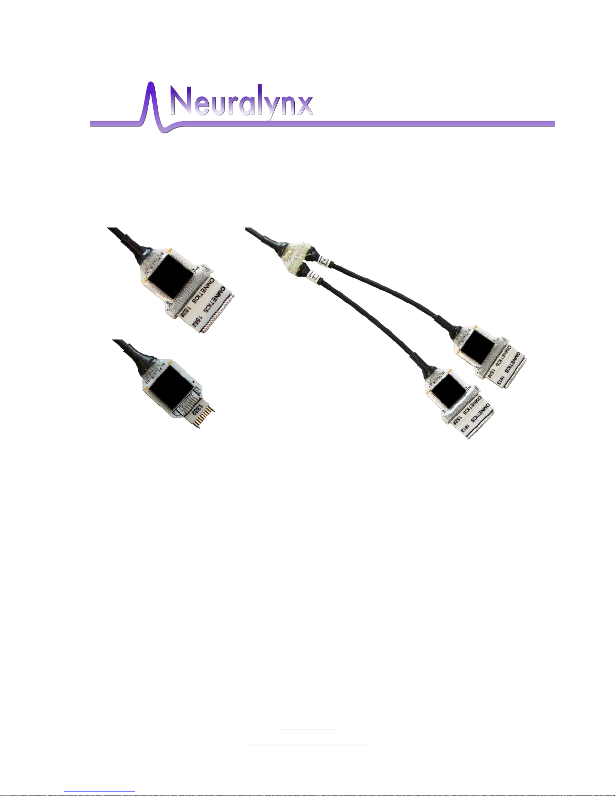
HS-xx-mux
User’s Manual
Multiplexing Headstage that allows recording on 16 to 64
individual electrodes
Neuralynx, Inc.
105 Commercial Drive, Bozeman, MT 59715
Phone 406.585.4542 • Fax 866.585.1743
Neuralynx.com
Revision 1.3 [email protected]
6/29/2017
Page 2

Table of Contents
1 Document Overview ................................................................................................... 4
2 Multiplexing Headstage Overview ............................................................................. 4
2.1 Important Note ..................................................................................................... 4
3 What's included with the multiplexing headstage? ..................................................... 5
3.1 HS-64-mux ........................................................................................................... 5
3.2 HS-32-mux ........................................................................................................... 5
3.3 HS-16-mux ........................................................................................................... 5
3.4 TETH-mux headstage .......................................................................................... 6
3.5 ADPT-DUAL-HS-MUX ...................................................................................... 6
3.6 Additional Testing Items ...................................................................................... 6
3.6.1 SM-32/64 ...................................................................................................... 6
3.6.2 HS-36 Impedance Plug ................................................................................. 7
3.6.3 HS-16-mux Impedance Plug ......................................................................... 7
3.6.4 HS-16-mux Video Tracking LEDs ............................................................... 7
3.7 Electrostatic Sensitive Equipment ........................................................................ 7
4 Quick Start .................................................................................................................. 8
4.1 Multiplexing Headstage Setup ............................................................................. 8
4.2 Start Cheetah ........................................................................................................ 9
4.2.1 Configure Cheetah with the Proper Configuration ....................................... 9
4.3 Drive Signal into the Multiplexing Headstage ................................................... 10
4.4 Performing an Impedance Test .......................................................................... 13
5 Hardware Overview .................................................................................................. 17
5.1 Multiplexing Headstage Amplifier and A/D Converter ..................................... 17
5.2 Multiplexing Headstage Communication........................................................... 17
5.3 Input Connectors ................................................................................................ 17
5.4 HS-36 Impedance Plug Resistance Values ........................................................ 21
5.5 HS-16 Impedance Plug Resistance Values ........................................................ 22
6 Multiplexing Headstage Command Descriptions ..................................................... 23
7 Glossary .................................................................................................................... 27
List of Figures and Ta ble s
Figure 3-1 HS-64-mux ........................................................................................................ 5
Figure 3-2 HS-32-mux ........................................................................................................ 5
Figure 3-3 HS-16-mux ........................................................................................................ 5
Figure 3-4 TETH-mux headstage ....................................................................................... 6
Figure 3-5 ADPT-DUAL-HS-MUX ................................................................................... 6
Figure 3-6 SM-64 ................................................................................................................ 6
Figure 3-7 HS-36 Impedance Plug ..................................................................................... 7
Figure 3-8 HS-16-mux Impedance Plug ............................................................................. 7
Figure 3-9 HS-16-mux Video Tracking LEDs ................................................................... 7
Figure 4-1 Hardware Connections ...................................................................................... 8
Figure 4-2 Multiplexing Headstage Starting AD Channel ................................................. 9
Figure 4-3 Bank 1, 2, 3 and 4 Switches Up. Reference Switch Down. ............................ 10
Figure 4-4 Bank 2, 3 and 4 Switches Up. Bank 1 and Reference Switches Down........... 11
Figure 4-5 Bank 3 and 4 Switches Up. Bank 1, 2 and Reference Switches Down........... 11
Revision 1.3 HS-xx mux User’s Manual
6/29/2017 Page 2
Page 3

Figure 4-6 Bank 4 Switches Up. Bank 1, 2, 3 and Reference Switches Down. ............... 12
Figure 4-7 All Switches Down (1000µV). ........................................................................ 12
Figure 4-8 All Switches Down (25µV). ............................................................................ 13
Figure 4-9 All Switches Up (25µV). ................................................................................ 13
Figure 4-10 Example Configuration File .......................................................................... 14
Figure 4-11 AC Current Waveform on Channel 25.......................................................... 15
Figure 4-12 Channel Electrode Impedance Calculation ................................................... 15
Figure 4-13 Example Configuration File .......................................................................... 16
Figure 5-1 Multiplexing Headstage Hardware Illustration ............................................... 17
Figure 5-2 HS-16-mux headstage Input Pinout ................................................................ 18
Figure 5-3 Example HS-16-mux Channel Mapping Configuration File .......................... 19
Figure 5-4 HS-32-mux headstage Input Pinout ................................................................ 20
Figure 5-5 HS-64-mux Input Pinout(1) ........................................................................... 21
Figure 5-6 HS-64-mux Input Pinout(2) ............................................................................ 21
Figure 5-7 HS-36 Impedance Plug Test Value ................................................................. 22
Figure 5-8 HS-16 Impedance Plug Test Value ................................................................. 22
Figure 6-1 DHSTriggerFastSettle Command Syntax ....................................................... 23
Figure 6-2 DHSSetImpedanceMeasureEnabled Command Syntax ................................. 24
Figure 6-3 DHSSetImpedanceMeasureCurrent Command Syntax .................................. 25
Figure 6-4 DHSSetImpedanceMeasureCurrent Command Syntax .................................. 26
Revision 1.3 HS-xx mux User’s Manual
6/29/2017 Page 3
Page 4

1 Document Overview
This document describes the specifications and features of the multiplexing headstage. It
also explains how to set up your headstage, test it, and use it during normal operation.
There is a glossary at the end of the document.
2 Multiplexing Headstage Overview
This HS-xx-mux is a multiplexing headstage that records from up to 64 individual
electrodes. The physiological signals are digitized at the headstage, which allows the
required number of cable conductors to be greatly reduced.
Features:
• Versions include the HS-16-mux, the HS-32-mux and the HS-64-mux.
• ±5mV Input Range.
• >80dB Common Mode Rejection Ratio(CMRR) at 60Hz.
• <2.5µV
• Interfaces directly with Digital Lynx SX.
• 12 Conductor Cable transfers up to 64 channels to Digital Lynx SX.
• Up to 128 Digital Channels per Digital Lynx SX.
• Compatible with Neuralynx EIBs.
Noise (0.1Hz to 9kHz).
RMS
2.1 Important Note
The multiplexing headstage must be connected to the Digital Lynx SX before the system
is powered ON. Otherwise, the system won’t recognize that a multiplexing headstage is
present.
Revision 1.3 HS-xx mux User’s Manual
6/29/2017 Page 4
Page 5
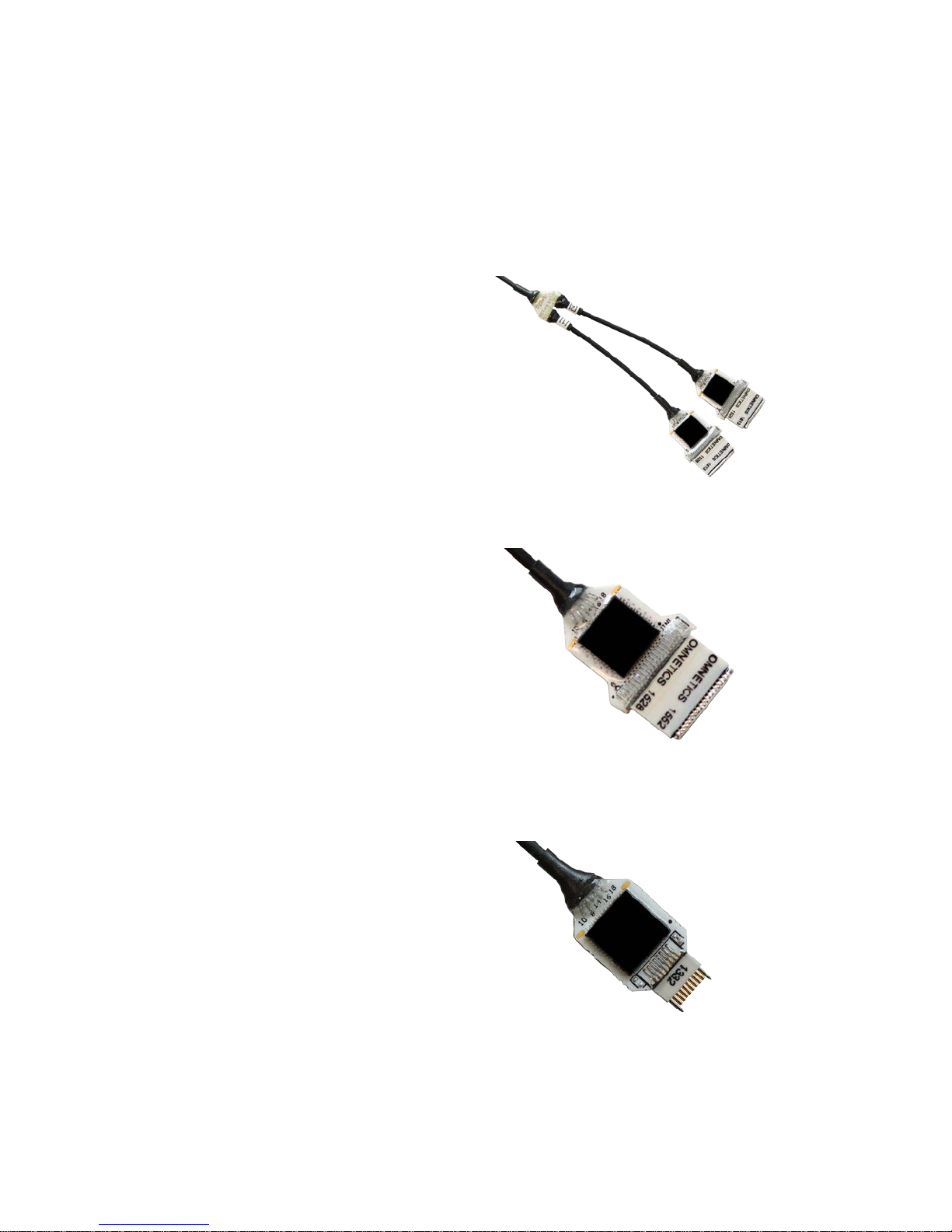
• 64 Channels digitized on the
Figure 3-1 HS-64-mux
• 32 Channels digitized on the
Figure 3-2 HS-32-mux
• 16 Channels digitized on the
3 What's included with the multiplexing headstage?
There are three different channel counts available as a multiplexing headstage, the HS16-mux, the HS-32-mux and the HS-64-mux. Both arrive already soldered to the tether,
with the TETH-multiplexing headstage as an extension.
3.1 HS-64-mux
headstage.
• 2 Static References, one per
bank of 32 channels.
• Available with 44 Pin
Omnetics Connectors or 36 Pin
Omnetics Connectors.
• Available in 1 meter, 2 meter,
and 3 meter options.
•
4.5 grams.
3.2 HS-32-mux
headstage.
• 1 Static Reference for all 32
channels.
• Available with 44 Pin
Omnetics Connector or 36 Pin
Omnetics Connector.
• Available in 1 meter, 2 meter,
and 3 meter options.
•
2.0 grams.
3.3 HS-16-mux
headstage.
• 1 Static Reference for all 16
channels.
• Compatible with HS-16 and HS-18
Series EIBs.
• Standard 2 meter tether.
• 1.3 grams
• Can be ordered with or without
video tracking LED ears.
Figure 3-3 HS-16-mux
Revision 1.3 HS-xx mux User’s Manual
6/29/2017 Page 5
Page 6
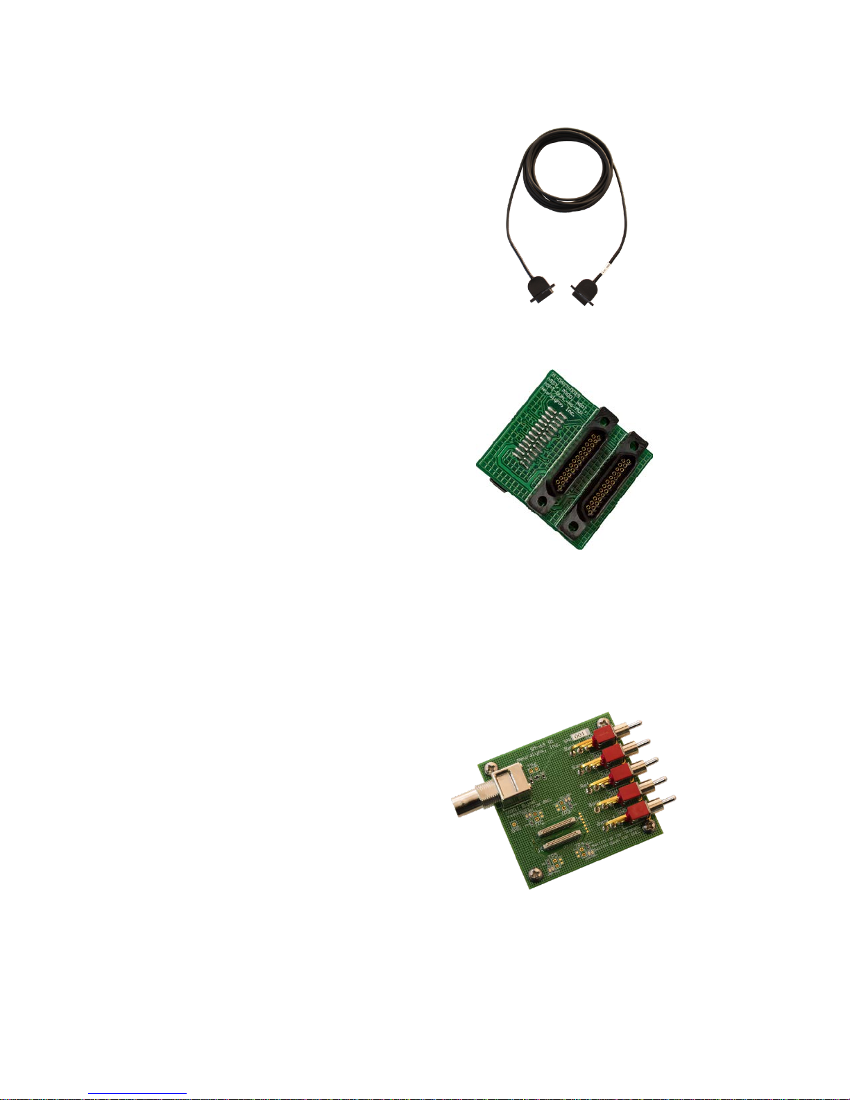
• Compatible with any multiplexing
Figure 3-4 TETH-mux headstage
• Allows two HS-32-mux or two HS-
Figure 3-5 ADPT-DUAL-HS-MUX
• Interface for driving test
Figure 3-6 SM-64
3.4 TETH-mux headstage
headstage.
• Standard 1.5 meter tether.
3.5 ADPT-DUAL-HS-MUX
16-mux to connect to a single port
on the Digital Lynx SX.
3.6 Additional Testing I tems
Additionally, a Signal Mouse and an Impedance Plug can be purchased as separate items
for testing the signal through the multiplexing headstage and the Digital Lynx SX.
3.6.1 SM-32/64
signals into the multiplexing
headstage.
• Switches control Bank 1, Bank
2, Bank 3, Bank 4 and the
Reference.
Revision 1.3 HS-xx mux User’s Manual
6/29/2017 Page 6
Page 7
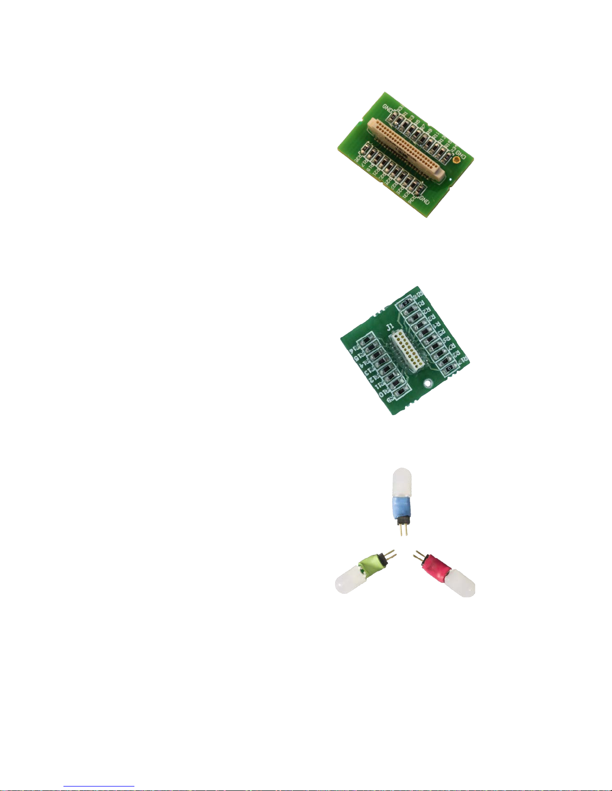
• Test plug with different
• Test plug with different
• Omni-directional Video
3.6.2 HS-36 Impedance Plug
resistance values on each bank
of eight channels.
3.6.3 HS-16-mux Impedance Plug
resistance values on each bank
of four channels.
Figure 3-7 HS-36 Impedance Plug
Figure 3-8 HS-16-mux Impedance Plug
3.6.4 HS-16-mux Video Tracking LEDs
Tracking LEDs.
• Color Options: Red, Blue, and
Green.
3.7 Electrostatic Sensitive Equipment
All Neuralynx Equipment is Electrostatic Sensitive and should be handled with
appropriate measures. Always wear a static strap and use all appropriate ESD measures
when handling any electronics. Please contact Neuralynx for detailed information if you
have questions.
Revision 1.3 HS-xx mux User’s Manual
6/29/2017 Page 7
Figure 3-9 HS-16-mux Video Tracking LEDs
Page 8
4 Quick Start
The following instructions are provided to quickly set up and test your multiplexing
headstage setup. If your Digital Lynx SX system requires the upgrade for compatibility
with the multiplexing headstage, please see the Digital Lynx SX HS Multiplexer Upgrade
User Manual.
4.1 Multiplexing Headstage S e t up
The multiplexing headstage connects to the Digital Lynx SX in a different way than a
standard Neuralynx Analog Headstage. Instead of connecting to a DRS-36 Board or an
Input Board, the multiplexing headstage connects to the Digital Lynx SX Motherboard.
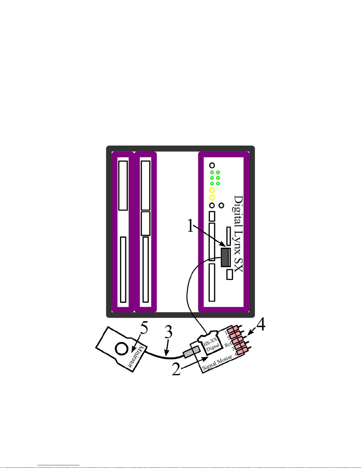
The multiplexing headstage connections are illustrated and described below.
Connections:
1. Connect the multiplexing headstage to the connector labeled 1 on the Digital
Lynx SX Motherboard.
Revision 1.3 HS-xx mux User’s Manual
6/29/2017 Page 8
Figure 4-1 Hardware Connections
Page 9

Number of Input
Boards
HS-64 Digital Starting AD
Channel
Total Channel
Count
a. NOTE: The multiplexing headstage must be connected to the Digital Lynx
SX before the system is powered ON. Otherwise the system won’t
recognize that a multiplexing headstage is present.
2. Connect the multiplexing headstage to the SM-64.
3. Connect the Minirator, or other signal source to the SM-64 using a BNC Cable.
4. Turn the Bank 1, 2, 3, and 4 switches on the SM-64to the Signal Position (Up).
Turn the Reference switch on the SM-64 to the Ground Position (Down).
5. Set the Minirator, or other signal source to output a 1VPP Sine Wave at 100 Hz.
The SM-64 will reduce this signal to roughly to 1mVPP.
6. Power the Digital Lynx SX ON.
4.2 Start Cheetah
In Digital Lynx SX Systems that already contain Input Boards, it is important to note that
the AD Channels associated with the multiplexing headstage begin after the last Input
Board AD Channel. This concept is illustrated in the table below. This table assumes one
multiplexing headstage is being used. The maximum channel count of the Digital Lynx
SX System is 512 Channels
0 0 64
1 32 96
2 64 128
3 96 160
4 128 192
5 160 224
6 192 256
7 224 288
8 256 320
9 288 352
10 320 384
11 352 416
12 384 448
13 416 480
14 448 512
Figure 4-2 Multiplexing Headstage Starting AD Channel
4.2.1 Configure Cheetah with the Proper Configuration
Power On the Digital Lynx SX and wait for boot cycle to complete. On the Computer
open the Cheetah Configuration Folder. Modify your preferred Configuration File to
allow the multiplexing headstage AD Channels to be sent to Cheetah. On the Desktop
select the Run Cheetah shortcut to open the Cheetah Welcome Screen. Boot Cheetah with
a modified configuration file for your new setup. In this example 32 CSCs are used.
Revision 1.3 HS-xx mux User’s Manual
6/29/2017 Page 9
Page 10
4.3 Drive Signal into the Multiplexing Headstage
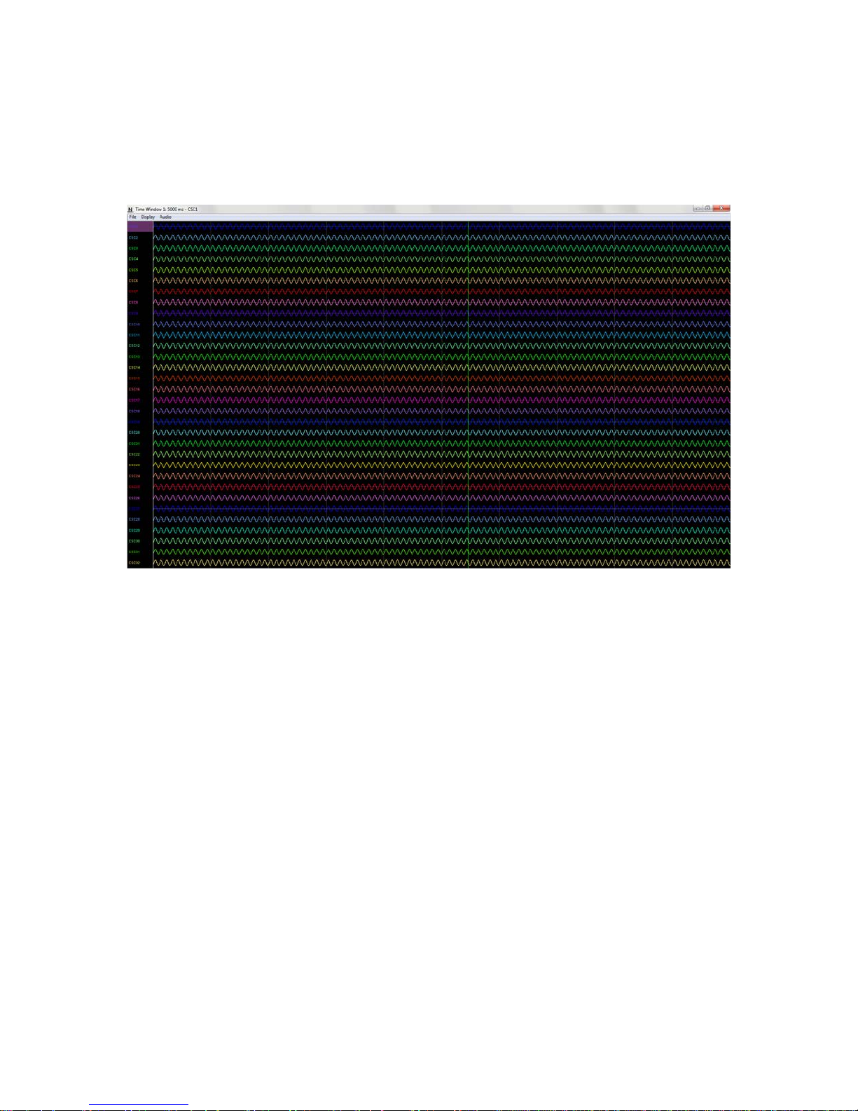
In Cheetah, select the ACQ Button to Start Acquisition. Set the Input Range for all 32
CSCs to 1000µV and set the Reference for all 32 CSCs to Reference 1. Observe the 32
CSCs. Each should show a reduced (roughly 1mVPP) version of the Minirator output.
Refer to the figure below.
Figure 4-3 Bank 1, 2, 3 and 4 Switches Up. Reference Switch Down.
Switch the Bank 1 Switch to the Ground Position (Down). Observe the 32 CSCs. CSCs
1-8 should now be flatlined while CSCs 9-32 still shows a reduced (roughly 1mVPP)
version of the Minirator output. Refer to the figure below.
Revision 1.3 HS-xx mux User’s Manual
6/29/2017 Page 10
Page 11
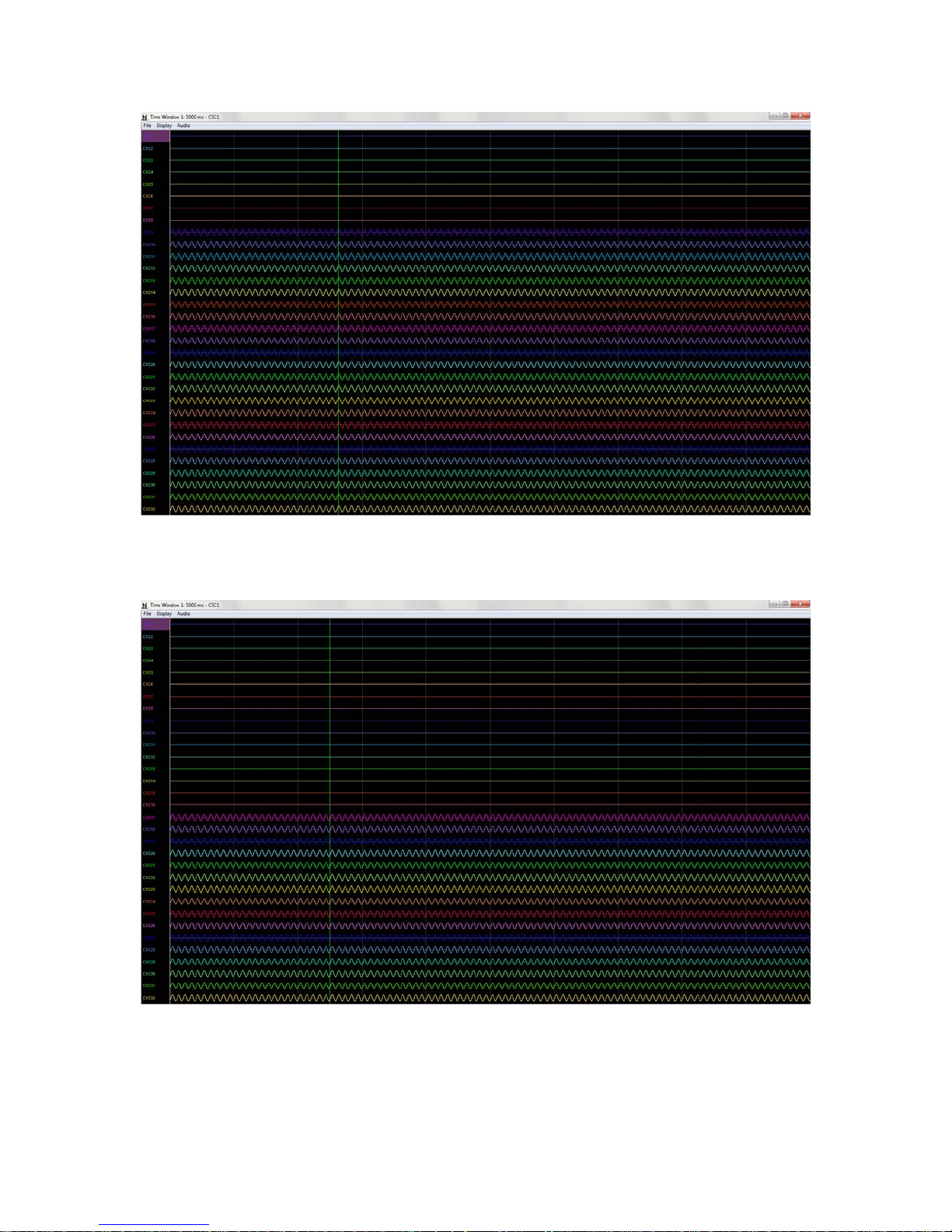
Figure 4-4 Bank 2, 3 and 4 Switches Up. Bank 1 and Reference Switches Down.
Switch the Bank 2 Switch to the Ground Position (Down). Observe the 32 CSCs. CSCs
1-16 should now be flatlined while CSCs 17-32 still show a reduced (roughly 1mVPP)
version of the Minirator output. Refer to the figure below.
Figure 4-5 Bank 3 and 4 Switches Up. Bank 1, 2 and Reference Switches Down.
Switch the Bank 3 Switch to the Ground Position (Down). Observe the 32 CSCs. CSCs
1-24 should now be flatlined while CSCs 25-32 still show a reduced (roughly 1mVPP)
version of the Minirator output. Refer to the figure below.
Revision 1.3 HS-xx mux User’s Manual
6/29/2017 Page 11
Page 12
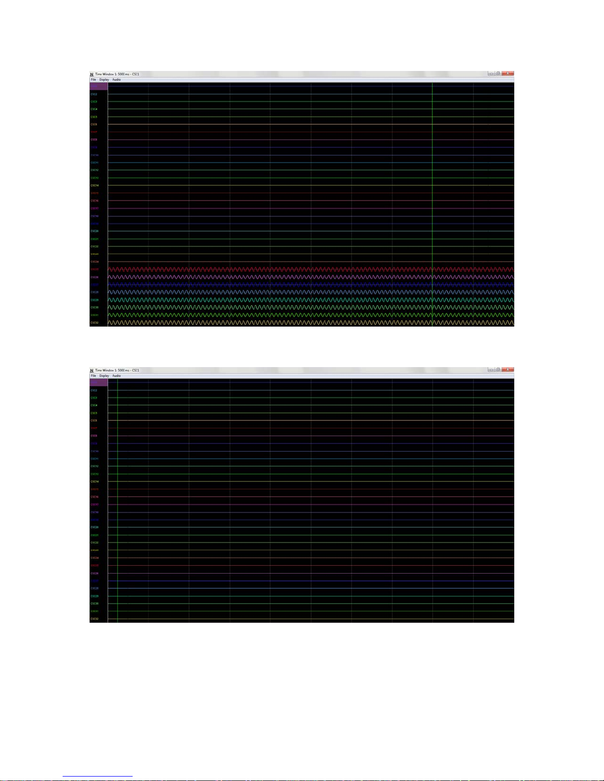
Figure 4-6 Bank 4 Switches Up. Bank 1, 2, 3 and Reference Switches Down.
Switch the Bank 4 Switch to the Ground Position (Down). Observe the 32 CSCs. CSCs
1-32 should now be flatlined. Refer to the figure below.
Figure 4-7 All Switches Down (1000µV).
Set the Input Range for all 32 CSCs to 25µV. Observe the 32 CSCs. CSCs 1-32 now
show the baseline noise. Each should be less than 25µVpp and void of any repetitive
signals. Refer to the figure below.
Revision 1.3 HS-xx mux User’s Manual
6/29/2017 Page 12
Page 13
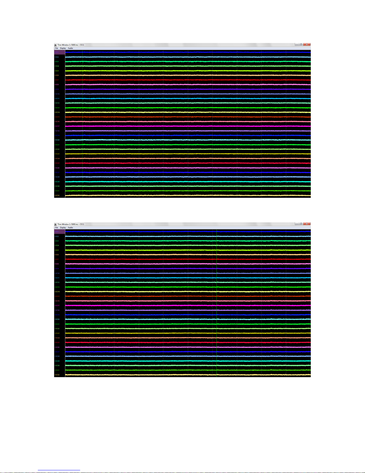
Figure 4-8 All Switches Down (25µV).
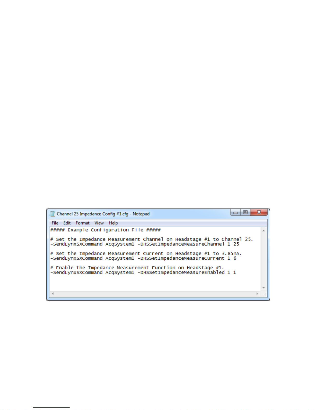
Switch all the Switches to the Signal Position (Up). Observe the 32 CSCs. Each should
be less than 25µVpp and void of any repetitive signals. Refer to the figure below.
4.4 Performing an Impedance Test
The multiplexing headstage contains an internal AC current waveform generator that can
output 9 different current amplitudes at 1kHz. The AC current waveform generator is
controlled by sending specific commands to the Digital Lynx SX, which are then routed
Revision 1.3 HS-xx mux User’s Manual
6/29/2017 Page 13
Figure 4-9 All Switches Up (25µV).
Page 14
to the multiplexing headstage. These commands can be sent through a NetCom interface
or simply through a Cheetah Configuration File. All Multiplexing Headstage Commands
and their syntax are discussed in Section 6 Multiplexing Headstage Command
Descriptions. To begin the multiplexing headstage needs to be connected to the HS-36
Impedance Plug.
Connections:
1. Disconnect the multiplexing headstage from the SM-64.
2. Connect the multiplexing headstage to the HS-36 Impedance Plug.
In this example we will use a Cheetah Configuration File to perform an impedance test
on Channel 25 of a multiplexing headstage using the following sequence of events (this
assumes all the hardware is still connected as shown in Section 4.1 Multiplexing
Headstage Setup):
Command Sequence:
1. Set the Impedance Measurement Channel to 25.
2. Set the Impedance Measurement Current to 3.85nA (The Current Options for this
command are listed in Section 6 Multiplexing Headstage Command
Descriptions, 3.85nA is option number 6).
3. Enable the Impedance Measurement Function.
Using the commands and syntax discussed in Section 6 Multiplexing Headstage
Command Descriptions the following configuration file can be created.
Figure 4-10 Example Configuration File
Once the configuration file has been created and saved it can be run in Cheetah by
selecting File > Open Configuration File. Browse to the configuration file selected Open.
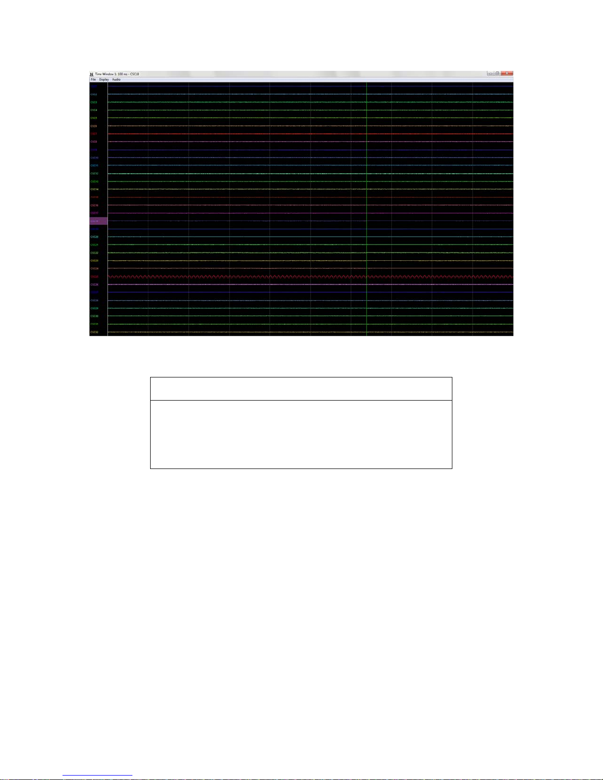
The configuration file will immediately execute. Observe CSC 25 in Cheetah, it should
show a 1000Hz sine wave roughly 750mVPP. Refer to the figure below.
Revision 1.3 HS-xx mux User’s Manual
6/29/2017 Page 14
Page 15
Z = V / I
Z – Impedance of Electrode in Ω
Generator (Convert to Amps)
Figure 4-11 AC Current Waveform on Channel 25
The channels electrode impedance at 1kHz can be approximately calculated using the
following equation.
V – Voltage Amplitude Measured in Cheetah (Convert to
Volts)
I – Current Amplitude output of the AC Current Waveform
Figure 4-12 Channel Electrode Impedance Calculation
Once the impedance testing is complete the Impedance Measurement Function should be
disabled. Once again this can be done with a Cheetah Configuration File.
Command Sequence:
1. Disable the Imped ance M easur emen t Fun cti on .
Using the commands and syntax discussed in Section 6 Multiplexing Headstage
Command Descriptions the following configuration file can be created.
Revision 1.3 HS-xx mux User’s Manual
6/29/2017 Page 15
Page 16
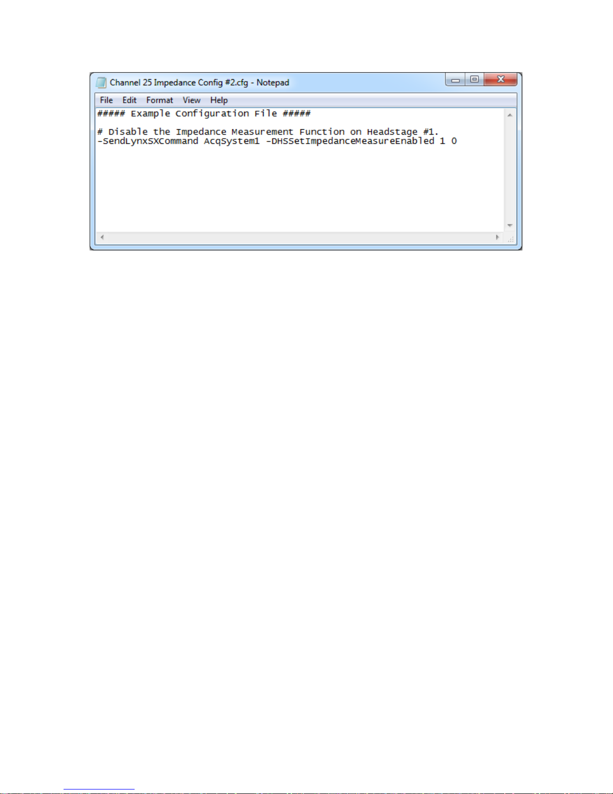
Figure 4-13 Example Configuration File
Revision 1.3 HS-xx mux User’s Manual
6/29/2017 Page 16
Page 17
5 Hardware Overview
5.1 Multiplexing Headstage Am plifier and A/D Converter
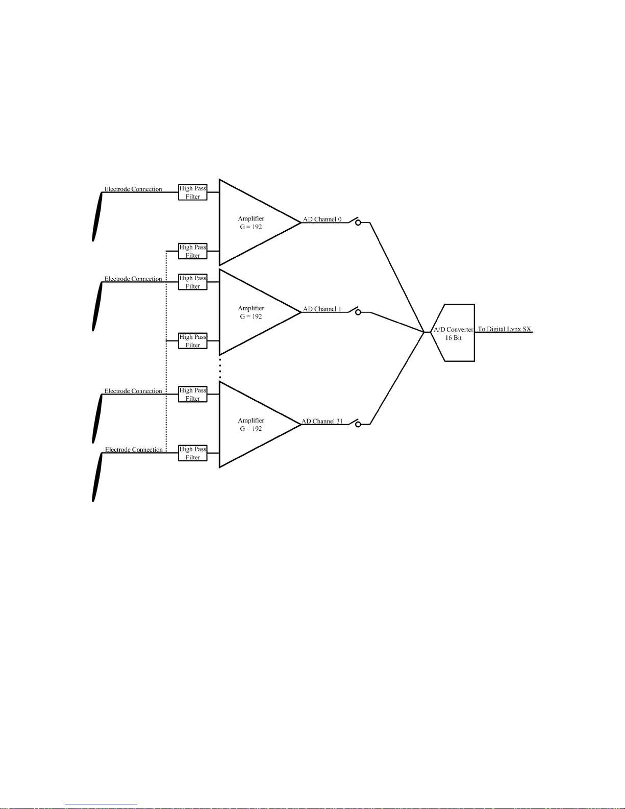
Each AD Channel is digitized on the multiplexing headstage using a fixed reference. The
channels are AC Coupled and the gain is fixed at 192 [V/V]. One 16 Bit A/D Converter
digitizes 32 AD Channels. This concept is illustrated in the figure below.
Figure 5-1 Multiplexing Headstage Hardware Illustration
5.2 Multiplexing Headstage Com m unication
The multiplexing headstage communicates with the Digital Lynx SX via a dedicated SPI
Bus. Digital signals transfer data between the multiplexing headstage and the Digital
Lynx SX. Digital signal quality degrades as cable length increases. For this reason it is
recommended that the total cable length of the multiplexing headstage not exceed 4
meters.
5.3 Input Connectors
The pinouts for the multiplexing headstages are shown in the figures below.
Revision 1.3 HS-xx mux User’s Manual
6/29/2017 Page 17
Page 18
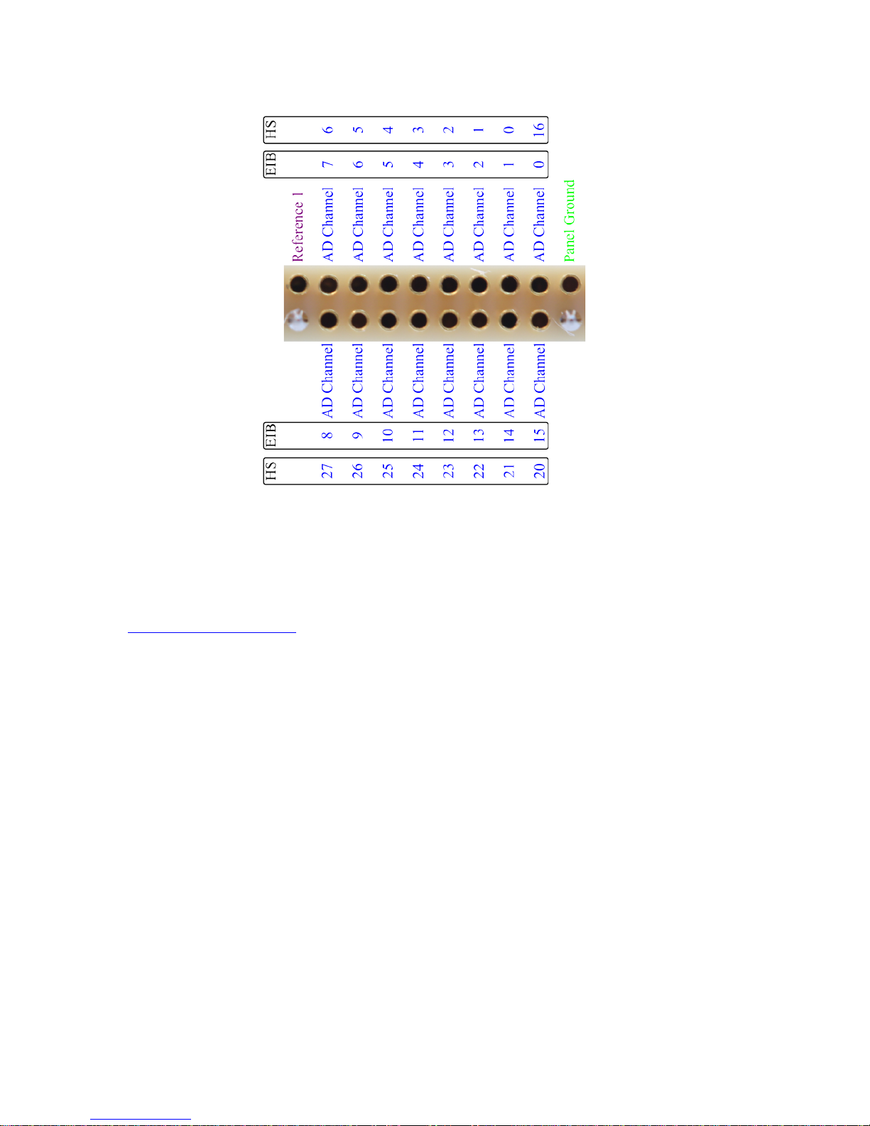
18 Pin Female Nano Omnetics Connector
Figure 5-2 HS-16-mux headstage Input Pinout
Note: The HS-16-mux AD Channels do not match with the EIB AD Channels. A custom
Cheetah Configuration File is required to properly map the AD Channels. An example
configure file can be downloaded from neuralynx.com or the following outlined can be
used. For further help with creating your own setup configuration files, please contact
Revision 1.3 HS-xx mux User’s Manual
6/29/2017 Page 18
Page 19
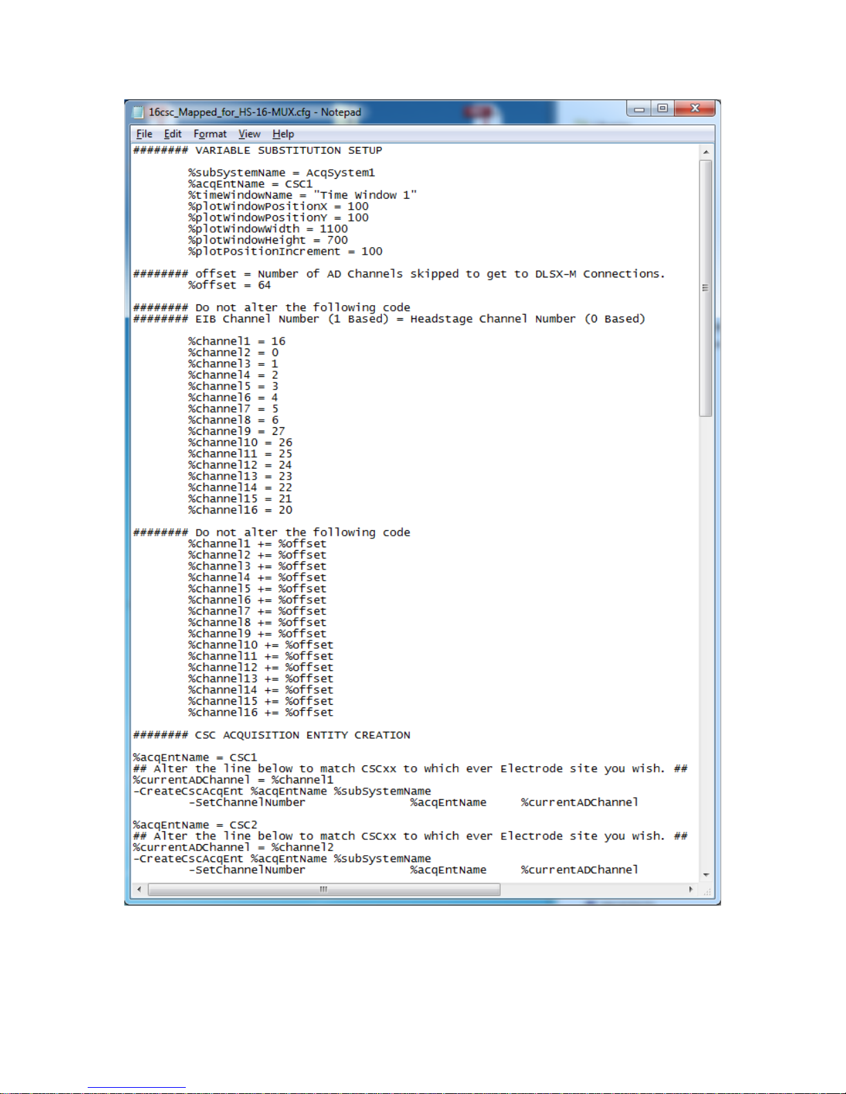
Figure 5-3 Example HS-16-mux Channel Mapping Configuration File
Revision 1.3 HS-xx mux User’s Manual
6/29/2017 Page 19
Page 20
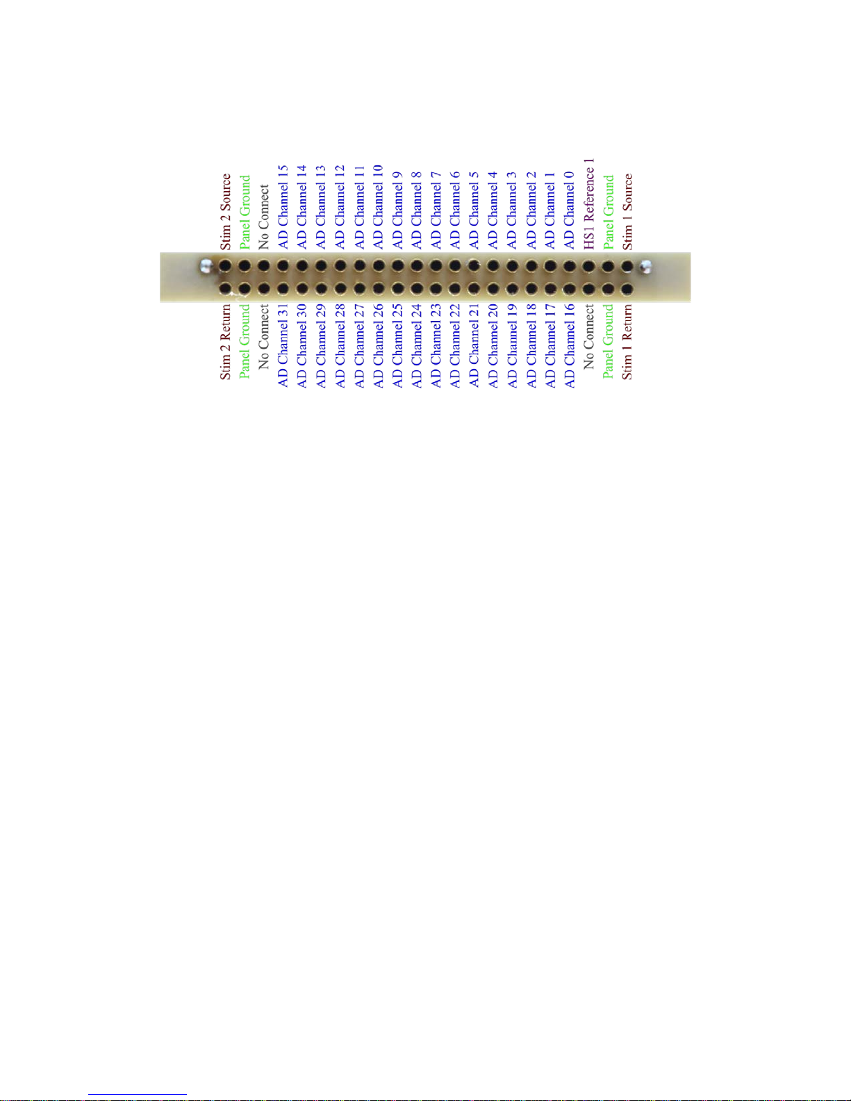
44 Pin Female Nano Omnetics Connector
Figure 5-4 HS-32-mux headstage Input Pinout
Revision 1.3 HS-xx mux User’s Manual
6/29/2017 Page 20
Page 21
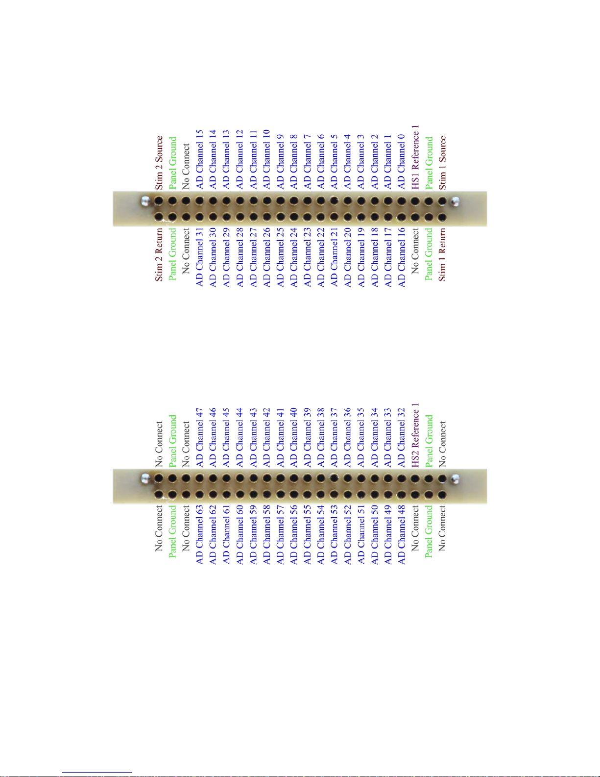
44 Pin Female Nano Omnetics Connector
Figure 5-5 HS-64-mux Input Pinout(1)
44 Pin Female Nano Omnetics Connector
Figure 5-6 HS-64-mux Input Pinout(2)
5.4 HS-36 Impedance Plug Resistance Values
The following figure contains the resistance values of each channel on the HS-36
Impedance Plug.
Revision 1.3 HS-xx mux User’s Manual
6/29/2017 Page 21
Page 22
Channel
Resistance
Channel
Resistance
Reference 1
0Ω
Reference 2
0Ω
Channel 1
1MΩ
Channel 17
250kΩ
Channel 2
1MΩ
Channel 18
250kΩ
Channel 3
1MΩ
Channel 19
250kΩ
Channel 4
1MΩ
Channel 20
250kΩ
Channel 5
1MΩ
Channel 21
250kΩ
Channel 6
1MΩ
Channel 22
250kΩ
Channel 7
1MΩ
Channel 23
250kΩ
Channel 8
1MΩ
Channel 24
250kΩ
Channel 9
500kΩ
Channel 25
100kΩ
Channel 11
500kΩ
Channel 27
100kΩ
Channel 12
500kΩ
Channel 28
100kΩ
Channel 13
500kΩ
Channel 29
100kΩ
Channel 14
500kΩ
Channel 30
100kΩ
Channel 15
500kΩ
Channel 31
100kΩ
Channel 16
500kΩ
Channel 32
100kΩ
Reference 3
0Ω
Reference 4
0Ω
Channel
Resistance
Reference 1
0Ω
Channel 2
1MΩ
Channel 3
1MΩ
Channel 4
1MΩ
Channel 5
500kΩ
Channel 6
500kΩ
Channel 7
500kΩ
Channel 8
500kΩ
Channel 9
250kΩ
Channel 10
250kΩ
Channel 11
250kΩ
Channel 12
250kΩ
Channel 13
100kΩ
Channel 14
100kΩ
Channel 15
100kΩ
Channel 16
100kΩ
Channel 10 500kΩ Channel 26 100kΩ
Figure 5-7 HS-36 Impedance Plug Test Value
5.5 HS-16 Impedance Plug Resistance Values
The following figure contains the resistance values of each channel on the HS-16
Impedance Plug.
Channel 1 1MΩ
Figure 5-8 HS-16 Impedance Plug Test Value
Revision 1.3 HS-xx mux User’s Manual
6/29/2017 Page 22
Page 23
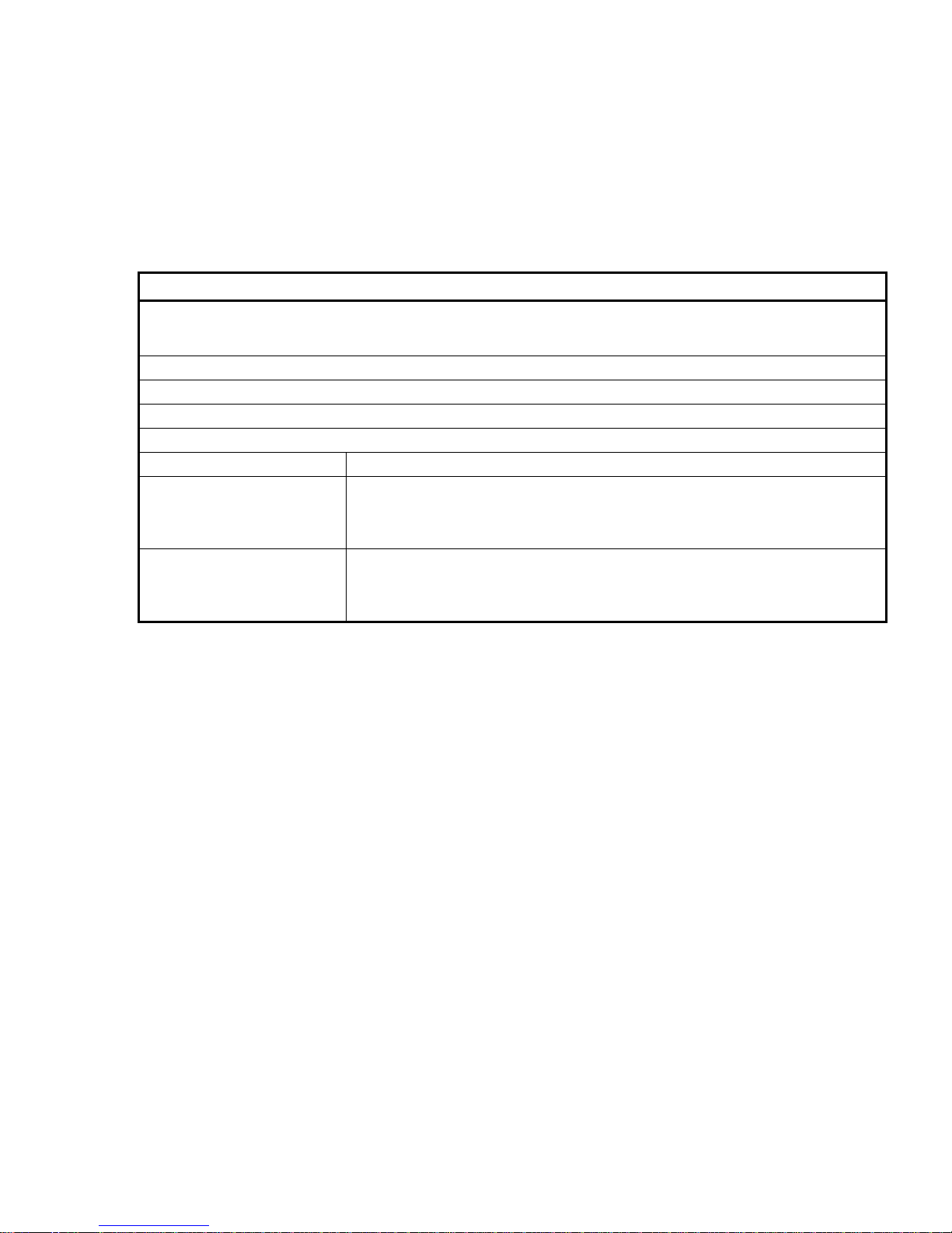
Triggers the Fast Settle Function. The Fast Settle Function can be used to reset the headstage when large input
elapsed the Fast Settle Function is turned off.
Default: This command is an action, there is no default value.
Arguments:
This value can be one of the follo wing keywords:
All: Selects all multiplexing hea dstages as the command target.
This value can be one of the follo wing keywords:
All: Selects all Banks as the command target.
6 Multiplexing Headstage Command Descriptions
Commands can be sent to the multiplexing headstage through NetCom to configure
certain settings on the headstage. These include; Impedance Functions and Fast Settle
Functions. The following figures detail each command, how it is used, and its defaults. It
is not necessary that these be used at any time.
-SendLynxSXComman d <Hardware Sub Syst em Name> -DHSTriggerFastSettle <Headstage> <Bank>
signals have caused amplifier saturation. The Fast Settle Function is approximately 300µs. Once this time has
Example: -Se nd L yn xSX Command AcqS yste m1 –DHSTriggerFastSettle 2 1
Usage: This Command can be used any time after acquisition has been started.
Hardware Subsystem Name Name of sub system which will be c ontrolled.
Headstage
Bank
1: Selects multiplexing headstage 1 as the command target.
2: Selects multiplexing headstage 2 as the command target.
1: Selects Bank 1 (first 32 channels) as the command target.
2: Selects Bank 2 (second 32 channels) as the command target.
Figure 6-1 DHSTriggerFastSettle Command Syntax
Revision 1.3 HS-xx mux User’s Manual
6/29/2017 Page 23
Page 24
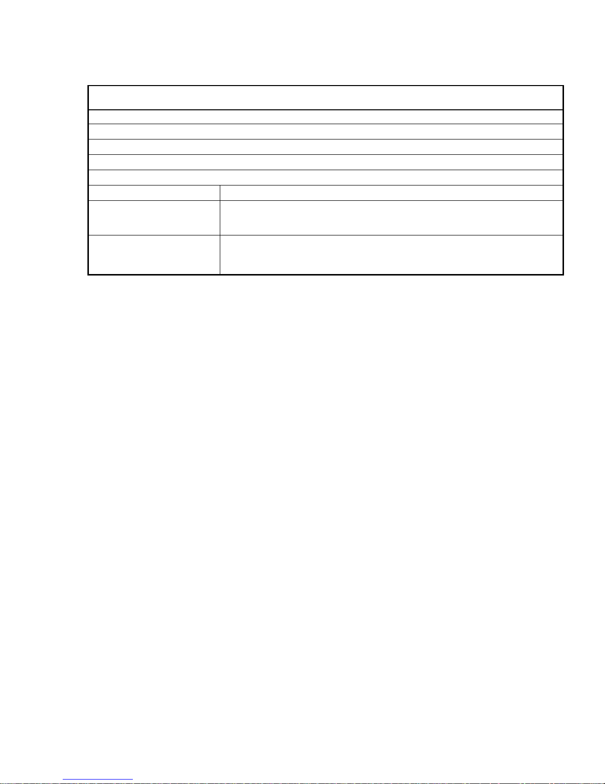
-SendLynxSXComman d <Hardware Sub System Name> -DHSSetImpe dance M ea sureEna bled <He adst ag e>
<Value>
Enables or disables the internal Electrode Impedance Measurement Circuitry on the HS-XX Digital.
Example:
Default: The internal Electrode Impedance Measurement Circuitry is by default disabled.
Usage:
Arguments:
This value can be one of the follo wing keywords:
2: Selects multiplexing headstage 2 as the command target.
-SendLynxSXCommand Acq S yst e m1 –DHSSetImpedanceMeasureEnabled 2 1
This Command can be used after the Digital Lynx SX Hardware Sub System has been created.
Hardware Subsystem Name Name of sub system that will be co ntrolled.
Headstage
Value
1: Selects multiplexing headstage 1 as the command target.
This value can be one of the follo wing keywords:
1: Enables the internal Electrode Impedance Measurement Circuitry.
0: Disables the internal Electrode Impedance Measurement Circuitry.
Figure 6-2 DHSSetImpedanceMeasureEnabled Command Syntax
Revision 1.3 HS-xx mux User’s Manual
6/29/2017 Page 24
Page 25
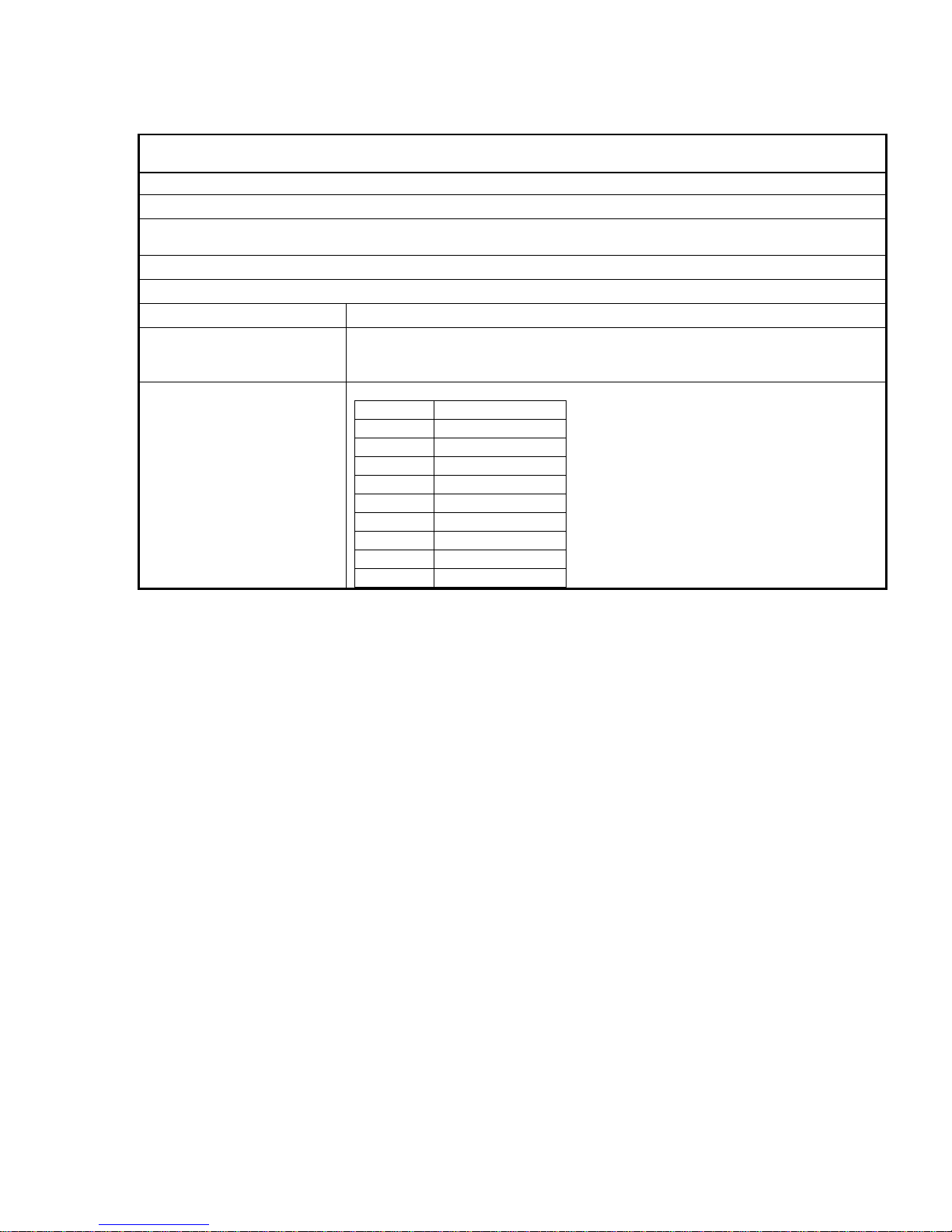
-SendLynxSXComman d <Hardware Sub System Name> -DHSSetImpedanceMeasureCurrent <Headstage>
<Value>
Sets the current that the multiplexing headstage will use for its internal Electrode Impedance Measurement Circuitry.
Example:
Default: The Impedance Measurement Current Value is by default set to 1, but the internal Electrode Impedance
Measurement Circuitry is by default d isa bled.
Usage:
Arguments:
This value can be one of the follo wing keywords:
2: Selects multiplexing headstage 2 as the command target.
This value can be one of the follo wing keywords:
Value
Current
1 0.128
nA 2 0.257
nA 3 0.385
nA 4 1.28
nA 5 2.57
nA 6 3.85
nA 7 12.8
nA 8 25.7
nA 9 38.5
nA
-SendLynxSXCommand Acq S yst e m1 –DHSSetImpedanceMeasureCurrent 2 3
This Command can be used after the Digital Lynx SX Hardware Sub System has been created.
Hardware Subsystem Name Name of sub system that will be co ntrolled.
Headstage
Value
1: Selects multiplexing headstage 1 as the command target.
Figure 6-3 DHSSetImpedanceMeasureCurrent Command Syntax
Revision 1.3 HS-xx mux User’s Manual
6/29/2017 Page 25
Page 26

-SendLynxSXComman d <Hardware Sub Syst em Name> -DHSSetImpedanceMeasureChannel <Headstage>
<Value>
Sets the channel that the multiplexing headstage will connect to its internal Electrode Impedance Measurement
Circuitry.
Example: -Se nd L yn xSX Command AcqS yste m1 –DHSSetImpedanceMeasureCurrent 2 38
Default: The Impedance Measurement Channel is by default set to 1, but the internal Electrode Impedance
Measurement Circuitry is by default d isa bled.
Usage: This Command can be used after the Digital Lynx SX Hardware Sub System has been created.
Arguments:
Hardware Subsystem Name
Name of sub system that will be co ntrolled.
This value can be one of the follo wing keywords:
2: Selects multiplexing headstage 2 as the command target.
Headstage
Value
1: Selects multiplexing headstage 1 as the command target.
This value can be one of the follo wing keywords:
1-64
Figure 6-4 DHSSetImpedanceMeasureCurrent Command Syntax
Revision 1.3 HS-xx mux User’s Manual
6/29/2017 Page 26
Page 27

7 Glossary
CSC – Neuralynx acronym for Continuously Sampled Channel.
EIB – Neuralynx acronym for Electrode Interface Board.
Multiplexing Headstage (mux)– Headstage that digitized the physiological
signals at the headstage. XX denotes the number of
channels (ie. HS-32-mux digitizes 32 physiological
signals).
Revision 1.3 HS-xx mux User’s Manual
6/29/2017 Page 27
 Loading...