

Page 1

Product Information
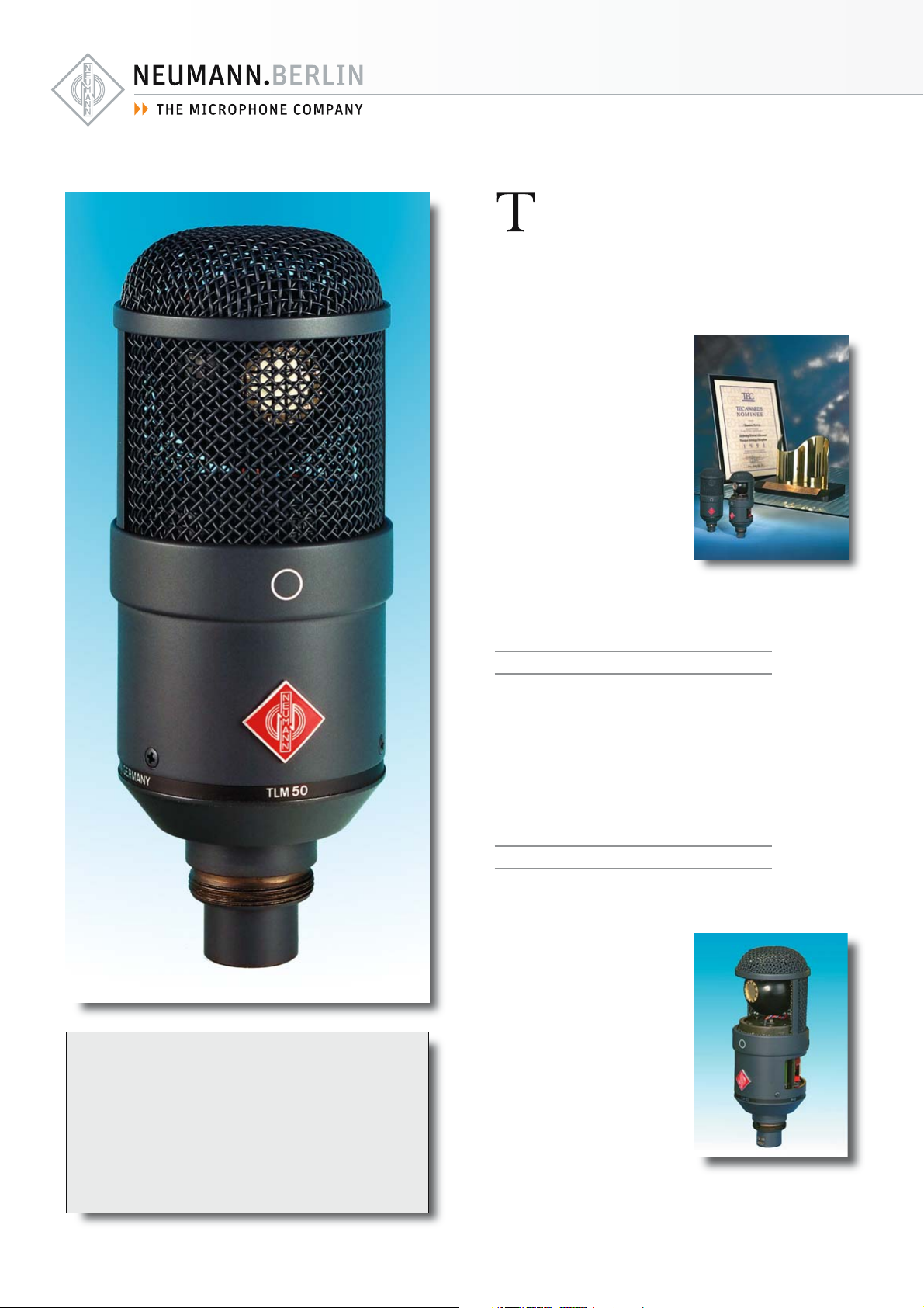
TLM 50
Pressure
Microphone
www.neumann.com
Georg Neumann GmbH • Ollenhauerstr. 98 • 13403 Berlin • Germany • Tel.: +49 (30) 41 77 24-0 • Fax: +49 (30) 41 77 24-50
E-Mail: headoffice@neumann.com, engineering@neumann.com, catalog-info@neumann.com • Web: www.neumann.com
Page 2
he TLM 50 is a studio microphone with
an unusual omnidirectional characteristic. The
same way as in the legendary M 50, the capsule is mounted flush into the surface of a
sphere.
This unique design gives the
microphone a smooth rise in
frequency response and an
increased directivity in the
upper frequency range.
There the directional characteristic is almost comparable
to a pressure gradient microphone. In the lower audio
spectrum it performs more as
a pressure transducer with a
linear response down to the
lowest frequencies.
In 1991 the TLM 50 received
the MIX MAGAZINE TECAward. It is supplied with a swivel mount cable and an auditorium hanger.
Applications
Features
• Small diaphragm microphone
with omnidirectional pattern
• Successor of the world-wide
successful M 50
• Excellent response down to
lowest frequencies
• Pressure transducer
• High frequency polar pattern
similar to pressure gradient
transducer
• Set includes cable and
auditorium hanger
The design of the TLM 50 is based on the legendary M 50 and has very unique acoustic features. It provides a tool for capturing both direct sound from the instruments and a bal-anced
image of the reverberant environment and is
therefore especially suited for stereo recordings with two main microphones.
Acoustic features
The diaphragm of the pressure capsule is
12 mm in diameter and is only 5 µm thick. As
a result it has a remarkably fast
transient response. The diaphragm is made out of titanium, manufactured by Neumann in a proprietary electroplating process.
The headgrille is acoustically
very transparent. Even extreme
sound pressure levels do not at
all affect the trans-ducer’s response.
Of course, the headgrille also
protects the microphone capsule from mechanical shock
and serves as wind and pop screen.
Page 3

TLM 50
Electrical features
The letters TLM stand for “transformerless microphone”. The usual output transformer is replaced in the TLM 50 by an electronic circuit.
As with traditional transformers, this technique
ensures good common mode rejection, and prevents RF interference, that may influence the
balanced audio signal. The transformerless microphone amplifier provides low self noise, fast
transient response, and high output capability.
To protect the capsule from hum pickup
through the gauze mesh, it is designed as an
“active capsule”: The capsule housing contains
the impedance converter built as a hybrid
module. The resulting audio signal is fed with
low impedance to the filter and output stage
in the housing.
Filter and attenuation
A –10 dB switch and a high-pass filter for the
attenuation of frequencies below 100 Hz are
located at the rear of the microphone. In the
position LIN, the cutoff frequency is 30 Hz. Its purpose
is to protect the following
equipment from subsonic interference (for example strong
air currents).
The –10 dB function is achieved by reducing the capsule polarizing voltage from 60 V to
23 V. It helps to avoid overloading the following units during very high sound pressure levels.
The switch does not extend the dynamic
range of the microphone amplifier, but shifts
it upward by 10 dB.
Application Hints
• Its special acoustic properties make this an
ideal mic for most classical recordings
• A superb AB stereo pair for perfect balance
of direct and reverberant sound
• Decca tree, setup with three microphones
• A highest quality spot (solo) mic
These are just some of the most common
applications. We recommend additional
experimentation to gain maximum use from
this microphone.
Cable suspension
The recommended accessories, such as cables
and connectors, provide sufficient stability and
therefor allow suspending the TLM 50 eg.
from the ceiling of a concert hall with the included MNV 87 auditorium hanger freely from
its own cable.
Delivery Range
TLM 50 Microphone
IC 4 mt Microphone cable (with stand mount swivel)
MNV 87 mt Auditorium hanger
Dust cover
Wooden box
Catalog No.
TLM 50 Se t ................................................. blk ....... 007135
Selection of Accessories
Battery supply, BS 48 i ........................blk ....... 006494
Power supply, N 248 EU .................. blk ....... 008537
Power supply, N 248 US ................... blk ....... 008538
Power supply, N 248 UK .................. blk ....... 008539
Elastic suspension, EA 50 ................. blk ....... 007359
Windscreen, WS 87 ............................... blk ....... 006753
A complete survey and detailed descriptions
of all accessories are contained in the
accessories catalog.
Meaning of color codes:
blk = black
ni = nickel
Page 4

measured in free-field conditions (IEC 60268-4), tolerance ±2 dB
Technical Data
Acoustical operating principle ............................................... Pressure transducer
Directional pattern ................................................................................. Omnidirectional
Frequency range .................................................................................... 20 Hz...20 kHz
Sensitivity at 1 kHz into 1 kohm ............................................................. 20 mV/Pa
Rated impedance ................................................................................................... 50 ohms
Rated load impedance ................................................................................ 1000 ohms
Signal-to-noise ratio, CCIR1) (rel. 94 dB SPL) ............................................ 68 dB
Signal-to-noise ratio, A-weighted1) (rel. 94 dB SPL) ............................. 81 dB
Equivalent noise level, CCIR1)............................................................................... 26 dB
Equivalent noise level, A-weighted1)........................................................... 13 dB-A
1)
according to IEC 60268-1; CCIR-weighting acccording to CCIR 468-3, quasi peak; A-weighting according to IEC 61672-1, RMS 2) measured as equivalent el. input signal
Errors excepted, subject to changes • Printed in Germany • Publ. 01/08 058155/A04
Neumann is a registered trademark of the Georg Neumann GmbH in certain countries.
®
Maximum SPL for THD 0.5%2)...................................................................... 136 dB
Maximum SPL for THD 0.5% with preattanuation2)....................... 146 dB
Maximum output voltage ..................................................................................... 1 0 d Bu
Dynamic range of the microphone amplifier (A-weighted) .......... 12 3 d B
Supply voltage (P48, IEC 61938) ........................................................ 48 V ± 4 V
Current consumption (P48, IEC 61938) ........................................................3 mA
Matching connector ................................................................................................... XLR3F
Weight .................................................................................................................................490 g
Diameter .......................................................................................................................... 5 6 mm
Length............................................................................................................................ 145 mm
 Loading...