

Page 1

Product Information
M 149 Tube
Tube Microphone
www.neumann.com
Georg Neumann GmbH • Ollenhauerstr. 98 • 13403 Berlin • Germany • Tel.: +49 (30) 41 77 24-0 • Fax: +49 (30) 41 77 24-50
E-Mail: headoffice@neumann.com, engineering@neumann.com, catalog-info@neumann.com • Web: www.neumann.com
Page 2
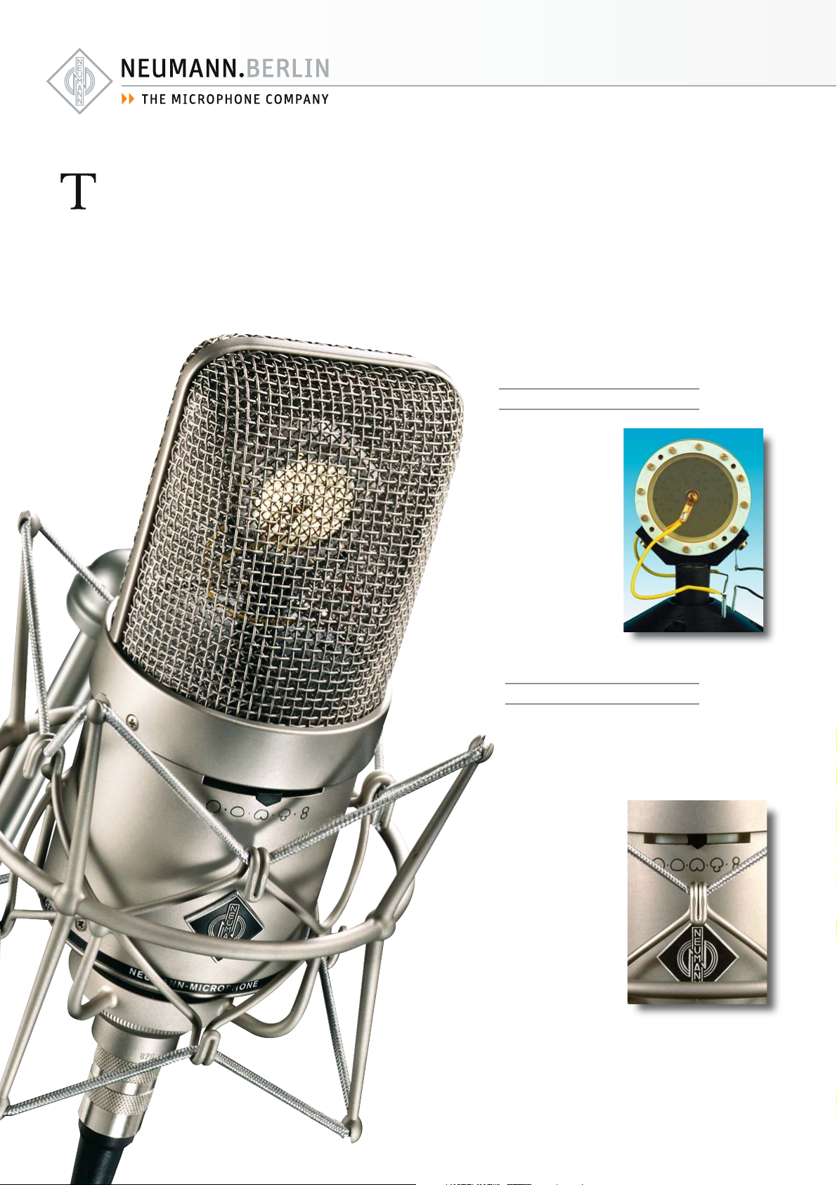
he M 149 Tube is a variable dual-diaphragm microphone. The K 49 capsule – wellknown from the legendary U 47 and M 49
microphones – is followed by a tube func-tioning as an impedance converter. In contrast to
earlier concepts – utilizing a transformer – the
tube is complemented with a transformerless
output circuit
design.
The M 149 Tube can thus feed long microphone cables without any coloration.
Two slide switches are located below the
large, acoustically very open headgrille.
The switch at the front allows selection one
of nine directional patterns. The slide switch
at the rear operates a seven-step high pass
filter. It allows a very fine adjustment of the
cut-off frequency.
Applications
There are nine polar
patterns to choose
from, making this mi-
crophone an ideal
choice for a wide range
of recording situations.
As its ancestors, the
M 149 Tube is a superb
vocalist microphone, not
only because of the cap-
sule, but also due to its
modern circuitry, character-
ized by extremely low noise
level.
Acoustic features
the polar patterns.
The capsule is mount-
ed elastically inside the
headgrille to eliminate
structure borne noise. The
surface below the capsule is
shaped like a cone to disperse
any reflected sound from the
acoustic upper half space.
This avoids any interference
with the primary sound arriving at the capsule directly.
A large headgrille surrounds
the capsule. It is acoustically
very open and therefore increases the sonic realism.
The design of the microphone
is a registered design of
the Georg Neumann GmbH
in certain countries.
The M 149 Tube is addressed
from the front, marked with the
Neumann logo. Also on the front
is the switch for the selection of
Page 3

Polar patterns
The polar pattern switch selects one of nine
directional patterns: omnidirectional, wide-angle-cardioid, cardioid, hypercardioid, figure-8,
and one additional intermediate pattern between each major position.
Electrical features
The circuit of the M 149 Tube microphone
has been developed to exceed traditional designs. We have selected a modern tube (triode) and combined its exceptional transmission
characteristics with the advantages of our proven transformerless output circuit. The aim was
to provide a more controlled environment for
the audio signal on its path from the capsule
to the output section.
M 149 Tube
The final stage is an integrated amplifier, especially designed for such applications. It features
very low distortion (THD < 0.002 % at ± 10 V),
very low self-noise, and high output current
capability. As a result, the tube circuit is completely decoupled from the microphone output and its characteristic response curve will
be unaffected by very high signal levels or varying load conditions.
The lower output impedance and higher output current capability allow cable lengths up
to 300 m (1000 feet) without any degradation
of the audio signal.
The tube amplifier changes the high impedance
of the capsule and adds 10 dB of gain to the
audio signal, providing optimum operating spec-
Technical Data
Acoustical operating principle .......................... Pressure gradient transducer
Directional pattern .................................. Omnidirectional, wide angle cardioid,
cardioid, hypercardioid, figure-8
plus one intermediate position each
Frequency range .................................................................................... 20 Hz...20 kHz
Sensitivity at 1 kHz into 1 kohm .......................................... 34/47/62 mV/Pa
Rated impedance ................................................................................................... 50 ohms
Rated load impedance ................................................................................. 1000 ohms
Signal-to-noise ratio, CCIR2) (rel. 94 dB SPL) .......................... 66/69/71 dB
Signal-to-noise ratio, A-weighted2) (rel. 94 dB SPL) ............ 78/81/83 dB
Equivalent noise level, CCIR2)............................................................. 28/25/23 dB
Equivalent noise level, A-weighted2)......................................... 16/13/11 dB-A
Typical SPL (tube characteristic)3):
for < 0,5% THD ...................................................................................................... 12 0 d B
for < 5% THD ............................................................................................................. 1 36 dB
Maximum output voltage ..................................................................................... 1 8 d Bu
Dynamic range of the microphone amplifier cardioid:
1)
(A-weighted) for < 0,5% THD (for < 5% THD) ................... 101 (121) dB
Powering....................................................................................... Power supply N 149 A
Microphone matching connectors ..................................................................... DIN8F
1)
Power supply matching connectors .................................................................. XLR3F
1)
Weight.................................................................................................................................. 730 g
1)
Diameter ........................................................................................................................... 70 mm
1)
Length............................................................................................................................. 2 0 1mm
1)
Omnidirectional / cardioid / figure-8 2) according to IEC 60268-1; CCIR-weighting acccording to CCIR 468-3, quasi peak; A-weighting according to IEC 61672-1, RMS 3) measured as equivalent el. input signal
Page 4

ifications. The wide dynamic range is impressive, as peak output can be ±10 V, at 20 mA.
The ideal operating point of the tube is maintained throughout its entire life expectancy.
Plate current and filament voltage are constantly
regulated. A sensor circuit monitors and compensates for any voltage drop across the microphone cable. The tube is heated up slowly
through inverse current limiting to guarantee
long life. Optimum operating conditions are
reached within a very short time.
Filter
A seven-position slide switch is located on the
back of the microphone. It selects a high-pass
filter, advancing in half-octave steps between
20 Hz and 160 Hz (–3dB).
This filter is useful to suppress rumble from air-conditioning and in windy situations.
In addition, the filter provides
an effective tool to control the
audio signal when the microphone is used at
close distance and therefore proximity effect
alters the program material.
Delivery Range
M 149 Tube Microphone
N 149 A Power supply unit with power cable,
EA 170 Elastic suspension,
KT 8 Microphone cable,
Aluminium case,
Dust cover
Catalog No.
M 149 Tube (230 V, EU) ................... ni ......... 008390
M 149 Tube (117 V, US) ................... ni ......... 008399
M 149 Tube (230 V, UK) ................... ni ......... 008403
Selection of Accessories
Auditorium hanger, MNV 87 ...........ni .......... 006804
Auditorium hanger, MNV 87 mt ... blk ....... 006806
Table stand, MF 3 ...................................blk ....... 007321
Table stand, MF 4 ...................................blk ....... 007337
Stand extension, STV 4 ........................ blk ....... 006190
Stand extension, STV 20 ..................... blk ....... 006187
Stand extension, STV 40 ..................... blk ....... 006188
Stand extension, STV 60 ..................... blk ....... 006189
Popscreen, PS 15 ..................................... blk ....... 008472
Popscreen, PS 20 a ................................ blk ....... 008488
Microphone cable, IC 3 mt ................ blk ....... 006543
Adapter cable AC 25 ............................ blk ....... 006600
Delivery Range
The specifically designed
new N 149 A power supply
unit feeds the M 149 Tube
through an 8-core cable. The
output connector for the audio signal is a 3-pin XLR. The
output signal is balanced.
The microphone comes as a
set in a high-quality aluminum case, together
with the 8-core microphone connecting cable,
the N 149 A power supply with plug-in mains
unit, the EA 170 full elastic microphone suspension and a dust cover.
Features
• Switchable tube microphone
• Transformerless circuitry
• High output level
• Pressure gradient transducer
with the M 49 capsule
• Acoustically very open wire
mesh cage
• Nine directional characteristics: omni, wide angle
cardioid, cardioid, hypercardioid, figure-8, and one
intermediate position each
• 7fold switchable low
frequency roll-off
A complete survey and detailed descriptions of all
accessories are contained in the accessories
catalog.
Meaning of color codes:
blk = black
ni = nickel
Application Hints
• Universal tube mic
• Its warm and yet transparent sound gives
volume and presence to a vocalist
• A wide range of adjustments provide the most
subtle differentiation of sound, especially in the
range of proximity effect
• Mic for broadcasting, dubbing, and voice-over
• Spot mic for close miking of solo instruments,
especially strings, wind instruments, and piano
These are just some of the most common
applications. We recommend additional experimentation to gain maximum use from this
microphone.
Page 5

measured in free-field conditions (IEC 60268-4), tolerance ±2 dB
M 149 Tube
Page 6

Errors excepted, subject to changes • Printed in Germany • Publ. 01/08 058150/A05
Neumann is a registered trademark of the Georg Neumann GmbH in certain countries.
®
 Loading...