

Page 1

Product Information
GFM 132
Boundary Layer
Microphone
www.neumann.com
Georg Neumann GmbH, Berlin • Ollenhauerstr. 98 • 13403 Berlin • Germany • Tel.: +49 (30) 417724-0 • Fax: +49 (30) 417724-50
E-Mail: headoffice@neumann.com, engineering@neumann.com, catalog-info@neumann.com • Web: www.neumann.com
Page 2
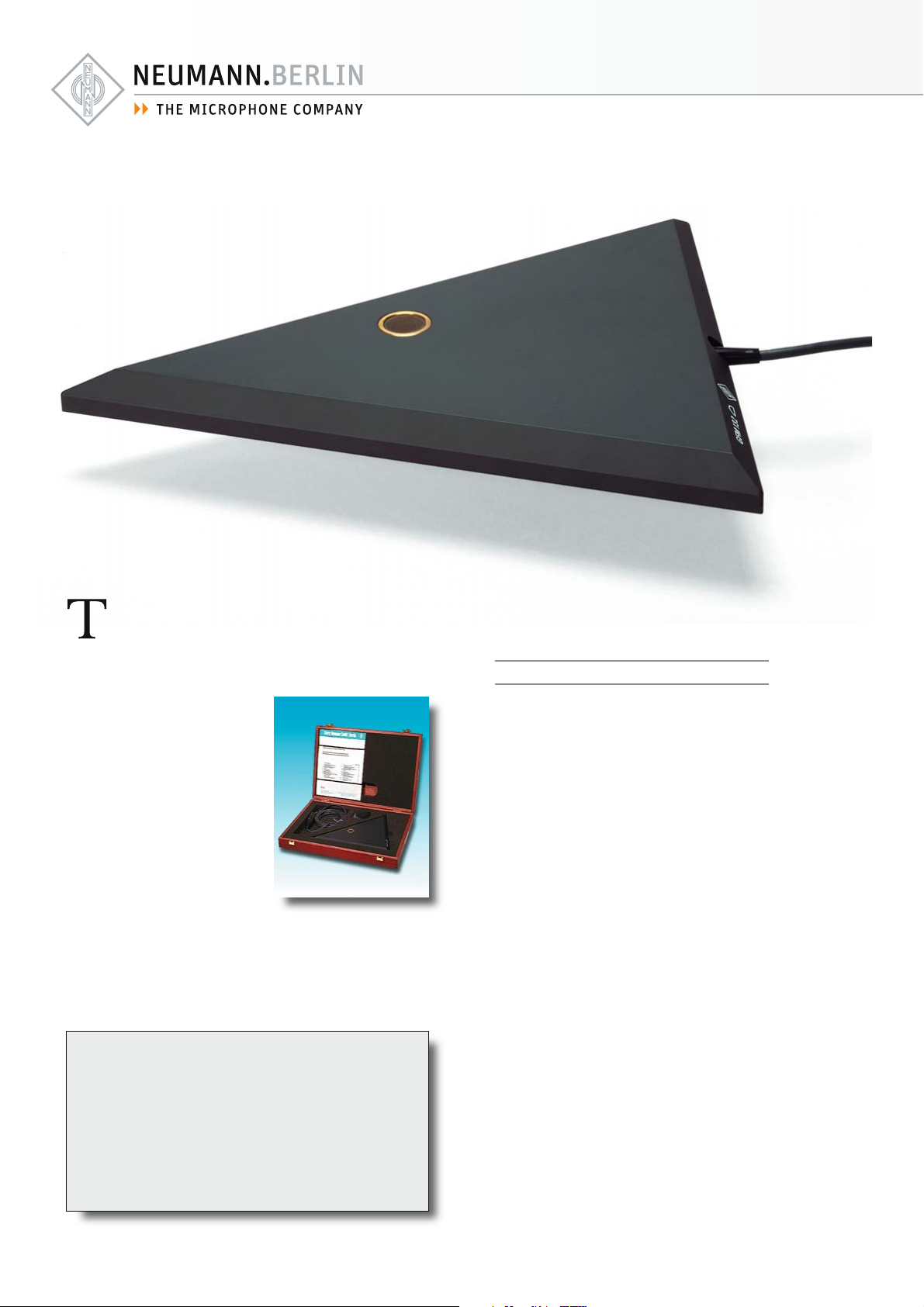
he GFM 132 is a boundary layer microphone. Through computer simulation Neumann optimized the design to be free of any
comb filter effects due to reflections, typical of other such microphones.
The smooth frequency response for all angles of incidence exhibits a rise in the upper frequency range. This assures that
all sound sources, even distant
ones, will be recorded with clarity and presence.
Therefore, typical applications
are for live recordings, such as
in the orchestra pit of opera
houses, theaters, and on stage.
The back of the microphone has non-slip pads
for its use in a horizontal or inclined position, and holes for wall suspension. It is supplied with a wooden case and a wind screen.
Features
• Boundary layer microphone
• Pressure transducer
• Frequency independent
hemispherical directional
characteristic
• Identical diffuse- and
free-field response
• No angle dependent
coloration through patented
triangular form
• No comb filter effects
• Insensitive to structure-borne
noise
Background
Boundary-layer microphones are generally characterized by the following features:
They have an identical flat frequency response
in the diffuse-field and free-field;
They have a hemispherical polar pattern, independent of the frequency;
They have a 6 dB higher output level through
pressure doubling at the boundary surface.
Until recently, neither the potential of identical diffuse- and free-field response, nor the
ideal hemispherical polar patterns throughout
the entire frequency range have been achieved
by any known boundary-layer microphone. Circular, square, or rectangular plates were used
to mount the acoustic transducer and to provide the “live” sound reflecting surface for
pressure doubling at high frequencies.
However, such shapes have disadvantages:
The sound pressure level at the position of
the transducer depends on the frequency and
the incidence angle. The incoming primary
sound field is superimposed upon the secondary sound field resulting from diffraction at the
edges of the plate. As a result, boundary-layer
microphones using circular, square or rectangular shaped plates generate linear distortion,
such as comb filter effects, of frequency and
polar response.
Page 3

GFM 132
The Neumann solution
The GFM 132 boundary-layer microphone has
a unique, computer generated shape that totally avoids these disadvantages. The path
lengths from each edge point to the center of
the transducer are distributed evenly for all
wavelengths within the frequency range.
This design eliminates any possible linear distortion of frequencies caused at the location
of the electro-acoustic transducer by the interaction of the
incoming primary sound field
with the secondary sound field
from diffraction at the edges of
the plate.
The operating range of the plate reaches from
the lowest frequency causing a pressure doubling in front of the plate to the upper limit of
the audible range.
The microphone features a smooth frequency
response for all angles of incidence, with a slight
rise in amplitude in the upper frequency range.
This assures that all sound sources, even distant ones, will be recorded with clarity and presence.
Acoustic features
• The microphone provides high output voltage through pressure doubling at the
boundary surface.
• The microphone reproduces with great accuracy very low frequencies if the
boundary layer is adequately large.
• In surroundings with good acoustics the
GFM 132 creates incredibly realistic
AB-stereo recordings, taking advantage
of delay and intensity differences in the
audio signal.
Electrical features
The GFM 132 uses transformerless circuitry
and operates on 48 V phantom power. The
usual output transformer is replaced by an electronic circuit.
As with traditional transformers, this design ensures good common mode rejection and prevents RF interference that may influence the
balanced audio signal. The microphone features
high output capability and extremely low self
noise. It provides exceptionally clean sound reproduction free of coloration.
Attenuation
The microphone has a 10 dB
attenuation switch to prevent
the input of the following unit
from being overloaded.
The switch is located next to
the cable connector at the side
of the GFM 132 boundary layer microphone.
• Identical diffuse- and free-field frequency
response. Its advantage is that the apparent
tonal balance of a moving sound source is
independent of the distance and direction.
• The special geometric shape prevents angle-dependent coloration in the vertical and
horizontal planes.
• There are no comb filter effects in typical
applications, for example on a speaker's
desk, as they would occur through reflections, using conventional microphones.
• The hemispherical polar pattern is independent of the frequency, producing
a spatial sound with presence and excellent transparency.
• As is common for a pressure transducer,
the microphone is insensitive to structure
borne noise and air movements.
Application Hints
• An ideal stereo pair for AB technique
• For round table discussions
• Quick and easy installation for the “fast interview”
• Invisible spot mic for
- harp,
- cello,
- double bass,
- acoustic guitar
• Excellent bass response when used as main mic
for drums
These are just some of the most common
applications. We recommend additional experimentation to gain maximum use from this microphone.
Page 4

Delivery Range
Microphone GFM 132
Plug-on Windscreen
Microphone cable
Wooden box
Catalog No.
GF M 13 2 ......................................................blk ....... 007100
Selection of Accessories
Battery supply, BS 48 i ........................ blk ....... 006494
Power supply, N 248 EU .................. blk ....... 008537
Power supply, N 248 US ................... blk ....... 008538
Power supply, N 248 UK .................. blk ....... 008539
Microphone cable, IC 3 mt ................ blk ....... 006543
A complete survey and detailed descriptions of all
accessories are contained in the accessories catalog.
Meaning of color codes:
blk = black, ni = nickel
measured in free-field conditions (IEC 60268-4), tolerance ±2 dB
Technical Data
Acoustical operating principle ................................................ Pressure transducer
Directional pattern .................................................................................... Hemispherical
Frequency range ..................................................................................... 2 0 Hz...20 kHz
Sensitivity at 1 kHz into 1 kohm .............................................................. 18 mV/Pa
Rated impedance .................................................................................................... 50 ohms
Rated load impedance ................................................................................. 1000 ohms
Signal-to-noise ratio, CCIR1) (rel. 94 dB SPL) ............................................. 70 dB
Signal-to-noise ratio, A-weighted1) (rel. 94 dB SPL) .............................. 80 dB
Equivalent noise level, CCIR1)................................................................................ 24 dB
Equivalent noise level, A-weighted1)............................................................ 14 dB-A
1)
according to IEC 60268-1; CCIR-weighting acccording to CCIR 468-3, quasi peak; A-weighting according to IEC 61672-1, RMS 2) measured as equivalent el. input signal
Errors excepted, subject to changes • Printed in Germany • Publ. 01/08 058156/A03
Neumann is a registered trademark of the Georg Neumann GmbH in certain countries.
®
Maximum SPL for THD 0.5%2)........................................................................ 137 dB
Maximum SPL for THD 0.5% with preattanuation2)......................... 147 dB
Maximum output voltage ...................................................................................... 10 dBu
Dynamic range of the microphone amplifier (A-weighted) ............ 123 dB
Supply voltage (P48, IEC 61938) ......................................................... 48 V ± 4 V
Current consumption (P48, IEC 61938) ......................................................... 2 mA
Matching connector ..................................................................................................... XLR3F
Weight .................................................................................................................................. 46 0 g
Width ................................................................................................................................ 213 mm
Depth ...............................................................................................................................168 mm
 Loading...