

Page 1
DMI-
B
O M
Registrieren Sie bitte Ihr
System auf der Website
www.my-Solution-D.com,
um über Updates informiert
zu werden!
Please register your system
on the website
www.my-Solution-D.com,
to be informed whenever updates
are available!
· . · ·
() / - · - · @. · ..
Page 2

1. Einleitung
In dieser Anleitung fi nden Sie alle wichtigen Informationen für den Betrieb und die Pfl ege des
von Ihnen erworbenen Produktes. Lesen Sie diese
Anleitung bitte sorgfältig und vollständig, bevor
Sie das Gerät benutzen. Bewahren Sie die Anleitung bitte so auf, dass sie für alle momentanen
und späteren Nutzer jederzeit zugänglich ist.
Weitergehende Informationen, insbesondere
auch zu den verfügbaren Zubehörteilen und den
Neumann-Servicepartnern, fi nden Sie auf unserer
Website www.neumann.com. Die Servicepartner
können Sie auch telefonisch unter +49 (0) 30 /
41 77 24 – 0 erfragen.
Auf unserer Website www.neumann.com fi nden
Sie in der Rubrik Downloads/Solution-D ergänzend folgende Dateien:
• Bedienungsanleitung und Firmware der digitalen Mik rophone (D- 01, KM D, TLM 103 D .. .).
• Bedienungsanleitung und Firmware der digitalen Mikrophoninterfaces (DMI-2, DMI-8 …)
• Fernsteuersoftware (RCS) und zugehörige Bedienungsanleitung
• Kurzbeschreibung des AES42-Standards
Weitergehende Informationen zur Schnittstelle
digitaler Mikrophone fi nden Sie bei www.aes.org/
standards unter „ AES standard for acoustics – Digital interface for microphones“.
Zum weltweiten Erfahrungsaustausch unter
Neumann-Anwendern bieten wir das Neumann
Online-Forum an, das sich durch die integrierte
Archivfunktion zu einem umfangreichen KnowHow-Pool entwickelt hat.
2. Sicherheitshinweise
Das Digitale Mikrophon-Interface DMI-8 dient
der Speisung und Fernsteuerung digitaler Mikrophone nach dem internationalen Standard AES42
und der Bereitstellung des Mikrophonsignals im
AES/EBU-Format.
• Schließen Sie an die Eingänge nur Mikrophone
an, die dem Standard AES42 entsprechen.
• Beim Anschluss anderer digitaler Signalquellen mit AES3- bzw. AES/EBU-Ausgängen muss
die zur Speisung digitaler Mikrophone dienende Phantomspeisung (DPP – Digital Phantom
Power) abgeschaltet sein.
• Verbinden Sie die Ausgänge nur mit korre spondierenden Eingängen der angeschlossenen Geräte.
Die RJ-45-Buchsen – CONTROL BUS (RS 485)
und GN OUT – tragen Gleichspannung und
dürfen nicht an ein Ethernet angeschlossen
werden.
Reparatur- und Servicearbeiten dürfen nur
von erfahrenem und autorisiertem Fachpersonal durchgeführt werden. Wenn Sie die
Geräte eigenmächtig öff nen oder umbauen,
erlischt die Gewährleistung.
• Lassen Sie das Gerät auf Umgebungstemperatur akklimatisieren, bevor Sie es einschalten.
• Nehmen Sie das Gerät nicht in B etrieb, wenn e s
beschädigt ist.
• Verlegen Sie Kabel stets so, dass niemand darüber stolpern kann.
• Halten Sie Flüssigkeiten und elektrisch leitfähige Gegenstände, die nicht betriebsbedingt
notwendig sind, von den Geräten und deren
Anschlüssen fern.
• Verwenden Sie zum Reinigen keine Lösungsmittel oder aggressiven Reinigungsmittel.
• Entsorgen Sie die Geräte nach den Bestimmungen Ihres Landes.
Allgemeiner Hinweis: Alle zu Mikrophonen gemachten Angaben beziehen sich auf digitale Mikrophone der Solution-D-Serie von Neumann.
Haftungsausschluss:
Die Georg Neumann GmbH übernimmt keinerlei
Haftung für einen Gebrauch des Produkts, der
von den in der Bedienungsanleitung genannten
technischen Voraussetzungen abweicht (z.B.
Bedienungsfehler, falsche Netzspannung). Dies
gilt auch dann, wenn auf mögliche Schäden bei
abweichendem Gebrauch hingewiesen wurde.
Jegliche Geltendmachung von Schäden und Folgeschäden, die dem Benutzer aufgrund eines nicht
bestimmungsgemäßen Gebrauchs entstehen,
wird ausgeschlossen. Ausgenommen von diesem
Haftungsausschluss sind Ansprüche aufgrund des
Produkthaftungsgesetzes.
3. Beschreibung
Das DMI-8 ist ein Speise- und Steuergerät für digitale Mikrophone, die nach dem Standard AES42
arbeiten (www.aes.org).
Die wichtigsten Eigenschaften des DMI-8 sind:
• Speisung und Fernsteuerung von 8 digitalen
Mikrophonen gemäß Standard AES42
• Empfan g und Verarbeitung der Audiodaten vom
Mikrophon
• Erzeugung von Ausgangssignalen im AES/EBU-,
ADAT- und GN-Format
• Synchronisation der Mikrophone auf den
Wordclock des DMI-8 gemäß AES42-Standard
Mode 2 (siehe Kapitel 7.4 Synchronisation)
• Automatische Synchronisation des DMI-8 auf ein
externes Synchronisationssignal (Wordclock
oder AES11)
• Unterstützung aller üblichen Abtastraten:
44,1 / 48 / 88,2 / 96 / 176,4 / 192 kHz.
• Computerschnittstelle – Control Bus (RS 485) –
zur Durchleitung und Verarbeitung bidirektionaler Steuerdaten. Neumann stellt für diesen
Zweck eine Steuersoftware für PC und Mac
(Remote Control Software – RCS) zur Verfügung.
• User Port zur direkten Steuerung (Schaltkontakt bzw. Aktiv-Low-Signal) ausgewählter
Funktionen (Mute, LED1, LED2)
• Mehrere Geräte können kaskadiert werden
(DMI-8 or DMI-2).
• Alle Einstellungen der angeschlossenen Mikrophone bleiben im stromlosen Zustand des
DMI-8 erhalten. Nach dem Wiedereinschalten
werden diese Einstellungen üb er den Fernsteuerdatenstrom in die Mikrophone übertragen,
auch ohne dass eine Verbindung zum Computer
besteht.
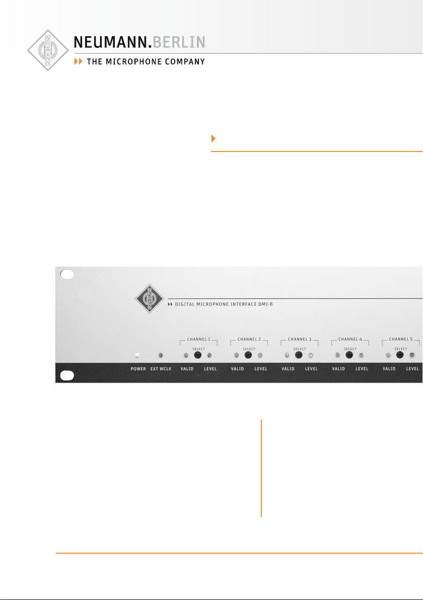
Anzeigen (Abb. 1)
POWER
Anzeige der Betriebsbereitschaft. Während des
Startvorgangs leuchtet die Anzeige mit reduzierter Helligkeit.
VALID
Anzeige eines gültigen AES42-Datenstroms vom
Mikrophon zum DMI-8. Die Anzeige blinkt, während das Mikrophon synchronisiert wird. Sie
leuchtet durchgehend, wenn ein gültiger Datenstrom empfangen wird und das Mikrophon erfolgreich synchronisiert ist.
LEVEL
Peak-Level-Anzeige (Multicolor LED) des Mikrophonsignals:
• Aus: kleiner –60 dBFS
• Grün: –60 dBFS bis –12 dBFS
• Orange: –12 dBFS bis –1,5 dBFS
• Rot: größ er –1,5 dBFS
EXT WCLK
Anzeige eines externen Synchronisationssignals
am WORD CLOCK (OR AES11)-Eingang. Die Anzeige ist aus, wenn kein externes Synchronisationssignal erkannt wird. Die Anzeige blinkt, wenn ein
Synchronisationssignal anliegt, aber noch keine
Synchronisation erreicht ist. Die Anzeige leuchtet
durchgehend, wenn das DMI-8 erfolgreich synchronis iert ist. Ein da uerhaftes Blinken der A nzeige
bedeutet, dass ein ungültiges Synchronisationssignal am DMI-8 angeschlossen wurde. Ursache:
keine gültige Word Clock-Frequenz (+/–50 ppm)
oder zu hohe Jitter-Werte.
Bedienelemente
SELECT
Ein Mikrophonkanal kann durch das Betätigen des
korrespondierenden Tasters selektiert werden.
Die VALID-Anzeige dieses Kanals erscheint dann
in oranger statt in grüner Farbe. Nochmaliges Betätigen derselben oder einer anderen Taste deselektiert den Mikrophonkanal.
GAIN +/–
Beim Betätigen der Taster wird die digitale Verstärkung im Mikrophon des selektierten Kanals in
1 dB-Stufen variiert.
Anschlüsse (Abb. 2)
WORD CLOCK (OR AES11) IN/OUT
In digitalen Studioeinrichtungen wird üblicherweise ein zentraler Word Clock oder ein AES11Signal zur Synchronisation der angeschlossenen
Geräte verwendet. Das DMI-8 synchronisiert sich
auf dieses externe Synchronisationssignal automatisch. Liegt kein Synchronisationssignal am
BNC-Eingang an, aktiviert das DMI-8 automatisch
2
D
3
D
D
Page 3
einen internen Word Clock-Generator. Am BNCAusgang steht das empfangene externe Synchronisationssignal bzw. der intern generierte Word
Clock zur Verfügung.
Auch im stromlosen Zustand des DMI-8 wird
ein externes Synchronisationssignal direkt zum
BNC-Ausgang durchgeleitet. Steckt auf der BNCAusgangsbuchse kein Kabel, wird eine automatische Terminierung (75 Ohm) des BNC-Eingangs
wirksam.
Auch bei externer Synchronisation wird der interne Clock Generator des DMI-8 (VCXO) zur Synchronisation der Mikrophone und zur Generierung
der Ausgangssignale benutzt. Hierbei wird der
VCXO mittels einer PLL auf das externe Synchronisationssignal synchronisiert, was zu einer sehr
eff ektiven Jitter-Unterdrückung führt.
AES42 IN
Acht 3-polige XLR-Eingänge zum Anschluss digitaler Mikrophone.
AES/EBU Out
25-polige Sub-D Buchsen mit YAMAHA- und TASCAM PINOUT für das AES/EBU-Ausgangssignal.
Das AE S/EBU-Signal enthält st andardgemäß 2 Audiokanäle. Die Audiodaten benachbarter MonoMikrophonkanäle werden folgendermaßen auf die
Audiokanäle des korrespondierenden AES/EBUAusgangs verteilt:
• Channel 1 AES/EBU Out
links: Mikrophon 1
rechts: Mikrophon 2
• Channel 2 AES/EBU Out
links: Mikrophon 3
rechts: Mikrophon 4
• Channel 3 AES/EBU Out
links: Mikrophon 5
rechts: Mikrophon 6
• Channel 4 AES/EBU Out
links: Mikrophon 7
rechts: Mikrophon 8
Der Ans chluss digitaler Stereomikrophone ist ausschließlich an den ungeradzahligen MikrophonEingängen möglich. Die Mikrophondaten belegen
für diesen Fall den linken und rechten Kanal des
korrespondierenden AES/EBU-Ausgangs.
ADAT OUT
Steckverbinder (Toslink) zur optischen Übertragung der 8 Mikrophonkanäle bei 44,1 kHz oder
48 kHz.
GN OUT
RJ 45 Buchse zur seriellen Übertragung der 8 Mikrophonkanäle in einem speziellen von Neumann
entwickelten Datenformat. Dieses Signal wird in
zukünftigen Neumann Multi-Kanal-Audio-Interfaces verwendet und dort z.B. auf Ethersound,
MADI usw. umgesetzt. Das spezielle Datenformat
erlaubt eine besonders einfache Weiterverarbeitung bei einer Word Clock Frequenz bis 192 kHz.
Gleichzeitig wird über diese Schnittstelle das
Neumann Multi-Kanal-Audio-Interface mit Strom
versorgt. Durch diese Maßnahmen wird eine
besonders kostengünstige Systemlösung mit
weitreichender Funktionalität und Flexibilität
erreicht.
CONTROL BUS (RS 485)
RJ 45-Buchsen zum Anschluss eines Computers
(PC/Mac). Als Anschlusskabel werden übliche
Ethernet- (Patch-)Kabel verwendet (Shielded
Twisted Pair – STP oder Unshielded Twisted Pair
– UTP).
Die Datenübertragung wird über eine RS 485Schnittstelle mit zusätzlichem Power-Anschluss
zur optionalen Versorgung eines externen Steuergeräts durchgeführt.
Achtung: Die RJ 45-Buchsen des DMI-8 dür-
fen nicht an ein Ethernet angeschlossen werden.
Die beiden RJ 45-Buchsen sind parallel verbunden, um mehrere DMI-Geräte kaskadieren und
von einem Rechner bedienen zu können.
Der Ans chluss an einen PC oder Mac wird über den
üblicherweise vorhandenen USB-Port realisiert.
Hierzu ist der Neumann USB/RS 485-Konverter
notwendig (nicht im Lieferumfang). Auf diese
Weise wird die Plug&Play-Fähigkeit vorhandener
USB-Anschlüsse mit der weitaus größeren möglichen Kabellänge (mind. 100 m) einer RS 485Verbindung genutzt .
ID [Geräteadresse]
Kodierschalter zur Einstellung der Geräteadresse.
Werden mehrere DMI s kaskadiert und gemeins am
gesteuert, müssen diese unterschiedliche Geräteadressen (ID) aufweisen.
Achtung: Erkennung der ID nur während des
Einschaltvorgangs, daher nach Änderung der ID
Stromversorgung kurz unterbrechen.
Zur Funktionsweise und Zuordnung der Geräteadressen s. Bedienungsanleitung der Steuerungssoftware RCS.
USER PORT
Direkte Steuerung der Mikrophonfunktionen
Mute, Light 1 und Light 2 (Auswahl mittels RCS)
durch ex terne Schaltkontakte oder Logik-Signale.
Die 9 Pins sind wie folgt belegt (low-aktiv):
Pin 1: Kanal 1
Pin 2: Kanal 2
Pin 3: Kanal 3
Pin 4: Kanal 4
Pin 5: Ground
Pin 6: Kanal 5
Pin 7: Kanal 6
Pin 8: Kanal 7
Pin 9: Kanal 8
Die Pins können wahlweise durch Verbinden nach
Ground oder durch Logik-Ausgänge angesteuert
werden (TTL-Logik-Pegel). Zum Beispiel können
für eine Stummschaltung mit einem einzigen Kontakt Mute aktiv iert und die rote LED ausgeschaltet
werden (z.B. für „On Air“-Funktion).
Achtung: Die jeweilige Schaltfunktion ist nur
dann aktiviert, wenn in der Steuerungssoftware
(RCS) der User Port für die Kontrolle der jeweiligen Funktion ausgewählt wurde.
4. Lieferumfang
• Digitales Mikrophon Interface DMI-8
• Netzkabel
• Bedienungsanleitung
• CD mit RCS-Software und USB-Treibern
5. Inbetriebnahme
Die folgenden Schritte erläutern die erstmalige
Installation eines digitalen Mikrophonsystems,
bestehend aus Mikrophon, Digitalem MikrophonInterface DMI-8 und Steuerungssoftware RCS.
Installieren Sie zuerst die RCS und die zugehörigen Treiber auf Ihrem Computer.
Für den Betrieb der Steuerungssoftware RCS bestehen an den Computer Mindestanforderungen,
die der Bedienungsanleitung für die RCS zu entnehmen ist.
Starten Sie die SETUP-Routine auf der beigefügten CD-ROM (Windows: „Setup“, Mac OS: „Install RCS“) und folgen Sie den Anweisungen auf
dem Bildschirm.
Achtung:
• Für die Installation der Software sind Administratorrechte erforderlich.
• Der Konverter USB 485 darf erst mit einem
USB-Port des Computers verbunden werden,
nachdem die RCS installiert wurde.
USB-Treiberinstallation
Nachdem die RCS installiert wurde, muss der
Schnittstellenkonverter USB 485 mit einem USBAnschluss des Computers verbunden werden. Auf
diese Weise ist sichergestellt, dass der mitgelieferte USB-Treiber, der für den Betrieb des Konverters erforderlich ist, geladen wird.
Weitere Verbindungen
Verbinden Sie den USB 4 85-Konver ter über PatchKabel (nicht im Lieferumfang) mit einer der RJ 45Buchsen (CTL BUS) des DMI-8.
Wählen Sie die Geräteadresse (ID) am DMI-8
(Kodierschalter an der Rückseite des DMI). Die
Adressvergabe sollte bei „0“ beginnen.
Achtung: Erkennung der ID nur während des Einschaltvorgangs des DMI-8; daher nach Änderung
der ID Stromversorgung kurz unterbrechen.
Stellen Sie die Verbindungen zwischen Mikrophon, DMI-8 und dem nachfolgenden Gerät (z.B.
Mischpult) her.
Soll das DMI und die angeschlossenen Mikrophone mit einem externen Word Clock oder
AES11-Signal synchronisiert werden, so verbinden Sie dieses über ein BNC-Kabel mit dem Word
Clock Eingang des DMI-8.
Bei Verwendung mehrerer DMIs werden diese
über den Steuerbus kaskadiert. Dazu wird ein
RJ 45-Patchkabel in die zweite RJ 45-Buchse (CTL
BUS) des DMI gesteckt und mit der RJ 45-Buchse
des nächsten DMI verbunden usw. Ebenfalls müssen die DMIs untereinander synchronisiert sein.
Hierzu ist der BNC-Ausgang (Word Clock oder
AES11) des DMI mit dem BNC-Eingang des jeweils
nächsten Gerätes zu verbinden.
4
D
5
D
Page 4
Schließen Sie das DMI-8 an das Stromnetz an und
starten Sie die RC S.
Achtung: Das DMI-8 muss eingeschaltet sein, bevor die RCS gestartet wird, damit das DMI-8 vom
PC/Mac erkannt wird. Alternativ kann zum Erkennen eines DMIs auch der Befehl Options/DMI ausgeführt werden.
Solange die RCS arbeitet, darf das Verbindungskabel zwischen Computer und USB 4 85-Konverter
nicht abgezogen werden, um ein unkontrolliertes
Verhalten des Computers zu vermeiden. Dies ergibt sich aus der Spezifi kation der USB-Schnittstelle.
Lange Mikrophonkabel und mehrfache Steckverbindungen führen zu einem Spannungsabfall
der Mikrophonspeisespannung und zu einer Verschlechterung des Jitter-Verhaltens insbesondere bei hohen Abtastraten. Verwenden Sie daher
möglichst durchgehende Kabelverbindungen
zwischen Mikrophon und DMI-8 und bei größeren
Distanzen ausschließlich AES/EBU-Kabel (Wellenwiderstand 110 Ohm).
Achten Sie darauf, dass die Mikrophone und alle
Geräte der digitalen Signalkette synchronisiert
sind. Am DMI-8 angeschlossene Mikrophone müssen immer im Synchronmodus betrieben werden,
unabhängig davon, ob in der nachfolgenden Signalket te Sample-Rate-Converter im Einsat z sind.
Die Übertragung nicht synchronisierter Mikrophonsignale wird vom DMI-8 nicht unterstützt.
Achten Sie beim Anschließen von Kabeln auf die
korrekte Verriegelung der Steckverbinder.
Verlegen Sie die Kabel so, dass sie keine Stolpergefahr darstellen.
Firmware-Update
Die Firmware im DMI-8 und in Neumann-Mikrophonen ist updatefähig. Updates können ohne
Öff nen des Geräts über die Steuerungssoftware
RCS durchgeführt werden (s. Bedienungsanleitung RCS).
6. Technische Daten
Zulässige klimatische Verhältnisse:1)
Betriebstemperaturbereich ...............0 °C … +45 °C
Lagerungstemperaturbereich ...... –20 °C … +70 °C
Feuchtebereich .......................max. 90 % rel. hum.
1)
Alle Werte für nicht-kondensierende Feuchtigkeit.
bei +20 °C
AES42 Eingänge ...................................... 8x XLR 3F,
Audiodaten entsprechend
AES/EBU- (AES3-) Datenformat,
Phantomspeisung (DPP),
Fernsteuerdaten
Phantomspeisung (DPP) ...............................+10 V,
max. 250 mA pro Kanal,
kurzschlussfest
Fernsteuerdaten ........................... Pulse (+2 V), der
Phantomspeisung überlagert,
ca. 750 Bit/s oder
9.600 Bit/s (mikrophonabhängig)
Ausgänge ........................... 2x SUB-D 25, AES/EBU-
(AES3-) Datenformat,
Yamaha und Tascam pinout,
1x Toslink, ADAT-Format bis 48 kHz,
1x RJ 45, GN-Format bis 192 kHz,
incl. Power Out Pin: ca. +15 VDC, max.1 A,
kurzschlussfest
Unterstützte Abtastraten .......................44,1 / 48 /
88,2 / 96 /
176,4 / 192 kHz
Mikrophon-
Synchronisation ............................AES42 – Mode 2
(synchroner Mode),
Tak tnachre gelung im Mikro phon
durch PLL.
DMI-8-
Synchronisation ..................................automatisch
auf externes Word Clock-
oder AES11-Signal,
sonst Aktiv ierung des internen
Word Clock-Generators.
Word Clock (oder AES11) Input ......................BNC
Vin...........................>100 mV an 75 Ohm
Word Clock (oder AES11) Output ......................BNC
Vout ... = Vi n (externe Synchronisa tion)
Vout ........................ ca. 1,5 V an 75 Ohm
(interner Word Clock Generator)
Interner Word Clock-
Generator ....................................44,1 / 48 / 88,2 /
96 / 176,4 / 192 kHz,
Genauigkeit ±25 ppm
Anzeigen .............................Power, Ext Word Clock,
Valid, Level (Mikrophon)
Bedienelemente ...................8x CHANNEL SELECT,
Control Bus ................................ 2x RJ 45-Buchsen,
Geräteadresse (ID) ......................................0 ... 15,
User Por t ............................................. 9-pol Sub-D,
Stromversorgung ...............90 ... 240 V, 50/60 Hz
Leistungsaufnahme .....................................< 55 VA
Abmessungen ......... (B x H x T) 483 x 8 8 x 210 mm
Gewicht .....................................................ca. 2,8 kg
Verbindung zum USB-Port
des Computers über
Neumann-Schnittstellen-
konverter USB 485,
für Kaskadierungszwecke
parallel verbunden.
RS 485 mit zusätzlichem
Power Out P in (ca. +11,3 V,
max. 500 mA)
einstellbar mit Kodierschalter
an der Geräterückseite.
1 Schaltfunktion pro Kanal
(Mute und/oder Light 1/2 wählbar)
7. Zusatzerläuterungen
7.1 AES42
Der Standard basiert auf der Verwendung 2-adriger symmetrischer Kabel (AES/EBU-Kabel,
bei kurzen Verbindungen auch herkömmliche
„Analogkabel“). Die Stromversorgung digitaler
Mikrophone ist als Digital Phantom Power (DPP)
von +10 V, max. 250 mA defi niert. Durch Modulation der Phantomspannung wird ein Fernsteuerdatenstrom in Richtung Mikrophon erzeugt
(+2 V-Pulse).
Das Datenformat des vom Mikrophon gesendeten
digitalen Audiosignals entspricht dem Standard
AES/EBU (AES3). Die in diesem Standard defi nierten Userbits sind zur Übertragung diverser
Informationen vorgesehen. Im Standard AES42
sind diese Userbits in ihrer Bedeutung für digitale Mikrophone defi niert. Im DMI-8 werden diese
Daten vom Audiosignal getrennt und zum Control
Bus (Schnittstelle für Computer oder Steuergerät)
geleitet.
Abb. 3 zeigt ein einfaches Funktionsdiagramm
eines Mikrophon-Interfaces mit AES42-Eingang
und AES/EBU-Ausgang.
GAIN +/–
7.2 XLR-Kabel
Die realisierbare Leitungslänge von einem digitalen Neumann-Mikrophon zum DMI-8 hängt von
dem verwendeten Kabeltyp und von der gewählten Sampling-Rate (Word Clock-Frequenz) ab.
Bei Längen bis zu 100 m bei 44,1/48 kHz-Abtastrate können hochwertige „analoge“ XLR3-Kabel
(z.B. IC 3 von Neumann) verwendet werden. Für
größere Leitungslängen wird die Verwendung
von AES/EBU-Kabeln (110 Ohm) erforderlich.
Typischerweise können in diesem Fall Längen
bis 300 m (Abtastrate 44,1/48 kHz) bzw. 200 m
(Abtastrate 88,2/96 kHz) bzw. 100 m (Abtastrate
176,4/192 kHz) realisiert werden.
Achtung: Bei längeren Verbindungen zwischen
Mikrophon und DMI-8 muss bei der Auswahl der
Kabel darauf geachtet werd en, dass der DC-Widerstand einen maximalen Wert nicht überschreitet.
Dies ist nötig, um unzulässigen Spannungsabfall
der Phantomspeisung zu vermeiden. Es gilt folgendes:
Ra/2 + Rs < 18 Ohm
Ra = DC-Widerstand der einzelnen Ader,
Rs = DC-Widerstand des Schirm s bzw. de r
GND-Rückleitung.
Die realisierbare Leitungslänge vom DMI-8 zum
nachfolgenden Gerät (z.B. digitales Mischpult)
hängt maßgeblich von den technischen Eigenschaften des nachfolgenden Geräts ab. Hierzu
können keine spezifi schen Aussagen gemacht
werden. Im Zweifel ist die Verwendung von AES/
EBU -Kabeln (110 Ohm) empfehle nswer t.
7.3 Betrieb ohne Steuerungssoftware RCS
Sämtliche Einstellungen, die beim Ausschalten
des DMI-8 wirksam sind, werden intern gespeichert und nach dem Wiedereinschalten automatisch in das Mikrophon geladen. Die letzten Mikrophoneinstellungen werden wiederhergestellt,
ohne dass hierfür eine Verbindung zum Steuergerät (PC/Mac) nötig ist.
Dies geschieht auch, wenn ein Mikrophon erst
später an das schon eingeschaltete DMI-8 angeschlossen wird.
Beim Starten der Steuerungssoftware RCS wird
die dort gespeicherte Konfi guration aller Mikrophonkanäle mit den im DMI-8 gespeicherten
Einstellungen verglichen. Werden Unterschiede
6
D
7
D
Page 5

erkannt, wird in einem Auswahl-Menü abgefragt,
welche Konfi guration übernommen werden soll
(s. Bedienungsanleitung RCS).
7.4 Synchronisation
Der Standard AES42 beschreibt zwei Arten der
Synchronisation des Mikrophons mit dem Empfänger (z.B. Mischpult oder Digitales MikrophonInterface – DMI-8):
Mode 1: Das Mikrophon arbeitet freilaufend mit
der Abtastrate seines internen Quarzoszillators
und benötigt auf der Empfängerseite einen A btastratenwandler (Sample-Rate-Converter). SampleRate-Converter können die Signalqualität bzgl.
Dynamikumfang verschlechtern und verlängern
die Latenzzeit.
8. Fehlercheckliste
Fehler
Ein am DMI angeschlossenes
und eingeschaltetes Mikrophon
wird an der RCS nicht angezeigt,
obwohl LED „VALID“ am DMI
leuchtet.
LED „Ext. Word Clk“ leuchtet
nicht, obwohl ein Ext. Word Clk
angeschlossen ist.
LED „Ext. Word Clk“ blinkt dauerhaft (kurzzeitiges Blinken nach
Aktivierung eines Ext. Word Clk ist
normal und zeigt den Synchronisationsprozess an).
Mögliche Ursachen
▶
DMI wird von der RCS Soft ware
nicht erkannt – Ursache:
Das DMI war beim Starten der RCS
noch nicht eingeschaltet.
Verwendung derselben ID bei
mehreren Geräten.
ID bei laufendem Betrieb geändert.
Falsche Einstellung für Schnittstelle (USB, COM1, COM2).
Es wird kein Word Clk – Signal
erkannt.
Word Clock Signal liegt an, wird
aber nicht als gültiges Signal interpretiert. Word Clock Frequenz
weicht z.B. mehr als ± 50 ppm vom
Sollwert ab.
Achtung: Dieser Modus wird vom DMI-8 nicht unterstützt.
Mode 2: Das Mikrophon wird vom DMI-8 synchronisiert. Hierbei wird im DMI-8 ein Frequenz/Phasenvergleich zwischen dem rückgewonnenen
Word Clock aus dem Mikrophonsignal und dem
Word Clock des DMI-8 durchgeführt. Aus der
ermittelten Phasenabweichung berechnet das
DMI-8 ein Regelsignal, das über den Fernsteuerdatenstrom zum Mikrophon übertragen wird und
dort die Frequenz des internen Quarzoszillators
steuert.
Der inter ne Word Clock-Ge nerator des DMI- 8 kann
über die BNC-Ausgangsbuchse zur Synchronisation weiterer DMIs und der weiterverarbeitenden
Geräte (z.B. Mischpult) verwendet werden.
Abhilfe
▶
RCS erst starten, nachdem das
DMI eingeschaltet wurde oder
Befehl Options/DMI ausführen und
Fenster wieder schliessen.
Einstellung durch Kodierschalter
auf der Geräte-Rückseite, für jedes
Ger ät eine and ere ID !
DMI muss nach einer ID -Änderung
neu eingeschaltet werden, danach
RCS neu starten oder Befehl Options/DMI ausführen und Fenster
wieder schliessen.
Richtige Schnittstelle in RCS über
Options/Communication wählen.
Word Clock Quelle und Kabelverbindung überprüfen.
Word Clock Frequenz überprüfen,
andere Quelle für Word Clock
wählen. Alternativ Ext. Word
Clk entfernen und DMI als Word
Clk Master für die Signalkette
verwenden.
Fehler
LED „VALID“ leuchtet nicht, obwohl
ein Mikrophon angeschlossen und
eingeschaltet ist (RCS-Anzeige „Mic
PWR“ leuchtet).
LED „VALID“ blinkt dauerhaft
(kurzzeitiges Blinken während
des Sychronisationsvorgangs ist
normal).
Steuerung von Funktionen über User
Port funktioniert nicht.
Mögliche Ursachen
▶
Kein gültiger Datenstrom.
Ursache:
Kabelverbindung zum Mikrophon
mangelhaft oder zu lang
Mikrophon wird nicht synchronisiert, weil die Word Clk - Frequenz
nicht unterstützt wird.
Mikrophon unterstützt nur
„Mode 1“ nach AE S42-Standard,
d.h. es ist nicht synchronisierbar.
User Port-Steuerung nicht freigegeben.
Abhilfe
▶
Kabelverbindung auf Unterbrechung prüfen.
Die für die gewählte Word Clk
Frequenz geltenden Grenzen
hinsichtlich max. Kabellängen
und erforderlicher Kabelqualität
beachten. Unnötige Übergangsstellen (Steckverbindungen) vermeiden. Siehe Kapitel 7.2, Kabel.
Eine Word Clk Frequenz auswählen, die von allen angeschlossenen
Mikrophonen unterstützt wird.
Synchronisierbares Mikrophon
verwenden (alle Neumann-Mikrophone der Solution-D-Serie).
Im Systemmenü der RC S Software
muss „Function controlled by
Userport“ für die gewünschte
Funktion aktiviert sein.
8
D
9
D
Page 6

1. Introduction
Th is ma nua l cont ains e sse ntial information for the
operation and care of the product you have purchased. Please read the instructions carefully and
completely before using the equipment. Please
keep this manual where it will be accessible at all
times to all current and future users.
Additional information, in particular concerning available accessories and Neumann service
partners, can be found on our website: www.neumann.com. Information about service partners
can also be obtained by telephone: +49 (0) 30 /
41 7 7 24 - 0.
The follo wing related fi le s are available in th e Downloads section of our website www.neumann.com:
Operating manual and fi rmware for digital mi-
•
crophones (D-01, KM D, TLM 103 D, etc.).
Operating manual and fi rmware for digital mi-
•
crophone interfaces (DMI-2, DMI-8, etc.)
Remote Control Software (RCS) and the corre-
•
sponding operating manual
Brief description of the AES42 Standard
•
Additional information concerning the digital microphone interface can be found at http://www.
aes.org/publications/standards/ under the title
“AES standard for acoustics – Digital interface for
microphones”.
The Neumann online forum enables Neumann users worl dwide to share their exper iences. Through
its integrated archive function, the forum has developed into an extensive knowledge pool.
2. Safety instructions
The Digital Microphone Interface DMI-8 provides
power and remote control for digital microphones
in accordance with to the international standard
AES42 and makes the microphone signal available in AE S/EBU format.
•
Connec t to the inputs only digital microphones
that comply with the AES42 standard.
•
When connecting other digital sources with
AES3 or AES/EBU outputs, the Digital Phantom Power (DPP) used to power digital microphones must be switched off .
•
Connect the outputs only to the corresponding
inputs of subsequent devices.
The RJ 45 ports – CONTROL BUS (RS 485)
and GN OUT – transmit DC voltage, and must
not be connected to an Ethernet.
Repairs and servicing are to be carried out
only by experienced, authorized service
personnel. Unauthorized opening or modifi cation of the equipment shall void the warranty.
Allow the equipment to adjust to the ambient
•
temperature before switching it on.
Do not operate the equipment in a damaged
•
condition.
Always run cables in such a way that there is no
•
risk of tripping over th em.
Ensure that liquids and electrically conductive
•
objects unless required for operation are kept
at a safe distance from the equipment and its
connections.
Do not use solvents or aggressive cleansers for
•
cleaning purposes.
Dispose of the equipment in accordance with
•
the regulations applicable to the respective
country.
Please note: All information relating to the microphones refers to digital microphones of the Neumann Solution-D series.
Disclaimer:
The product is sold “as-is” and the customer is assuming the entire risk as to the product’s suitability for his needs, its quality and its performance.
In no event will Neumann be liable for direct,
indirect, special, incidental or consequential damages resulting from any defect in the product or
from its use in conjunction with any microphones/
products from other manufacturers, even if advised of the possibility of such damages.
3. Description
The DMI-8 provides power and remote control for
digital microphones that operate in accordance
with the AES42 standard (see www.aes.org).
The most important functions of the DMI-8 are as
follows:
Providing a power supply and remote control
•
of 8 digital microphones (in accordance with
the AES42 standard).
Receiving and processing the audio data of the
•
microphone.
Generating output signals in AES/EBU, ADAT
•
and GN format.
Synchronizing the microphones w ith the DMI-8
•
word clock, in accordance with the AES42 standard Mode 2 (see Sec tion 7.4 Synchronization)
Automatically synchronizing the DMI-8 to an
•
external synchronization signal (word clock or
AES11)
•
Supporting all standard sampling rates: 44.1 /
48 / 88.2 / 96 / 176.4 / 192 kHz.
•
Providing a computer interface – control bus
(RS 485) – for transmitting and processing
bidirectional control data. For this purpose,
Neumann supplies the RCS remote control
software for use with a PC or Mac.
•
Providing a user port for direct control (via a
switch contact or low-active signal) of selected
functions (Mute, LED 1 and LED 2).
•
Cascading multiple (DMI-8 or DMI-2) devices.
•
Maintaining all settings for connected microphones in the DMI-8. When the power is
switched on, these settings are transmitted to
the microphones via the remote control data
stream; no computer connection is required.
Indicators (Fig. 1)
POWER
Indicates that the equipment is ready for operation. During the startup process, the indicator
shines less brightly.
VALID
Indicates a valid AES42 data stream from the microphone to the DMI-8. The indicator blinks while
the microphone is being synchronized. It shines
continuously when a valid data stream is being re ceived and the microphone has been successfully
synchronized.
LEVEL
Peak Level Indicator (multicolor LED) for the microphone signal:
Off : below –60 dBFS
•
Green: – 60 dBFS to –12 dBFS
•
Orange: –12 dBFS to –1.5 dBFS
•
Red: above –1.5 dBFS
•
EXT WCLK
Indicates that an external synchronization signal
is being fed to the WORD CLOCK (or AE S11) input.
If no external synchronization signal is detected,
the indic ator will not be lit up. The indicator bli nks
if a signal is present but synchronization has not
yet been achieved. The indicator shines continuously when the DMI-8 has been successfully synchronized. Continuous blinking of the indicator
means that an invalid synchronization signal is
being received by the DMI-8; this may be due to
an invalid word clock frequency (+/–50 ppm) or to
excessive jitter values.
Control elements
SELECT
A microphone channel can be selected by pressing the corresponding button. The VALID indicator for the channel will then appear orange rather
than green. Pressing this button again or pressing
another button deselects the microphone channel.
GAIN +/–
Pressing the GAIN buttons changes the digital
gain in the microphone of the selected channel in
steps of 1 dB.
Ports (Fig. 2)
WORD CLOCK (OR AES11) IN/OUT
In digital studio setups, a central word clock or an
AES11 signal is usually used for synchronizing the
connected equipment. The DMI-8 automatically
syn chronize s itself to this sync sig nal.
If there is no valid synchronization signal at the
BNC input, the DMI-8 automatically activates an
internal word clock generator. Either the received
external synchronization signal or the internally
generated word clock signal is available at the
BNC output.
Even in the absence of power, an external sync
signal is transferred by the DMI-8 directly to the
BNC output. If no cable has been attached to the
BNC output, a termination (75 ohms) is automatically enabled at the BNC input.
Even in the case of external synchronization, the
internal clock generator (VCXO) remains active
and is synchronized with the external sync signal
by means of a phase-locked loop (PLL), which results in very eff ective suppression of jitter.
EN
10
11
EN
Page 7

AES42 IN
Eight 3-pin XLR inputs for connecting digital microphones.
AES/EBU OUT
25-pin sub-D connectors with Yamaha and Tascam
pinout for the AES/EBU output signal.
The AES/EBU signal includes 2 standard audio
channels.
The distribution of the audio data of adjacent
mono microphone channels between the audio
channels of the corresponding AES/EBU output
signal is as follows:
•
Channel 1 AES/EBU OUT
Left: microphone 1
Right: microphone 2
•
Channel 2 AES/EBU OUT
Left: microphone 3
Right: microphone 4
•
Channel 3 AES/EBU OUT
Left: microphone 5
Right: microphone 6
•
Channel 4 AES/EBU OUT
Left: microphone 7
Right: microphone 8
Digital stereo microphones are supported at oddnumbered AES42 microphone inputs only. In this
case the audio data of the microphone s are routed
to the lef t and right channels of the corresponding
AES/EBU output.
ADAT OUT
Connector (Toslink) for the optical transmission
of the 8 microphone channels at 44.1 kHz or
48 kHz.
GN OUT
The RJ 45 connector for serial transmission of
the 8 microphone channels employs a special
data format developed by Neumann. This signal
will be used by Neumann multi-channel audio
interfaces in the future for converting to formats
such as Ethersound, MADI, etc. This special data
format permits very simple processing for word
clock frequencies of up to 192 kHz. The GN OUT
simultaneously supplies power for the Neumann
multi-channel audio interfaces. The result is a
very cost-eff ective system solution with extensive
functionality and fl exibility.
CONTROL BUS (RS 485)
RJ 45 ports for connecting a computer (PC or
Mac). Standard Ethernet (patch) cables are used
(Shielded Twisted Pair – STP or Unshielded Twisted Pair – UTP).
Da ta tr ans fer i s perf orm ed via a n RS 48 5 int erf ace
with an additional power-out pin, for the optional
supply of an ex ternal control device .
Attention: The RJ 45 ports of the DMI-8 must
not be connected to an Ethernet.
The two RJ 45 ports are connected in parallel, in
order to permit multiple DMI devices to be cascaded and controlled by a single computer.
The DMI-8 is connected to the normally available USB port of a PC or Mac. The Neumann USB/
RS 485 converter (not included) is required for
this purpose. This permits the plug-and-play capa bility of ex ist ing U SB po rts to be co mbin ed wit h
the much greater cable leng ths (of 100 m or more)
that are possible with an RS 485 connection.
ID [device address]
A coding switch permits setting of the device address. If multiple DMI devices are cascaded and
controlled by a single computer, they must have
diff erent device addresses (IDs).
Attention: Th e ID is d ete cte d on ly du rin g the pow er-up process. After the ID is changed, the power
supply must therefore be interrupted briefl y and
then turned back on again.
Please see the RCS control software operating
manual for information concerning the mode of
operation and assignment of device addresses.
USER PORT
The user port permits the direct control of the
microphone functions Mute, Light 1 and Light 2
(selected via RCS) by means of external switch
contacts or logic signals.
The assignments of the 9 pins are as follows (lowactive):
pin 1 channel 1
pin 2: channel 2
pin 3: channel 3
pin 4: channel 4
pin 5: ground
pin 6: channel 5
pin 7: channel 6
pin 8: channel 7
pin 9: channel 8
The pins can be controlled via contact with
ground, or alternatively by means of logic outputs
(TTL logic level). For instance, with a single contact, Mute can be activated and the red LED can
be switched off (e.g. for the On Air function).
Attention: The respective switch function is activated only when User Port is selected in the RCS
control software, for the control of the particular
function.
4. Equipment supplied
DMI-8 Digital Microphone Interface
•
Power cable
•
Operating manual
•
CD with RCS sof tware and USB drivers
•
5. Setup
The following steps are to be carried out for the
initial installation of a digital microphone system
consisting of the microphone, the DMI-8 Digital
Microphone Interface and the RCS control software.
First install the RCS and the associated drivers on
your computer.
The minimum computer requirements for operating the RCS control software are specifi ed in the
RCS operating manual.
Start the setup program on the enclosed CD-ROM
(Windows: “Setup”; Mac OS: “Install RCS”) and
follow the instructions displayed on the screen.
Attention:
Administrator rights are required in order to
•
install the software.
The USB 485 converter must not be connected
•
to a computer USB por t until after the RCS software has been installed.
USB driver installation
After the RCS has been installed, the USB 485
converter must be connected to the computer
USB port. This ensures loading of the supplied
USB driver, which is required for operation of the
converter.
Other connections
Connec t the USB 485 converter to one of the RJ 45
ports (CTL BUS) of the DMI-8 by means of a patch
cable (not included).
Set the device address (ID) of the DMI-8 (by using the coding switch on the back of the DMI). Addresses should be assigned beginning w ith “0”.
Attention: The ID is detected only during the
power-up process of the DMI-8. After the ID is
changed, the power supply must therefore be interrupted briefl y and then turned back on again.
Connect the microphone, the DMI-8 and the subsequent device (e.g. a mixing console)
If the DMI and the connected microphones are to
be synchronize d with a n exter nal s ynch roni zation
signal (a word clock or AES11 signal), use a BNC
cable to connect the sync signal to the word clock
input of the DMI-8.
If multiple DMIs are used, they are cascaded via
the control bus. For this purpose, use an RJ 45
patch cable to connect the second RJ 45 port of
the fi rst DMI to one of the RJ 45 ports of the next
DMI, etc.
Since the DMIs must also be synchronized with
one another, connect the BNC output (word clock
or A ES1 1) of e ach D MI to t he BN C inpu t of the s ubsequent device.
Connect the DMI-8 to the power supply system
and star t the RCS software.
Attention: The DMI-8 must be switched on before
the RCS is started so that the DMI-8 will be detected by the PC or Mac. Alternatively, the command Options/DMI can be used to detect a DMI.
Due to USB interface specifi cations, in order to
prevent uncontrolled operation of the computer,
while the RC S is running, the cable connecting the
computer to the USB 485 converter must not be
disconnected.
Long microphone cables and multiple connectors
lead to a drop in the microphone supply voltage
and to an increase of jitter, particularly in the
case of high sampling rates. Therefore, if possible, use continuous cable between the microphone and the DMI- 8, and between the DMI-8 and
subsequent equipment. For longer distances use
AES/EBU cable exclusively (with an impedance of
110 ohms).
Ensure that the microphones and all devices in
the digital signal chain are synchronized. Micro-
EN
12
13
EN
Page 8

phones connected to the DMI-8 must always be
operated in synchronous mode, whether or not
sample rate converters are used in the subsequent signal chain. The transmission of none synchronize d microphone sig nals is not supported by
the DMI-8.
Ensure correct fastening of the connectors when
connecting the cables.
Lay the cables in such a way that they do not present a tripping hazard.
Updating of fi rmware
The fi rmware in the DMI-8 and in the Neumann
microphones is updatable. Updates can be performed without opening the equipment, via the
RCS control software (see the RCS Operating
Manual).
6. Technical data
Permissible atmospheric conditions
Operating temperature .....................0 °C to +45 °C
Storage temperature .....................–20 °C to +70 °C
Relative humidity ...................max. 90 % at +20 °C
AES42 input s: .........................................8x XLR3F ,
Phantom power (DPP): ...................................+10 V,
Remote control data: .........................Pulses (+2 V),
Output s: ..............................2x SUB-D 25, AES/EBU
incl. power-out pin: approx. +15 VDC, max.1 A,
Sampling rates supported: ....................44.1 / 48 /
1)
A ll values are f or non-con densing hum idity.
Audio data in accordance with
AES/EBU (AE S3) data format,
Digital phantom power (DPP)
max. 250 mA per channel,
approx. 750 bits/s or 9,600 bits/s
(depending on the microphone)
Yamaha and Tascam pinout,
1x Toslink, ADAT fo rmat up to 4 8 kHz,
1x R J 45, GN format up to 192 kHz,
1)
Remote control data
short-circuit proof
superimposed on the
phantom power,
(AES3) data format,
short-circuit-proof
88.2 / 96 kHz /
176.4 / 192 kHz
Microphone
synchronization: ............................AES42 – Mode 2
Microphone clock control via PLL
DMI-8
Synchronization ....... automatically to an external
if present, otherwise the internal
word clock generator is activated.
Word clock (or AES11) input ............................BNC
Vin ....................................... >100 mV at 75 ohms
Word clock (or AES11) output ...........................BNC
Vout .................= Vin (external synchronization)
Vout ..............................approx. 1.5 V at 75 ohms
(internal word clo ck gener ator)
Internal word clock
generator: ...................... 4 4.1 / 48 / 88.2 / 96 kHz/
Indicators:............... Power, Ext Word Clock, Valid,
Control element s: .......................8x Channel Select
Control bus: .....................................2 x RJ 45 port s;
connection to computer USB port
power-out pin (approx. +11.3 V,
Device address (ID): ........... 0 to 15, adjustable via
User port: .............................................9-pin sub-D,
Power supply: .................90 V to 240 V; 50/60 Hz
Power consumption: .....................................<55 VA
Dimensions: ...........(W x H x D) 483 x 88 x 210 mm
Weight: ..............................................approx. 2.8 kg
(synchronous mode)
word clock or AES11 signal,
176.4 / 192 kHz
Accuracy ±25 ppm
Level (microphone)
GAIN +/–
via the Neumann USB 485
interface converter;
connected in parallel
for the purpose of cascading.
RS 485 with additional
max. 500 mA)
coding switch on the back
of the device
1 switch function per channel
(Mute and/or Light 1/
Light 2 selectable)
7. Addit ional information
7.1 AES42
This standard is based upon the use of a 2-line
balanced cable (AES/EBU cable; for short connections conventional analog cable can also be
used). The power supply for digital microphones
is defi ned as Digital Phantom Power (DPP) with
+10 V and max. 250 mA. Modulation of the phantom voltage generates a remote control data
stream which is transmitted to the microphone
(+2 V pulses).
The data format of the digital audio signal transmitted from the microphone complies with the
AES/ EBU (AES3) stan dard. The user bit s defi ne d in
this standard are intended for the transmission of
various types of infor mation. The AE S42 standard
defi nes the signifi cance of these user bits with regard to digital microphones. In the DMI-8, these
data are separated from the audio signal and are
transferred to the control bus, which serves as an
interface for a computer or control device.
Fig. 3 shows a simple functional diagram of a microphone interface with an AES42 input and an
AES/EBU output.
7.2 XLR cables
The leng th of cable that can be used from a digital
Neumann microphone to the DMI-8 is dependent
upon the type of cable and upon the sampling
rate (word clock frequency) selected. For cable
lengths of up to 100 m with a sampling rate of
44.1 kHz or 48 kHz, high-quality “analog” XLR 3
cable (e.g. the Neumann IC 3 cable) can be used.
For greater cable lengths, the use of AES/EBU
cables (110 ohms) is required. If AES/EBU cables
are used, the following cable lengths are typical: Up to 300 m for sampling rates of 44.1 kHz
or 48 kHz; up to 200 m for sampling rates of
88.2 kHz or 96 kHz; and up to 100 m for sampling
rates of 176.4 kHz or 192 kHz.
Attention: If a long cable is used to connect the
microphone and the DMI-8, the DC resistance of
the cable used must not exceed a specifi ed maximum value, since excessive DC resistance would
result in an impermissible voltage drop in the
phantom power. The following formula applies:
Rc/2 + Rs < 18 ohms
Rc = DC r esist ance of the indiv idual c able core,
Rs = DC resistance of the shield or the GND re-
turn line.
The length of cable that can be used from the
DMI-8 to subsequent equipment (e.g. a digital
mixing console) is substantially dependent upon
the technical features of the subsequent equipment. Thus no specifi c statements can be made
concerning the cable length. In case of doubt,
the use of AES/EBU cables (110 ohms) is recommended.
7.3 Operation without the RCS control software
All of the settings which are in eff ect when the
DMI-8 is switched off are stored internally, and
are automatically sent to the microphone when
the equipment is switched on again. The most
recent microphone settings are restored, without
requiring a connection to the control device (PC
or Mac).
The same procedure is followed if a microphone is
connected to the DMI-8 later, after the DMI-8 has
already been switched on.
When the R CS control sof tware is star ted, the confi gurations stored there for all of the microphone
channels are compared with the settings stored in
the DMI-8. If diff erences are detected, a menu is
displayed that asks which confi guration is to be
used (see the RCS Operating Manual).
7.4 Synchronization
The AES42 standard describes the following two
modes for synchronizing the microphone with the
receiver (e.g. a mixing console or the DMI-8 Digital Microphone Interface).
Mode 1: The microphone operates asynchronously, using the sampling rate of its internal quartz
oscillator. In this case, a sample rate converter is
required at the receiver. It should be noted that
sample rate conver ters can impair the signal quality in terms of dynamic range and enlarge the latency time.
Attention: This mode is not supported by the
DMI-8
Mode 2: The microphone is synchronized by the
DMI-8 . In this case, the D MI-8 performs a freq uency/phase comparison between the word clock
EN
14
15
EN
Page 9

signal recovered from the microphone signal,
and the word clock of the DMI-8. From the phase
deviat ion thus determined, the DMI-8 calculates a
control signal which is transmitted via the remote
control data stream to the microphone, where it
controls the frequency of the internal quartz oscillator.
8. Troubleshooting
Problem
The RCS does not indicate that a
microphone is switched on and
connected to the DMI, even though
the “VALID” LED on the DMI is
lit up.
The “Ext. Word Clk” LED is not lit
up, even though an external word
clock has been connected.
The “Ext. Word Clk” LED blinks
continuously. (Blinking for a short
period following activation of an
external word clock is normal, and
indicates that the synchronization
process is being carried out).
The “VALID” LED is not lit up, even
though a microphone is connected
and switched on. (The RCS “Mic
PWR” display is lit up).
Possible causes
▶
The DMI is not recognized by the
RCS software. – Cause:
The DMI was not switched on
at the time when the RCS was
started.
The same ID has been used for
more than one DMI.
The ID has been changed while the
DMI was in operation.
Incorrect interface setting (USB,
COM1 or COM2).
No word clock signal has been
detected.
A word clock signal is present,
but has not been interpreted as a
valid signal. This can occur, for example, if the word clock frequency
dev iates by more than ±50 pp m
from the nominal value.
No valid data stream – Cause:
The microphone cable connection
is faulty or too long.
Via the BNC output, the internal word clock generator of the DMI-8 can be used to synchronize
additional DMIs and connected equipment, such
as a mixing console.
Solution
▶
Do not start the RCS until the DMI
has been switched on, or execute
the command Options/DMI and
then close the window again.
Set the ID by means of the coding
switch on the back of the DMI;
each DMI must have a diff erent ID!
After an ID is changed, the DMI
must be restarted. Then restart
the RCS, or execute the command
Options/DMI and then close the
window again.
Select the correct interface in the
RCS via the command Options/
Communication.
Check the source of the word clock
signal and the cable connection.
Check the word clock frequency or
select another source for the word
clock signal. Alternatively, remove
the external word clock and use
the DMI internal word clock as the
master word clock for the signal
chain.
Check to ensure a continuous
cable connection.
Comply with the recommended
maximum cable length and
required cable quality, as applicable for the selected word clock
frequency. Avoid unnecessary
transition points (connectors). See
Section 7.2, Cables.
Problem
The “VALID” LED blinks continuously. (Blink ing for a short per iod
during the synchronization process
is normal).
Functions cannot be controlled via
the user port.
Possible causes
▶
The microphone has not been
synchronized because the selected word clock frequency is not
supported.
The microphone supports only
“mode 1” in accordance with the
AES42 standard, i.e. it cannot be
synchronized.
Control via the user port has not
been activated.
Solution
▶
Select a word clock frequency that
it is supported by all of the connected microphones.
Use a microphone that can be
synchronized (any Neumann Solution-D series microphones).
In the RCS system menu, “Functio n controlled by user port”
must be activated for the relevant
functions.
EN
16
17
EN
Page 10

Word Clock
IN
OUT
Abb. 1 / Fig. 1
Abb. 2 / Fig. 2
Digital
Mic.
Abb. 3 / Fig. 3
AES42 AES/EBU
Control Data + Control Data
DPP
DPP(+10V)
Control
(Computer)
Control Bus
Device
Receiver
(e.g. Mix. Console)
18
19
Page 11

Konformitätserklärung
Die Geo rg Neumann GmbH erklär t, dass diese s Gerät
die anwendbaren CE-Normen und -Vors chriften er füllt.
Neumann ist in zahl reichen Ländern eine ein getragene
®
Marke der Georg Neumann GmbH.
Further product names used here are trademarks or registered trademarks of the respective manufacturers and herewith will be accepted.
Irrtümer und technische Änderungen vorbehalten • Errors excepted, subject to changes
Printed in Germany • Publ. 1 2/08 533124/A01
Declaration of Conformity
Georg N eumann GmbH hereby declares that this dev ice
conforms to the applicable CE standards and regulations.
Neumann is a registered t rademark of the
®
G eorg Neumann GmbH in certain countries.
 Loading...