

Page 1

SCHNEIDER DIGITAL MICROPHONES FOR HIGH RESOLUTION AUDIO
DIGITAL MICROPHONES FOR HIGH RESOLUTION AUDIO
MARTIN SCHNEIDER1
1
Georg Neumann GmbH, Berlin, Germany
schneidm@neumann.com
Microphones with digital output format have appeared on the market in the last few years. They integrate the functions
of microphone, preamplifier, and analogue-to-digital converter in one device. Properly designed, the microphone
dynamic range can thus be optimally adapted to the intended application. The need to adjust gain settings and trim
levels is reduced to a minimum. Dynamic range issues inside and outside the microphone are discussed. Advantages of
digital microphones complying with AES 42, with a wide dynamic range and 24-bit resolution are shown.
INTRODUCTION
One should first define the term “digital microphone” in
the context of this article. A possible classification
could comprehend:
- a transducer where the underlying acousticalmechanical-eletrical transduction principle
contains a quantization,
- a combination of separate transducers, each
responsible for certain quantization steps,
- a microphone integrating an analog-to-digital
converter (ADC).
The first category describes the “purely digital”
transducer. The first microphone by Philipp Reis [1], a
single contact transducer, represented such a transducer,
albeit with very low quality due to the 1-bit resolution.
This is the only purely digital transducer known to the
author.
In the second category we find e.g. an optical
microphone, where the position-dependant displacement
of a diaphragm is traced with distinct light rays. The
reflected rays excite separate sensors, whose outputs are
combined into a single signal [2]. Another, electrostatic
transducer experiment shows the diaphragm as part of
the ADC, as component for the electrical / acoustical
summation in the feedback loop of a Σ∆-converter [3].
To obtain dynamic ranges comparable to the 120130 dB of standard analogue microphones, these
principles would need to be scaleable over 6 orders of
magnitude, a feat hardly achievable due to the extreme
mechanical precision involved.
Current microphone technology thus focuses on the
third category: microphones with integrated ADC. Here,
a purist could further differentiate between
- microphones with ADC output modules,
- microphones with ADC in closest proximity to
the transducer,
where the first subcategory would describe a complete
microphone, just with an added ADC module; the
second subcategory represents transducers where the
transducing element itself is closely integrated with the
analogue-to-digital conversion process. In the context of
high resolution audio it will be clear that the preferred
transducer should be of the electrostatic (condenser)
type, as this principle still yields the highest
performance regarding parameters like linearity,
dynamic range and frequency range.
1 HISTORICAL DEVELOPMENT
Possibly the first realization, in 1989, incorporating an
ADC in the same housing with an electro-acoustical
transducer is mentioned in [4]. The corresponding
electret condenser microphone by Ariel company was
intended for use with the now defunct NeXT computer,
with the then available 16 bit transducers and a stated
dynamic range of 92 dB. A 1995 prototype by Konrath
[5] put an ADC circuit inside the housing of a
commercial microphone. It featured a 7-pin XLRconnector and dedicated supply, delivering a multitude
of supply voltages to the circuit. A later commercialised
version by Beyerdynamic (MCD100) simplified this setup with the adoption of phantom power, similar in
AES 31st International Conference, London, UK, 2007 June 25–27
1
Page 2
SCHNEIDER DIGITAL MICROPHONES FOR HIGH RESOLUTION AUDIO
principle to P48 defined in IEC61938 [6], but adapted to
the lower voltage and higher current requirements of
ADC components. It already featured a gain ranging
ADC, to be discussed later, and limited remote control
functions (pre-attenuation) but yielded sub-optimal
noise figures, compared to standard analogue microphones. Another proprietary solution was presented by
Milab [7].
Although the mentioned developments could not fully
compete technically with state-of-the-art analogue
microphones, they were helpful in starting discussions
amongst manufacturers on the future of digitisation in
microphones. It was found that, before presenting
microphones with digital output to a wide public, all
questions of power supply, interfacing, connector types,
remote control etc. should be put into a public standard,
to allow future products to interconnect between
manufacturers. Accordingly, the German DKE 742.6
committee served as a starting basis, then handing over
to an AES standardization committee to publish the
AES 42-2001 standard [8,9], currently revised to the
2006 edition. Almost ten international microphone
manufacturers were actively or passively involved,
guaranteeing a common consensus. First microphones
complying with the new standard were presented in
2001, as a full-feature large diaphragm microphone
[10], later followed by a measurement microphone [11]
and small diaphragm capsule systems [12,13].
In contrast to the professional audio approach, trying to
provide highest possible audio quality, recently other
solutions have been presented, driven by computer
technology, i.e. mainly USB-powered microphones,
with currently in comparison very limited specification
ranges [14].
2 REASONS AND REQUIREMENTS FOR
DIGITAL MICROPHONES
Analogue output condenser microphones are now, 90
years after their invention by E.C. Wente, certainly a
mature technology. In a professional set-up, with
appropriate cabling and limited outside interferences, a
very high dynamic range of up to 130 dB-A can be
transduced [15,16]. To reduce effects of cable length
and interferences on the comparatively small
microphone output signal, preamplifiers are often
located in close proximity to the microphones. In any
case, proper level matching of all analogue components
is necessary to guarantee optimal signal transmission,
allowing for sufficient head-room and foot-room in the
process. On the other hand, digital technology provides
potentially loss-less transmission, once the analogue-todigital conversion has taken place. Accordingly, the
interest for microphones with digital output arose when
high quality ADC technology became available,
allowing conversion only minimally affecting microphone specifications.
Some of the requirements on digital microphones [8]
later realized in the AES 42 standard [9] were
- physical layer interface & protocol
compatibility: AES3 protocol with overlaid
phantom power, using 3-pin XLR connectors,
- control information from
the microphone: via
user bits in the AES3 data stream,
- control information to
the microphone: via low
frequent modulation of the phantom power
voltage.
With the chosen interface, loss-less transmission can be
performed over approximately 100 m also with highquality “analogue” microphone cable, approximately
300 m with AES3 “digital” cable. This compares well
with typical values for high-quality analogue set-ups.
An essential point in digital technology is proper
synchronization of all audio streams to a reference
clock. In a minimal set-up a receiver can synchronize to
a single microphone, although this would be in contrast
to typical studio procedures, where either the mixing
console, or a dedicated reference clock provide the
clocking reference. But, with multiple digital microphones one needs to either work with sample rate
converters in every channel at the receiver side (AES42
mode1), or preferably synchronize the microphones to
the reference clock (AES42 mode2). High quality
sample rate converters do increase the cost, and even
though in their current embodiments [17,18] they might
not influence the signal much, they will increase
processing time and thus add to the overall latency,
which can become prohibitive in some applications, e.g.
where direct monitoring is called for.
Sending the clock signal directly to the microphone
would imply multi-lead cables, incompatible with
standard 2-wire+ground/return studio wiring. The
solution adopted by AES42, after extensive tests, was to
integrate a voltage controlled crystal oscillator (VCXO)
inside the microphone, yielding an already very stable
data stream but where the frequency is dynamically fine
tuned from the receiver side via the control information
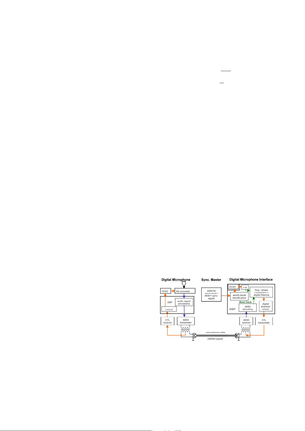
sent to the microphone (Fig. 1).
Figure 1: Connection of a digital microphone, with
synchronization using AES42 interface specification.
Microphone sample rate is controlled (CTL), comparing
extracted microphone rate and external word clock.
AES 31st International Conference, London, UK, 2007 June 25–27
2
Page 3

SCHNEIDER DIGITAL MICROPHONES FOR HIGH RESOLUTION AUDIO
A
A
The essential requirement then for digital microphones
remains to integrate A-to-D conversion providing
dynamic range and resolution comparable to their high
quality analogue counterparts.
3 DYNAMIC RANGE AND NOISE
In order to be able to compare possible benefits of
analogue and digital microphones, one has to look at the
limiting factors, i.e. the behaviour at very small and
large signal levels, corresponding to the noise floor and
the overload characteristics, as well as the typical signal
resolution, with a medium level signal present.
As mentioned, the typical dynamic range of the output
of a condenser microphone capsule can exceed 130 dB,
with typical maximum levels at a surprisingly high
+10 dBu (2.5 V
) and microphone self noise at
RMS
-120 dBu (A-weighted). In the most noise free of
current studio microphones this corresponds to sound
pressure levels of 7 to 137 dB SPL, covering the needs
of most applications. Only in excessively loud settings
will there be a need to (manually) switch the preattenuation on, shifting the microphone’s dynamic range
to higher levels.
D
Microphone Preamplifier
Capsule Impedance Output
Converter Stage
DC
Figure 2: Simple analogue signal chain, with condenser
microphone.
The typical noise voltage n
of a condenser micro-
mic
phone in Fig. 2 roughly follows a pink noise characteristic, whereas dynamic microphones, preamplifiers
and AD converter inputs produce basically white noise.
Preamplifier equivalent input noise n
(EIN) depends
pre
on the amount of gain v chosen. Concentrating all
necessary gain inside the preamplifier, the sum of
analogue equivalent input noise in an analogue
recording chain with ADC will be
)( vnvnnn
,
++=
2222
ADInpremicanasum
. (1)
The physical limit for preamplifier noise is determined
by the thermal noise of the input load R
fkTRn
∆= 4
(2)
min,
ipre
i
with k = 1,38*10-23 J/K (Boltzmann constant), T as
temperature, and ∆f as the bandwidth. For a typical
microphone output impedance of R
= 200 Ω, nR
i
calculates to -129 dBu (∆f = 23 kHz), or -131.7 dBu-A.
At high gain settings many preamplifiers show noise
figures close to this physical limit, but at low gain
settings n
might be as high as -100…-80 dBu, and is
pre
seldom published in the specifications. One sees that
preamplifier noise is higher or lower than the above
mentioned microphone self noise of -120 dBu-A, and
one main task for the recording engineer is then to
optimise this sum, keeping preamplifier and ADC input
headroom in mind. In analogue set-ups, the rule is to
pull up the gain to studio reference level, trying to avoid
clipping or distortion even with unforeseen very high
sound pressure levels.
The working dynamic range of a typical microphone /
preamplifier combination is shown in Fig. 3. The output
level of the preamplifier U
is shown over gain v.
out,pre
ADC noise is left out, for simplification, and assuming
that the preamplifier gain will be optimally set, so that
microphone and preamplifier noise dominate. The
limitations are then given by:
o n
: -131.7 dBu-A thermal resistive noise as
200Ω
physical limitation,
o n
: preamplifier equivalent input noise (A-
pre
weighted),
o Max
: maximum preamplifier output level,
pre
here: +20 dBu
o n
o Max
: microphone self noise, here: -120 dBu-A
mic
: maximum microphone output level,
mic
here: +6 dBu
One sees that the preamplifier noise n
reduces the
pre
maximum dynamic range of the microphone Dyn(Mic)
by approx. 16 dB, to a maximum resultant working
dynamic range Dyn(Max) of 110 dB. At the upper/right
axis the diagonal curves of constant equivalent input
sound pressure level are given values, for a microphone
with sensitivity M
= 12mV/Pa.
0
Figure 3: Dynamic range of a combination analogue
microphone / preamplifier
The situation is different in the case of digital
microphones with integrated ADC, as in Fig. 4. The
capsule parameters can be chosen by the designer so
that the capsule output levels are perfectly matched to
the ADC input requirements. The noise sum then
reduces to
22
, ADInmicdigsum
nnn += . (3)
Accordingly, the curve for preamplifier noise in Fig. 3
is replaced by the ADC noise n
. The noise over gain
ADIn
AES 31st International Conference, London, UK, 2007 June 25–27
3
Page 4

SCHNEIDER DIGITAL MICROPHONES FOR HIGH RESOLUTION AUDIO
diagram for digital microphones is shown in Fig. 5. The
dynamic range is vastly increased, especially for the
small gain values often used with condenser
microphones, and most importantly becomes
independent of the chosen gain setting. It is now only
limited by the microphone specifications, and by the
digital processing limits, i.e. 0 dBFS level.
Note: The gain shown in Fig. 5 is performed after the
ADC, i.e. in the digital domain.
A
D
Microphone ADC
Capsule Impedance
Converter
Figure 4: Condenser microphone, with integrated ADC
noise n
approx. 7 dB higher, yielding -133 dBFS-A.
ADIn
Adding a real condenser capsule, the thermal/acoustical
capsule noise n
means that the thermal/acoustical noise n
capsule and the electrical noise n
adds another 3 dB (-130 dB-A). This
caps
of the
caps
of the combined
ADIn
impedance converter and ADC are roughly at the same
level. To achieve even lower values, one would thus
have to work on optimising both electronics and
capsule.
As a side effect, the benign noise of the analogue
components, capsule and impedance converter, with its
largely gaussian distribution serves as an efficient dither
on the ADC quantization noise [19]. With typical
capsule parameters of small and large diameter condenser capsules, the summed noise n
can be at a
sum,dig
level of -122 dBFS or -130 dBFS (A-weighted),
respectively.
4 ADC CHARACTERISTICS
Fig. 6 shows an ADC with dynamic range of 140 dB-A.
ADC circuits matching such a vast dynamic range
would be of the gain ranging type, combining two or
more ADCs working at different signal levels. This is
one realization of a floating point converter, with
exponents of 2
0
and 24 [20,21].
Figure 5: Dynamic range of a digital microphone
Figure 6: Noise spectra (16k samples, 32x averages) of
an ADC with a. input short-circuited (-140 dBFS-A,
lower curve), b. impedance converter and equivalent
capsule capacitance (-133 dBFS-A, middle curve),
c. impedance converter and real capsule
(-130 dBFS-A, upper curve).
A more detailed perspective of the noise components is
presented in the spectra of Fig. 6. With the input shortcircuited, the ADC shows a roughly white noise
characteristic n
, typical of today’s Σ∆ –ADCs, with
ADC
slightly increasing noise above 20kHz, due to noise
shaping algorithms. Reduced to a single value, the
shown noise is in the region of -140 dBFS-A. The
analogue impedance converter, loaded by a typical
equivalent capsule capacitance, overlays this with a
Figure 7: Simple gain ranging ADC circuit [10]
400mV
Path-1 clipped
0V
-400mV
400mV
0V
-400mV
0s 0.5ms 1.0ms 1.5ms 2.0ms 2.5m s 3.0ms
Path-1
Path-2
V
V - Path-2)
Very precise signal matching required
to avoid glit ches and amplitude error s
Critical switching
Time
Figure 8: Signals in combined ADCs of Fig. 7, with
audible “glitches” in the summed signal [10]
As is well known, switching directly between ADCs
working at different levels can lead to artefacts like
“glitches” (see Fig. 8), or noise modulation [20,21],
when signal levels pass the switching level. The noise
floor of an ADC is typically wide-band white noise.
This white noise then becomes most audible when it is
modulated by a low frequent signal, not masking the
AES 31st International Conference, London, UK, 2007 June 25–27
4
Page 5

SCHNEIDER DIGITAL MICROPHONES FOR HIGH RESOLUTION AUDIO
higher frequent white noise components. One possible
way to reduce this effect is a non-linear network,
keeping both ADCs always in operation, and summed,
depending on the signal level, as shown in Fig. 9 & 10.
Figure 9: Gain ranging ADC circuit, with non-linear
network [10]
100mV
Path-1
“No signal”
controls noise gate
0V
-100mV
V(Path-2) V(Path-1)
100mV
0V
-100mV
0s 0.5ms 1.0ms 1. 5ms 2.0m s 2.5ms 3. 0ms
V(Path-1) AND V(Path-2)
via DSP
Path-2
Time
Figure 10: Separate signal paths and re-combination
result in circuit of Fig. 9, with non-linear crossover
topology [10]
As mentioned, the gain ranging ADC shown in Fig. 7 is
a floating-point processor with exponents of 2
0
and 24.
Combining them does widen the dynamic range by
4x6 dB = 24 dB, but does not improve their specific
resolutions. Such a simple switching circuit will then
modulate from the lower range ADCs noise to the
higher range ADCs noise whenever the signal passes the
crossover point, producing a distinct noise peak. A nonlinear crossover network smooths this transition region
out, making it inaudible. Properly designed, the result
can then be a digital microphone with a dynamic range
of up to 130 dB-A, with all noise components 80 dB
below the signal over a wide dynamic range.
5 APPLICATION BENEFITS
From the above, some benefits for the user become
immediately clear. With up to 130 dB-A, the dynamic
range of the conversion covers the complete dynamic
range of the analogue microphone counterpart. There is
no need anymore for setting the gain controls in order to
match input and output levels, as needs to be done with
standard analogue recording set-ups. When recording to
an appropriate 24 bit medium, the digital microphone
can be connected and recorded directly, any gain
levelling taking place after the recording, or just for
monitoring purposes. The lower limit for the signals is
determined by the self-noise of the capsule, thus by
unavoidable physics, and the maximum allowed sound
pressure levels cover the vast majority of applications.
For very loud signals, the dynamic range of the capsule
output and thus of the complete digital microphone can
be shifted by e.g. 6, 12, or 18 dB with the same
mechanisms as in analogue microphones (shunt
capacitance, negative feedback, or reduced polarization
voltage). For safety purposes, an additional very fast
look-ahead peak limiter (see Fig. 11) implemented
inside the microphone takes care of unforeseen
excessive sound pressure levels.
Figure 11: Signal flow in a digital microphone, with
compressor and peak limiter
All this holds of course only true for the described
professional digital microphones with very wide
dynamic range, which the AES42 standardization
committee had in mind. Other recent microphones with
digital interface, powered by USB, show a very limited
dynamic range, often with a noise floor consisting of
undithered ADC quantization noise plus power supply
artefacts, and thus offer no advantage over their
analogue counterparts, other than simple connectivity to
PC environments [14].
One side note has to be included, regarding current
digital recording and monitoring equipment: Often,
these devices are so designed as to expect only digital
input signals aligned close to reference studio level, and
accordingly only offer limited gain manipulation, e.g.
+10dB, of such digital signals. As has been shown in
Fig. 5, digital microphones can be recorded directly
with the widest dynamic range if they are operated with
no
or small digital gain and do not require pulling up the
gain as high as possible. Still, and be it only for direct
monitoring purposes, those perfectly recorded low-level
signals need to be made audible. It would be helpful
then, to find more digital recording equipment offering
amplification of digital
input signals, and not only the
analogue ones, over a wider gain range.
6 OUTLOOK AND CONCLUSION
Microphones with digital output are a comparatively
new concept. Still, they show clear advantages
regarding gain settings and dynamic range handling, and
AES 31st International Conference, London, UK, 2007 June 25–27
5
Page 6

SCHNEIDER DIGITAL MICROPHONES FOR HIGH RESOLUTION AUDIO
they are bound to find wide spread use. As the signal is
transformed with a high-quality AD conversion to the
digital domain, it is now also possible to obtain highquality recordings with comparatively inexpensive,
semi-professional recording equipment, if it does allow
24 bit word length, with the chosen sample rate. Digital
microphones will make the job of the studio or location
sound engineer simpler, reducing the probability of
errors, thus keeping his mind free to concentrate on the
acoustical and artistic aspects of the recording.
REFERENCES
[1] Reis JP (1861) Über Telephon durch den
galvanischen Strom, Jahresber. d. Physikal.
Vereins zu Frankfurt am Main (1860-1861)
pp. 57-64
[2] Keating DA (1994) “Optical Microphones”, in:
Gayford ML (1994) Microphone engineering
handbook, Focal Press, Oxford
[3] Yasuno Y, Riko Y,“A basic concept of direct
converting digital microphone”, Acoust. Soc. Am.
J., vol. 106, pp. 3335-3339 (1999)
[4] Paul JD et. al. (1991) “Digital output trans-
ducer”, Patent US 5051799
[5] Konrath K (1995) “Konzeption und Entwicklung
eines Prototyps des digitalisierten Mikrophons”,
Diplom Arbeit, FH Düsseldorf, Fachbereich
Medien
[6] IEC 61938 “Audio, Video and Audiovisual
Systems – Interconnections and Matching Values
– Preferred Matching Values of Analogue
Signals”
[7] Almeflo PO, Johansson M, “Suppression of
switch mode power supply noise in digital
microphones”, preprint no. 5341, 110th AES
Conv., Amsterdam (2001), see also
www.milab.com
[11] Microtech Gefell, Brochure: “MV230 digital -
Digital measurement microphone”,
www.microtechgefell.com
[12] Schoeps (2006), Brochure: “CMD series”,
www.schoeps.de
[13] Robjohns H (2006) “Neumann KM184-D”, Line-
Up (Nov/Dec 2006); also: Brochure: “KM-D”,
www.neumann.com
[14] Funke R, “Untersuchungen an Mikrofonen mit
digitaler Schnittstelle auf ihre Einsatztauglichkeit
in Rundfunkproduktionen“, Dipl.Arbeit, Fachhochschule Deggendorf, to be published (2007)
[15] Peus S, “Measurements on studio microphones”,
preprint no. 4617, 103rd AES Conv., New York
(1997)
[16] Schneider M, “Eigenrauschen und Dynamik-
umfang von Mikrophon und Aufnahmekette“,
20. Tonmeistertagung, Karlsruhe (1998)
[17] Harris S et al., “A monolithic 24-bit, 96-kHz
sample rate converter with AES3 receiver”,
preprint no. 4965, 106rd AES Conv., Munich
(1999)
[18] McLaughlin KJ, Adams R, “An asynchronous
sample rate converter with 120 dB THD+N
supporting sample rates up to 192 kHz”, preprint
no. 5191, 109rd AES Conv., Los Angeles (2000)
[19] Vanderkooy J, Lipshitz SP, “Resolution below
the least significant bit in digital systems with
dither”, J. Audio Eng. Soc., vol. 32, pp. 106-113
(March 1984)
[20] Blesser BA, “Digitization of audio: a compre-
hensive examination of theory, implementation,
and current practice”, J. Audio Eng. Soc., vol. 26,
pp. 739-771 (October 1978)
[8] Harris S et al., “Towards a digitally interfaced
microphone standard”, preprint no. 4518, 103rd
AES Conv., New York (1997)
[21] Fielder LD, “The audibility of modulation noise
in floating-point conversion systems”,
J. Audio Eng. Soc., vol. 33, pp. 770-781 (October
1985)
[9] AES42 standard for acoustics – “Digital interface
for microphones”
[10] Peus S, Kern O, “The digitally interfaced
microphone – the last step to a purely digital
audio signal transmission and processing chain”,
presented at 110th AES Conv., Amsterdam
(2001), downloadable at: www.neumann.com
AES 31st International Conference, London, UK, 2007 June 25–27
6
 Loading...