

Page 1

KH 810/870
Active Subwoofer
with 7.1 High Definition Bass Management™
Operating Manual
georg neumann gmbh · ollenhauerstr. 98 · 13403 berlin · germany
tel +49 (0)30 / 41 77 24-0 · fax -50 · headoffice@neumann.com · www.neumann.com
Page 2

Page 3

Contents
Important safety instructions ...............................................2
The KH 810/870 subwoofer .................................................4
Compatibility.........................................................4
Delivery includes ..........................................................4
Product overview ..........................................................5
Installing and connecting the KH 810/870 ....................................8
Preparing the subwoofer ...............................................8
Preparing the room....................................................8
Setting up the subwoofers..............................................9
Connecting the subwoofer.............................................11
Using the KH 810/870..................................................... 17
Switching the subwoofer on/o ........................................17
Calibrating the subwoofer.............................................17
Compensating for larger time of flight (TOF) dierences ..................20
Using the bass management ...........................................20
Boosting the LFE channel and adjusting the LFE mode.....................20
Activating ground lift .................................................22
Remote-controlling the system.........................................22
Resetting the settings of the KH 810/870................................24
Cleaning and maintaining the subwoofer ................................25
Troubleshooting ..........................................................25
Specifications ............................................................26
Accessories ..............................................................28
Manufacturer Declarations .................................................29
Technical information & glossary ...........................................30
Appendix
System block diagram....................................................I
Pin assignment of the XLR socket .........................................I
Pin assignment of the REMOTE CONTROL AND RS-232 socket ..................I
Acoustical measurements .............................................II-IV
EN
KH 810/870 | 1
Page 4

Important safety instructions
1. Read these instructions.
2. Keep these instructions. Always include these instructions when passing the product on to
third parties.
3. Heed all warnings.
4. Follow all instructions.
5. Do not use this apparatus near water.
6. Only clean the product when it is not connected to the mains power supply. Clean only with
a dry cloth.
7. Always ensure a free air flow through the ventilation openings on the rear of the product.
Install in accordance with the manufacturer’s instructions.
8. Do not install near any heat sources such as radiators, heat registers, stoves, or other
apparatus (including amplifiers) that produce heat.
9. Do not defeat the safety purpose of the polarized or grounding-type plug. A polarized plug
has two blades with one wider than the other. A grounding type plug has two blades and
a third grounding prong. The wide blade or the third prong are provided for your safety.
If the provided plug does not fit into your outlet, consult an electrician for replacement of
the obsolete outlet. Always connect to a mains socket outlet with a protective earthing
connector.
10. Protect the power cord from being walked on or pinched, particularly at plugs, convenience receptacles, and the point where they exit from the apparatus.
11. Only use attachments/accessories specified by the manufacturer.
12. Use only with the cart, stand, tripod, bracket, or table specified by the manufacturer, or sold with the apparatus. When a cart is used, use caution when
moving the cart/apparatus combination to avoid injury from tip-over.
13. Unplug this apparatus during lightning storms or when unused for long periods of time.
14. Refer all servicing to qualified service personnel. Servicing is required when the apparatus has been damaged in any way, such as power supply cord or plug is damaged, liquid
has been spilled or objects have fallen into the apparatus, when the apparatus has been
exposed to rain or moisture, does not operate normally, or has been dropped.
15. To completely disconnect this apparatus from the AC mains, disconnect the power supply
cord plug from the AC receptacle.
16. WARNING: To reduce the risk of fire or electric shock, do not expose this apparatus to rain
or moisture.
17. Do not expose this equipment to dripping or splashing and ensure that no objects filled
with liquids, such as vases, are placed on the equipment.
18. The mains plug of the power supply cord shall remain readily accessible.
EN
Hazard warnings
on the rear of
the product
2 | KH 810/870
The label shown on the right is attached to the rear of
the product.
The symbols on this label have the following meaning:
Presence of uninsulated dangerous voltage within the product’s enclo-
sure that may be of sucient magnitude to constitute a risk of fire or
electric shock.
Never open the product or remove the grilles fitted to the product as
there is a risk of electric shock. There are no user serviceable parts
inside. Refer servicing to your Neumann service partner.
Read and follow the safety and operating instructions contained in the
operating manual.
Page 5

Installation
High sound
pressure levels
• Ensure that the room in which you use this product is wired in accordance with the local
electrical code and checked by a qualified inspector.
• Only use the product indoors.
• Do not install the product in hot, humid, or excessively dusty locations, in direct sunlight or
in locations where it is exposed to externally generated vibrations.
• Do not place burning objects (e.g. candles) on top of or near the product.
• If condensation has formed on the product, e.g. because it was moved from a cold environ-
ment to a warm one, allow the product to acclimatize to room temperature before using it.
• Do not overload wall outlets and extension cables as this may result in fire and electric
shock.
WARNING
Danger of hearing damage due to sudden high sound pressure levels!
Audio signals that are present at switch-on of the product or that can be present during
operation, can create sudden, very high sound pressure levels which can damage your
hearing.
X
Always lower the output level of the audio source before connecting it to the subwoofer
or starting it (pressing “play”).
This subwoofer can be used for commercial purposes. Commercial use is subject to the rules
and regulations of the trade association responsible. Neumann, as the manufacturer, is therefore obliged to expressly point out possible health risks arising from use. This subwoofer is
capable of producing sound pressure levels exceeding 85 dB(A) SPL. This is the sound pressure corresponding to the maximum permissible level which is by law (in some countries)
allowed to aect your hearing for the duration of a working day (8 hours). It is used as a basis
according to the specifications of industrial medicine. Higher sound pressure levels and/or
longer durations can damage your hearing.
At higher sound pressure levels, the duration must be shortened in order to prevent hearing
damage. The following are signs that you have been subjected to excessive sound pressure
levels for too long a time.
• You can hear ringing or whistling sounds in your ears.
• You have the impression (even for a short time only) that you can no longer hear high fre-
quencies (temporary threshold shift).
Magnetic fields
Intended use
WARNING
Interference due to magnetic fields!
This product generates stronger permanent magnetic fields that can interfere with cardiac
pacemakers and implanted defibrillators (ICDs).
X
Always maintain a distance of at least 4" (10 cm) between the subwoofer and the cardiac
pacemaker or implanted defibrillator.
Intended use of the product includes:
• having read this operating manual, especially the chapter “Important safety instructions”,
• using the product within the operating conditions and limitations described in this operat-
ing manual.
“Improper use” means using the product:
• other than as described in this operating manual, or
• under operating conditions which dier from those described herein.
This will invalidate the guarantee.
EN
KH 810/870 | 3
Page 6

The KH 810/870 subwoofer
Thank you for purchasing a Neumann subwoofer. Neumann subwoofers are designed to complement Neumann’s extensive range of monitors. They can be used in music, broadcast, and
post production studios for tracking, mixing, and mastering. They can be positioned next to a
wall or flush mounted into a wall, and can be mixed freely in multi-channel systems with other
loudspeakers and subwoofers from the Neumann Studio Monitor Systems range.
The built-in 7.1 Channel High Definition Bass Manager™ is compatible with all formats, from
mono to the latest 7.1 High Definition systems. Eight analog channels ensure flexible interconnectivity for modern studios. Four-mode LFE channel processing ensures maximum compatibility across all formats. 4
less system integration. The built-in volume control allows for centralized system adjustment
independent of the source.
The latest high eciency amplifiers and acoustical components have been used to ensure the
most accurate sound reproduction possible. Neumann products are designed for longevity so
we hope you enjoy many happy years of using this product.
Compatibility
The 7.1 Channel High Definition Bass Manager™ is compatible with the following formats:
• 7.1, 7.0 HD (Blu-ray, video gaming)
• 7.1 Theatrical (5 front channels)
• 6.1, 6.0 (DVD, DVD Audio, SACD)
• 5.1, with an additional 2.0 2-channel stereo system
• 5.1, 5.0 (DVD, multi-channel CD, HDTV, video gaming)
• 3/1.0 (LCRS)
• 2.0 (2-channel stereo, reproduced with or without a subwoofer)
• 1.0 (mono)
Larger audio systems can be built using several subwoofers.
th
order crossovers and flexible acoustical controls allow for seam-
EN
Delivery includes
1 KH810 subwoofer or KH 870 subwoofer
3 Mains cables (European, UK and US version)
1 Operating manual
1 Supplement “Getting Started Quickly”
The current operating manual as well as the supplement “Getting Started Quickly” can also be
downloaded from the “Downloads” area on the product page at www.neumann.com.
Note that imperial dimensions are approximate.
4 | KH 810/870
Page 7

Product overview
1
3 3
2
1 Neumann logo
2 Metal grille
3 Bass reflex ports
EN
KH 810/870 | 5
Page 8

INPUT
GROUND LIFT
LEFT
SURROUND RIGHT CENTER LEFT
RIGHT
SURROUND
LEFT
BACK
BACK
RIGHT
LFE / SUM
DIRECT IN
INPUT
PIN 1 CONNECTED
OUTPUT
SUM
PARAMETRIC
EQUALIZER
0
-12
40 Hz
ACTIVE STUDIO SUBWOOFER
7.1 CHANNEL HIGH DEFINITION BASS MANAGER
SERIAL NUMBER
DESIGNED IN GERMANY -
MADE IN IRELAND
CAUTIONS AND WARNINGS
All safety and warning notices found in
the user manual should be observed.
Specifically, do not expose to moisture,
liquids, flames, heat, vibration, dust, or
direct sunlight. Do not block or cover
heatsinks or vents, and leave adequate
space for ventilation.
Check mains power voltage selection
before connecting to correctly earthed
mains power.
There are no user serviceable parts
inside this product. Repairs should only
be performed by authorized service
personnel. Options and accessories
are fitted at the user's own risk.
This loudspeaker is capable of
producing a sound pressure level in
excess of 85 dB. This may cause
permanent hearing damage so user
caution is recommended. Noise
exposure is a function of SPL and time,
so observe local regulations when
listening at high levels for a long time.
Hearing protection may be required.
MAINS VOLTAGE
SELECTION
MAINS POWER
OPTIONAL
REMOTE
POWER
ON / OFF
AC 100-120 V /
220-240 V
~ 50-60 Hz
Internal fuse type and rating:
290 W (KH 810) / 550 W (KH 870)
AC 220-240 V
AC 100-120 V
5x20 mm SB 5.0 A
Max. power consumption:
4
ON
OFF
5
6
7
EN
B8 9 0 A
4 MAINS VOLTAGE SELECTION switch
5 MAINS POWER switch
6 OPTIONAL REMOTE POWER ON/OFF socket
7 IEC mains socket with protective ground contact
8 Sockets
INPUT | LEFT, CENTER, RIGHT
INPUT | LEFT SURROUND, RIGHT SURROUND
INPUT | LEFT BACK, RIGHT BACK
9 INPUT | DIRECT IN / LFE /SUM socket
0 OUTPUT | SUM socket
A Sockets
OUTPUT | LEFT, CENTER, RIGHT
OUTPUT | LEFT SURROUND, RIGHT SURROUND
OUTPUT | LEFT BACK, RIGHT BACK
B REMOTE CONTROL AND RS-232 socket
6 | KH 810/870
Page 9

C D E F G
H
I
INPUT
GROUND LIFT
LEFT
SURROUND RIGHT CENTER LEFT
RIGHT
SURROUND
LEFT
BACK
BACK
RIGHT
LFE / SUM
DIRECT IN
INPUT
PIN 1 CONNECTED
OUTPUT
SUM
PARAMETRIC
EQUALIZER
0
-12
40 Hz
ACTIVE STUDIO SUBWOOFER
7.1 CHANNEL HIGH DEFINITION BASS MANAGER
SERIAL NUMBER
DESIGNED IN GERMANY -
MADE IN IRELAND
CAUTIONS AND WARNINGS
All safety and warning notices found in
the user manual should be observed.
Specifically, do not expose to moisture,
liquids, flames, heat, vibration, dust, or
direct sunlight. Do not block or cover
heatsinks or vents, and leave adequate
space for ventilation.
Check mains power voltage selection
before connecting to correctly earthed
mains power.
There are no user serviceable parts
inside this product. Repairs should only
be performed by authorized service
personnel. Options and accessories
are fitted at the user's own risk.
This loudspeaker is capable of
producing a sound pressure level in
excess of 85 dB. This may cause
permanent hearing damage so user
caution is recommended. Noise
exposure is a function of SPL and time,
so observe local regulations when
listening at high levels for a long time.
Hearing protection may be required.
MAINS VOLTAGE
SELECTION
MAINS POWER
OPTIONAL
REMOTE
POWER
ON / OFF
AC 100-120 V /
220-240 V
~ 50-60 Hz
Internal fuse type and rating:
290 W (KH 810) / 550 W (KH 870)
AC 220-240 V
AC 100-120 V
5x20 mm SB 5.0 A
Max. power consumption:
J
K
L
ON
OFF
M
N
O
P
Q
R
S
D
C INPUT GROUND LIFT switch
D Ventilation openings
E POWER ON LED (red)
•lights up red: subwoofer is switched on and
ready for operation
•flashes red slowly: protection system is active,
output level is reduced by 6 dB
•flashes red rapidly: subwoofer booting-up just after switch-on
•is o: subwoofer is switched o
F BASS MANAGEMENT LED (green)
•lights up green: bass management activated
•is o: bass management disabled
G BASS MANAGEMENT switch
H REAR CH BASS MANAGEMENT switch
I VOLUME CONTROL switch
J TEST SIGNAL switch
K SUBWOOFER GAIN | OUTPUT LEVEL switch
L SUBWOOFER GAIN | INPUT GAIN potentiometer
M SUBWOOFER PHASE switch
N SUBWOOFER PHASE rotary switch
O PARAMETRIC EQUALIZER switch
P Potentiometers
PARAMETRIC EQUALIZER | GAIN
PARAMETRIC EQUALIZER | Q
PARAMETRIC EQUALIZER | FREQUENCY
Q LOW CUT potentiometer
R LFE GAIN switch
S LFE MODE rotary switch
EN
KH 810/870 | 7
Page 10

Installing and connecting the KH 810/870
Have the product installed and connected by a specialist. Due to his/her technical training,
know-how and experience as well as knowledge of relevant provisions, regulations and standards, the specialist must be able to assess assigned tasks, recognize potential hazards and
ensure appropriate safety measures. The following safety and mounting instructions are
addressed to this specialist.
CAUTION
Danger of injury and material damage due to tipping/dropping of the product!
If improperly mounted, the product and/or the mounting hardware (e.g. rack) can tip over
or drop down.
X
Always have the product mounted by a qualified specialist according to local, national
and international regulations and standards.
X
Use the mounting systems recommended by Neumann and always provide sucient additional protection against tipping or dropping by means of safety wires.
CAUTION
Damage to the product due to overheating!
If air cannot circulate properly through the ventilation openings D on the rear of the product, the power amplifiers may overheat leading to premature activation of the thermal protection system which limits the maximum output level of the subwoofer. In rare cases, damage to the product may also occur.
X
Never cover the ventilation openings D.
X
When installing the product into tight spaces such as wall recesses, maintain an air gap
of at least 2" (5 cm) around the subwoofer’s backplate to ensure a free air flow through
the ventilation openings.
EN
For information on installation, please refer to the supplied “Getting Started Quickly”
supplement. This will help you set up the subwoofers and loudspeakers in a way that
will give you the best acoustic performance from the system. For further information on
setting up subwoofers and loudspeakers, please refer to the “Questions & Answers”
section at www.neumann.com.
Preparing the subwoofer
CAUTION
Risk of staining surfaces!
Some surfaces treated with varnish, polish or synthetics may suer from stains when they
come into contact with other synthetics. Despite a thorough testing of the synthetics used
by us, we cannot rule out the possibility of staining.
X
Do not place the KH 810/870 on delicate surfaces.
The bottom of the subwoofer features rubber feet which reduce the risk of scratching the surface and the subwoofer cabinet, and acoustically isolate the subwoofer from the surface.
If you want to hide the subwoofer:
X
Use a thin open weave cloth. To provide visual cover, you can use two layers of the cloth.
Preparing the room
X
Arrange all acoustically relevant surfaces and objects symmetrically on either side of the
listening axis of the room (left/right).
X
Minimize the sound that is reflected back to the listening position by using angled surfaces
and/or acoustical treatment.
This product has been optimized for use in recording studios. In order to avoid aecting
the quality of reproduction, make sure that the product is used in an EMC environment.
8 | KH 810/870
Page 11

Setting up the subwoofers
Choosing the type of set up
The bass reflex ports are located on the front panel of the subwoofer, allowing the subwoofer
to be either set up in a room or flush mounted into a wall recess.
Flush mounting the subwoofer into a wall recess oers the following advantages:
• A solid wall boosts the level of the subwoofer in the room which can be compensated by
reducing the output level of the subwoofer. This also reduces distortion resulting in a cleaner
sound reproduction.
• Reflections from the wall behind the subwoofer are eliminated so that the frequency
response becomes smoother.
• The subwoofer does not occupy space in the room.
If you want to flush mount the subwoofer into a wall recess:
X
Have the wall constructed by an experienced acoustical engineer. At least the following points
should be observed:
• The wall should be solid (stone, brick, concrete, several layers of gypsum or MDF).
• Ensure a free air flow through the ventilation openings D on the rear of the subwoofer
(see warning note on page 8) or remote locate the subwoofer electronics using the
Neumann REK 3 remote electronics kit and an SC cable (available in dierent lengths, see
“Accessories” on page28).
Using one or several subwoofers
X
Use ...
one subwoofer several subwoofers
... if your room does not oer sucient
space for several subwoofers.
... if you prefer an easier installation of
your system.
... if you need to move left and right
along the mixing console, or if there are
several listening positions along a large
format mixing console.
... if you require a higher output power
or less distortion with the same output
power.
... to suppress lateral modes or cross
modes in the room by means of a Plane
Wave Bass Array (PWBA™).
... if many smaller cabinets are easier to
position than one large cabinet.
To reduce low-frequency distortion, the uncalibrated output level of your subwoofer
should always be higher than the output level of your loudspeakers. We recommend
using arrays with several subwoofers, in which case the uncalibrated maximum output
level of the subwoofer array should also be higher than the maximum output level of all
the loudspeakers in the system. The subwoofers can then be calibrated to a lower output level resulting in lower distortion and correspondingly cleaner low-frequency
reproduction.
For information on building a balanced system, please refer to the “Product Selection
Guide” at www.neumann.com.
KH 810/870 | 9
EN
Page 12
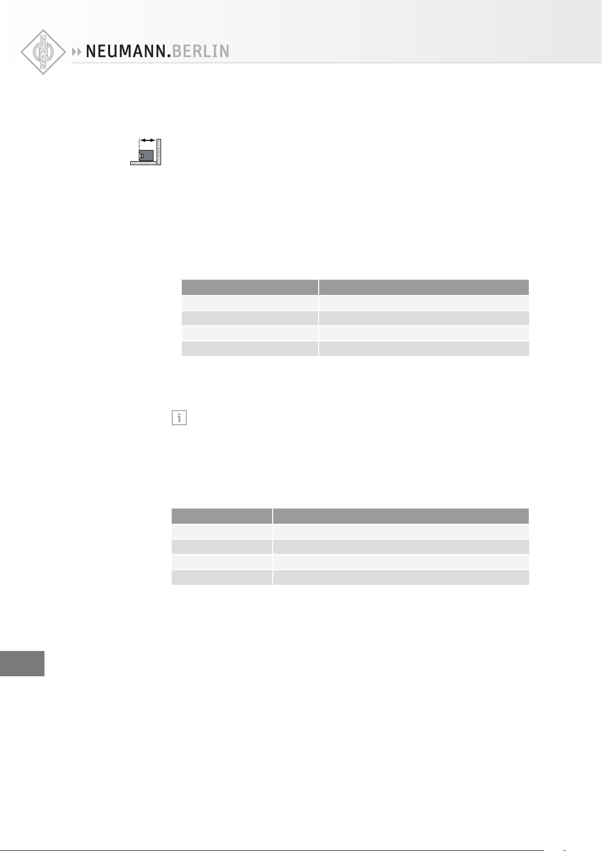
Positioning the subwoofers
Regardless of whether you are setting up one or several subwoofers:
d
wall
X
Always ensure that the distance d
woofer’s front is less than 0.8 m.
between the wall behind the subwoofer and the sub-
wall
If you are setting up one subwoofer:
X
Position the subwoofer against the front wall, slightly left or right of the middle of the front
wall and between the left and right loudspeakers.
If you are setting up several subwoofers as a Plane Wave Bass Array™ (PWBA™):
X
Use two to four subwoofers for smaller rooms and three to four subwoofers for larger rooms.
X
Set up the subwoofers along the front wall within half a wavelength of each other. The maximum spacing of the subwoofer cabinets is determined by the setting of the LFE mode
(see page 20):
Setting Max. spacing of the subwoofer cabinets
LFE → SUB + L/R (>80) approx. 2 m (6'6")
LFE → SUB ONLY (<80) approx. 2 m (6'6")
LFE → SUB ONLY (<120) approx. 1.4 m (4'6")
DIRECT IN → SUB ONLY approx. 1.4 m (4'6")
If you observe the stated spacing, the subwoofers form a cylindrical source and generate
a plane wave down the room, a so-called Plane Wave Bass Array™ (PWBA™). The PWBA™
reduces stationary waves between the side walls, improves the bass reproduction and
suppresses lateral room resonances.
For examples of set up positions and distances, please refer to the supplied “Getting
Started Quickly” supplement.
EN
Utilizing the
acoustical gain
You can correct excessive low frequency energy in the room using the potentiometer
SUBWOOFER GAIN| INPUT GAIN L and the switch SUBWOOFER GAIN | OUTPUT LEVEL K
(cf. page31).
If you set up several subwoofers, you can utilize their mutual coupling to achieve an acoustical
gain. The following acoustical gains are possible:
Number of subwoofers Acoustical gain
1 0.0 dB
2 6.0 dB
3 9.5 dB
4 12.0 dB
Positioning and orienting subwoofers and loudspeakers
Subwoofers are omni-directional in their typical pass band as the generated wavelength is
long compared to the surface producing the sound, therefore it does not matter in which direction the subwoofer is oriented when placed in the listening environment.
10 | KH 810/870
Page 13

For your loudspeakers, however, an accurate positioning and orientation is vital.
Output (RCA)
Input (XLR-M)
X
Position your loudspeakers as follows:
System Position and orientation
2.0 (stereo) ±30°
5.1 ITU-R BS.775-1:
0°, ±30°, ±110° (±10°)
(center, front left/right, surround left/right)
ANSI/SMPTE 202M:
0°, ±22.5°, arrays to the surround left and to the surround right,
plus optional subwoofer(s)
6.1 as 5.1 systems plus 180° (back center)
7.1 0°, ±30°, ±90°, ±150°
(center, front left/right, side left/right, back left/right)
For detailed information on the positioning and orientation of your loudspeakers, please refer
to the operating manuals of the loudspeakers.
If your subwoofers cannot be placed at the same distance from the listening position as the
loudspeakers, time-of-flight dierences will occur.
X
Avoid distance dierences of > 2m (6'6").
X
Compensate for time-of-flight dierences as described in the chapter “Calibrating the phase”
on page 19.
Connecting
unbalanced
cables
Connecting the subwoofer
Connecting the subwoofer to an audio source
X
Use balanced XLR cables to connect the corresponding sockets INPUT 8 of the KH810/870
to the audio source.
X
Use an XLR adapter (not supplied) to connect unbalanced cables (e.g. RCA cables).
following wiring if you want to make your own XLR adapter:
Wiring Pin Signal
1 Audio ground
2 Signal +
3 Signal -
The level delivered by devices with RCA outputs (-10 dBV) is usually less than the studio level
(+4 dBu):
X
If necessary, use active unbalanced-to-balanced converters in order to be able to connect
devices with unbalanced signals.
Use the
EN
KH 810/870 | 11
Page 14

Connecting loudspeakers to the subwoofer
For a simplified representation, the following connection examples show small loudspeakers
in combination with the KH810 subwoofer. Each of the examples only shows one possible
combination of loudspeakers and subwoofers. For information on building a balanced system,
please refer to the “Product Selection Guide” at www.neumann.com. In addition, the subwoofer electronics are shown separately from the KH810 to provide better clarity.
X
Use balanced XLR cables to connect the corresponding sockets OUTPUTA of the subwoofer
to the input sockets of the loudspeakers, as shown in the following diagrams.
Connection of a
7.1 system
7.1 Hig h Definition
.
1 High Definition
7
Bass Manager
Bass Manager
Left /
Right
Rig ht
Center
Center /
Left
LFE
Left Back
Left Surround /
Right Back
Rig ht Surround
Left Surround
Left Back /
Right Surround
Rig ht Back
LFE
Σ
Σ
A
B
A
B
A
B
A
B
Internal Subwoofer Signal or
Driver Cable (DC nn) when Remote
Electronics Kit (REK 3) is used
Sum Output
Sum Output
Rig ht
Right
Left
Center
Center
Left
Left Back
Left Surround
Right Back
Rig ht Surrou
Left Surround
Left Back
Right Surround
Rig ht Back
Optional additional subwoofers
The diagram “Connection of a 7.1 system” also demonstrates that the built-in 7.1 Channel High
Definition Bass Manager™ can be used to build 1.0, 2.0, 3/1.0, 5.0, 5.1, 6.0, 6.1 and 7.1 Theatrical systems.
Internal Subwoofer Signal or
Driver Cable (DC nn) when Remote
Electronics Kit (REK 3) is used
EN
Simultaneous
connections of
5.1 and 2.0 signals
12 | KH 810/870
7
.
1 High Definition
Bass Manager
Right
Center
Left
Left Back
Right Back
Left Surround
Right Surround
LFE
Σ
Sum Output
Right
Center
Left
Left Back
Right Back
Left Surround
Right Surround
Optional additional subwoofers
Page 15

The diagram “Simultaneous connections of 5.1 and 2.0 signals” shows the possibility of an
additional bass extension for a 2.0 signal:
X
First, set up a 5.1 system.
X
Connect a stereo signal to the unused sockets INPUT | LEFT BACK and RIGHT BACK8.
X
Connect an additional pair of loudspeakers to the unused sockets OUTPUT | LEFT BACK and
RIGHT BACKA.
You now have a separate 2.0 system that can use the subwoofer.
X
Send either a 5.1 or a 2.0 signal to the system.
X
Try to keep the two pairs of loudspeakers connected to the sockets INPUT | LEFT/INPUT | LEFT
BACK and INPUT | RIGHT/INPUT | RIGHT BACK at the same distance from the listening position
(see diagram) so that dierent phase settings are not required.
Connecting several KH 810/870
To increase the number of subwoofers in a system and to make a Plane Wave Bass Array™, you
can connect the KH810/870 to additional KH 810/870 subwoofers. In such a set-up, the input
signals are only connected to the first subwoofer in the chain. The LFE mode and bass management is defined in the first subwoofer.
X
Connect your audio source to the sockets INPUT | LEFT/RIGHT BACK, LEFT/RIGHT
SURROUND, LEFT, CENTER and RIGHT 8 and to the socket INPUT | DIRECT IN / LFE / SUM 9
of the first subwoofer.
X
Connect the socket OUTPUT | SUM0 to the analog input socket INPUT | DIRECT IN / LFE /
SUM 9 of another KH 810/870 subwoofer.
X
Set the rotary switch LFE MODE S of all additional subwoofers to “DIRECT IN -> SUB ONLY”.
This prevents double filtering of the audio signal.
X
Make sure that all other settings such as level, phase, EQ, ... are also set on each of the additional subwoofers. This information is not daisy-chained from the first subwoofer (master) to
the additional subwoofers.
7.1 Hig h Definition
Bass Manager
Right
Center
Left
Left Surround
Left Back
Right Back
Right Surround
LFE
Internal Subwoofer Signal or
Driver Cable (DC nn) when Remote
Electronics Kit (REK 2) is used
Sum Output
Σ
Right
Center
Left
Left Surround
Left Back
Right Back
Right Surround
LFE Mode =
LFE -> SUB L/R (> 80) or
LFE -> SUB ONLY (< 80) or
LFE -> SUB ONLY (< 120) or
DIRECT IN -> SUB ONLY
Sum
Input
LFE Mode = DIRECT IN -> SUB ONLY
Sum
Outpu t
Sum
Input
Sum
Outpu t
Sum
Input
Sum
Outpu t
EN
KH 810/870 | 13
Page 16

Using subwoofers in a 4-way system
To build a larger system:
X
Install the subwoofers and loudspeakers like columns:
INPUT INPUT INPUT
OUTPUT LEFT OUTPUT CENTER OUTPUT RIGHT
INPUT LEFT INPUT CENTER INPUT RIGHT
Left
Center
Right
LFE
X
Connect the channels Left, Center, Right of your audio source to the subwoofers according
LFE LFE LFE
to their physical position (see diagram above):
• Connect the channel Left to the socket INPUT | LEFT 8 of the left subwoofer, connect the
channel Center to the socket INPUT | CENTER 8 of the middle subwoofer and connect the
channel Right to the socket INPUT | RIGHT 8 of the right subwoofer.
X
Use a Y-cable (not supplied) to connect the LFE channel of the audio source to the sockets
INPUT | DIRECT IN / LFE /SUM9 of all three subwoofers.
To tilt the loudspeakers, you can use Neumann mounting hardware such as, for example,
the LH 36.
The subwoofers should be acoustically calibrated so that they smoothly extend the bass
response of their respective main loudspeaker. As three subwoofers are being used to reproduce one signal, there is a 9.5 dB acoustical boost for the LFE channel only. The LFE channel
level should be adjusted at the audio source by –9.5 dB or +0.5 dB so that the reproduction
level (0 or +10dB) is consistent with the main channels.
EN
14 | KH 810/870
Page 17

Connecting/disconnecting the subwoofer to/from the mains power supply
To connect the KH 810/870 to the mains power supply:
X
Make sure that the switch MAINS POWER 5 is set to “OFF”.
X
Make sure that the switch MAINS VOLTAGE SELECTION 4 is set to the correct position:
“AC 100/120 V” if your mains voltage is 100 V or 120V or
“AC 220/240 V” if your mains voltage is 220 V, 230 V or 240V.
X
If necessary, carry out further steps for a remote switch-on/switch-o (see below).
X
Connect the IEC connector of the supplied mains cable to the IEC mains socket 7.
AC 220-240 V
MAINS VOLTAGE
SELECTION
AC 100-120 V
4
5
MAINS POWER
OPTIONAL
REMOTE
POWER
ON / OFF
AC 100-120 V /
220-240 V
~ 50-60 Hz
X
Connect the mains plug of the mains cable to a suitable wall socket.
ON
OFF
OPTIONAL
REMOTE
POWER ON/OFF
7
Power Source
To disconnect the KH 810/870 from the mains power supply:
X
Set the switch MAINS POWER 5 to “OFF”.
X
Pull the mains plug out of the wall socket.
Mounting the subwoofer electronics externally
If you distribute the subwoofers around the room but wish to have centralized access to the
operating controls of the subwoofer electronics or if you set up your subwoofers so that easy
access to the subwoofer electronics is not possible, you can mount the latter externally:
X
Use the Neumann REK3 remote electronics kit together with an SC cable (available in dierent lengths, see “Accessories” on page28).
X
Proceed as described in the operating manual of the REK 3.
KH 810/870 | 15
EN
Page 18

OPTIONAL
REMOTE
POWER
ON / OFF
Preparing the subwoofer for remote on/o switching
X
Have your Neumann service partner enable the remote on/o switching function inside the
subwoofer.
X
-
+
Use a Euroblock connector (not supplied) to connect a two-core cable (12 V DC) to the socket
OPTIONAL REMOTE POWER ON/OFF 6 (socket pin assignment shown on the left).
For further information on remotely switching the subwoofer on/o, please refer to
page 17.
Preparing the subwoofer for remote control/RS-232 control
CAUTION
Material damage due to improper use of cables!
If you insert a network cable that is connected to the KH 810/870 into a network socket, the
network device can be damaged. If network signals are transmitted to the KH 810/870 via
a network cable, the KH 810/870 can be damaged.
X
Only connect the KH 810/870 to Neumann remote controls or devices that deliver a RS-232
signal using a high-quality Neumann RC CAT5 cable (see below). Do not use a “crossover”
type of CAT5 cable.
You can remote control the KH 810/870 via the Neumann NRC 1 remote control (see “Accessories” on page 28) or control it via an RS-232 signal. For more information, please refer to
the operating manuals of the remote controls and to page 22.
X
Connect the NRC 1 remote control or the RS-232 control to the socket REMOTE CONTROL AND
RS-232 B. Use Neumann RC cables with Neutrik EtherCon connectors (see “Accessories” on
page28). These cables are available in dierent lengths, have been designed for heavyduty use and provide maximum freedom of movement.
The pin assignment of the socket REMOTE CONTROL AND RS-232 B can be found at the
end of this operating manual.
To remote control more than one subwoofer, an SEA 1 is required (see “Accessories” on
page 28). This device duplicates control signals across multiple subwoofers. For
more information, see the SEA 1 operating manual.
EN
16 | KH 810/870
Page 19

Using the KH 810/870
Switching the subwoofer on/o
You can switch the KH 810/870 on and o using the switch MAINS POWER 5 or remotely.
ON
MAINS POWER
OFF
On/o switching
using the switch
MAINS POWER 5
Remote on/o
switching
OPTIONAL
REMOTE
POWER
ON / OFF
X
Set the switch MAINS POWER 5 to:
OPTIONAL
REMOTE
POWER ON/OFF
• “ON” to switch the subwoofer on. The LED POWER ONE flashes for 3 seconds, during
which the subwoofer is muted (see below). The LED POWER ONE then lights up red.
• “OFF” to switch the subwoofer o. The LED POWER ONE goes o.
There is a three second delay before sound can be heard from the KH 810/870 in order
to avoid noises (pops) from preceding equipment switched on at the same time. Conversely, switching o the subwoofer immediately mutes the audio.
X
Carry out all steps described in the chapter “Preparing the subwoofer for remote on/o
switching” on page 16.
X
Make sure that the switch MAINS POWER 5 is set to “ON”.
X
Apply 12V DC to remotely switch the subwoofer electronics on or apply 0V DC to remotely
switch the subwoofer electronics o.
Calibrating the subwoofer
Before using your system for the first time and whenever you change the physical conditions in
your studio, carry out the following steps:
X
Adjust the frequency response and the level of the loudspeakers before calibrating the subwoofer (see the operating manual of the loudspeakers):
Application Recommended frequency response Commentary
Studio flat
-
Film X-curve shape Cf. ANSI/SMPTE 202M:
the shape of the X-curve
depends on the size of the room
Home subjective evaluation Not necessarily a flat response,
a gently downward sloping
response with increasing
frequency is often preferred
All the loudspeakers in the system should have the same level at the listening position. This
is often measured using a pink noise test signal that is set to -18 dBFS (Europe) or -20 dBFS
(USA) on the mixing console’s output level meters and a sound level meter set to “C-weighted”
and “slow”.
KH 810/870 | 17
EN
Page 20

EN
Calibrating the
frequency
response
0
-12
40 Hz
X
Calibrate the frequency response, the phase and the acoustical level of the subwoofer.
To do so, choose one of the following methods:
1. Calibration using an acoustical measurement system
Calibrating the frequency response, phase and sound pressure level by means of an
acoustical measurement system should always be your first choice since it yields the
highest accuracy. This method is described below.
2. Calibration using Neumann test signals
In the absence of an acoustical measurement system, you can calibrate the settings of
your subwoofer using Neumann test signals (see page 19).
3. Calibration using music signals and an 80 Hz test signal
A calibration by means of music signals is also possible but should always be the last
choice. In this case, use the built-in 80 Hz test signal generator to calibrate the phase
(see page 19).
If you are using several subwoofers, it is possible that the same setting is not valid for all
subwoofers.
X
Calibrate each subwoofer separately.
X
If necessary, move the subwoofer and/or the main loudspeakers.
X
If necessary, apply acoustical treatment to the source of any reflections.
Calibration using an acoustical measurement system
The settings of the potentiometer SUBWOOFER GAIN | INPUT GAIN L recommended in
the following table are valid for the following settings of your Neumann loudspeaker:
INPUT GAIN: “0 dB” and OUTPUT LEVEL: “100 dB SPL at 1m for 0 dBu”. For information
on how to set your Neumann loudspeaker, please refer to its operating manual. If the
mentioned values cannot be set on your loudspeaker, adjust the subwoofer accordingly.
The frequency response of a subwoofer depends on its position in the room and on the room
geometry. The same subwoofer installed in dierent positions in the same room may require
dierent acoustical control settings.
X
Adjust the frequency response of the subwoofer at your listening position. To do so, proceed
as follows:
X
Make sure that the switch SUBWOOFER GAIN | OUTPUT LEVEL K is set to “100 dB SPL at 1m
for 0 dBu”.
X
First, set the potentiometers SUBWOOFER GAIN | INPUT GAIN L and LOW CUT Q to the
following settings. These settings can be used as a starting point for further adjustment:
Subwoofer position Setting of potentiometer
SUBWOOFER GAIN | INPUT GAIN L
In a corner -8 dB -4 dB
Next to or flush
-4 dB -2 dB
mounted in an
acoustically solid
wall (e.g. brick,
concrete)
Next to or flush
-2 dB 0 dB
mounted in an
acoustically soft
wall (e.g. gypsum)
Free standing in an
-2 dB 0 dB
untreated room
Free standing in a
0 dB 0 dB
well-treated room
Setting of potentiometer
LOW CUT Q
18 | KH 810/870
Page 21

X
Check the frequency response at the listening position using your acoustical measurement
system:
• In case of acoustical loading in the low frequency range at the listening position, turn
the potentiometer LOW CUT Q to the left. This reduces the output level of the subwoofer
towards lower frequencies.
• Use the parametric equalizer P to compensate for further nonlinearities in the frequency
response below 120 Hz caused by room modes.
Calibrating the
subwoofer level
Calibrating the
phase
X
Measure the subwoofer’s sound pressure level at the listening position.
X
Adjust the sound pressure level of the subwoofer so that the level of the frequency response
of the subwoofer below 80 Hz corresponds to the level of the frequency response of the
loudspeakers above 80 Hz.
• To do so, use the potentiometer SUBWOOFER GAIN | INPUT GAIN L and the switch
S UBWOOFER GAIN | OUTPUT LEVEL K. Make sure that the input signal is not too high.
X
Set the phase using the rotary switch SUBWOOFER PHASE N. Values from -180º to -315
can be obtained by setting the switch SUBWOOFER PHASE M to “–180º” and by adding the
set value of the rotary switch SUBWOOFER PHASE N.
Example: To obtain a phase shift of –270º, set the switch SUBWOOFER PHASE M to “–180º”
and the rotary switch SUBWOOFER PHASE N to “–90º”
X
Set the rotary switch SUBWOOFER PHASE N in combination with the switch SUBWOOFER
PHASE M to values of 0º, -45º, -90º, -135º, -180º, -225º, -270º, and -315º, until you have
found the setting that gives the lowest sound pressure level at the listening position at the
cut-o frequency of 80 Hz (180º phase shift between subwoofer and loudspeaker, maximum
level cancelation).
X
Set the switch SUBWOOFER PHASE to the opposite position. The phase shift between
loudspeaker and subwoofer is now 0º. Check your subwoofer’s sound pressure level again
and, if necessary, readjust it so that it corresponds to the sound pressure level of the
l oudspeakers.
Your system is now completely acoustically calibrated.
Calibration using Neumann test signals
X
Download the Neumann test signals and the instructions for use (PDF file, in English) from
the KH 810/870 product page at www.neumann.com.
X
Follow the steps described there.
º
Calibration using music signals and an 80 Hz test signal
X
Adjust the settings for the sound pressure level and the frequency response as described
above.
X
Calibrate the acoustical phase using the built-in 80 Hz test signal generator. Check the settings of the sound pressure level and frequency response by means of music signals you are
familiar with.
• Connect the left front loudspeaker to the socket OUTPUT | LEFT A.
• Set the switch BASS MANAGEMENT G to “BASS MANAGEMENT”.
• Set the switch TEST SIGNAL J to “ON”.
An 80 Hz test signal is internally applied to the audio input INPUT | LEFT 8 and is reproduced at the socket OUTPUT | LEFT A and by the subwoofer.
• Set the rotary switch SUBWOOFER PHASE N in combination with the switch SUBWOOFER
PHASE M to values of 0
º
, -45º, -90º, -135º, -180º, -225º, -270º, and -315º, until you
EN
have found the setting that gives the lowest sound pressure level at the listening position
at the cut-o frequency of 80 Hz (180º phase shift between subwoofer and loudspeaker,
maximum level cancelation).
• Set the switch TEST SIGNAL J to “OFF”.
• Set the switch SUBWOOFER PHASE M to the opposite position.
The phase shift between loudspeaker and subwoofer is now 0
º
.
KH 810/870 | 19
Page 22

Compensating for
TOF dierences by
means of an
electronic time
delay
X
Check the settings of the sound pressure level and frequency response by means of music
signals. Listen for a smooth extension of the frequency response of the main loudspeakers
down to 20 Hz.
To to this, proceed as follows:
X
Listen to music containing content down to 20 Hz. Activate and disable the bass management
by repeatedly moving the switch BASS MANAGEMENTG between the two positions. There
should be no increase or decrease in level below 80 Hz.
Compensating for larger time of flight (TOF) dierences
If the subwoofer is placed at a distance > 2 m (6'6") behind the loudspeakers with reference to
the listening position, the subwoofer’s integrated compensation settings will not suce.
X
Connect the KH810/870 to an electronic time delay. Insert the electronic time delay into the
signal path between the sockets OUTPUT A of the subwoofer and the input sockets of the
loudspeakers.
X
Compensate for TOF dierences using the electronic time delay (see the operating instructions of the delay).
Using the bass management
X
Set the switch BASS MANAGEMENT G to “BASS MANAGEMENT”.
The bass management is activated. This inserts a 4th order 80 Hz high pass filter into the
signal path of the audio outputs OUTPUT | LEFT, CENTER, RIGHT, LEFT/RIGHT SURROUND and
LEFT/RIGHT BACK and routes all audio signals below 80 Hz to the subwoofer. The LED BASS
MANAGEMENT F lights up green.
To exclude the audio channels OUTPUT | LEFT/RIGHT BACK and OUTPUT | LEFT/RIGHT SURROUND from the bass management:
X
Set the switch REAR CH BASS MANAGEMENT H to “DISABLE”.
EN
Using the LFE
10 dB gain
If you set the switch BASS MANAGEMENT G to “DISABLE”, this also deactivates the
bass management of the audio outputs OUTPUT | LEFT/RIGHT BACK.
If you deactivate the bass management, the audio signal of the audio outputs OUTPUT | LEFT,
CENTER, RIGHT, LEFT/RIGHT SURROUND and LEFT/RIGHT BACK is only reproduced by the
loudspeakers, while the subwoofer only reproduces the signal of the LFE channel. Use this
function to prevent the low frequency signal components of the main channels being reproduced by the subwoofer.
X
Set the switch BASS MANAGEMENT G to “DISABLE”.
Boosting the LFE channel and adjusting the LFE mode
If you are using three subwoofers in a 4-way system (see page 14), the acoustical
level of the LFE signal is boosted by 9.5 dB. In this case, it is sucient to increase the
level of the audio source by 0.5 dB to obtain an LFE gain of 10 dB.
You can boost the level of the LFE channel by 10 dB. This boost can be performed in the monitoring matrix (console or external), in a decoder output stage (surround sound processor or
DVD/Blu-ray disk player), or in the 7.1 High Definition Bass Management System of the
KH810/870.
X
First, check if a 10 dB gain has already been applied somewhere else in the signal path.
If this is the case:
X
Make sure that the switch LFE GAIN R is set to “0 dB”.
20 | KH 810/870
Page 23

If the boost of the LFE channel is to be performed in the 7.1 Channel High Definition Bass
Management System of your subwoofer:
X
Make sure that the rotary switch LFE MODE S is not set to “DIRECT IN -> SUB ONLY”.
Set the switch LFE GAIN R to “ + 10 dB”.
Adjusting the
LFE mode
The following settings only apply to the audio input INPUT | DIRECT IN / LFE /SUM 9.
X
Set the rotary switch LFE MODE S to the desired position:
1. LFE → SUB + L/R (>80)
2. LFE → SUB ONLY (<80)
3. LFE → SUB ONLY (<120)
4. DIRECT IN → SUB ONLY
20 Hz 80 Hz 120 Hz
L/R at
−6 dB
Setting Behavior of the subwoofer
LFE → SUB + L/R (> 80) Up to 80 Hz, the LFE channel is reproduced by the sub-
woofer. Above 80 Hz, the LFE channel is routed to the audio
outputs OUTPUT | LEFT and RIGHT.
To compensate for a 6 dB acoustical gain when reproducing
the signal via the audio outputs OUTPUT | LEFT and RIGHT,
a 6 dB electrical attenuation is applied. This mode works
with all formats and is consistent with the standard
downmix coecients seen in consumer decoders.
Additionally, this mode is useful for detecting higher frequency signals in the LFE channel that should be avoided
during mixing.
LFE → SUB ONLY (< 80) The LFE channel is reproduced up to 80 Hz in the subwoofer
only. This setting comes from a recommendation by Dolby
and THX to “pre-filter” the LFE channel and is used to simulate consumer decoders that do not reproduce the upper
part of the LFE bandwidth.
LFE → SUB ONLY (< 120) The LFE channel is reproduced up to 120 Hz in the subwoofer
only. This is the norm for the movie industry. Please note
that, during mixing, unwanted higher frequency signal
components (above 120 Hz) in the LFE channel are not
reproduced by the subwoofer.
DIRECT IN → SUB ONLY The LFE channel is reproduced by the subwoofer only. There
is no filtering of the LFE channel. Select this setting if you
want to daisy-chain additional subwoofers (see page 13)
and if an external bass management is used (e.g. surround
sound processors or DVD/Blu-ray disk players; the output
is often labeled “Subwoofer”).
Additionally, this mode is useful for detecting higher
frequency signal components (up to 300 Hz) in the
LFE channel that should be avoided during mixing.
Please note that the LFE gain is always 0 dB in this mode.
EN
KH 810/870 | 21
Page 24

INPUT
GROUND LIFT
PIN 1 CONNECTED
Using the NRC 1
remote control
Activating ground lift
If there is humming or buzzing noise coming from the subwoofer, first search for the cause of
the noise:
X
Disconnect all input and output signal cables from the subwoofer.
If the noise goes away, it is probably coming from the audio source or source cabling. It might
be possible to eliminate the noise by disconnecting the ground from the input signals
(activating ground lift).
To activate ground lift:
X
Reconnect the signal cables and set the switch INPUT GROUND LIFTC to “INPUT GROUND
LIFT”.
This internally disconnects pin 1 of all 8 XLR sockets from the subwoofer electronics’ chassis
ground (see table on page 11).
For safety reasons, the electronics chassis ground is always connected to the mains
power earth pin.
Even when ground lift is activated, the pins 1 of all audio inputs remain electronically
connected to each each other.
Remote-controlling the system
Using a Neumann NRC 1 remote control (see page 16), you can remote control the following
parameters:
• Adjustment of the system output level (level of the subwoofer and level of the signals available at the output sockets OUTPUT | LEFT, CENTER, RIGHT, LEFT/RIGHT SURROUND & LEFT/
RIGHT BACK A, see the section “Activating/deactivating the remote control for the level
controls” on page 23)
• Activation/deactivation of the bass management (see page 20)
• 0 dB/+10 dB gain of the LFE channel (see page 20)
EN
Using a RS-232
data link
For information on the use of an NRC 1 remote control, please refer to its operating manual.
Note that no audio passes down the remote control cables, only control signals and
data.
Using a RS-232 data link, you can remote control additional parameters of the subwoofer:
• Muting of all and/or individual channels
• Level control of individual channels
• Activation/deactivation of the bass management and rear bass management (see page20)
• Activation/deactivation of the LFE channel gain (see page 20)
• Resetting of settings of the KH 810/870 (see page 23)
In addition, using a RS-232 data link, you can read out the following parameters:
• Muting of each channel
• Level of each channel
• Firmware revision
The PDF file “7.1_bass_manager_control_protocol” contains a list of the RS-232 commands that can be used to control the KH 810/870, and it can be downloaded from the
KH810/870 product page at www.neumann.com.
22 | KH 810/870
Page 25

Activating/deactivating the remote control for the level controls
WARNING
Danger of hearing damage due to sudden high sound pressure levels!
If – with an audio signal present – you remove the Neumann NRC 1 remote control while the
switch VOLUME CONTROL I is set to “VOLUME CONTROL” or you set the switch VOLUME CONTROL I to “DISABLE” while the Neumann NRC 1 remote control is connected, the system output
level is immediately set to 0 dB. This can create sudden, very high sound pressure levels which
can damage your hearing.
X
Always lower the output level of the audio source before removing a connected Neumann NRC 1
remote control or – with the remote control connected – setting the switch VOLUME CONTROL
to “DISABLE”.
To be able to use the remote control for adjusting the level controls, you have to activate this
function:
X
Set the switch VOLUME CONTROL I to “ACTIVE”.
You can now remote control the system output level.
To deactivate the remote control for the level controls or to remove the remote control cable from the
socket REMOTE CONTROL AND RS-232B:
If you are using the Neumann NRC 1 remote control:
X
First, make sure that no high-level audio signals are present.
X
Set the switch VOLUME VOLUME CONTROL I to “DISABLE”.
The system output level is automatically reset to 0 dB and you can now remove the remote control
cable from the socket REMOTE CONTROL AND RS-232B.
If you are using an RS-232 control:
X
Remove the cable of the RS-232 control from the socket REMOTE CONTROL AND RS-232B.
The system output level continues at the level value last send to the subwoofer.
To reset the system output level to 0 dB:
X
Switch the subwoofer o and on again.
or
X
Set the switch VOLUME CONTROL I to “DISABLE”.
KH 810/870 | 23
EN
Page 26

Resetting the settings of the KH 810/870
If you control the KH 810/870 using the RS-232 protocol, you can change ...
• settings that you cannot make using the switches on the rear of the KH 810/870;
• settings that deviate from the actual position of the switches of the KH 810/870.
To reset the KH 810/870 to the factory default settings or to reset the settings of the switches on the rear of the
subwoofer:
X
Switch the subwoofer o and on again by setting the switch MAINS POWER5 to “OFF” and then to “ON”.
X
Within 5 seconds after switch-on, move the switch REAR CH BASS MANAGEMENT H at least three times to the
left and right.
If resetting was successful, the LEDs POWER ON E and BASS MANAGEMENT F alternately flash for approx. 2 seconds
and the subwoofer then restarts.
The following settings are reset:
Setting Factory default setting
Output level of the subwoofer Setting of the switch
SUBWOOFER GAIN | OUTPUT LEVEL K
Level of all or individual signals at
the sockets OUTPUT | LEFT/RIGHT
BACK, LEFT/RIGHT SURROUND, LEFT,
CENTER & RIGHT A
Muting of all and/or individual channels No muting
Activation/deactivation of the bass
management
Activation/deactivation of the
rear channel bass management
Gain of the LFE channel
0 dB
Setting of the switch
BASS MANAGEMENT G
Setting of the switch
REAR CH BASS MANAGEMENT H
Setting of the switch LFE GAIN R
EN
24 | KH 810/870
Page 27

Cleaning and maintaining the subwoofer
CAUTION
Damage to the product caused by liquids!
Liquids entering the product can cause a short-circuit in the electronics and damage or even destroy the product.
X
Keep all liquids away from the product.
X
Before cleaning, disconnect the product from the mains power supply (see page15).
X
Use a soft, dry, and lint-free cloth to clean the product.
Troubleshooting
Problem Cause Solution
There is hum or buzz coming
from the KH 810/870 when an
audio cable is connected.
The bass management of the
audio outputs OUTPUT | LEFT/
RIGHT BACKA does not seem
to work, even though the
switch REAR CH BASS MANAGEMENT H is set to the left.
There is a sudden reduction
of the subwoofer’s output
level, the LED POWER ON E
flashes slowly, the output
level is reduced by 6 dB.
The level controls on the rear
of the subwoofer behave
dierent than expected.
The LED POWER ON E goes
o in time with high-energy,
low-frequency signals.
For further information, please refer to the “Questions & Answers” section at www.neumann.com.
A cable is defective, the cabling is
bad, there is ground loop in the installation or the level of the audio source
is too low.
The switch BASS MANAGEMENT G is
set to “DISABLE”. This also deactivates
the bass management of the audio
outputs OUTPUT | LEFT/RIGHT BACK A.
The temperature of the power amplifier is too high.
The values of the switches have been
changed by the remote control for the
level controls.
The signal level is too high,
the protection system is active.
Check all cabling to eliminate the
cause of the problem, use balanced cables, use the ground lift
switch (see page 22) or send
higher signal levels from your
source and reduce the level on
your subwoofer and your monitors.
Set the switch BASS MANAGEMENT
G to “BASS MANAGEMENT”.
Ensure sucient ventilation of
the subwoofer and/or reduce the
input signal level, or add extra
subwoofers to increase LF headroom. When the temperature has
dropped again, the LED POWER ON
E lights up constantly and the
output level reduction is canceled.
Deactivate the remote control for
the level controls. To do so, read
and follow the instructions and
warning notes on page23.
If necessary, reset the settings of
the KH 810/870 (see page 23).
Reduce the signal level.
KH 810/870 | 25
EN
Page 28

Specifications
Acoustics
-3 dB free field frequency response 18 Hz to 300 Hz, ±3 dB
Pass band free field frequency response 19 Hz to 300 Hz, ±2 dB
Self-generated noise
(with input gain set to 100 dB for 0 dBu)
Total harmonic distortion < 0.5 % at 95 dB SPL at 1 m >40 Hz >45 Hz
Max. SPL in half space with 3% THD at 1 m,
averaged between 40 Hz and 90 Hz
Max. SPL with pink noise in half space at 1 m, linear 118 dB SPL 112 dB SPL
Electronics
Amplifier, continuous (peak) output power 320 W (400 W) 160 W (200 W)
THD and noise at continuous load < 0.1 % (-60 dB) with deactivated limiter
Controller design analog, active
Crossover frequency of main channels 80 Hz
Crossover slope 24 dB/oct., 4
Acoustical control | Low cut center frequency: 30 Hz
Acoustical control | Parametric equalizer bypassable
Time of flight adjustment delay
Volume control 100 dB SPL, 114 dB SPL
Input sensitivity -12 dB ... +2 dB
Calibration tools internal signal generator
Protection circuitry peak and thermal limiters
Infrasonic filter frequency; slope 6.5 Hz; 12 dB/oct.
Remote control via cable remote control and RS-232
KH 870 KH810
< 20 dB(A) at 10 cm
116.7 dB SPL 110.7 dB SPL
KH 870 KH810
th
order
Q factor = 1.5
gain range: 0 to -12 dB
gain: +4 to -12 dB
frequency: 20 Hz to 120 Hz
Q factor: 1 to 8
º
0
to -315º, adjustable in steps of 45
º
EN
Analog inputs and outputs
Input/output channels 7.1 / 7+Sum
Impedance, electrically balanced XLR, 13 kΩ
Input sensitivity -8 dBu/ +6 dBu (switchable)
CMRR of inputs >60 dB at 15 kHz
Max. input level +19 dBu (6.9 V)
Cross-talk between channels (1 kHz) < -95 dB
Level matching ±0.1 dB
Volume control range
(via remote control)
Dynamic range, THD+N 119 dB(A), < 0.001% at -100 dB
LFE modes 80 +re-routing, 80, 120, fullrange
LFE gain 0 dB / +10 dB (switchable)
Gain control +2 … -12 dB
118 dB,
0.25 dB steps
26 | KH 810/870
Page 29

Displays
Switch-on indicator red LED lights up (and remote control logo)
Limit/clip red LED “flashing” (and remote control logo)
Bass management active green LED lights up
KH 870 KH810
Product properties
Mains voltage 220 … 240 or 100 … 120 V AC switchable,
Power consumption (idle) 25 W 20 W
Power consumption (full output AC) 550 W 290 W
Dimensions (H x W x D) 735 x 330 x 645 mm 360 x 330 x 645 mm
Internal net volume/external volume 86.0 l/156.0 l 41.5 l/76.6 l
Weight 47.1 kg (103.6 lbs) 26.0 kg (57.2 lbs)
Driver(s) magnetically shielded
Mounting points mounting flange
Cabinet surface finish, color painted wood (MDF),
Driver protection metal grille
Operating conditions
Ambient temperature +10°C to +40°C (+50°F to +104°F)
Relative humidity max. 90% (non-condensing)
Transport/storage conditions
Ambient temperature –25°C to +70°C (–13°F to +158°F)
Relative humidity max. 90 % (non-condensing)
KH 870 KH810
50/60 Hz
2 x 265 mm (2 x 10")
(∅ 38 mm/1.5") on
upper side
anthracite (RAL 7021)
magnetically shielded
1 x 265 mm (1 x 10")
–
In compliance with
Europe
USA 47 CFR 15 subpart B
Canada ICES-003
EMC EN 55103-1/-2,
Electromagnetic Environment: Class E4
Safety EN 60065
Acoustical measurements, block diagram and pin assignment
Additional technical data such as acoustical measurements, a block diagram of the KH 810/870 and the pin assignments of the XLR socket and the REMOTE CONTROL AND RS-232 socket B can be found at the end of this operating
manual.
EN
KH 810/870 | 27
Page 30

Accessories
Product Description
FO 810 Flight case for KH 810
FO 870 Flight case for KH 870
RC 2 Remote control cable, 2 m
RC 5 Remote control cable, 5 m
RC 10 Remote control cable, 10 m
RC 15 Remote control cable, 15 m
RC 20 Remote control cable, 20 m
RC 25 Remote control cable, 25 m
RC 30 Remote control cable, 30 m
REK3 Remote electronics kit
SC 2 Subwoofer cable, 2 m
SC 5 Subwoofer cable, 5 m
SC 10 Subwoofer cable, 10 m
SC 15 Subwoofer cable, 15 m
SC 20 Subwoofer cable, 20 m
SC 25 Subwoofer cable, 25 m
SC 30 Subwoofer cable, 30 m
SEA 1 Subwoofer EtherCon adapter
NRC 1 Subwoofer remote control
EN
Some hardware for mounting loudspeakers on top of KH 870 subwoofers is also available. For
further information and the complete range of Neumann mounting hardware parts and how
they can be used, refer to the PDF file “Hardware Mounting Matrix” that can be downloaded
from www.neumann.com. Detailed mechanical drawings of the Neumann products are also
available there.
28 | KH 810/870
Page 31

Manufacturer Declarations
Guarantee
For the current terms and conditions of the product guarantee, please visit www.neumann.com.
In compliance with the following requirements
• WEEE (2002/96/EC)
Please dispose of the product at the end of its operational lifetime by taking it to your local
collection point or recycling center for such equipment.
CE Declaration of Conformity
• RoHS (2011/65/EU)
• Low Voltage Directive (2006/95/EC)
• EMC Directive (2004/108/EC)
The declaration is available on the product page at www.neumann.com.
Certified by
Audio, Video and Similar Electronic Apparatus - Safety Requirements CAN/CSA C22.2 No.
60065-03 Incl. AM1 and UL Std. No. 60065-2007
Trademarks
Neumann® is a registered trademark of Georg Neumann GmbH. The following are trademarks
of Georg Neumann GmbH:
• Plane Wave Bass Array™ and PWBA™
Other company, product, or service names mentioned in this operating manual may be the
trademarks, service marks, or registered trademarks of their respective owners.
FCC
This device complies with Part 15 of the FCC Rules. Operation is subject to the following two
conditions: (1) this device may not cause harmful interference, and (2) this device must accept
any interference received, including interference that may cause undesired operation.
This class B digital apparatus complies with the Canadian ICES-003.
Changes or modifications made to this equipment not expressly approved by Neumann may
void the FCC authorization to operate this equipment.
EN
KH 810/870 | 29
Page 32

Technical information & glossary
Absolute
level
In Europe, the absolute level of 0 dBu is -18 dBFS (EBU standard R68). In the US, +4 dBu is -20 dBFS
(SMPTE standard RP155). These dBu values should lead to the following sound pressure levels:
Application Sound pressure level
Film 85 dB(C)
Broadcast 79 dB(C) (reference level)
Music No defined reference levels
Near field loudspeakers can be as close as 1 m from the listening position, whereas loudspeakers in
a Dolby certified movie mixing room should be at least 5 m from the listening position.
In the examples below, it is assumed that the listener is inside the room radius and thus the sound
field decays according to 20log
Absolute voltage level of input signal
Setting SUBWOOFER GAIN | INPUT GAIN L
SettingSUBWOOFER GAIN | OUTPUT LEVEL K
Listening distance [m] (dB change) 5 m (-14 dB) 5 m (-14 dB)
Measured output level in dB SPL at 1 m 85 dB SPL 85 dB SPL
Maximum input signal before activation
of the protection system
Absolute acoustic level calibration for signal channels is generally achieved using a sound level meter
set to “C-weighted” and “Slow”. Play a broadband pink noise test signal set to -18 dBFS (Europe) or
-20 dBFS (USA) on the console meters and measure the sound pressure level at the listening position. Then adjust each channel’s source level, not the loudspeakers and subwoofer(s) so that the
above stated sound pressure levels are achieved.
(r), however this may not always be the case.
10
0 dBu
(0.775 V)
-1 dB -5 dB
100 100
17 dBu 17 dBu
+4 dBu
(1.23 V)
EN
Acoustical
axis
Acoustical
controls
The acoustical axis is a line perpendicular to the subwoofer’s front panel along which the microphone
was placed when tuning the subwoofer’s crossover during design. The acoustical axis is located at the
midpoint of the KH 810’s bass driver or at the midpoint of the bass drivers of the KH 870.
The acoustical controls are low-order analog filters designed to compensate for some of the acoustical
issues commonly found in listening environments. The acoustical controls’ settings will depend on
the subwoofer’s location and will probably be dierent for the same subwoofer type positioned in different locations in the same room. When calibrating subwoofers there are three areas requiring attention: in-room response, level relative to main loudspeakers, and phase relative to main loudspeakers.
30 | KH 810/870
Page 33

Acoustical
output level
Depending on the setting of the potentiometer SUBWOOFER GAIN | INPUT GAIN L and the switch
SUBWOOFER GAIN | OUTPUT LEVEL K — and referred to an input signal level of 0 dBu — the following
acoustical output levels can be obtained:
Setting of potentiometer
SUBWOOFER GAIN |
INPUT GAIN L
-12 dB 88 dB SPL 102 dB SPL
-10 dB 90 dB SPL 104 dB SPL
-8 dB 92 dB SPL 106 dB SPL
-6 dB 94 dB SPL 108 dB SPL
-4 dB 96 dB SPL 110 dB SPL
-2 dB 98 dB SPL 112 dB SPL
0 dB 100 dB SPL 114 dB SPL
+2 dB 102 dB SPL 116 dB SPL
The default setting is SUBWOOFER GAIN | INPUT GAIN L = “0 dB” and SUBWOOFER GAIN | OUTPUT
LEVEL K = “100 dB SPL at 1 m”, which corresponds to a sound pressure level of 100dB SPL measured at a distance of 1 m, when the input signal has a level of 0 dBu.
Using the potentiometer SUBWOOFER GAIN | INPUT GAIN L and the switch SUBWOOFER GAIN |
OUTPUT LEVEL K, you can compensate for level dierences due to acoustical loading (see page 10)
and due to dierent distances of the subwoofers and loudspeakers from the listening position.
Examples of how to calculate sound pressure levels as a function of the input signal levels and input
and output levels of the KH810/870:
Acoustic output level [dB SPL] of the subwoofer at 1 m
when input signal level is 0 dBu
Setting of switch
SUBWOOFER GAIN | OUTPUT
LEVEL K = 100 dB
Setting of switch
SUBWOOFER GAIN | OUTPUT
LEVEL K = 114 dB
Acoustical
response
Absolute voltage level of
input signal
Setting SUBWOOFER GAIN |
INPUT GAIN L
SettingSUBWOOFER GAIN |
OUTPUT LEVEL K
Measured output level in dB
SPL at 1 m
Neumann subwoofers are designed to have a flat pass band magnitude response in anechoic conditions when all the acoustical controls are set to 0 dB. When a subwoofer is installed into a listening
environment the response changes and thus should be corrected back to a flat response. It is therefore expected that the acoustical controls will need adjustment to improve the in-situ response of the
subwoofer. The acoustical controls’ settings depend on the subwoofer’s location and will probably be
dierent for the same subwoofer type installed in dierent locations in the same room. Moving the
cabinet small distances, 50 cm (20”), can dramatically change the response therefore resulting in
dierent acoustical control settings.
Graphs of acoustical measurements conducted in anechoic conditions at a distance 1 m can be found
at the end of this operating manual. Color versions of these graphs can be found on the corresponding
product pages at www.neumann.com.
0 dBu
(0.775 V)
0 0 0 0
100 100 100 100
100 104 106 116
+4 dBu
(1.23 V)
+6 dBu
(1.55 V)
+16 dBu
(4.89 V)
EN
KH 810/870 | 31
Page 34

Analog
output card
Crossover Using 4
Driver(s) Long throw, ecient, low distortion drivers ensure a clean sound quality even at high replay levels.
LFE channel “Low Frequency Eects” (Dolby) or “Low Frequency Enhancement” (dts). The LFE channel has a lim-
The analog output card has seven channels of 4th order 80 Hz high pass filtering and a level control
for each of these channels. Following this, there are seven electronically balanced output stages,
whose signal is present at the sockets OUTPUT | LEFT/RIGHT BACK, LEFT/RIGHT SURROUND, LEFT,
CENTER and RIGHT. All outputs (main channels and sum) have protective circuits to avoid power on/
o noises: the outputs switch on after a short delay when mains power is applied and mute instantaneously when mains power is removed.
If you select the corresponding mode, there is also 80 Hz high pass filtering and summing of the LFE
channel to the left and right outputs (more details can be found in the section “Boosting the LFE channel and adjusting the LFE mode” on page 20).
The socket OUTPUT | SUM 0 allows you to connect additional subwoofers. There is no volume control
on this output as volume control is performed locally in each subwoofer.
th
order filters, the crossover divides the input signal of each channel into two bands for reproduction by the subwoofer or the main loudspeakers. The crossover frequency is fixed at 80 Hz for all
the main channels and can be bypassed when required. This frequency was chosen to balance the
conflicting requirements of having a high crossover frequency to relieve the main loudspeakers of of
their low frequency duties thereby reducing distortion, and of the need to have a low crossover frequency to minimize the chances of localizing the subwoofer thereby giving greater flexibility when
placing the subwoofer in the room. In addition, by choosing 80 Hz, there is a compatibility with the
replay conditions commonly found in consumer products.
The drivers are loaded by the internal volume of the cabinet and are magnetically shielded for use
next to CRT screens and magnetic storage media.
ited bandwidth. Because of the limited frequency range of the LFE channel, it is referred to as “.1”
when describing, for example, a 5.1 system. The designation “LFE channel” always refers to the source
and not to the loudspeakers.
EN
Power
amplifier(s)
Protection
system
Remote
switch-on/
switch-o
The high eciency power amplifiers of the KH 810/870 minimize power dissipation and are run in
bridged mode to minimize distortion.
An extensive protection system prevents damage to the subwoofer if high signal levels are applied to
the input. The LED POWER ON E flashes when the protection system is active. In this case, reduce the
input signal level. If this happens regularly, use a larger subwoofer with a higher SPL output or add
more subwoofers to the system to increase the LF headroom.
The protection system consists of thermal and peak limiters for the amplifier(s) and thermal modeling
of the driver(s). The protection system is not a compressor, it is designed to protect the subwoofer
from damage. The protection system cannot protect against sustained abuse of the loudspeaker system, i.e. playing the subwoofer for long periods of time with the LED POWER ONE flashing. Please
avoid consistent abuse of the subwoofer to not aect the long service life of the product.
A 12 V DC trigger voltage allows you to remotely switch the subwoofer on and o without having to
use the switch MAINS POWER 5. This can be useful in a large installation where the whole room is
powered up using a single switch. The devices are switched on using a time-delay to prevent high
starting current peaks. The trigger voltage switches the subwoofer’s electronics completely on and
o, so the startup time is subject to the same on/o muting delays as if the subwoofer had been
switched on and o using the switch MAINS POWER 5.
32 | KH 810/870
Page 35

RS-232
control
If the control equipment outputs RS-232 data on D-sub connectors, an RS-232 to CAT5 cable is
required. Only pins 3, 4 and 5 should be connected. Pins 4 and 5 should be crossed over, i.e. TX connects to RX and vice versa.
Volume
control
9
6
5
1
D-Sub Pin CAT-5 Pin
2 (RX) 4 (TX)
3 (TX) 5 (RX)
5 (GND) 3 (GND)
Do not connect shield
1
8
RS-232 D-sub to CAT5 adapter
If the control equipment has a USB connector, for example a computer, a USB to RS-232 adapter is
required – these are available from most large computer shops. Once the USB is converted to RS-232,
an RS-232 to CAT5 adapter is required to connect to the subwoofer (see diagram above). Only connect
the three pins indicated in the diagram otherwise damage may occur to the USB to RS-232 adapter.
The VOL stages are located at the main channel outputs of the 7.1 High Definition Bass Manager™ and
the subwoofer output. As a result, they can be used for controlling the replay level of the entire system or for remotely trimming individual loudspeaker levels.
Consequently, they cannot be used to replicate signal SOLO or SELECT type functions as seen in mixing consoles. However, it is possible to MUTE and SOLO one or more of the loudspeaker outputs using
an RS-232 control.
This is useful when setting up the system – play some bass-heavy material at high levels with all the
main loudspeakers muted (subwoofer is soloed) to find the source of rattles in the listening room.
Using subwoofer mute and bass management together gives some useful additional functionality:
Bass management Subwoofer Bass extension (-3 dB)
ON ON 18 Hz
ON MUTED 80 Hz
DISABLE ON Main loudspeaker’s LF cut-o
DISABLE MUTED Main loudspeaker’s LF cut-o
KH 810/870 | 33
EN
Page 36

Page 37

System block diagram/System-Blockdiagramm/
Synoptiquesystème/Diagrama de bloques del sistema
VOL
LEFT BACK
80
LEFT BACK
RIGHT BACK
LEFT
SURROUND
RIGHT
SURROUND
LEFT
RIGHT
CENTER
DIRECT IN
LFE / SUM
Signal
Σ
Generator
LFE Roung
and Gain
Note: +10 dB LFE Gain setting has no eect when LFE MODE switch is set to “DIRECT IN -> SUB ONLY“
VOL
80
VOL
80
VOL
80
Σ
VOL
80
Σ
VOL
80
VOL
80
80
RIGHT BACK
LEFT
SURROUND
RIGHT
SURROUND
Σ
LEFT
RIGHT
CENTER
Power
on Mute
Power
SUM
Σ
80
120
0 … -12 +4 20 1
Low Cut PhaseParametric
-12 120 8
90 135
0 45
180
VOL
Fine
Output
Level
Coarse
Protect
Limiter /
So Clip
Power
Amps
Pin assignment of the XLR socket/Buchsenbelegung XLR/
Brochage de la prise XLR/Asignación de la hembra XLR
1 Audio ground/Audio-Erdung/Masse audio/Toma de tierra de audio
2 Signal +/Signal +/Signal +/Señal +
3 Signal −/Signal −/Signal −/Señal −
Pin assignment of the REMOTE CONTROL AND RS-232
socket/Anschlussbelegung der Buchse REMOTE CONTROL
AND RS-232/Brochage de la prise REMOTE CONTROL AND
RS-232/Asignatión de conexiones de la hembra REMOTE
CONTROL AND RS-232
Function/Funktion/Fonc-
tion/Función
Volume control 1
LOGO voltage 2
*
GND
RS 232 TX
RS 232 RX
*
*
Supply voltage +3.3 V 6
Bypass bass management 7
+10 dB LFE gain 8
*
RS-232 data connection
RJ-45 pins/Buchsenbelegung der RJ-45 Pole/Cablage des
broches RJ-45/Asignación de las hembras de los polos RJ-45
3
4
5
KH 810/870 | I
EN
DE
FR
ES
Page 38

EN The PDF file “7.1 High Definition Bass Manager Remote Control Wiring Diagram”
contains a wiring diagram for making your own hardware remote control for the
KH810/870. You can download it from the KH 810/870 product page at
www.neumann.com.
DE In der PDF-Datei „7.1 High Definition Bass Manager Remote Control Wiring Dia-
gram“ finden Sie einen Schaltplan, mit dessen Hilfe Sie eine individuelle Fernbedienung für den KH810/870 anfertigen können. Sie finden die PDF-Datei auf der
KH 810/870-Produktseite unter www.neumann.com.
FR Le fichier PDF « 7.1 High Definition Bass Manager Remote Control Wiring Dia-
gram» contient un schéma de brochage pour confectionner une télécommande
individuelle pour le KH 810/870. Vous pouvez télécharger ce fichier PDF depuis la
fiche produit du KH 810/870 sur www.neumann.com.
ES En el archivo PDF «7.1 High Definition Bass Manager Remote Control Wiring
Diagram» se encuentra un diagrama para hacer su propio control remoto para el
KH810/870. Puede descargarlo en la página del producto KH 810/870 de
www.neumann.com.
Acoustical measurements/Akustische Messungen/
Mesures acoustiques/Mediciones acústicas
EN Below are acoustical measurements conducted in anechoic conditions at 1 m.
Color versions of these graphs can be found on the appropriate product page of
the web site.
DE Die folgenden akustischen Messungen wurden unter reflexionsarmen Bedingungen
bei 1 m Abstand durchgeführt. Farbversionen dieser Diagramme finden Sie auf den
entsprechenden Produktseiten der Neumann Website.
FR Vous trouverez ci après les courbes correspondant aux mesures acoustiques eec-
tuées en chambre sourde, à une distance de 1 mètre du moniteur. Vous retrouverez ces courbes, en couleur, dans la section appropriée de notre site Web.
ES Las siguientes mediciones acústicas se han realizado bajo condiciones de baja
reflexión a una distancia de 1 m. Encontrará versiones a color de estos diagramas
en las páginas correspondientes de los productos en la página web de Neumann.
EN
DE
FRFR
KH 870
KH 870 + O 410
Free-field response
Freifeld-Frequenzgang
Réponse en champ libre
Respuesta en frecuencia en campo libre
dB
100
90
80
70
60
0.02 0.1 0.5 1 2 5 10 kHz
KH 870 + O 410
Group delay
Gruppenlaufzeit
Temps de propagation de groupe
Retardo de grupo
ms
20
0
–20
0.05 0.2 0.5 1 2 5 10 kHz
ES
II | KH 810/KH 870
Page 39

KH 870
Distortion at 95 dB SPL
Verzerrung bei 95 dB SPL
THD à 95 dB SPL
Distorsión con un SPL de 95 dB
dB
–10
–20
–30
–40
–50
–60
–70
–80
–90
50 100 200 Hz
KH 810
KH 870
Maximum SPL at 1 m (1% and 3%)
Maximaler SPL bei 1 m (1 % und 3 %)
Niveau SPL maximal, à 1 m (1% et 3%)
SPL máximo a 1 m (3 % y 1 %)
dB
110
100
90
80
70
60
50
100 200 Hz
KH 810 + KH 120
Free-field response
Freifeld-Frequenzgang
Réponse en champ libre
Respuesta en frecuencia en campo libre
dB
100
90
80
70
60
0.02 0.1 0.5 1 2 5 10 kHz
KH 810
Harmonic distortion at 95 dB SPL
Klirrfaktor bei 95 dB SPL
Distorsion harmonique à 95 dB SPL
Distorsión armónica total a 95 dB SPL
dB
–10
–20
–30
–40
–50
–60
–70
–80
–90
50 100 200 Hz
KH 810 + KH 120
Group delay
Gruppenlaufzeit
Temps de propagation de groupe
Retardo de grupo
ms
20
0
–20
0.05 0.2 0.5 1 2 5 10 kHz
KH 810
Maximum SPL at 1 m (1% and 3%)
Maximaler SPL bei 1 m (1 % und 3 %)
Niveau SPL maximal, à 1 m (1% et 3%)
SPL máximo a 1 m (1 % y 3 %)
dB
110
100
90
80
70
60
50
100 200 Hz
EN
KH 810/870 | III
DE
FR
ES
Page 40

Acoustical controls/Akustikregler/Acoustical Controls/Acoustical Controls
Low Cut acoustical control
Akustikregler: Low Cut
Action du potentiomètre Low Cut
Control de corte de bajos (Low Cut)
dB
0
–5
–10
–15
0.005 0.02 0.1 0.5 1 kHz
LFE channel electrical response
Elektrischer Frequenzgang LFE-Kanal
Courbe de réponse électrique du canal LFE
Respuesta eléctrica del canal LFE
dB
0
–10
Parametric Equalizer
Parametrischer Equalizer
Action de l’égaliseur paramétrique
Control del ecualizador paramétrico
dB
0
–5
–10
–15
0.005 0.02 0.1 0.5 1 kHz
EN
DE
–20
0.02 0.1 0.5 1 2 5 10 kHz
FR
ES
IV | KH 810/KH 870
Page 41

Page 42

03/13 · 544943/a02
printed in germany
 Loading...