

Page 1
User ManUal
Page 1 of 16
DF-150 User Manual | Rev 1.0
Netzer Precision Motion Sensors LTD Propriety
Preface
Safety
Product Overview
Unpacking
Electrical
Connection
Software
Installation
Mounting
Verification
Calibration
Mechanical ICD
Mounting options
JUNE 2016
All specifications are subject to change without notice
Contents
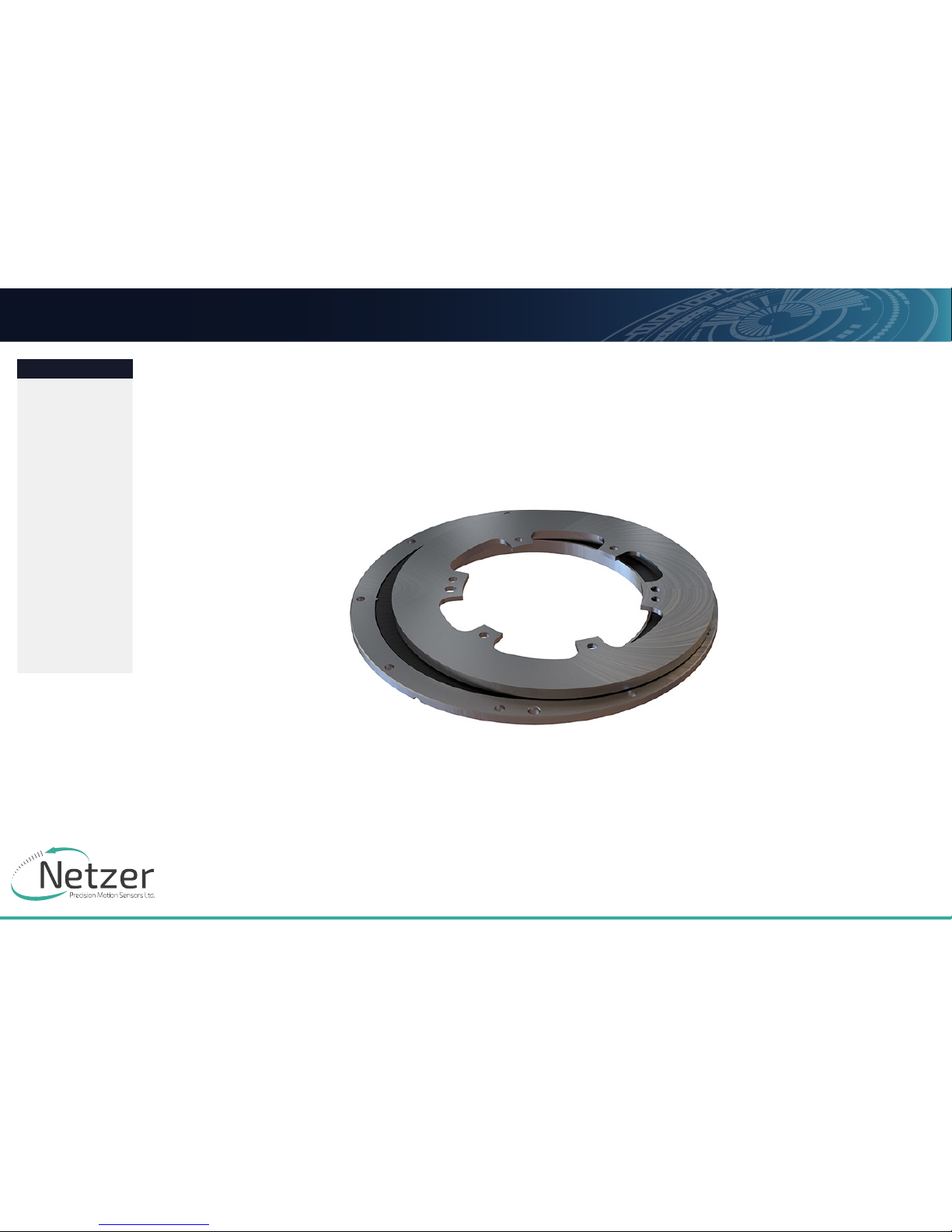
DF-150 Rotary Electric Encoder
Copyright © 2013 Netzer Precision Motion Sensors LTD, All rights reserved.
Absolute Position Encoder
Page 2
User ManUal
Page 2 of 16
DF-150 User Manual | Rev 1.0
Netzer Precision Motion Sensors LTD Propriety
Preface
Safety
Product Overview
Unpacking
Electrical
Connection
Software
Installation
Mounting
Verification
Calibration
Mechanical ICD
Mounting options
JUNE 2016
All specifications are subject to change without notice
Contents
DF-150 Rotary Electric Encoder
1.1
Table of ConTenTs
1. Preface 3
1.1 Version : 1.0 April 2016 3
1.2 Applicable documents 3
2. Safety 3
2.1 Safety issues 3
2.2 ESD notes 3
3. Product Overview 4
3.1 Overview 4
3.2 Installation flow chart 4
3.3 Encoder Mounting 5
4. Unpacking 7
4.1 Standard Order 7
5. Electrical interconnection 8
6. Software Installation 9
6.1 Minimum Requirements 9
6.2 Installing the Software 9
7. Calibration 12
7.1 Oset Calibration 12
8. Mounting Verification 13
8.1 Starting the Encoder Explorer 13
8.2 Mechanical Installation Verification 13
8.3 CAA Calibration 14
8.4 Setting the Encoder Zero Point 15
8.5 Jitter test 15
Page 3
User ManUal
Page 3 of 16
DF-150 User Manual | Rev 1.0
Netzer Precision Motion Sensors LTD Propriety
Preface
Safety
Product Overview
Unpacking
Electrical
Connection
Software
Installation
Mounting
Verification
Calibration
Mechanical ICD
Mounting options
JUNE 2016
All specifications are subject to change without notice
Contents
DF-150 Rotary Electric Encoder
1. PREFACE
1.1
Version : 1.0 april 2016
1.2
appliCable doCumenTs
■ DF-150 Electric Encoder data sheet
2. SAFETY
2.1
safeTy issues
2.2
esd noTes
Although the DF-150 Electric Encoder is insensitive to ESD
and parasitic capacitive coupling from adjacent AC voltages,
we highly recommend to enable a discharge path with <20 kΩ
between the machine shaft and the electronics ground.
Shielding: the Electric Encoder housing material is nonconductive polymer – ULTEM, the internal ground (return)
path of the 5V power supply IS NOT CONNECTED to the cable
shielding. We highly recommend grounding the cable shielding
through the connector body or by other means.
Note: During high-speed rotation, bearings may isolate the shaft
from its grounding. It is essential the shaft remain grounded
using a sustainable method during such high-speed operations.
Page 4
User ManUal
Page 4 of 16
DF-150 User Manual | Rev 1.0
Netzer Precision Motion Sensors LTD Propriety
Preface
Safety
Product Overview
Unpacking
Electrical
Connection
Software
Installation
Mounting
Verification
Calibration
Mechanical ICD
Mounting options
JUNE 2016
All specifications are subject to change without notice
Contents
DF-150 Rotary Electric Encoder
3. PRODUCT OVERVIEW
3.1
oVerView
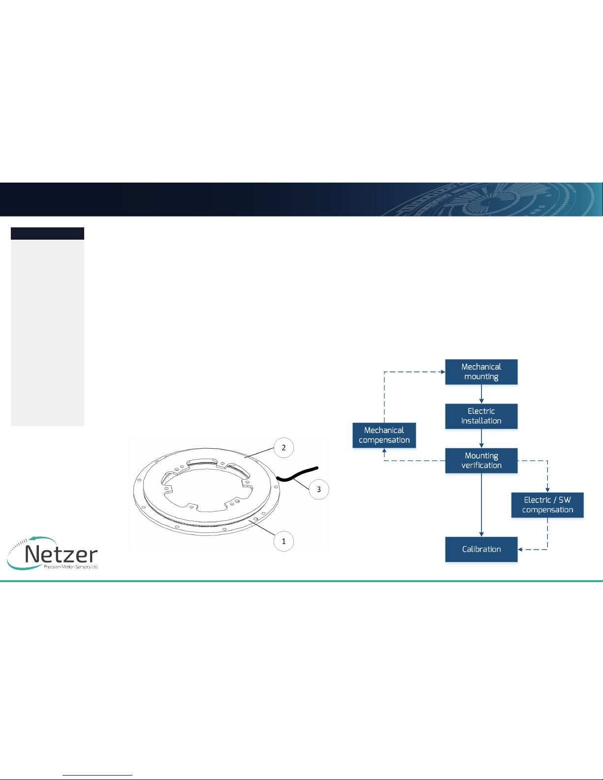
The DF-150 absolute position Electric Encoder™ is a
revolutionary position sensor originally developed for harsh
environment critical applications. Currently it performs in
a broad range of applications, including defense, homeland
security, aerospace, and medical and industrial automation.
The Electric Encoder™ non-contact technology relies on an
interaction between the measured displacement and a space/
time modulated electric field.
The DF-150 Electric Encoder™ is semi-modular, i.e., its rotor and
stator are separate, with the stator securely housing the rotor.
(1) Encoder stator
(2) Encoder rotor
(3) Encoder cable
3.2
insTallaTion flow CharT
Page 5
User ManUal
Page 5 of 16
DF-150 User Manual | Rev 1.0
Netzer Precision Motion Sensors LTD Propriety
Preface
Safety
Product Overview
Unpacking
Electrical
Connection
Software
Installation
Mounting
Verification
Calibration
Mechanical ICD
Mounting options
JUNE 2016
All specifications are subject to change without notice
Contents
DF-150 Rotary Electric Encoder
3.3
enCoder mounTing
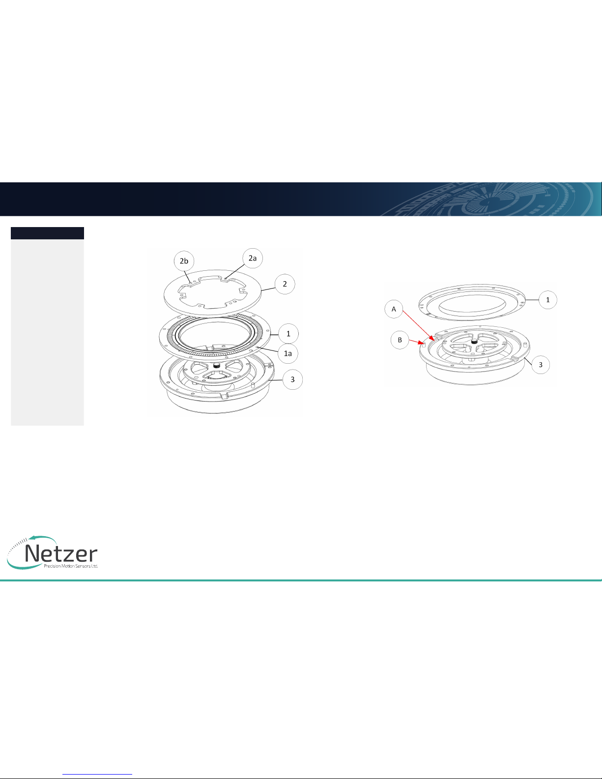
Typical encoder installation includes
■ Encoder stator (1) – Encoder stator , mounting centralization holes (1a)
■ Encoder rotor (2) –Encoder rotor ,shaft mounting hole (2a) and centralization hole (2b)
■ Encoder Seating / stator (host machine) (3) - with appropriate
The encoder stator is connected to the application static section and should be centralized
by the circumference step (A) , 2 pins (B) fixed by [6] six screws (1a), the encoder rotor
should be fixed by [4] four screws and centralized by 2 pins (2b).
Page 6
User ManUal
Page 6 of 16
DF-150 User Manual | Rev 1.0
Netzer Precision Motion Sensors LTD Propriety
Preface
Safety
Product Overview
Unpacking
Electrical
Connection
Software
Installation
Mounting
Verification
Calibration
Mechanical ICD
Mounting options
JUNE 2016
All specifications are subject to change without notice
Contents
DF-150 Rotary Electric Encoder
E
ncoder Stator / rotor relative poSition
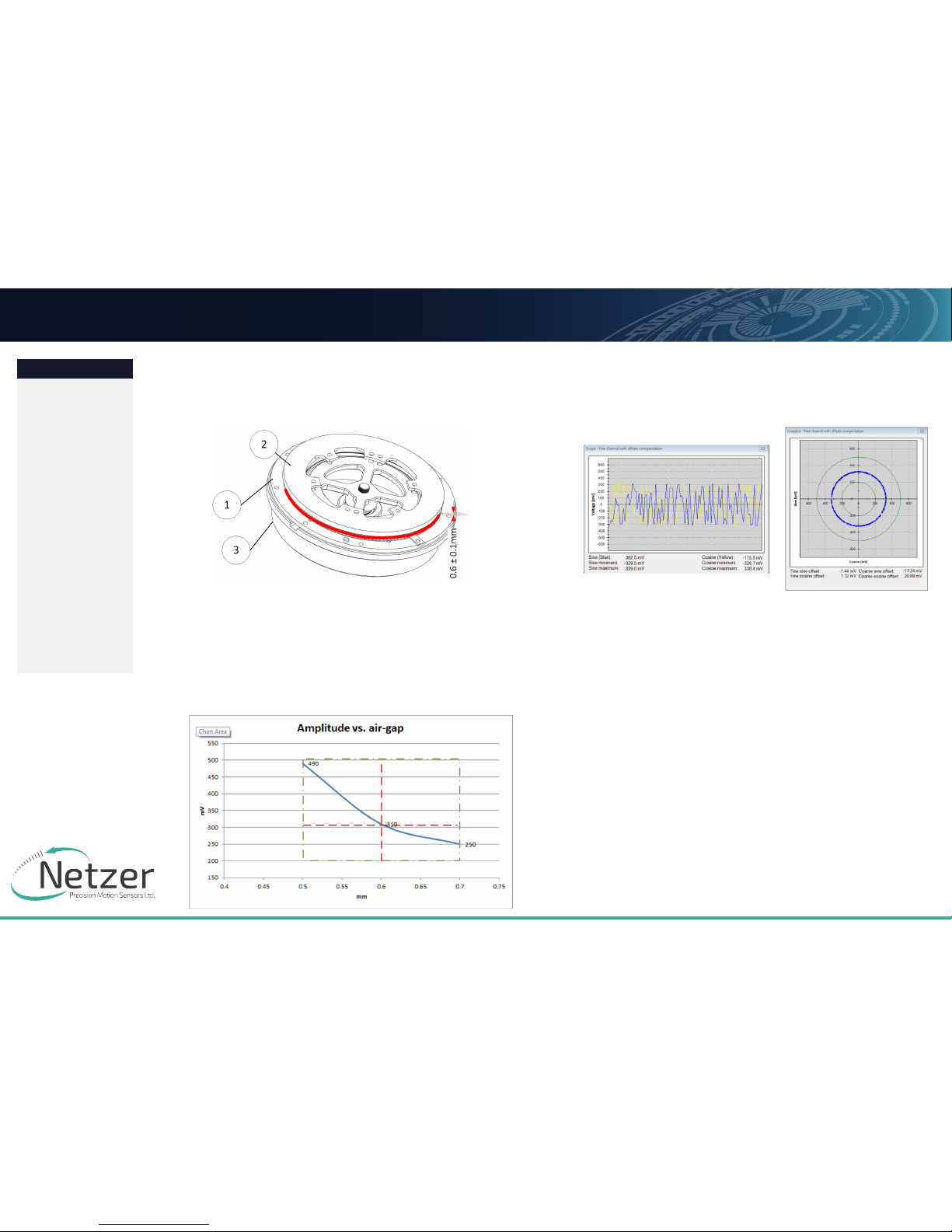
For proper performance the air gap should be
0.6mm +/- 0.1mm.
Proper mounting will ensure correct amplitude level of
Fine channel 200 - 500mV
Coarse channel 200 - 500mV
Proper rotor mounting can be verified by using the
Encoder Explorer tools “signal analyzer” or “Mechanical
installation verification”
Page 7
User ManUal
Page 7 of 16
DF-150 User Manual | Rev 1.0
Netzer Precision Motion Sensors LTD Propriety
Preface
Safety
Product Overview
Unpacking
Electrical
Connection
Software
Installation
Mounting
Verification
Calibration
Mechanical ICD
Mounting options
JUNE 2016
All specifications are subject to change without notice
Contents
DF-150 Rotary Electric Encoder
4. UNPACKING
4.1
sTandard order
The package of the standard DF-60 contains the encoder with 250mm shildedd cable AWG30.
optional acceSSorieS:
(1) MP-01014 , DF-150 ,0.6mm filler guage
(2) RJ-DF-150 , DF-150 demo jig
(3) EAPK008 , Kit , encoder mounting screws (3 screws M2x6)
(5) CNV-0003 , RS-422 to USB converter (with USB internal 5V power supply path)
Page 8
User ManUal
Page 8 of 16
DF-150 User Manual | Rev 1.0
Netzer Precision Motion Sensors LTD Propriety
Preface
Safety
Product Overview
Unpacking
Electrical
Connection
Software
Installation
Mounting
Verification
Calibration
Mechanical ICD
Mounting options
JUNE 2016
All specifications are subject to change without notice
Contents
DF-150 Rotary Electric Encoder
5. ELECTRICAL INTERCONNECTION
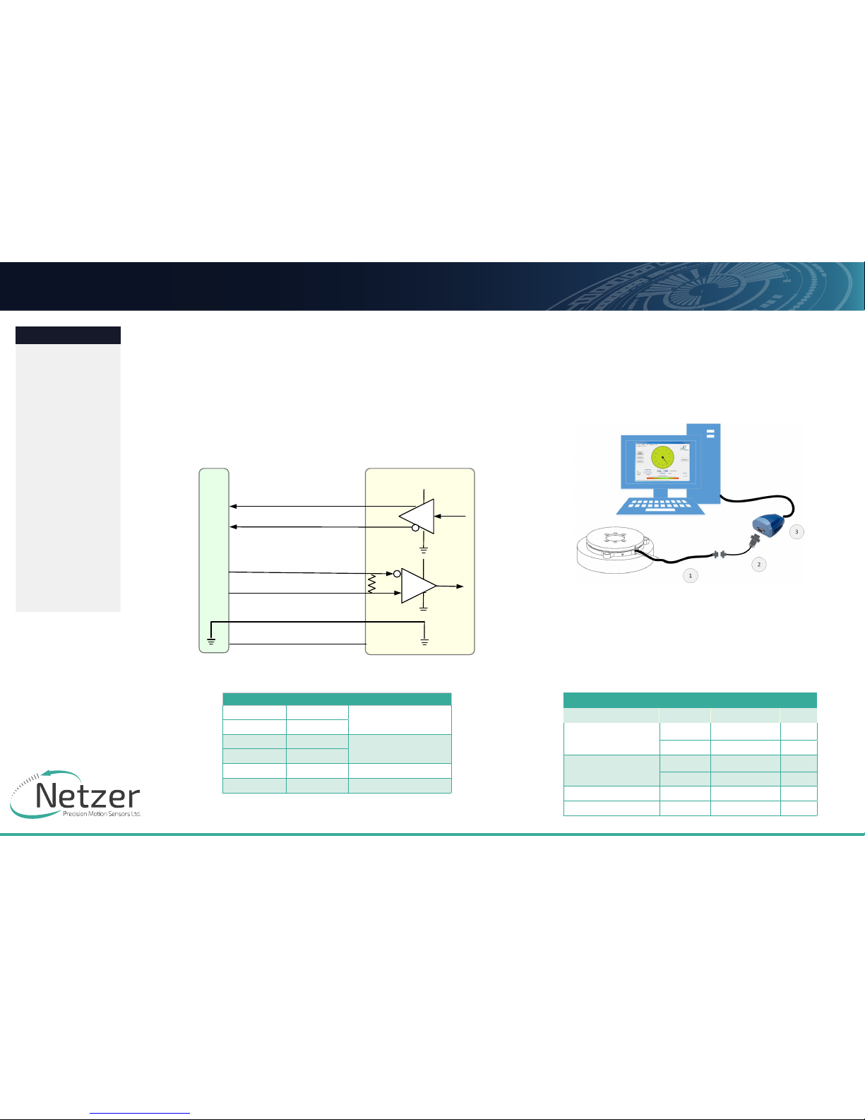
This chapter reviews the steps required to electrically connect
the DF-150 with digital interface (SSi or BiSS-C).
connecting the encoder
The DF-150 operates has two operational modes:
(i) i. Absolute Position over SSi or BiSS-C: This is the power-up
default mode.
(ii) Configuration and setup mode:
This service mode provides access via USB to a PC running
Netzer Encoder Explorer application (on MS Windows 7/8).
Communication is via Netzer Communication Protocol (NCP) over
RS-422 using the same set of wires.
Use the following pin assignment to connect the encoder to a
9-pin D-type connector to the RS-422/USB converter CNV-0003.
SSi / BiSS interface wires color code
Clock + Grey
Clock
Clock - Blue
Data - Yellow
Data
Data + Green
GND Black Ground
+5V Red Power supply
5V
HostSystem
CLK/NCPRX[+]
CLK/NCPRX[‐]
5V
5V
120Ω
(red)
(yellow)
(green)
(blue)
(gray)
(black)
ElectricEncoder™
Gnd
DATA/NCPTX[‐]
DATA/NCPTX[+]
Electric Encoder interface , D Type 9 pin Female
Description Color Function Pin No
SSi Clock / NCP RX
Gray Clock / RX + 2
Blue Clock / RX - 1
SSi Data / NCP TX
Yellow Data / TX - 4
Green Data / TX + 3
Ground Black GND 5
Power supply Red +5V 8
(1) DF-60 encoder with SSi / BiSS interface.
(2/3) RS-422 / USB converter (CAT No. CNV-00003)
Page 9
User ManUal
Page 9 of 16
DF-150 User Manual | Rev 1.0
Netzer Precision Motion Sensors LTD Propriety
Preface
Safety
Product Overview
Unpacking
Electrical
Connection
Software
Installation
Mounting
Verification
Calibration
Mechanical ICD
Mounting options
JUNE 2016
All specifications are subject to change without notice
Contents
DF-150 Rotary Electric Encoder
6. SOFTWARE INSTALLATION
The Electric Encoder Explorer (EEE) software:
■ Verifies Mechanical Mounting Correctness
■ Osets Calibration
■ Sets up general and signal analysis
This chapter reviews the steps associated with installing the EEE
software application.
6.1
minimum requiremenTs
■ Operating system: MS windows 7 , 32 / 64 bit
■ Memory: 4MB minimum
■ Communication ports: USB 2
■ Windows .NET Framework , V4 minimum
6.2
insTalling The sofTware
Run the Electric Encoder™ Explorer file found on our website:
Encoder Explorer Sw Tools.
5.3 Electrical connection and grounding
The DF-150 does NOT come with specified cable and connector, however,
do observe grounding consideration:
[1] The cable shield does not connect to the power supply return line.
[2] Ground the host shaft to avoid interference from the host system,
which could result in encoder internal noise.
Note : 4.75 to 5.25 VDC power supply required
Page 10
User ManUal
Page 10 of 16
DF-150 User Manual | Rev 1.0
Netzer Precision Motion Sensors LTD Propriety
Preface
Safety
Product Overview
Unpacking
Electrical
Connection
Software
Installation
Mounting
Verification
Calibration
Mechanical ICD
Mounting options
JUNE 2016
All specifications are subject to change without notice
Contents
DF-150 Rotary Electric Encoder
7. MOUNTING VERIFICATION
Perform mounting verification before calibration to ensure optimal
performance by selecting [Verification] on the main screen of the
Encoder Explorer or by using the signal analyzer under “Tools.”
7.1
sTarTing The enCoder explorer
Make sure to complete the following tasks successfully:
■ Mechanical Mounting
■ Electrical Connection
■ Connecting Encoder for Calibration
■ Encoder Explore Software Installation
Run the Electric Encoder Explorer tool (EEE).
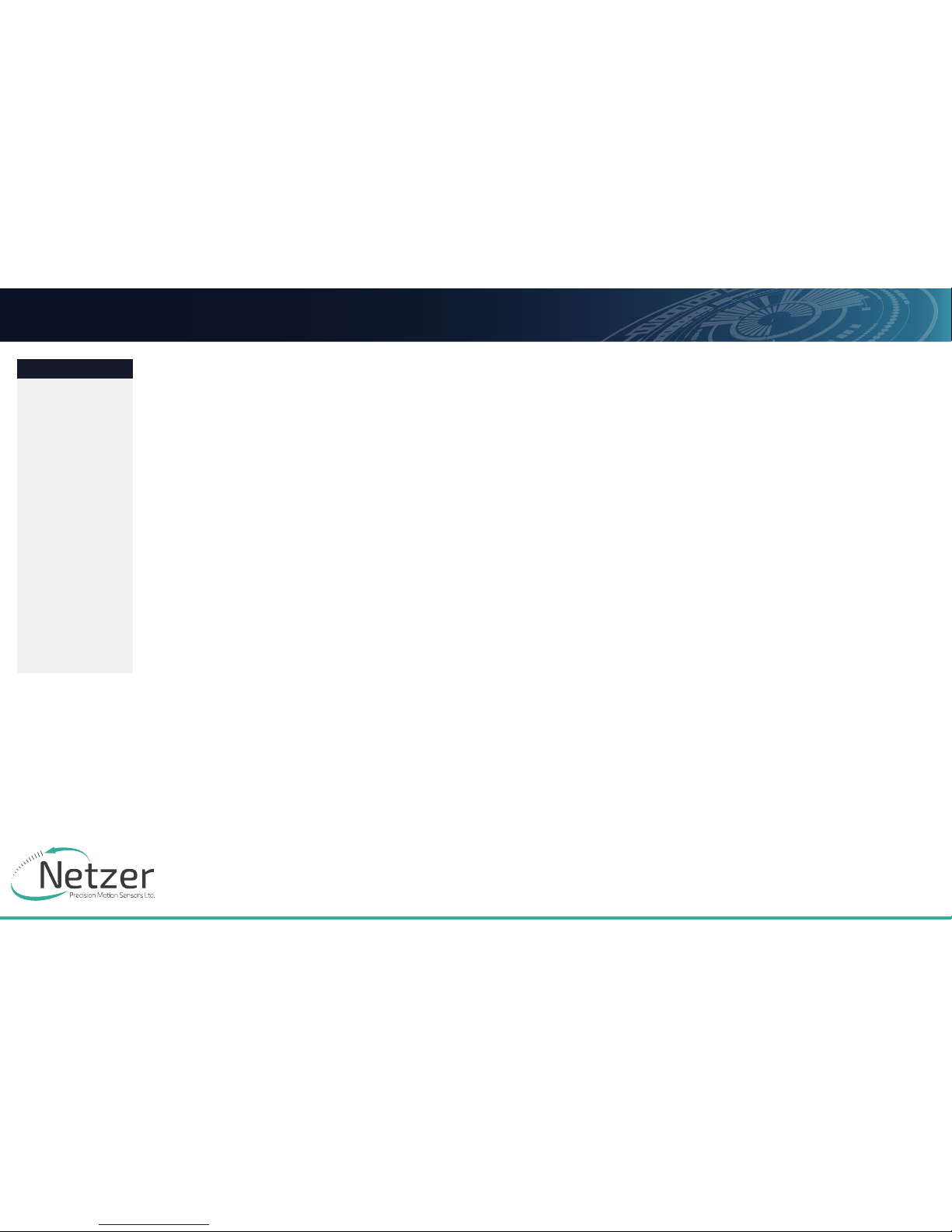
Ensure proper communication with the encoder:
(a) The status bar indicates successful communication.
(b) Encoder data displays in the Encoder data area. (CAT No., serial No.)
(c) The position dial display responds to shaft rotation.
7.2
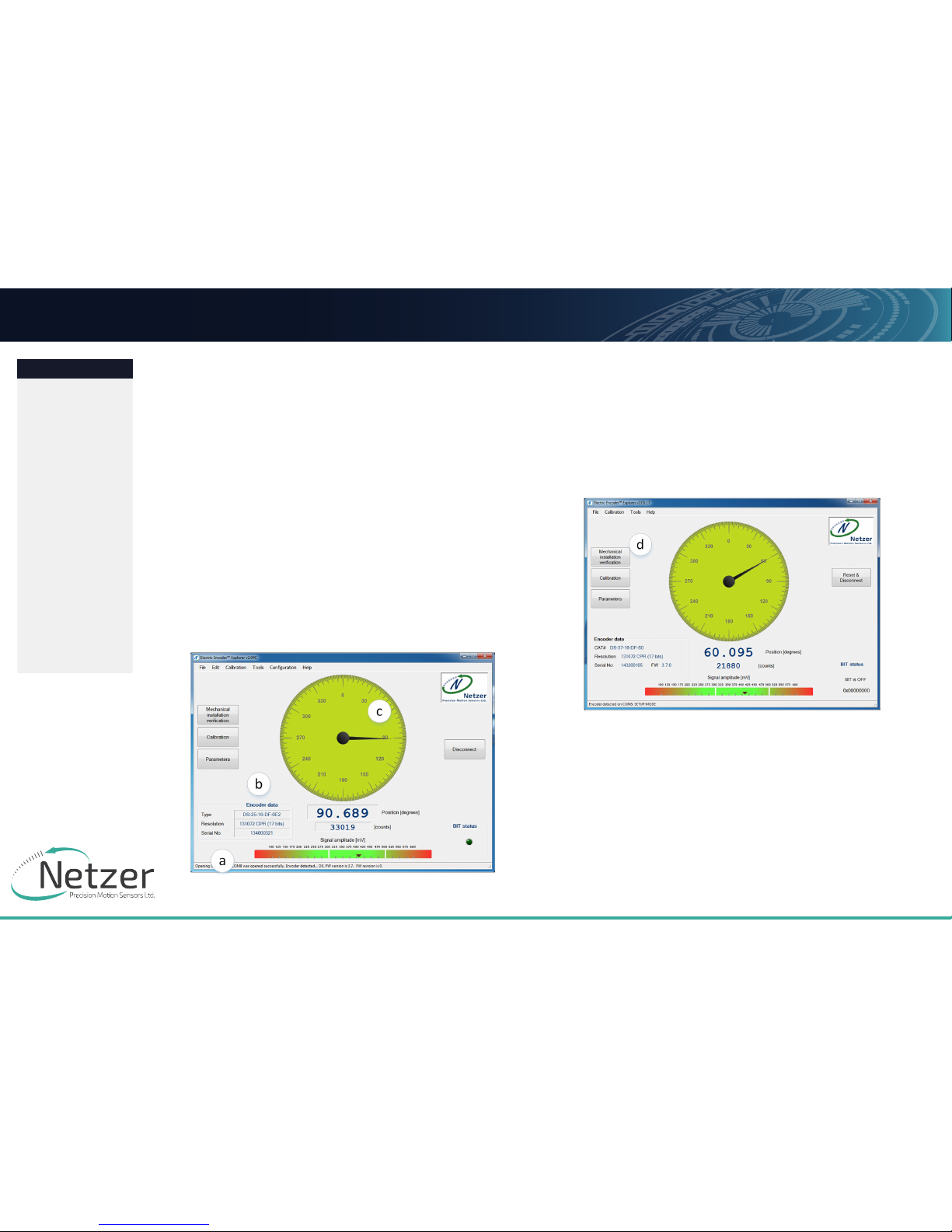
meChaniCal insTallaTion VerifiCaTion
The Mechanical Installation Verification provides procedures to
ensure proper mechanical mounting by collecting raw data of
the coarse and fine channels during rotation.
(d) Select [Mechanical Mounting Verification] on the main
screen.
Page 11
User ManUal
Page 11 of 16
DF-150 User Manual | Rev 1.0
Netzer Precision Motion Sensors LTD Propriety
Preface
Safety
Product Overview
Unpacking
Electrical
Connection
Software
Installation
Mounting
Verification
Calibration
Mechanical ICD
Mounting options
JUNE 2016
All specifications are subject to change without notice
Contents
DF-150 Rotary Electric Encoder
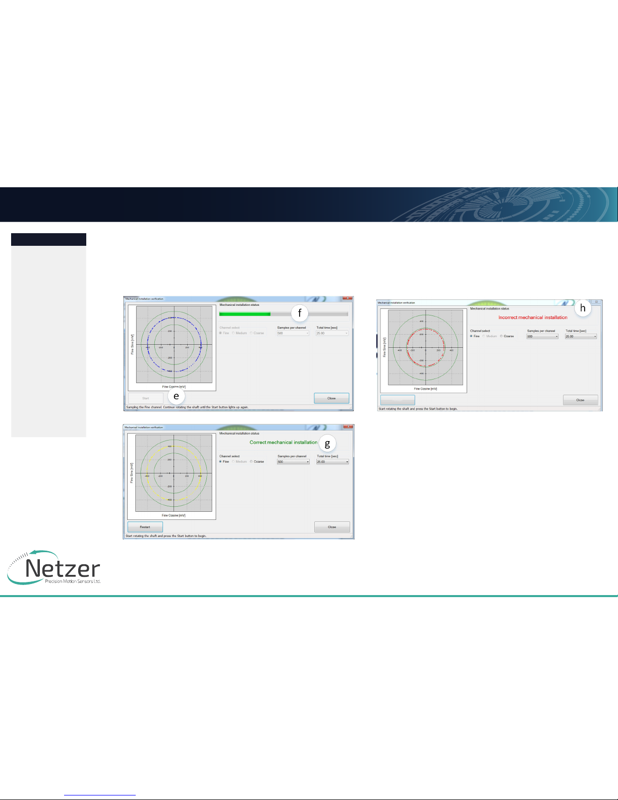
(e) Select [Start] to initiate the data collection.
(f) Rotate the shaft for data collecting of the fine/coarse
channels.
(g) At the end of successful verification, SW shows “Correct
Mechanical Installation.”
(h) If SW indicates “Incorrect Mechanical Installation,” place the
mechanical shims below the rotor, as presented in paragraph 3.3
- “Rotor Relative Position.”
Page 12
User ManUal
Page 12 of 16
DF-150 User Manual | Rev 1.0
Netzer Precision Motion Sensors LTD Propriety
Preface
Safety
Product Overview
Unpacking
Electrical
Connection
Software
Installation
Mounting
Verification
Calibration
Mechanical ICD
Mounting options
JUNE 2016
All specifications are subject to change without notice
Contents
DF-150 Rotary Electric Encoder
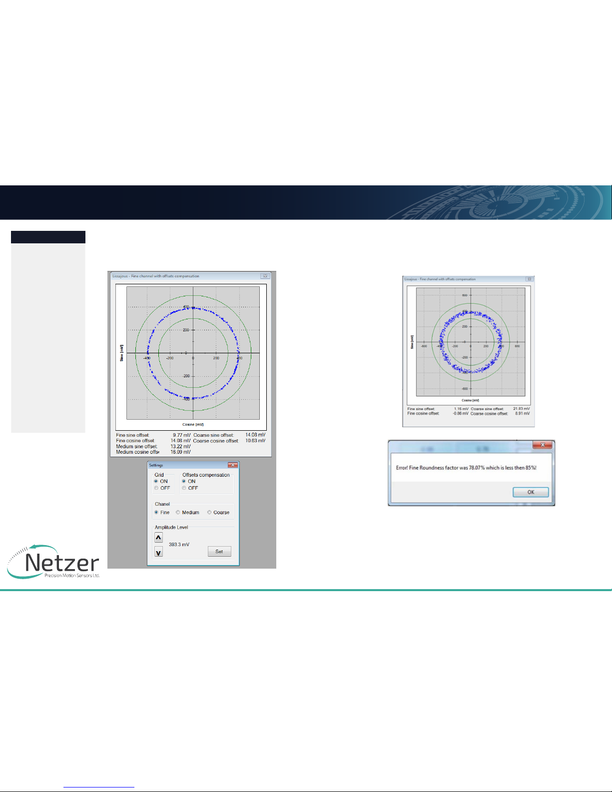
In case the reading data (blue dots) are not evenly distributed
on a thin circle, you may experience “noise” in your installation
(check shaft/stator grounding).
(i) Tools --> Signal analyzer , amplitude fine tuning option with the
UP / DOWN keys to the nominal amplitude level , save the level by
the “set” option. This process available for the fine / coarse and
medium channels.
Page 13
User ManUal
Page 13 of 16
DF-150 User Manual | Rev 1.0
Netzer Precision Motion Sensors LTD Propriety
Preface
Safety
Product Overview
Unpacking
Electrical
Connection
Software
Installation
Mounting
Verification
Calibration
Mechanical ICD
Mounting options
JUNE 2016
All specifications are subject to change without notice
Contents
DF-150 Rotary Electric Encoder
8. CALIBRATION
8.1
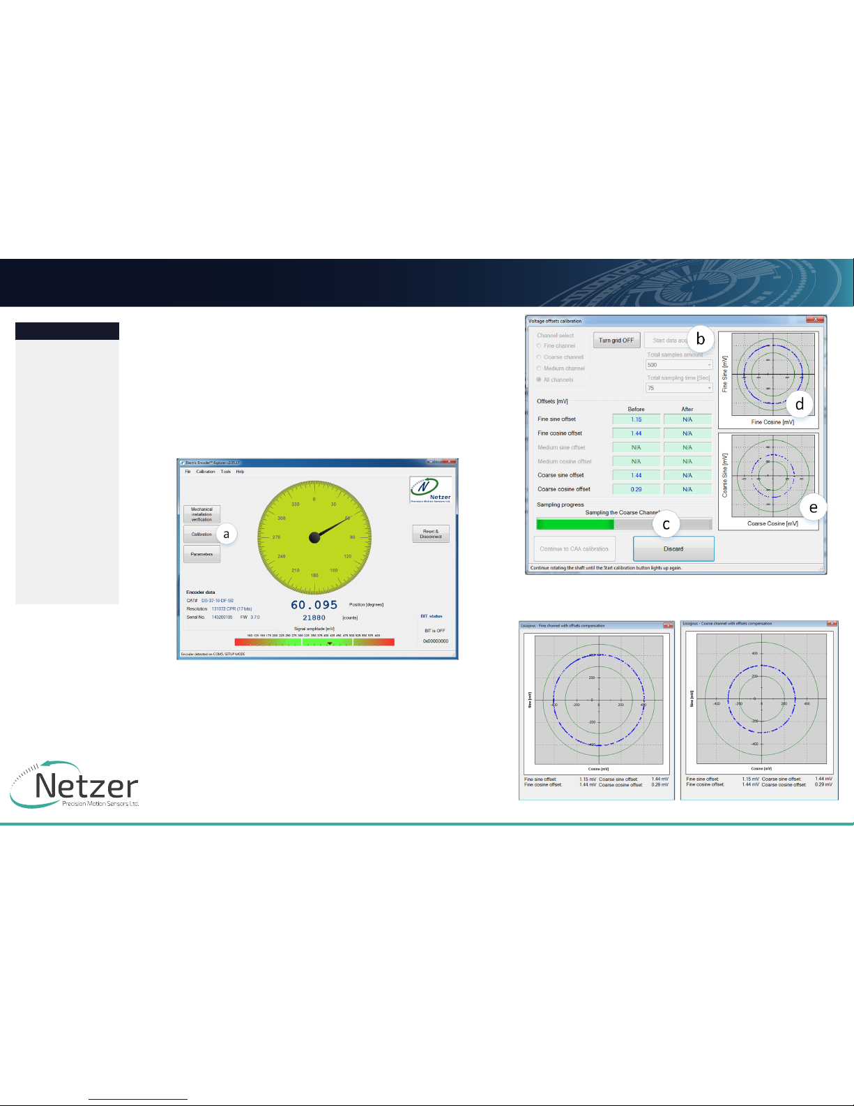
offseT CalibraTion
For optimal performance of the DF-150 Electric Encoder, the
inevitable DC oset of the sine and cosine signals must be
compensated over the operational sector.
After successfully completing the Mounting Verification
procedure:
(a) Select [Calibration] on the main screen.
(b) Start the data acquisition while rotating the shaft.
The progress bar (c) indicates the collection progress.
Rotate the axis consistently during data collection—covering
the working sector of the application end to end—by default
the procedure collects 500 points over 75 seconds. Rotation
speed is not a parameter during data collection. Data collection
indication shows for the fine/coarse channels, a clear “thin”
circle appears in the center (d) (e) with some oset.
Oset compensated Fine / Corse Channel
Page 14
User ManUal
Page 14 of 16
DF-150 User Manual | Rev 1.0
Netzer Precision Motion Sensors LTD Propriety
Preface
Safety
Product Overview
Unpacking
Electrical
Connection
Software
Installation
Mounting
Verification
Calibration
Mechanical ICD
Mounting options
JUNE 2016
All specifications are subject to change without notice
Contents
DF-150 Rotary Electric Encoder
8.2
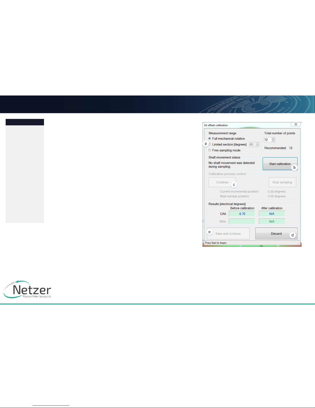
Caa CalibraTion
The following calibration aligns the coarse/fine channel by
collecting data from each point of both channels.
Select [Continue to CAA Calibration]
In the CAA angle calibration window, select the relevant option
button from the measurement range options (a):
• Full mechanical rotation – shaft movement is over 10deg -
recommended.
• Limited section – define operation of the shaft in a limited
angle defined by degrees in case of <10deg
• Free sampling modes - define the number of calibration
points in the total number of points in the text box. The system
displays the recommended number of points by default. Collect a
minimum of nine points over the working sector.
• Click the [Start Calibration] button (b)
• The status (c) indicates the next required operation; the
shaft movement status; the current position, and the next target
position to which the encoder should be rotated.
• Rotate the shaft/encoder to the next position and click the
[Continue] button (c) - the shaft should be in STAND STILL during
the data collection. Follow the indication/interactions during the
cyclic process for positioning the shaft --> stand still --> reading
calculation.
• Repeat the above step for all defined points. Finish (d)
• Click the [Save and Continue] button (e).
The last step saves the osets CAA parameters, completing the
calibration process.
Page 15
User ManUal
Page 15 of 16
DF-150 User Manual | Rev 1.0
Netzer Precision Motion Sensors LTD Propriety
Preface
Safety
Product Overview
Unpacking
Electrical
Connection
Software
Installation
Mounting
Verification
Calibration
Mechanical ICD
Mounting options
JUNE 2016
All specifications are subject to change without notice
Contents
DF-150 Rotary Electric Encoder
8.3
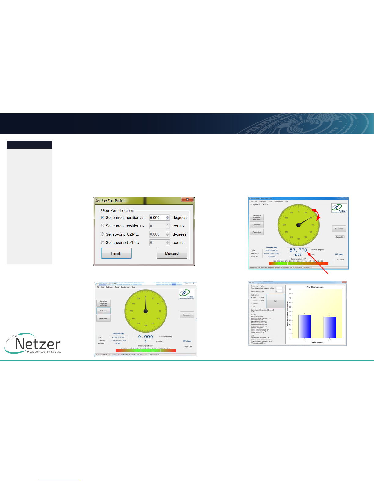
seTTing The enCoder Zero poinT
The zero position can be defined anywhere in the working sector.
■ Rotate the shaft to the desired zero mechanical position.
■ Select “Set Current Position” as zero by using the relevant
option, and click [Finish].
8.4
JiTTer TesT
Perform a jitter test to evaluate the quality of the installation;
the jitter test presents the reading statistics of absolute position
readings (counts) over time. Common jitter should be up +/three counts; higher jitter may indicate system noise.
Page 16
User ManUal
Page 16 of 16
DF-150 User Manual | Rev 1.0
Netzer Precision Motion Sensors LTD Propriety
Preface
Safety
Product Overview
Unpacking
Electrical
Connection
Software
Installation
Mounting
Verification
Calibration
Mechanical ICD
Mounting options
JUNE 2016
All specifications are subject to change without notice
Contents
DF-150 Rotary Electric Encoder
40° typ.9
166.37mm
6.55in
P.C.D.
4.80mm ±0.01
0.189in ±0.0004
4.29mm
0.17in
typ.9
4.80mm ±0.01
0.19in ±0.0004
5.59mm
0.22in
175.26mm
6.90in
60° typ.6
97.79mm
3.85in
P.C.D.
10°
4.29mm
0.17in
typ.6
85.73mm
3.38in
4.80mm ±0.01
0.19in ±0.0004
4.80mm ±0.01
0.19in ±0.0004
5.59mm
0.22in
AA
110.49mm
4.35in
152.78mm
6.01in
149.94mm
5.90in
3.33mm
0.13in
0.64mm
0.03in
7.92mm
0.31in
13.64mm
0.54in
SECTION A-A
2
1
ITEM NO.
DESCRIPTION
QTY.
1
DF-150
ֹ
_stator_assy
1
2
DF-150_rotor_assy
1
D
E
F
C
1
2
3
4
B
A
3
2
1
5
C
D
4
6
7
8
A
B
The information contaned in this drawing is the sole property ot Netzer Precision Motion Sensores Ltd. Any reproduction in part or
whole without the written permission of Netzer Precision Motion Sensors Ltd.is prohibited. The drawing is confidential,and is the
property of Netzer Precision Ltd. it must not be disclosed to a third party without written consent of Netzer Precision Ltd
.
SIGNATURE
16-12-15
16-12-15
Jacob H.
Jacob H.
16-12-15
Michael A.
DF-150_ICD
A3
SHEET 1 OF 1
SCALE: 1:1
DWG NO. :
TITLE:
MATERIAL:
DATE
NAME
UNLESS OTHERWISE SPECIFIED
:
DIMENSIONS ARE IN mm
SURFACE FINISH: N6
LINEAR TOLERANCES:
0.1 mm
ANGULAR TOLERANCES:
0.5 deg
ALL CHAMFER: 0.1 mm X 45°
APPV'D
CHK'D
DRAWN
Notes:
For any incompatibility with the model or missing dimension, please refer
1.
to Netzer for clarification.
Burrs are not allowed
2.
Packing must prevent physical damage during process storage and
3.
shipment
Coating:
CAT NO. :
01
Revision :
DF-150_ICD
 Loading...