

Page 1

Series 1000 Micro8 Hub
User’s Guide
®
Unleashing the Power of NetWare
Page 2

Series 1000 Micro8 Hub User’s Guide
Product Information
You can obtain NetWorth product information or technical support in the following
ways:
t Call NetWorth technical support at 214-929-NWTH(6984) between the hours of
8:00 a.m. and 6:00 p.m. (Central Time).
t Call NetWorths BBS at 214-929-4882. The BBS is available 24 hours a day. The
modem supports up to 14.4 Kbps and is configured for no parity, 8 data bits, 1
stop bit, and no flow control.
t Access NetWorth via CompuServe under Novells Vendor Forum B (Go
NVENB).
t Contact NetWorth via E-mail at:
Disclaimer
NetWorth, Inc. makes no representations or warranties with respect to the contents or
use of this manual, and specifically disclaims any express or implied warranties of
merchantability or fitness for any particular purpose. Further, NetWorth, Inc. reserves
the right to revise this publication and to make changes to its content, at any time,
without obligation to notify any person or entity of such revision or changes.
Trademarks
NetWorth, Inc. has made every effort to supply trademark information about company
names, products, and services mentioned in this book.
NetWorth® is a registered trademark of NetWorth, Inc.
Micro8 is a trademark of NetWorth, Inc.
Copyright © 1995 NetWorth, Inc. All rights reserved.
No part of this publication may be reproduced, photocopied, stored on a retrieval
system, or transmitted without express prior written consent of the publisher.
Printed in the U.S.A.
ii
Page 3

Series 1000 Micro8 Hub User’s Guide
FCC Radio Frequency Interference
Regulatory Statement
Computing devices and peripherals manufactured by NetWorth generate, and can
radiate, radio frequency energy, and if not installed and used in accordance with the
instructions in this manual, may cause interference to radio communications. Such
equipment has been tested and found to comply with the limits for a Class A computing
device pursuant to Part 15 of the FCC Rules, which are designed to provide reasonable
protection against radio interference when operated in a commercial environment.
Operation of this equipment in a residential area is likely to cause interference, in which
case the user at his own expense will be required to take whatever measures
necessary to correct the interference.
Some components may not have been manufactured by NetWorth, Inc. If not,
NetWorth has been advised by the manufacturer of the component that it has been
tested and complies with the Class A computing device limits as described above.
Canadian Department of Communications
Radio Frequency Statement
This digital apparatus does not exceed the Class A limits for radio noise emissions from
digital apparatus set out in the Radio Interference Regulations of the Canadian
Department of Communications.
Le présent appareil numérique német pas de bruits radioélectriques dépassant les
limites applicables aux apparils numériques de la classe A prescrites dans le Règlement
sur le broullage radioélectrique édicté par le ministerès des Communications du
Canada.
Conformance to CISPR 22, Class A (EN55022)
This equipment complies with the EMI requirements of EN55022 for Class A
computing devices.
iii
Page 4

Series 1000 Micro8 Hub User’s Guide
End Customer Product Warranty
This is the warranty between NetWorth, Inc. (hereinafter called “us”) and the original end
user of NetWorth product (hereinafter called “you”).
Warranty Term
We warrant all product manufactured by us to be free from defects in material and
workmanship under normal use and service for a period of one year from their date of
purchase. This warranty is offered only to you, the original end customer, and is subject
to the exceptions below.
We offer you a lifetime warranty on all components in the Series 1000, Series 2000 and
Series 3000 products. Fans and power supplies are excepted from this policy and carry
a three (3) year warranty from the date of purchase.
We offer you an unconditional Lifetime Warranty on all NetWorth Adapters.
Except as set forth below, if the product fails to be in good working order at any
time during the applicable warranty period, we will, at our sole option, repair or
replace the product at no additional charge.
Limitations
Under no conditions does our warranty include service to repair damage to the product
resulting from accidents, disaster, misuse, abuse, misapplication or from modification of
the product performed by any party other than NetWorth.
Service Covered by Warranty
If your product fails within thirty days after you receive it, it should be returned directly to
us. Please contact our Customer Service Department directly at (214) 929-1700 and
follow the procedures listed below in the section titled “NetWorth Return Procedures.”
If you need service during the rest of the warranty period, you must return the unit to the
reseller from whom you purchased it. If you r rese ller is no long er in busine ss, you ma y
contact our Customer Service Department directly at (214) 929-1700. In this case, please
be prepared to give us the serial number of the equipment and the approximate original
purchase date.
Out-of-Warranty Service
If the product needs repair after the warranty is over, we will do so for a flat rate fee. Y ou
can get specific repair pricing and shipping costs by calling our Customer Service
Department at (214) 929-1700. You must follow the return procedures outlined below.
NetWorth Return Procedures
If service is required directly from NetWorth, either because the reseller is out of business
or because the warranty has expired, please follow this procedure:
a) Contact our Customer Service department at (214) 929-1700 and request a Return
Material Authorization (RMA) number. Please be prepared to provide the serial number
of the failing product, the name of the reseller from whom you purchased the product and
a description of the failure that is as complete as possible.
iv
Page 5

Series 1000 Micro8 Hub User’s Guide
b) We will use the serial number you give us to find the original shipment date of the item.
The Customer Service Department can advise you of this date. If the product was not
purchased directly from NetWorth (for instance, through a reseller) and is within warranty
from the purchase date, but not from the original shipment date, we will ask you to include
a copy of the original seller’s invoice for the product showing the date of purchase if you
request in-warranty service.
c) Please pack the product in its’ original container and packing or a reasonable
equivalent. If you need instruction on packing the unit, Customer Service can help you
with this at the time that the RMA number is issued.
d) Note the RMA number CLEARLY on the outside of the shipping box.
Customer Remedies
Our entire liability and your exclusive remedy sha ll be, at our sole option, the repair o r
replacement of defective products. Repair parts and products may be either
reconditioned or new, but, if reconditioned, shall be of the same quality and carry the
same warranty as new parts or products. All replaced parts become the property of
NetWorth.
Product Changes
NETWORTH RESERVES THE RIGHT TO MAKE CHANGES IN ITS PRODUCTS
WITHOUT OBLIGATION TO INCORPORATE SUCH CHANGES INTO ANY PRODUCT
PREVIOUSLY MANUFACTURED.
Limitations
THE FOREGOING LIMITED WARRANTY AND REMEDIES ARE EXCLUSIVE AND
EXPRESSLY IN LIEU OF ALL OTHER WARRANTIES EXPRESS OR IMPLIED, EITHER
IN FACT OR BY OPERATION OF LAW, STATUTORY OR OTHERWISE, INCLUDING
WARRANTIES OF A NEW DESIGN, MERCHANTABILITY OR FITNESS OF USE.
NETWORTH NEITHER ASSUMES NOR AUTHORIZES ANY OTHER PERSON TO
ASSUME FOR IT OTHER LIABILITY IN CONNECTION WITH THE SALE,
INSTALLATION OR USE OF ITS PRODUCTS. SOME STATES DO NOT ALLOW
LIMITATION ON HOW LONG AN IMPLIED WARRANTY LASTS, SO THE ABOVE
LIMITATIONS MAY NOT APPLY TO YOU.
AS WARRANTED ABOVE, YOUR SOLE REMEDY SHALL BE THE REPAIR OR
REPLACEMENT OF THE PRODUCT. IN NO EVENT WILL NETWORTH BE LIABLE
FOR ANY DAMAGES, INCLUDING LOST PROFITS, LOST SAVINGS OR INCIDENT AL
OR CONSEQUENTIAL DAMAGES ARISING OUT OF THE USE OF OR INABILITY TO
USE SUCH PRODUCT — EVEN IF NETWORTH OR A CERTIFIED RESELLER OR
DISTRIBUTOR HAS BEEN ADVISED OF THE POSSIBILITY OF SUCH DAMAGES —
OR FOR ANY CLAIM BY ANY OT HER PARTY.
SOME STATES DO NOT ALLOW THE EXCLUSION OR LIMITATION OF INCIDENTAL
OR CONSEQUENTIAL DAMAGES FOR CONSUMER PRODUCTS, SO THE ABOVE
LIMITATIONS OR EXCLUSIONS MAY NOT APPL Y TO YOU. THIS W ARRANTY GIVES
YOU SPECIFIC LEGAL RIGHTS AND YOU MAY HAVE OTHER RIGHTS WHICH VARY
FROM STATE TO STATE.
v
Page 6

Contents
Preface
Chapter 1—Overview
Features of the Micro8...........................................................................1-1
Technical Specifications.........................................................................1-2
LED Indicators .......................................................................................1-5
Chapter 2—Setting Up th e Mi cro 8
About This Chapter................................................................................2-1
Selecting a Location ..............................................................................2-2
Environmental Requirements.........................................................2-2
Electrical Requirements .................................................................2-2
Spatial Requirements.................................... ..... ..... ..... ..... ..... ... .....2-2
Connecting Power .................................................................................2-3
Domestic Connections ...................................................................2-3
International Connections...............................................................2-5
Cabling Considerations..........................................................................2-6
Twisted-Pair Wire Specifications....................................................2-6
Hub-to-Workstation Connection.....................................................2-9
Setting the Uplink Switch.....................................................................2-10
Sample Network Configurations..........................................................2-11
Single Hub Configuration .............................................................2-11
Multiple Hub Configuration...........................................................2-12
Maximum Repeater Path Model...................................................2-13
AUI Connections...........................................................................2-14
BNC Model ...................................................................................2-15
Thin Ethernet Connections...........................................................2-16
Glossary
Index
vii
Page 7

Preface
his guide describes how to install and configure NetWorths Series 1000 Micro8
Hub. Be sure you read all chapters in this guide to ensure that you successfully
T
install and use the hub.
Before you start, verify that this package contains the following items:
t Series 1000 Micro8 Hub, domestic or international version:
l Domestic version for the following options:
Basic (Part No. MICRO8)
AUI (Part No. MICRO8-A)
BNC (Part No. MICRO8-B )
UTP (Part No. MICRO8-U)
l International version for the following options:
Basic (Part No. MICRO8-I)
AUI (Part No. MICRO8-IA)
BNC (Part No. MICRO8-IB)
UTP (Part No. MICRO8-IU
t Series 1000 Micro8 Hub Users Guide
t Power supply module
t Warranty card
ix
Page 8

Overview 1
he Series 1000 Micro8 Hub is the ideal connectivity solution for departmental
Ethernet networks that contain 8 to 32 nodes. The Micro8 is easy to configure and
T
maintain, plus it is capable of built-in port management.
More importantly, the four Micro8 versions (Basic, AUI, BNC, and UTP) let you
expand your network to other configurations without sacrificing your existing network
configuration. For example, if you currently have a 10BASE-T RJ-45 backbone
network, you can easily add eight, inexpensive UTP ports by choosing the basic,
Micro8 version. In the same way, you can connect a 10BASE-5 (AUI) or a 10BASE-2
(BNC) backbone network to other configurations of your choice by selecting the
appropriate Micro8 version. You can even add a ninth 10BASE-T port with the Micro8
UTP version.
Features of the Micro8
The Micro8 supports the following features:
t Eight RJ-45 ports for connecting UTP or STP cabling to workstations and servers
in a 10BASE-T network (Basic configuration)
t Front panel uplink switch that converts RJ-45 Port 8 to an uplinkable port so the
Micro8 can connect to another hub in a star topology
t Optional AUI connector for connecting to 10BASE-5 networks
t Optional BNC connector for connection to 10BASE-2 networks
t Optional UTP connector that adds a ninth 10BASE-T port
t LEDs that indicate power, port activity, collision, and link status
t Link integrity feature that automatically partitions noisy segments and detects
broken cable segments
t Full compatibility with the IEEE 802.3 10BASE-T hub specifications for
connection to shielded/unshielded twisted-pair wiring
t Lifetime warranty
1 - 1
Page 9

Overview Technical Specifications
Technical Specifications
Dimensions
t 1.4 x 7.0 x 5.0 inches (HxWxD)
Connectors
t Eight RJ-45 connectors for UTP/STP wiring (Basic configuration; on front panel)
t AUI connector (AUI configuration; on back panel)
t BNC connector (BNC configuration; on front panel)
t UTP connector (UTP configuration; on front panel)
t Power cord connectors (all configurations; on back panels)
LED Indicators
t Power (PWR) status
t Activity (ACT) status
t Collision (COL) status
t RJ-45 port activity (LEDs 1-8 are for the AUI, BNC, and Basic Micro8 options;
LED 9X is for the UTP port Micro8 option.)
Operating Environment
t 32° to 120° F
0° to 49° C
t 5% to 95% humidity (non-condensing)
Storage Environment
t 32° to 151° F; 0° to 66° C
t 5% to 95% humidity (non-condensing)
t 0 to 30,000 feet altitude
0 to 9 kilometers
Cooling
t Convection
1 - 2
Page 10

Technical Specifications Overview
Power Requirements, Domestic
t AUI, Basic, BNC, and UTP
t 100 to 130 VAC
t 0.21 amp maximum load
t 60Hz
Power Requirements, International
t AUI, Basic, BNC, and UTP
t 210 to 250 VAC
t 0.1 amp maximum load
t 50 Hz
Power Consumption
t Typical: 7W Maximum: 11W
1 - 3
Page 11
Overview Technical Specifications
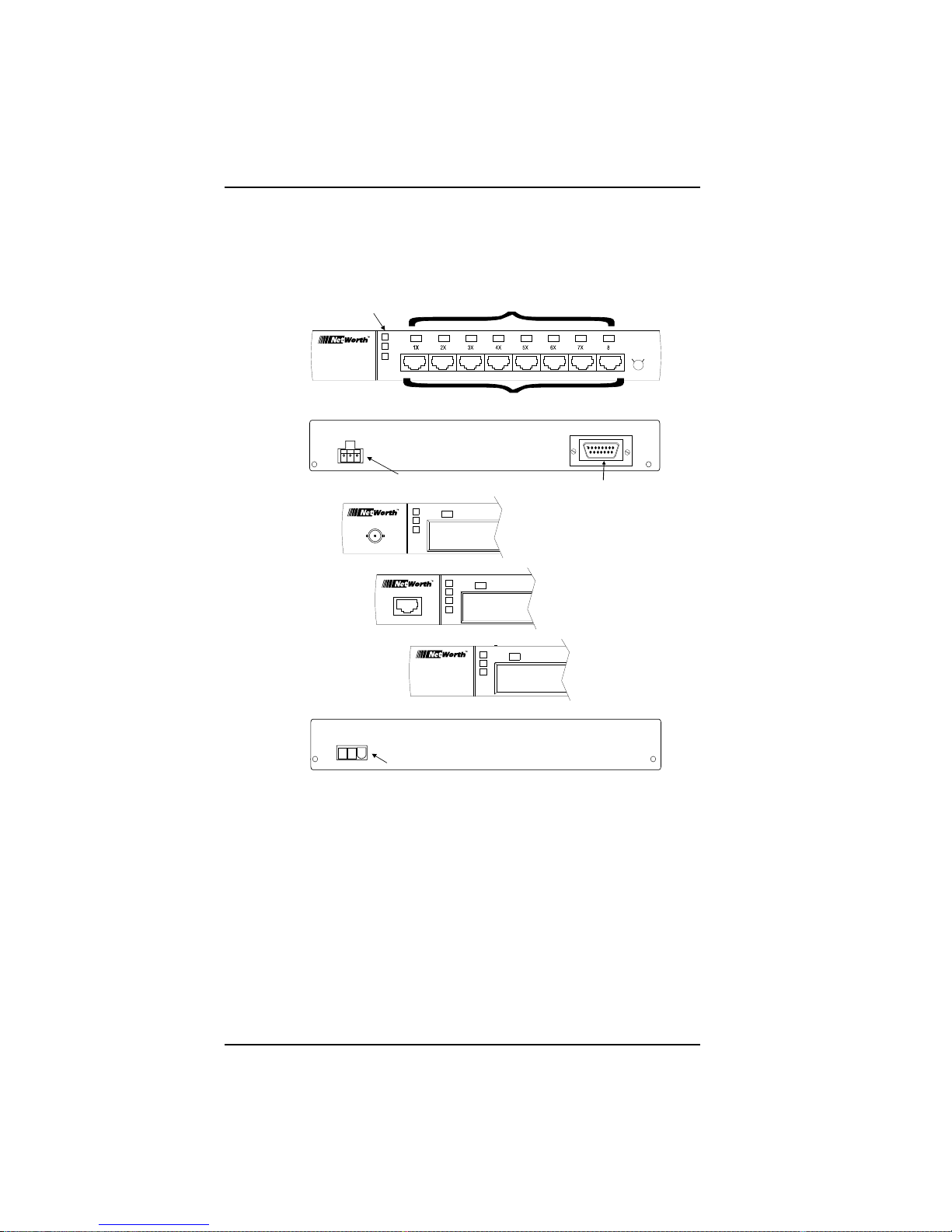
Figure 1-1 shows the Micro8 with the AUI connector mounted on the back panel; the
BNC and UTP connectors mounted on the front panel; and the Basic configuration
that contains only the eight RJ-45 ports on the front panel:
8-Port
with AUI
Option
Backpanel
with AUI
Connector
BNC, UTP,
and Basic
8-Port
Backpanel
8-Port
with BNC
(Thinnet)
Option
with UTP
(10BASE-T)
8-Port
Option
Power, Activity,
Collision LEDs
PWR
ACT
COL
Power Cord Connector
Basic
8-Port
Power Cord Connector
LEDs
MDI-X
MDI
UPLINK
RJ-45 Ports
AUI Connector
PWR
ACT
COL
9X
1 - 4
Figure 1-1: Configuration Options
Page 12

LED Indicators Overview
LED Indicators
The Micro8 contains the following LEDs that monitor hub status:
t PWR, ACT, COL, and 9XLEDs that show the hubs power status (ON or
OFF), the incoming traffic on the hub (heavy, light, or no activity), and the
collision status (heavy or light activity); the 9X LED is for the optional UTP port.
t Link Status LEDsEach RJ-45 port has a Link Status LED associated with it.
These operate in the following manner:
l When you power up the Micro8, the Link Status LEDs light momentarily,
then turn off.
l When the Micro8 connects with either a powered network station or another
Micro8, the Link Status LED associated with that port lights and remains
lighted until the connection breaks.
l If the Micro8 makes no connection, the Link Status LED does not light.
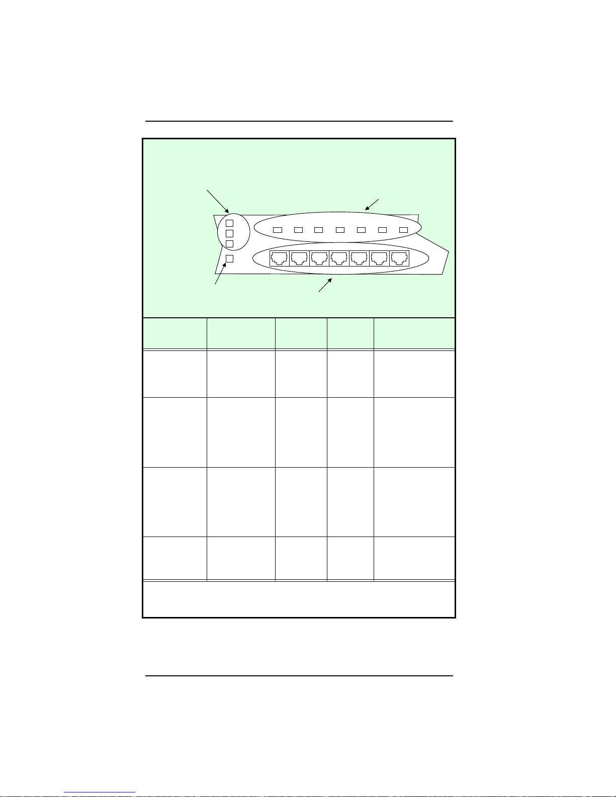
The following illustration shows the locations of the LEDs and the RJ-45 ports on the
front panel of the Micro8. The table describes the meaning of each LED color:
1 - 5
Page 13
Overview LED Indicators
LED Indicators
Power, Activity,
Collision LEDs
Link Status LEDs
PWR
ACT
COL
9X
Link Status LED
(UTP only)
LED/Color Flashing
Yellow *
PWR
ACT
COL
Link Status
Not used Power ON
Not used Heavy
Light
collisions—
Slow flashing
Heavy
collisions—Fast
flashing
Not used Link OK
(RJ-45
Port)
123
567
4
RJ-45 Ports
Green Flashing
Green
LED
Off
Not used Power OFF to
to the hub;
the hub
normal
operations
incoming
traffic
(activity)
on the port
Light
incoming
traffic
(activity)
on one of
No activity (no
incoming traffic)
on the port
the ports
Not used Not used No collisions
Not used Link failed or no
for the
RJ-45 port
connection for the
RJ-45 port
*
Flashing Yellow LEDs may appear orange on the hub’s front panel.
1 - 6
Page 14

Setting Up the Micro8 2
his chapter describes the basic requirements for setting up the Micro8, including
environmental, electrical, and spatial requirements, as well as UTP cabling
T
specifications. The chapter also explains how to power up the hub, how to make
a basic hub-to-workstation connection, and how to set up basic network configurations.
About This Chapter
This chapter contains information about the following topics:
t Selecting a Location
t Connecting Power
t Cabling Considerations
t Setting the Uplink Switch
t Sample Network Configurations
2-1
Page 15
Setting Up the Micro8 Selecting a Location
Selecting a Location
You can place the Micro8 on a level surface (a desktop or cabinet, for example) or
mount it on a vertical surface using velcro attachments. Before you select a location
for the hub, read this section to determine the necessary environmental, electrical, and
spatial requirements.
Environmental Requirements
Be sure the operating environment for the hub is within the following ranges:
t Temperature: 32 to 120F (0 to 49C)
t Humidity: 5% to 95% (non-condensing)
t Altitude: 0 to 10,000 feet
Electrical Requirements
Be sure there is a commercial power outlet within 6 feet (1.8 meters) cord distance of
the hub. If there is no outlet within this distance, use a power strip or grounded
extension cord to extend the range of the power cable. The power outlet must be a
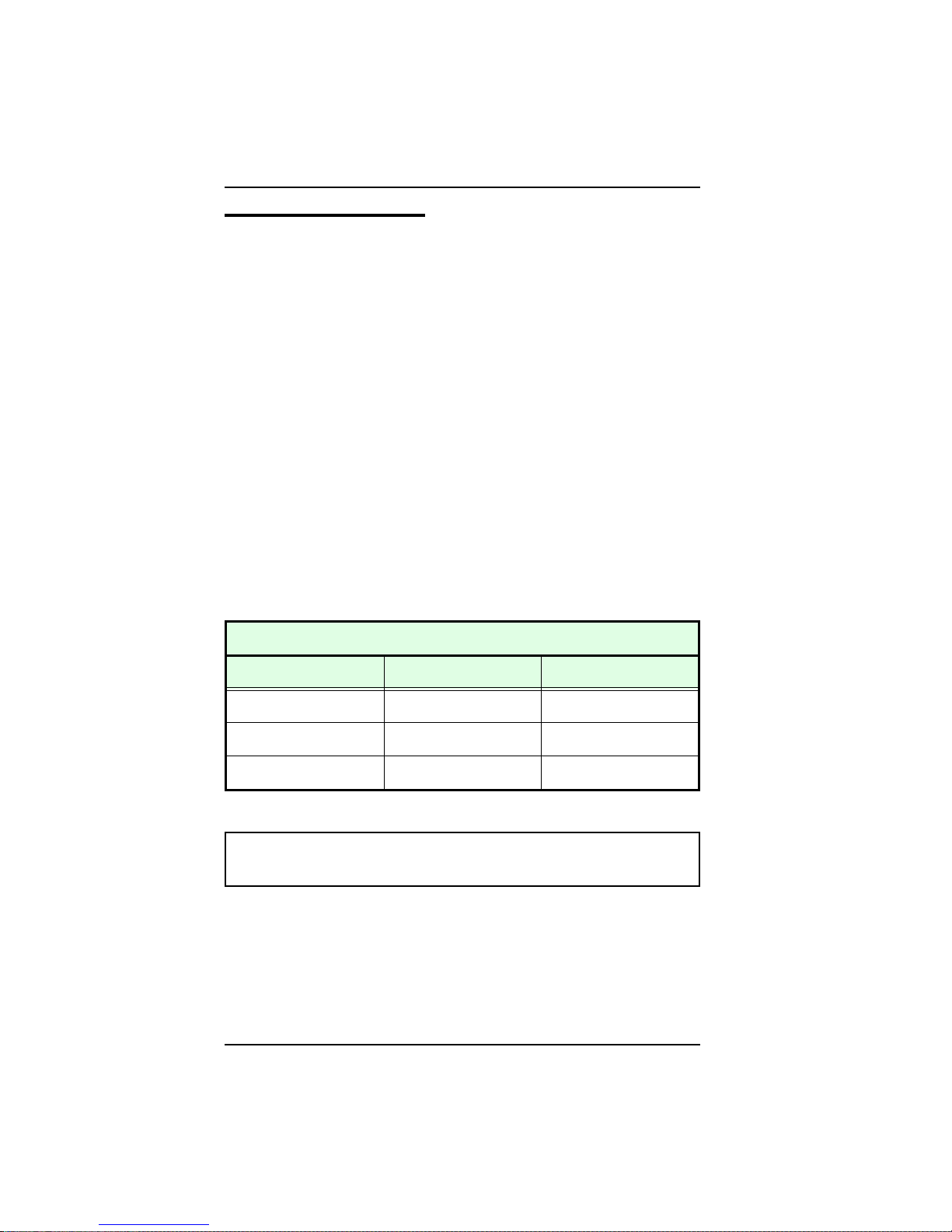
non-switched, three-pronged, grounded outlet. The following table lists the electrical
requirements for the Micro8:
Electrical Requirements for the Micro8
Requirement Domestic International
Voltage
Frequency
Power
CAUTION: Do not use a three-to-two-pronged adapter at the outlet.
Doing so may result in electrical shock and/or damage to the hub.
100 to 130 VAC 210 to 250 VAC
60Hz 50Hz
0.21 amps maximum 0.1 amps maximum
Spatial Requirements
The hubs dimensions are 4.0 x 7.0 x 5.0 inches (HWD). When you set the hub on a
level surface, allow at least 2 inches (5.1 centimeters) on each side of the hub for proper
air circulation. If you place the hub on a level surface, the rubber feet (attached to the
bottom of the hub) help protect the surface and prevent the hub from slipping.
2-2
Page 16
Connecting Power Setting Up the Micro8
Connecting Power
The domestic and international power connections differ for the Micro8. These
differences are described below.
Domestic Connections
To connect the Micro8 to external, domestic power, follow these steps:
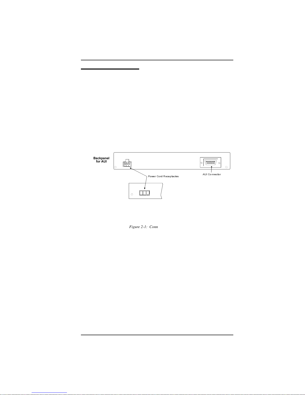
1. Locate the power cord receptacles on the back of the Micro8, as shown in Figure
2-1.
Backpanel
for AUI
AUI Connector
Backpanel for BNC,
UTP, and Basic
Power Cord Receptacles
Figure 2-1: Connecting the Power Cord
2. Plug the female connector of the power cord into the power cord receptacle on the
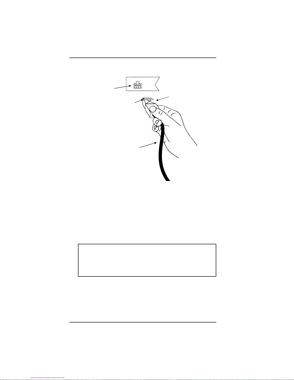
back of the hub. Be sure the lip (a horizontal tab) on the power connector faces
the top of the Micro8, as shown in Figure 2-2:
2-3
Page 17
Setting Up the Micro8 Connecting Power
Back of Micro8
Power
Receptacle
Lip of the Power
Connector
Power Module
Cable
Figure 2-2: Connecting Domestic Power
Female
Power
Connector
3. Insert the three-pronged, male connector on the other end of the power cord into
a non-switched, grounded power outlet on a wall, a power strip, or a grounded
extension cord. The power outlet should be near the hub and easily accessible
(within the 6-feet cord distance).
4. When you plug in the power cord, all LEDs on the front panel momentarily light
to confirm that the hub is operating correctly.
Note: When you power down the hub, disconnect the
three-pronged male connector from the power outlet on the wall,
power strip, or extension cord. DO NOT disconnect the female
connector from the power cord receptacle on the hub as this may
cause a power surge that could damage the hub.
2-4
Page 18
Connecting Power Setting Up the Micro8
International Connecti ons
To connect the Micro8 to external, international power, follow these steps:
1. Place the international power transformer on a flat surface.
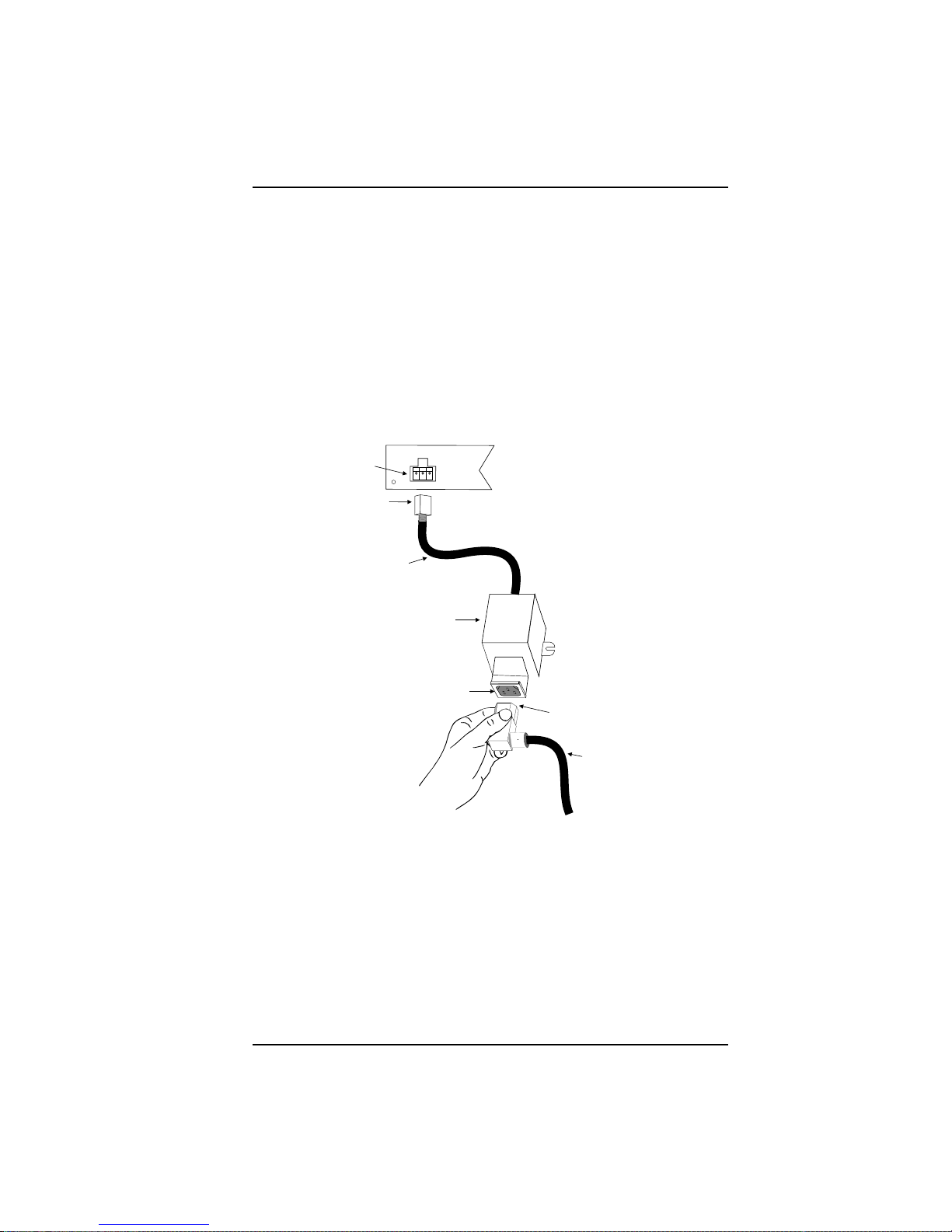
2. Plug the female connector on the power transformer cable into the power
receptacle in the back of the Micro8. Be sure the lip on the power connector faces
the top of the Micro8 (as illustrated for domestic connections in Figure 2-2).
3. Plug the female end of an IEC power cable into the three-pronged, power
transformer receptacle, as shown in Figure 2-3:
Back View of Micro8
Power
Receptacle
Female
Connector
Power
Transformer
Cable
Power
Transformer
Power
Transformer
Receptacle
Female End of
IEC Power Cable
IEC Power Cable
3-Pronged Male
IEC Connector
to a Grounded Receptacle
Figure 2-3: International Connections
4. Insert the three-pronged male connector on the IEC power cable into a grounded
power receptacle on the wall, a power strip, or a grounded extension cord.
5. After the power transformer is plugged in, be sure the LEDs light. If they do not,
recheck all connections.
2-5
Page 19

Setting Up the Micro8 Cabling Considerations
Cabling Considerations
This section outlines twisted-pair wire specifications and describes how to make a
simple direct connection between an Micro8 and a workstation.
Twisted-Pair Wire Specifications
To ensure long-term LAN reliability, be sure that the twisted-pair wiring meets the
following minimum specifications. If the wiring does not meet the following
requirements, you may need to install new twisted-pair wiring.
t The wiring must be shielded or unshielded twisted-pair (STP/UTP).
t Two pairs of wiring are required.
t Depending on building codes, different insulation materials may be required.
Plenum-rated or TEFLON-coated wiring may be required in some areas.
t The UTP wire should meet the following specifications:
l Solid copper
l Nominal capacitance: Less than 16pF/foot
l Nominal impedance: 100 Ohms
l Nominal attenuation: Less than 11.5db
l Wire gauge: Between 18 and 26 AWG (Most telephone installations use
24-gauge wiring.)
t The wiring has a maximum distance requirement of 100 meters which includes
all cross-connect wire, wire in the walls, and any drop cables from wall plates to
workstations (see the next section to determine the proper length). Maximum
distances may be less for UTP cable run underground, in conduit, or in large cable
bundles.
t The wiring must be in good condition and the insulation should not be frayed or
worn.
CAUTION: Never use gray satin station cable for connecting an
Micro8. This flat cable, typically used for connecting telephones to
wall jacks, is incompatible with 10BASE-T systems.
The Micro8 is compatible with all AT&T Type D wiring (D-Inside wiring) and AT&T
PDS wiring. You can also use IBM Type 1 wiring (with two inside conductors).
2-6
Page 20
Cabling Considerations Setting Up the Micro8
Two types of D-Inside wiring will work with the hub:
t DW8Uses stranded wires and is relatively flexible; is best for shorter runs (less
than 50 feet) within the same room
t D8WUses solid conductors and is less flexible; is best for longer runs through
ceilings and/or walls
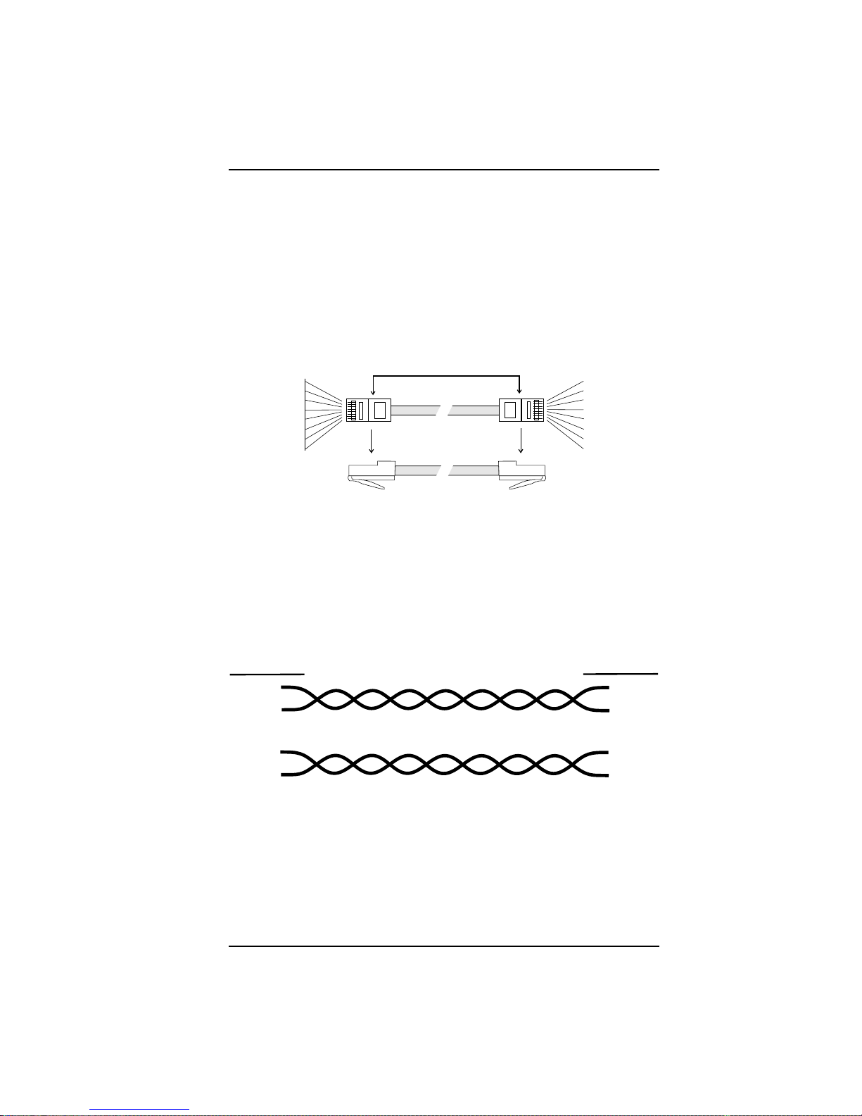
A modular cord is D-Inside wiring with RJ-45 plugs on each end. The connection
between a hub and a workstation consists of four pairs of straight-through, D-Inside
wiring (the hub uses only two pairs), as shown in the following figures:
Brown-White 8
White-Brown 7
Green-White 6
Blue-White 5
White-Blue 4
White-Green 3
Orange-White 2
White-Orange 1
Figure 2-4: D-Inside Wire
1 White-Orange
2 Orange-White
3 White-Green
4 White-Blue
5 Blue-White
6 Green-White
7 White-Brown
8 Brown-White
In this cable, the wire connected to Pin 1 must be twisted with the wire connected to
Pin 2, and the wire connected to Pin 3 must be twisted with the wire connected to Pin
6, as shown in Figure 2-3. Pins 4, 5, 7, and 8 are reserved for telephone and other
services.
Plug Pin #
1
2
Transmit Pair
Plug Pin #
1
2
Receive Pair
3
6
3
6
Figure 2-5: Receive/Transmit Pair
2-7
Page 21
Setting Up the Micro8 Cabling Considerations
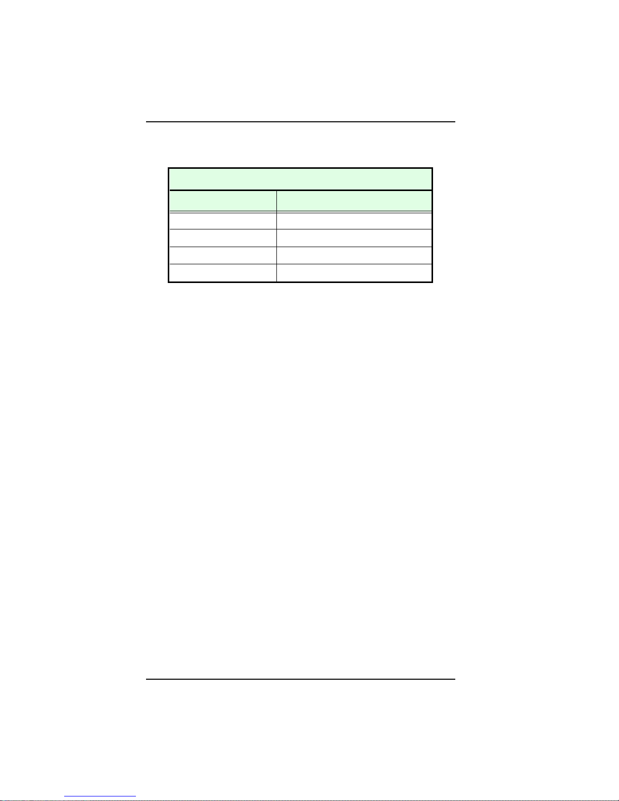
Each RJ-45 jack on the Micro8 has the following 10BASE-T standard pinout:
10BASE-T Standard Pinout
Pin Number Signal Descriptio n
1TD+
2TD3RD+
6RD-
A straight-through cable using the pair combinations shown above provides the
appropriate 10BASE-T connection between the hub and the workstation.
2-8
Page 22
Cabling Considerations Setting Up the Micro8
Hub-to-Workstation Connection
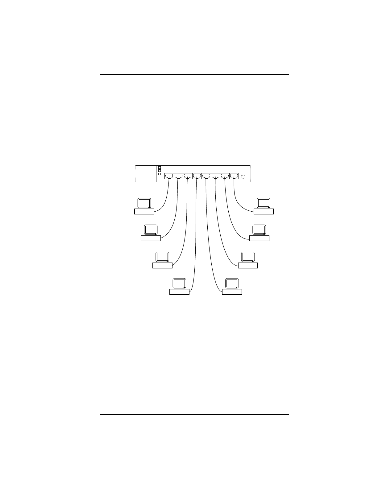
To connect the Micro8 to a workstation, follow these steps:
1. Plug one end of the modular cord into a 10BASE-T-equipped workstation.
2. Plug the other end of the modular cord directly into the desired port on the hub.
The maximum end-to-end cable distance is 100 meters.
After you connect the workstation to the hub and power on both units, the hubs
PWR LED and the LED that corresponds to the connected RJ-45 port should light.
If the LEDs do not light, verify that the connections are correct.
Figure 2-6: Hub-to-Workstation Connection
2-9
Page 23
Setting Up the Micro8 Setting the Uplink Switch
Setting the Uplink Switch
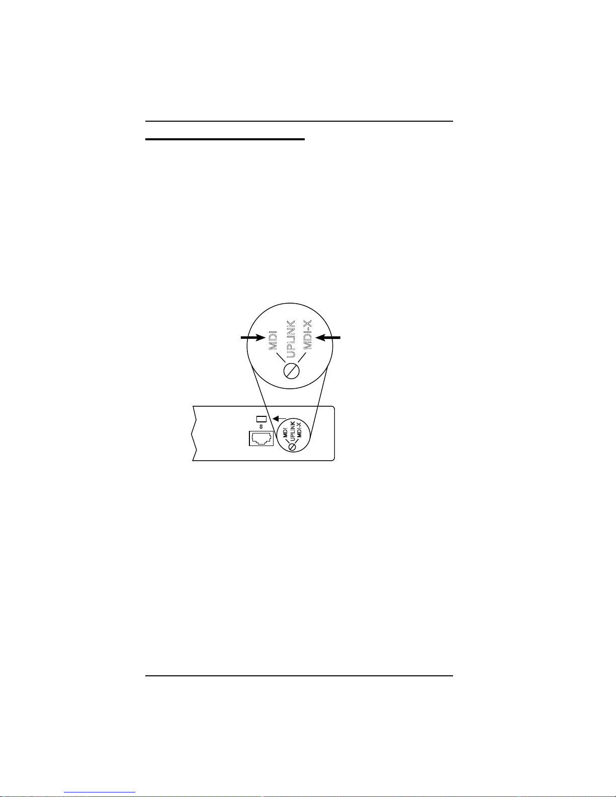
The uplink switch on the front panel of the Micro8 converts Port 8 to an uplinkable
port. This feature allows the hub to connect to another Micro8 in a star topology. The
default setting for the uplink switch is MDI-X (the standard RJ-45 port).
The uplink switch helps simplify twisted-pair wiring between Micro8s by
reconfiguring Port 8 as an output port and eliminating the need for crossover cables.
Typically, the Micro8s RJ-45 jacks function as input ports for workstation
connections. Connecting an input port from one hub to an input port of another hub
normally requires a special crossover cable that reverses the receive and transmit pairs.
To change the switch to the desired position, use a small, slotted screwdriver, or a
similar tool, shown in Figure 2-7.
Uplinkable
"OUT" Port
MDI
MDI-X
UPLINK
8
MDI
MDI-X
UPLINK
Figure 2-7: Setting the Uplink Switch
"IN" Repeater Port
Standard
(Default)
2-10
Page 24
Sample Network Configurations Setting Up the Micro8
Sample Network Configurations
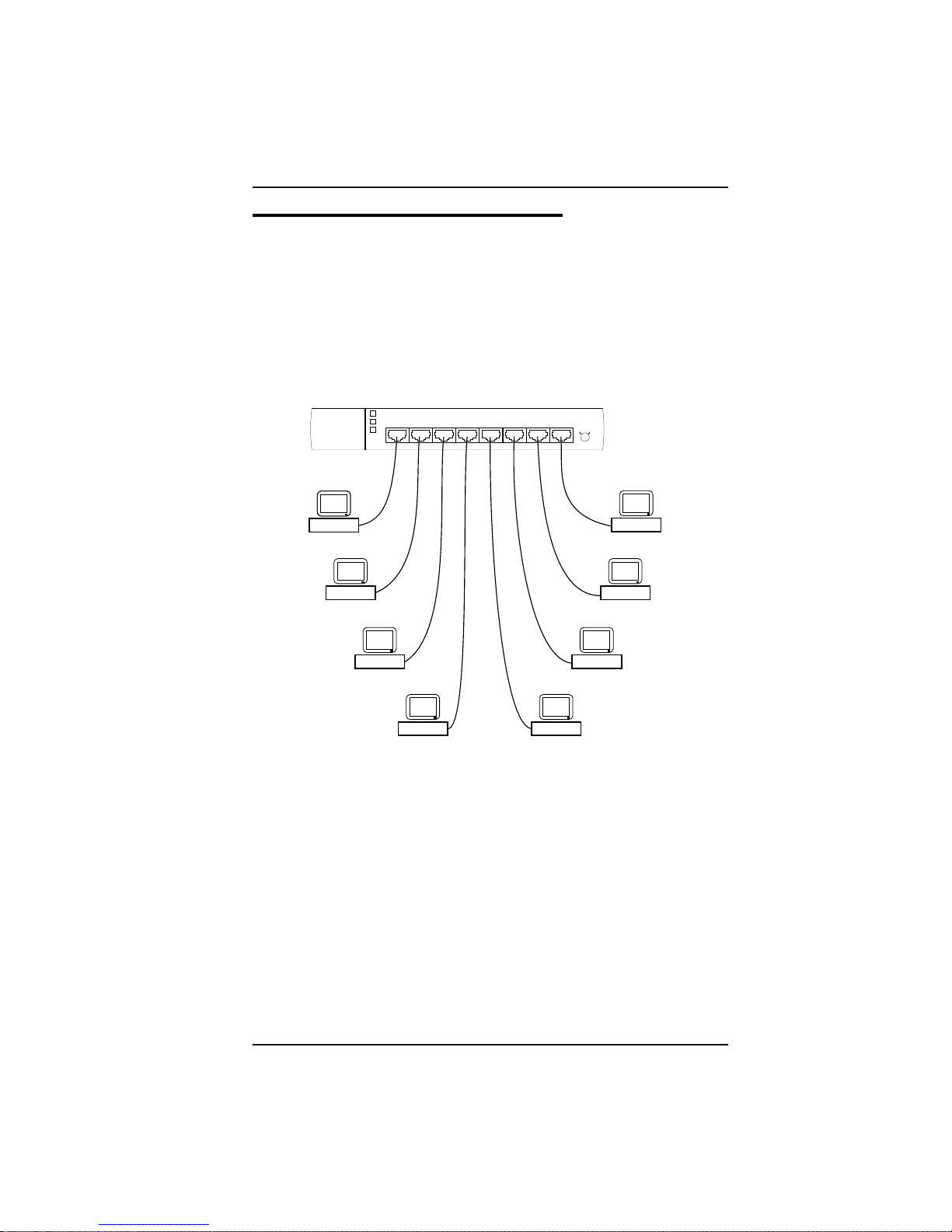
The following figures represent several network configurations for an Micro8 LAN.
Single Hub Configuration
Figure 2-8 shows one Micro8 connected to network stations within a 100 meter radius.
You can place the Micro8 in a wiring closet or next to network stations. In this example,
Port 8 of the Micro8 is configured as an input port to accommodate a workstation
connection.
Figure 2-8: Single-Hub Configuration
2-11
Page 25
Setting Up the Micro8 Sample Network Configurations
Multiple Hub Configuration
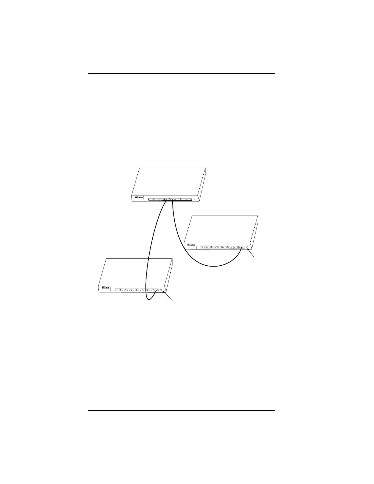
Figure 2-9 shows three Micro8s connected with unshielded twisted-pair wiring to form
a larger network.
t Micro8 A is the primary concentrator.
t Micro8 B and Micro8 C are uplinked to Micro8 A.
t Micro8 B and Micro8 C each have Port 8 configured as output ports.
Micro8 A
(Primary Concentrator)
Micro8 C
2-12
Micro8 B
UPLINK SWITCH
(MDI Position)
Figure 2-9: Multiple-Hub Configuration
UPLINK SWITCH
(MDI Position)
Page 26
Sample Network Configurations Setting Up the Micro8
Maximum Repeater Path Mod el
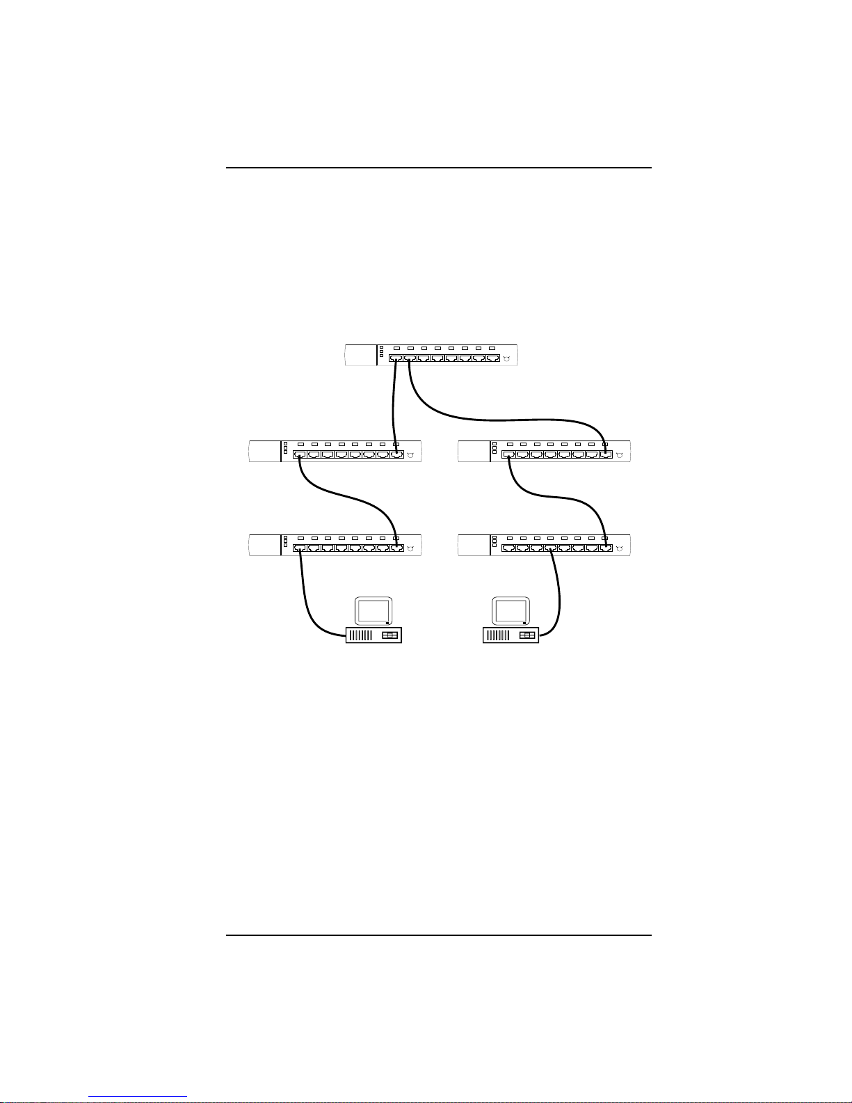
Ethernet limits the total number of repeaters that can be in the path between any two
network stations. The Micro8 allows up to five repeaters between any two nodes
(network stations). For a maximum configuration, you can use Micro8s to build a
network of up to 32 network stations. Figure 2-10 shows an example of a maximum
transmission path.
Hub 3
Hub 2
Maximum of Five Micro8s
Between Any Two Nodes
Figure 2-10: Maximum Repeater Path Configuration
Hub 4
Hub 5Hub 1
Node 1 Node 2
2-13
Page 27
Setting Up the Micro8 Sample Network Configurations
AUI Connections
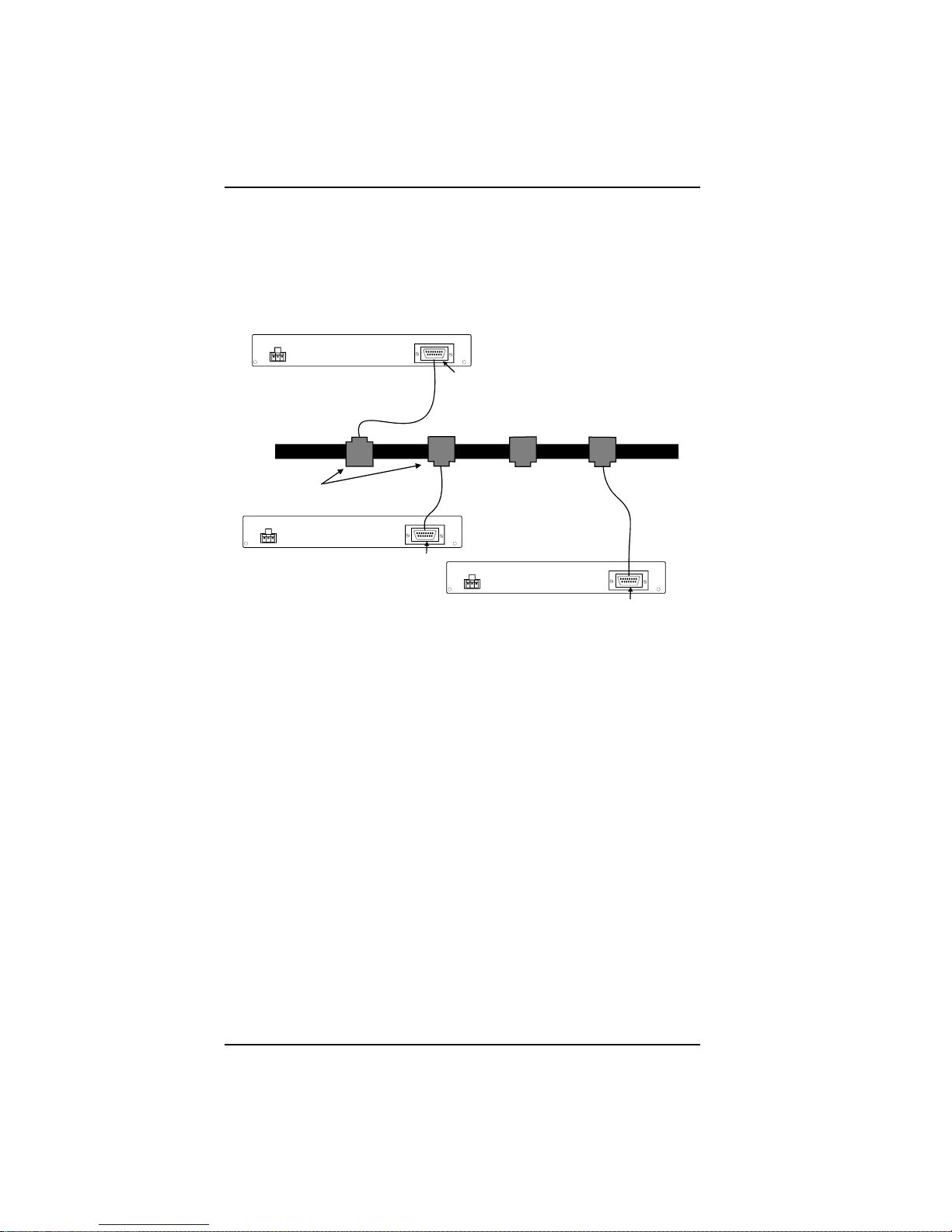
Figure 2-11 shows connections for the Micro8 using AUI to a 10BASE-5 backbone
LAN.
AUI Connector
10BASE-5 Backb one LAN
Transceivers
AUI Connector
AUI Connector
2-14
Figure 2-11: AUI Connections
Page 28
Sample Network Configurations Setting Up the Micro8
BNC Model
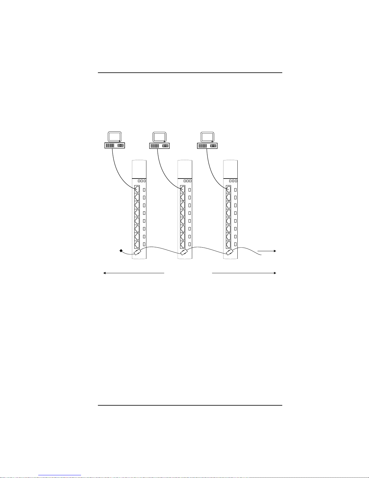
Figure 2-12 shows three Micro8s connected with thin Ethernet coax (RG-58) to form
a larger network. The total end-to-end length of this segment should not exceed 185
meters and must be terminated on each end with 50-ohm terminators.
50-Ohm
Terminator
Thin Coax
185 Meters Maximum
(End-to-End)
Figure 2-12: BNC Connections
To other
Concentrators
2-15
Page 29
Setting Up the Micro8 Sample Network Configurations
Thin Ethernet Co n nec ti o n s
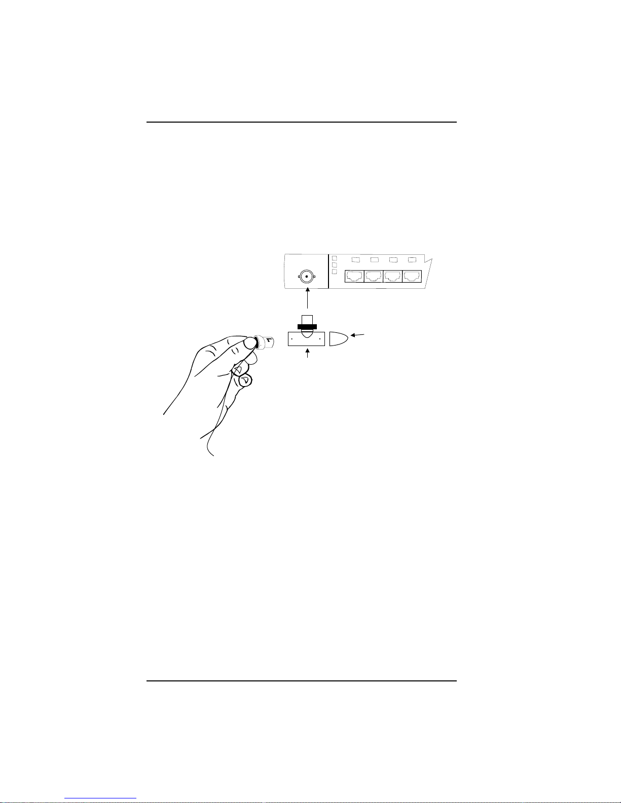
Figure 2-13 shows one Micro8 with a BNC connector for thin Ethernet connections.
You can use this BNC connector to connect to any thin Ethernet segment or to daisy
chain Micro8s.
To make the connection, use a T-connector, and, if the Micro8 is the last node on the
segment, terminate the T-connector with a 50-ohm terminator.
50-Ohm
Terminator
T-Connector
2-16
Figure 2-13: Ethernet Connections
Page 30

Glossary
10BASE-2 An IEEE Standard (802.3) for local area
networks. Complying networks must be able to
carry information at a rate of 10 megabit/second
over distances up to 185 meters of thin coaxial
cable
10BASE-5 An IEEE Standard (802.3) for local area
networks. Complying networks must be capable
of carrying information at a rate of 10
megabit/second over distances up to 500 meters
of thick coaxial cable
10BASE-T An IEEE Standard (802.3) for local area
networks. Complying networks must be able to
carry information at a rate of 10 megabit/second
over distances up to 100 meters of unshielded
twisted-pair cable.
66-Type Wiring
Environment
110-Type Wiring
Environment
802.3 An IEEE standard for Ethernet local area
Adapter A device that supports the interconnection of
Attachment Unit
Interface (AUI)
Also called Premises Distribution System
(PDS). The AT&T wiring system in which the
telephones, nodes and other communications
devices connect to the cross-connect block
Also called Premises Distribution Systems
(PDS). The AT&T wiring system in which the
telephone, nodes and other communications
devices can be easily added and rearranged with
modular wiring components and patch cords
networks based on Carrier Sense Multiple
Access with Collision Detection (CSMA/CD),
which includes 10BASE2, 10BASE 5 and
10BASE-T
different sizes and/or types of plugs
The interface between the medium attachment
unit (MAU) and a node within a local area
network (LAN)
Glossary - 1
Page 31

Glossary Series 1000 Micro8 Hub
Backplane The data bus connections that interconnects
different communication modules inside a
network concentrator
BNC A thin Ethernet coax connector
Bridged Tap (Stub) A cable (or cord) connected to another cable (or
cord) at a point other than its end. Such a tap
causes impairment of network signal
transmissions
Carrier Sense The monitoring of a local area network by a node
to determine if another node is transmitting
Coaxial Cable A cable with at least one transmission line
consisting of two conductors, an inner conductor
and an outer conductor, insulated from one
another by a dielectric. Coaxial cable carriers
higher frequencies than twisted pair cable and
offers a broader bandwidth. It commonly
transmits video signals, but can also be used for
certain high-speed data applications.
Collision A condition that occurs when two nodes attempt
to transmit on the network at the same time.
When a collision occurs, both nodes recognize
the collision, stop transmission, wait for a
random time interval, and then attempt to
retransmit.
Concentrator A device that provides connectivity between data
terminals in a network
Conductor A medium, such as copper wire, that can carry
electrical current
Configuration The layout of nodes and components in the
network
Cross-Connect Block A panel on which the leads of station cable are
mounted so a technician, other wiring crafts
person, or a system administrator can make
connections between the communications
devices wired to the cables
DCE Data Communications Equipment
DTE Data Terminal Equipment
Glossary - 2
Page 32

Series 1000 Micro8 Hub Glossary
Dielectric A substance that does not conduct electrical
current
Ethernet Transceiver A device used in an Ethernet local area network
that couples data terminal equipment to other
transmission media
Fiber Adapter A hardware device that converts System 4000
network signals between electrical signals on
twisted-pair wire and light pulses transmitted on
fiber optic cable
Fiber Optic Cable A transmission medium consisting of a core of
glass surrounded by strengthening material and a
protective jacket. Signals are transmitted as light
pulses and introduced into the optical fiber by a
laser or light emitting diodes (LEDs).
Jabber A condition where the transmission of network
signals exceeds the maximum allowable
transmission time. Jabber may be caused by a
faulty node or wiring connection.
LED Light Emitting Diode
Link Integrity A diagnostic tool that continuously checks wiring
for breaks, opens or shorts, and notifies the user
if those conditions exist
Local Area Network
(LAN)
A data communications network consisting of
electronic devicessuch as host computers, file
servers and personal computersoften
connected via twisted-pair wire or coaxial cable.
Typically, the network is limited to a single
premise.
Medium Attachment
Unit (MAU)
A device used in a data station to couple the data
terminal equipment (DTE) to the transmission
medium
Megabit One million bits
Modular Cord A cord containing four twisted pairs of wires with
a modular plug on one or both ends.
Module The component that provides connectivity ports
for the LAN. Modules are installed in larger
systems called concentrators.
Glossary - 3
Page 33

Glossary Series 1000 Micro8 Hub
Network Interface Card
(NIC)
A plug-in expansion board that enables
computers to send and receive data through the
network
Node A computer, workstation or other device in a
network
Partition The disconnecting of a node from a LAN
Plenum Cord A communications cord with fire-retardant
insulation, generally used in suspended ceilings
and other places where air circulates back to the
buildings air-conditioning system.
Port A concentrator connection that connects PCs and
other node devices to the network
Primary Hub
(Concentrator)
The hub in a room or wiring closet to which all
other hubs are connected. If a room or a wiring
closet has only one hub, it also is considered a
primary hub.
Satellite Closet A room where cross-connect hardware is located
and where cabling from wall jacks is terminated
Secondary Hub
(Concentrator)
Any hub whose OUT jack is connected to an IN
jack of a primary hub in the same room or wiring
closet
Telco A 25-pair, polarized connector that consolidates
multiple voice or data lines
Terminators Devices that are used at the ends of networks to
electrically balance the cabling to ensure that
signals dont reflect or become distorted (thin
Ethernet uses 50-ohm terminators)
Tip/Ring System The AT&T wiring environment that designates
tip and ring as the functions of two conductors
within each wire group of a 25-pair station cable
Transceiver Cable A cable that connects two hardware devices, one
having a D-type DCE connector and the other
having a D-type DTE connector. Also called an
AUI cable.
Glossary - 4
Page 34

Series 1000 Micro8 Hub Glossary
Unshielded Twisted Pair
(UTP) Wire
Two insulated copper wires twisted together to
reduce the potential for signal interference
between pairs. In cables greater than 25 pairs, the
twisted pairs are grouped and bound together in a
common cable sheath. Twisted pair cable is the
most common of transmission media.
Wiring Environment Any building communications wiring system.
See 66-Type Wiring Environment.
Wiring Closet A room, closet or cabinet where station cable is
terminated on cross-connect blocks and where
the building communications system can be
administered
Glossary - 5
Page 35

Index
A
ACT, 1-5
Altitude, 2-2
B
BNC, length requirements, 2-15
C
COL LED, 1-5
Configurations
AUI, 2-14
BNC, 2-15
Hub-to-workstation, 2-9
Maximum repeater path, 2-13
Multiple hub, 2-12
Single hub, 2-11
Cooling, 1-2
Crossover cables, 2-10
D
F
Frequency, 2-2
G
Gray satin cable, 2-6
Grounded power outlet, 2-4
H
Humidity, 2-2
I
IEC power cable, 2-5
IEEE 802.3, 1-1
International electrical requirements,
2-2
International power connections, 2-5
L
D-Inside wiring, 2-7
D8W, 2-7
Dimensions, 1-2
Domestic electrical requirements, 2-2
Domestic power connections, 2-3, 2-5
DW8, 2-7
Electrical requirements, 2-2
Ethernet connections, 2-16
LEDs, 1-1, 2-9
At startup, 2-4
Colors, 1-5
Link status, 1-5
List of, 1-2
Location of, 1-5
Link integrity, 1-1
E
Index - 1
Page 36

Index
M
Maximum wiring distance, 2-6
MDI-X, 2-10
O
Operating environment, 1-2, 2-2
P
Part numbers, i-vii
Power connection distance, 2-4
Power consumption, 1-3
Power requirements, 2-2
Power transformer, 2-5
PWR LED, 1-5
R
Repeaters
Maximum number of, 2-13
RG-58 thin coax, 2-15
RJ-45, 1-1, 2-7 - 2-8, 2-10
U
Uplink switch, 2-10
UTP specifications, 2-6
V
Voltage, 2-2
W
Wiring insulation, 2-6
S
Spatial requirements, 2-2
Specifications, 1-2 - 1-4
Storage environment, 1-2
T
T-connector, 2-16
Temperature, 2-2
Transformer, 2-5
Twisted-pair wiring specifications
List of, 2-6
Index - 2
Page 37

707084-002
3/95
 Loading...