

Page 1
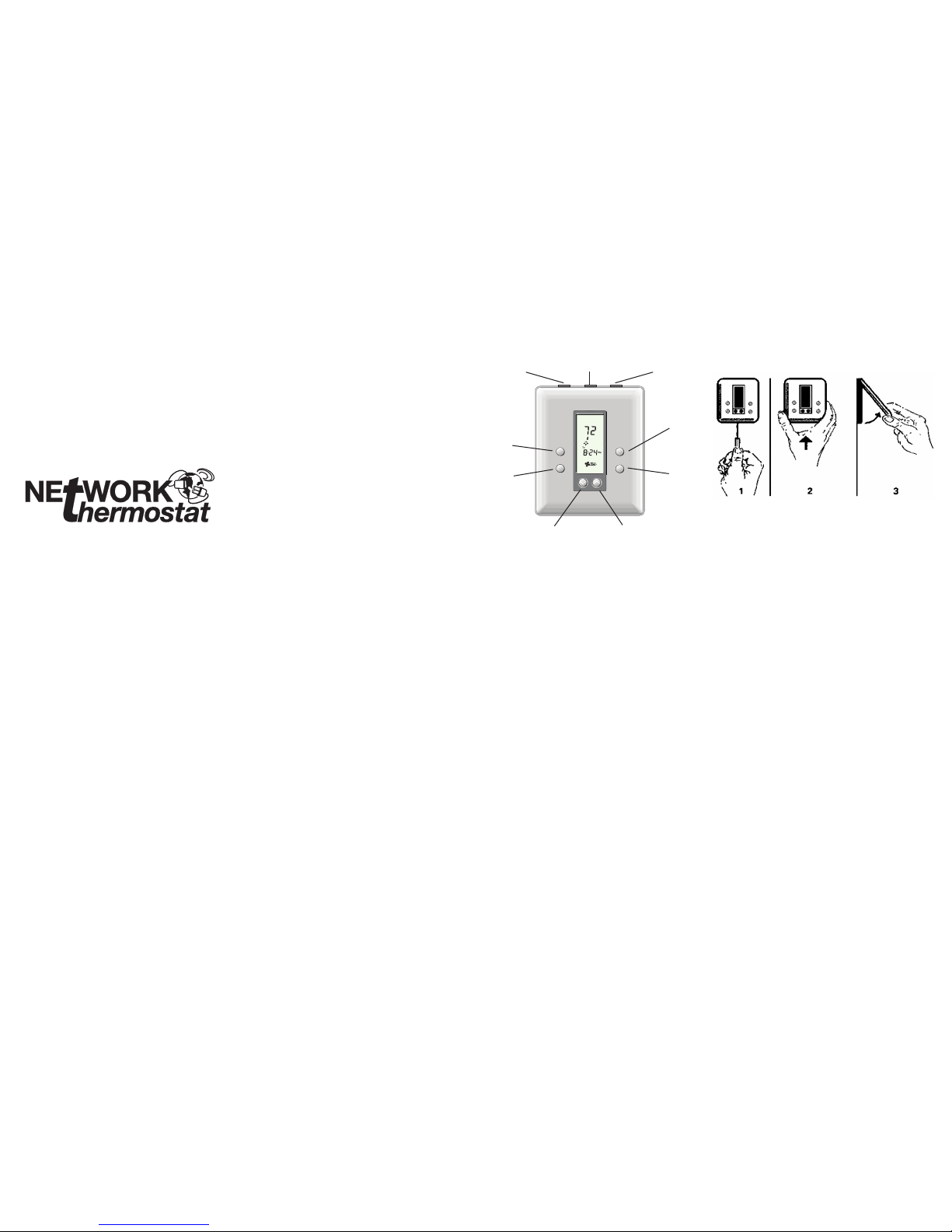
REMOVING THE THERMOSTAT FROM
THE BACKPLATE
1. Insert a at blade screwdriver or coin 1/8” into the slot located
in the bottom center of the thermostat case and twist 1/4 turn.
When you feel or hear a click, grasp the case from the bottom
two corners and separate from the backplate as shown in the
diagram at the left. Some models require more force than
others when separating due to the number of terminals used.
2. Swing the thermostat out from the bottom.
3. Lift the thermostat up and off the backplate.
4. Place the rectangular opening in the backplate over the
equipment control wires protruding from the wall and, using
the backplate as a template, mark the location of the two
mounting holes. NOTE: If adding the wireless backplate
(WBM-1 or WBM-WiFi), simply discard the backplate which
came with the thermostat. The wiring instructions for the
equipment are identical.
5. Use the supplied anchors and screws for mounting on drywall
or plaster; drill two 3/16” (5mm) diameter holes at the marked
locations; use a hammer to tap the nylon anchors in ush
to the wall surface and fasten backplate using the supplied
screws. (Do not over tighten!)
6. Connect the wires from your system to the thermostat
terminals as shown in the wiring diagrams. Carefully dress
the wires so that any excess is pushed back into the wall
cavity or junction box. Ensure that the wires are ush to the
plastic backplate. The access hole should be sealed or
stuffed to prevent drafts from affecting the thermostat.
BUTTON OPERATION
THERMOSTAT LOCATION
To ensure proper operation, the thermostat should be mounted
on an inside wall in a frequently occupied area of the space.
In addition, its position must be at least 18” (46 cm) from any
outside wall, and approximately 5’, (1.5 m) above the oor in a
location with freely circulating air of an average temperature.
Be sure to avoid the following locations:
• Behind doors or in corners where freely circulating air is
unavailable
• Where direct sunlight or radiant heat from appliances might
affect control operation
• On an outside wall
• Adjacent to, or in line with, conditioned air discharge grilles,
stairwells or outside doors
• Where its operation may be affected by steam or water pipes
or warm air stacks in an adjacent partition, or by an unheated/
uncooled area behind the thermostat
• Where its operation may be affected by lighting dimmers
next to it
• Where its operation will be affected by the supply air of an
adjacent unit
• Near sources of electrical interference such as arcing
relay contact
INTRODUCTION
The RP32-NX Programmable Thermostat represents the most
advanced solid-state, microcomputer temperature control on
the market today. The thermostat incorporates state-of-the-art
technology packaged in an extremely low prole designer
series case. Integrated with the Net/X™ XBus communications
port, the RP32-NX is positioned to allow either wired (XBus),
wireless StrongMesh™ (802.15.4), or wireless WiFi (802.11) set
up and communications. The Ultra-Touch push-buttons are
combined with an easy-to-read, full function liquid crystal display
to provide the ultimate in user friendly operation of your heating
and air conditioning equipment, including gas, electric, oil and
heat pump controls.
STANDARD FEATURES
• No batteries required – always remembers scheduled events
and temperatures
• Computerized heat anticipation and cooling drop
• Intelligent Fuzzy Logic staging for efcient operation of
equipment, including auxiliary heat
• Built-in short cycle equipment protection during normal
operation
• Tamper proof electronic keyboard lockout with programmable
override ranges
• Automatic, manual and recirculation fan operation
• Auto or manual heat/cool changeover
• Vacation hold feature allows extended override with return day
and time
• Temporary schedule override with automatic schedule return
• Selectable 12 or 24 hour clock display
(Communication Interface only)
• Selectable Fahrenheit or Celsius temperature display
• Integrated XBus™ Communications for programming via
computer, web and smart phone
Installation and Programming
Instructions for
RP32-NX
Residential Programmable Thermostat
with XBus™ Communications
www.networkthermostat.com
TABLE OF CONTENTS
INTRODUCTION . . . . . . . . . . . . . . . . . . . . . . . . . . . . . . . . . . . . . 2
BUTTON OPERATIONS . . . . . . . . . . . . . . . . . . . . . . . . . . . . . . . . 2
THERMOSTAT LOCATION . . . . . . . . . . . . . . . . . . . . . . . . . . . . . . 3
REMOVING THE THERMOSTAT FROM THE BACKPLATE . . . . . 4
DESCRIPTION OF THE DIP SWITCH FUNCTIONS . . . . . . . . . . 5
FEATURES AND SETTINGS . . . . . . . . . . . . . . . . . . . . . . . . . . . . 6
COVER LOCK . . . . . . . . . . . . . . . . . . . . . . . . . . . . . . . . . . . . . . . 7
REPLACING THE THERMOSTAT ON THE BACKPLATE . . . . . . . 7
BUTTON PRESS COMBINATIONS . . . . . . . . . . . . . . . . . . . . . . . 8
TEMPERATURE OVERRIDE . . . . . . . . . . . . . . . . . . . . . . . . . . . . 9
VACATION OVERRIDE. . . . . . . . . . . . . . . . . . . . . . . . . . . . . . . . . 9
CHANGING FAHRENHEIT (°F) TO CELSIUS (°C) . . . . . . . . . . . . 9
CHANGING 12 HOUR TIME TO 24 HOUR TIME . . . . . . . . . . . 10
POWER FAILURES . . . . . . . . . . . . . . . . . . . . . . . . . . . . . . . . . . 10
OUTDOOR TEMPERATURE INDICATOR . . . . . . . . . . . . . . . . . 10
PROGRAMMING THE THERMOSTAT . . . . . . . . . . . . . . . . . . . . 10
COMMUNICATIONS CONNECTION TO THE THERMOSTATS . 11
WIRING DIAGRAMS . . . . . . . . . . . . . . . . . . . . . . . . . . . . . . . 11-20
SPECIFICATIONS . . . . . . . . . . . . . . . . . . . . . . . . . . . . . . . . . . . 21
SENSOR FAULTS . . . . . . . . . . . . . . . . . . . . . . . . . . . . . . . . . . . 22
WARRANTY . . . . . . . . . . . . . . . . . . . . . . . . . . . . . . . . . . . . . . . . 23
Mode
Vacation
Fan
Resume
Press to Select
Heat/Cool/Auto/Off.
The word is displayed
for 5 seconds.
Press to Raise Setpoint or
increase numeric values.
Press to Resume
Normal Schedules.
Press to Set a
Vacation Override.
LED2 (YELLOW)
Press to Lower Setpoint or
decrease numeric values.
Press for Selection of
Fan Auto, Fan On, or
Recirculation Fan.
LED3 (RED)LED1 (GREEN)
TM
2 3 41
Page 2
BUTTON PRESS COMBINATIONS
Single Press
• MODE Changes from HEAT to COOL to AUTO
to OFF.
• FAN Sets the fan ON (continuous), or AUTO
(operates with the equipment), or CIRC
(recirculation).
• RESUME Cancels Temporary or Vacation overrides
and resumes normal operating schedule.
• VACATION Starts the Vacation (or extended) override.
• UP Increments the blinking numerical or icon
segments of the display.
• DOWN Decrements the blinking numerical or icon
segments of the display.
Multi-Press
• UP & DOWN Toggles between °F and °C.
• RESUME & Displays Outdoor Temperature
VACATION (if thermostat is connected to the internet)
for 30 seconds.
Press and Hold (for 12 seconds)
• MODE Resets the thermostat to factory defaults.
Press and hold the MODE button for 12
seconds to evoke the number of resets.
Press the MODE button a second time to
reset the defaults.
NOTE: All schedules will be reset.
• FAN Enters thermostat sensor de-calibration
mode. Allows a temperature offset of up
to +/-3°F. To remove the de-calibration,
press and hold the MODE button.
• MODE & FAN Enter Address Mode (change thermostat
communications address)
• RESUME & Allows for adjustment of High and Low
MODE balance points when displaying outdoor
temperature (hold for 5 seconds).
NOTE: The thermostat must be connected
to the internet for this feature to be available.
• FAN & VACATION Sets desired time period for a temporary
temperature override.
FEATURES AND SETTINGS, con’d
Override Timer Conguration
You will be able to adjust the length of a temporary override
condition from 15 minutes to 8 hours, in 15 minute increments.
To display/set the Override time, press and hold the FAN and
VACATION buttons for 12 seconds, then press the UP or DOWN
button. Future ‘overrides’ to the schedule will hold the setpoint
for the desired time and then return to the pre-programmed
schedule.
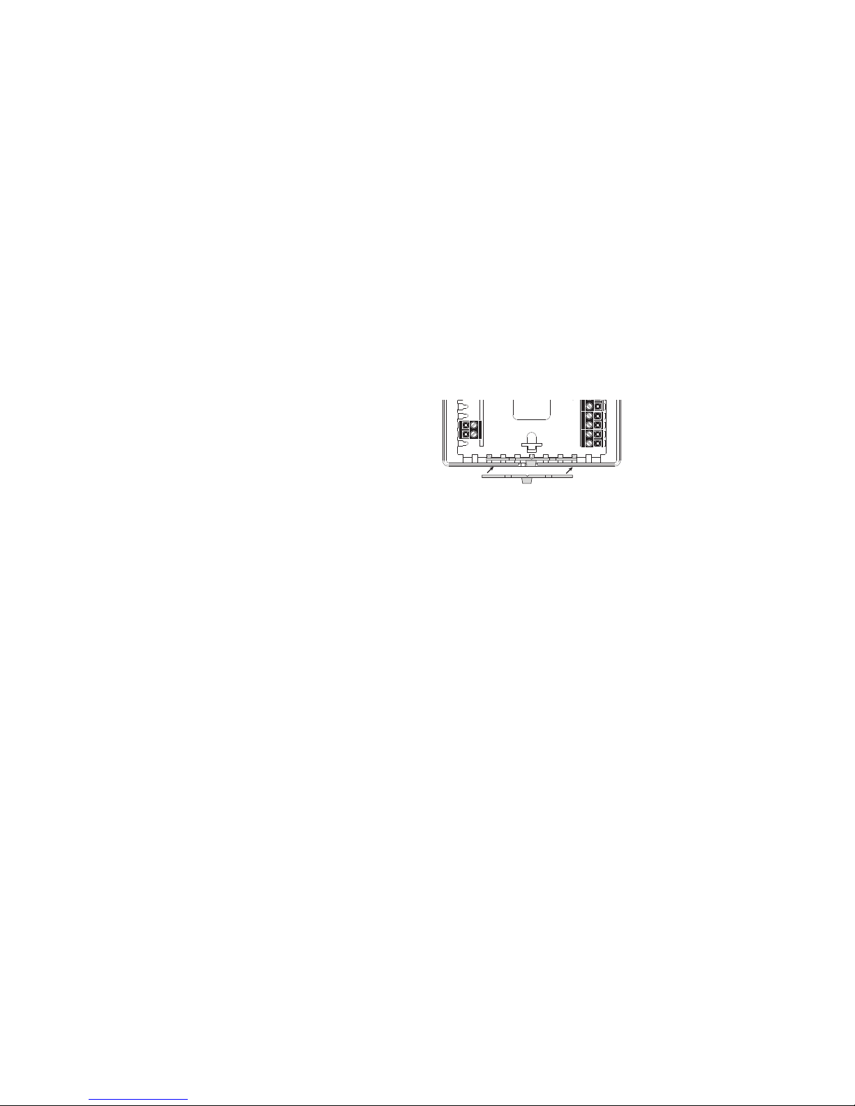
COVER LOCK
You also may lock the cover down to prevent unauthorized access to the thermostat by adding the clear plastic lock (included
in the installation bag). To install, remove the thermostat from
the backplate and place the clear plastic lock in the backplate
as shown below. Replace the thermostat and close the cover.
The cover now is locked. To open, simply use a screwdriver
to carefully push the lock back, allowing the cover to open. To
remove the lock, open the cover, remove the thermostat from the
backplate, and then remove the lock.
REPLACING THE THERMOSTAT ON
THE BACKPLATE
1. Position the thermostat on the hinged tabs located at the top
of the backplate.
2. Gently swing the thermostat down and press on the bottom
center edge until it snaps in place.
FEATURES AND SETTINGS
LED #1 (GREEN): Filter Indicator
The green (left) LED may be used together with the FILTER icon
to indicate the HVAC system’s air lter(s) need to be changed.
LED #2 (YELLOW): Service Indicator
The yellow (right) LED may be used together with the WRENCH
icon to indicate there is a problem with the HVAC system.
LED #3 (RED): Auxiliary/Emergency Heat Indicator
The red (center) LED will illuminate when the thermostat has
engaged a heat pump system into either auxiliary heat mode or
emergency heat mode.
Note: The green, yellow and red LEDs may also be used to
indicate Off-Peak, Mid-Peak and On-Peak time of use (TOU)
energy rate pricing plans as dened by your electric utility
provider. This feature is only available when the thermostat is
connected via communications to your utility company’s network.
While NetworkThermostat has included these LEDs to be
accessible by utility companies, use of this feature may require
upgraded rmware or communications hardware, yet to be
dened by NetworkThermostat or your utility company.
Add-On (Dual-Fuel) Heat Pump Control
If needed, the thermostat will perform the function of a fossil
fuel kit. When in this mode, the thermostat will turn off the
compressor with a call for AUX heat. When Switch 1 and
Switch 5 are in the ON position, the thermostat allows the
compressor and the AUX heat to be on simultaneously.
Random Restart
After a power failure, the thermostat will delay the heating/
cooling equipment start-up by 8-40 seconds. When multiple
Net/X™ RP32-NX thermostats are used, this minimizes the ‘in
rush’ current (electric power usage) as it reduces the number of
HVAC units that will be turned on simultaneously.
High & Low Balance Point Conguration
If the thermostat is being used as a Heat Pump thermostat
(Dip Switch #1 in the ON position), and outdoor temperature
information is available by using an Internet connection, the
thermostat can be congured to disable the use of auxiliary
heat during warmer weather and to lock out the compressor
during colder weather.
To display/set the High and Low balance points:
1. Press RESUME and VACATION together to show the outdoor
temperature.
2. Press and hold the MODE and RESUME buttons for 5 seconds
to evoke the High and Low balance point temperatures.
The display will indicate the high or low balance point and the
selected temperature. Press the UP or DOWN button to adjust
the balance point temperature. Pressing the MODE button again
will toggle to the alternate balance point.
NOTE: Refer to the heat pump equipment manual for
temperature cut-offs on the equipment.
DESCRIPTION OF THE DIP SWITCH FUNCTIONS
DIP Switch 1: GE/HP Operation
Place DIP Switch 1 in the OFF position for Gas/Electric furnace
operation.
Place DIP Switch 1 in the ON position for Heat Pump operation.
DIP Switch 2: Adaptive Setpoint Recovery
Place DIP Switch 2 in the OFF position for Adaptive Setpoint
Recovery operation. When this is enabled, the thermostat will
anticipate when to turn on the heating or cooling system prior to
the start of a schedule in order to achieve the desired setpoint
temperature by the beginning of the schedule.
DIP Switch 3: 2 Minute or 4 Minute Minimum On/Off Times
When DIP Switch 3 is in the ON position, the minimum ON/OFF
time is 2 minutes. The system will operate for a minimum of 2
minutes or 4 minutes, and allow equipment recovery for 2 or 4
minutes before turning on again. This is also known as short
cycle protection.
DIP Switch 4: Unlocked/Locked Keypad
When DIP Switch 4 is in the ON position, all buttons are disabled
with the exception of the UP, DOWN and MODE button. Users
will be restricted to either a +/-3°F or +/-5°F range from the
scheduled setpoints as dened by Dip Switch #7 for the
programmed override time. Users will still be able to cycle
between HEAT and COOL.
DIP Switch 5: Plenum Fan Switch /Add-On Heat Pump
DIP Switch 5 is used to determine when the fan needs to be
turned on.
Place DIP Switch 5 to OFF and DIP Switch 1 to OFF to have the
fan turn on immediately when there is a call for heat. (Required
with electric heat.)
Place DIP Switch 5 to ON and DIP Switch 1 to OFF to have the
plenum switch operate the fan.
Place DIP Switch 5 to OFF and DIP Switch 1 to ON for normal
heat pump operation.
Place DIP Switch 5 to ON and DIP Switch 1 to ON for Add-On
(Dual-Fuel) Heat Pump operation.
DIP Switch 6 :
Multi-Stage System Operation Place DIP Switch 6 to OFF
position for single-stage applications.
(single-stage compressors and heaters)
Place DIP Switch 6 to ON position for multi-stage applications.
(two-stage compressors and heaters)
DIP Switch 7 : Temporary Override Adjustment Range
Place DIP Switch 7 to OFF to limit temporary adjustments to
+/- 3°F.
Place DIP Switch 7 to ON limit temporary adjustments to +/- 5°F.
DIP Switch 8 : Not Used
Keep OFF.
6 7 85
W1
Y1
G
R
24V
24V (c)
O/W2
B
X2
X1
Page 3

COMMUNICATIONS CONNECTION TO THE
THERMOSTAT
Communications connections to the thermostat may be
accomplished using the following options.
1. WBM-WiFi (802.11 compliant) Wireless Backplate
2. WBM-1 (802.15.4 compliant) StrongMesh™ Mesh Network
Wireless Backplate
3. Net/X™ Wired XBus Converter
CHANGING 12 HOUR TIME TO 24 HOUR TIME
This thermostat is preset to display the standard 12 hour time
format. You may change the display to the 24 hour time format.
NOTE: This feature is available through the communications
interface.
POWER FAILURES
This Net/X™ thermostat product will maintain the program
settings during any type of power failure. If power fails, AC will
be displayed for 30 minutes. After 30 minutes, the display will
go blank. If power is restored within the rst 30 minutes, the
thermostat will resume normal operation. If power is restored
after 30 minutes, 12:00 AM will ash, and the thermostat will
control to the night event setpoint until the clock is reset.
Once the clock is reset, the thermostat will resume normal
programmed operation.
OUTDOOR TEMPERATURE INDICATOR
(OPTIONAL)
If your Net/X™ thermostat is connected to the Internet, you can
view the outdoor temperature by simply pressing and holding
RESUME and VACATION buttons simultaneously.
PROGRAMMING THE THERMOSTAT
This Net/X™ thermostat product has factory default programs
as indicated below. Based on EnergyStar® guidelines and
recommendations, these settings can reduce heating/cooling
expense by as much as 33%.
DEFAULT
SCHEDULES
Heat
(Mon-Fri)
Cool
(Mon-Fri)
Heat
(Sat-Sun)
Cool
(Sat-Sun)
Morning
(Sched 1)
70°F 78°F 70°F 78°F
Day
(Sched 2)
62°F 85°F 62°F 85°F
Evening
(Sched 3)
70°F 78°F 70°F 78°F
Night
(Sched 4)
62°F 82°F 62°F 82°F
This thermostat is intended to be used as a Communicating
Programmable Thermostat, with changes to the thermostat
schedules accomplished over a computer interface, using any of
four options.
1. Personal computer using the Net/X™ Command Center
software.
2. Personal computer using Internet Explorer, Safari or Firefox
web browser (allows use of the integrated web server in the
WBM-WiFi backplate).
3. Custom software using the Net/X™ ASCII protocol, allowing
integration into any application.
TEMPERATURE OVERRIDE
Temporary Override (15 minutes to 8 hours)
You may change the temperature setting temporarily at any time
without affecting the program.
• Press the UP or DOWN buttons. The current event temperature
and mode of operation will be displayed.
• Press the UP or DOWN buttons again to adjust the temperature.
This temperature will be maintained for the pre-programmed
amount of time.
• To cancel, simply press the RESUME button.
Temporary Override with Keyboard Locked
(15 minutes to 8 hours)
You may change the temperature setting temporarily at any
time without affecting the program, even though the keypad
is locked.
• Press the UP or DOWN buttons. The display will show the
temperature for the rst event.
• Press the UP or DOWN buttons again to adjust the
temperature +/-3°F or +/-5°F degrees. This temperature
will be maintained for the pre-programmed amount of time.
• To cancel, simply press the RESUME button.
VACATION OVERRIDE
A Vacation Override may be set from 1 - 99 days. To set a
Vacation Override:
1. Press and release the VACATION button.
2. Press the UP or DOWN button to set the number of days until
returning. The Day of Week icons will cycle with each press of
the UP or DOWN button, indicating the return day.
3. Press and release the VACATION button again. The display
will change to 12: with PM blinking.
4. Press the UP or DOWN button to set the planned hour you
are returning.
5. Press the VACATION button again. The display will change to
:00 blinking.
6. Press the UP or DOWN button to set the minutes in 10 minute
increments.
7. Press the VACATION button to accept the hold program.
8. Use the MODE button to select the Mode (Heat, Cool, Auto,
Off) during the Vacation Override.
9. Use the UP and DOWN buttons to set the desired Heating and
Cooling setpoints for use during the Vacation override.
NOTE: Steps 8 and 9 may be performed either before or after
setting the Vacation Override.
CHANGING FAHRENHEIT (°F) TO CELSIUS (°C)
This thermostat is preset to display the temperature in Fahrenheit.
You may change the display to Celsius. To change from one to
the other, simultaneously press the UP and DOWN buttons. The
display will change automatically.
EQUIPMENT WIRING DIAGRAM : RP32-NX
Generic Connections
HVAC CONNECTIONS
XBUS
CONNECTIONS
Y2
W1
Y1
G
R
24V
24V (c)
O/W2
B
X2
X1
COMPRESSOR #1
FAN
(+) XBUS
24 VAC
G
O
Note 1: A Yellow R/24V Jumper is on thermostat
circuit board and must be removed if thermostat
is to be powered over the XBUS network
RP32-NX
AUXILIARY HEAT
W1
REVERSING VALVE
B
Y1
COMMON
( - ) XBUS
(FACTORY DEFAULT) OFF
ON
1
5
3
4
6
2
7
8
Line
Voltage
24 Vac
Transformer
HVAC Equip.
R
Y2
COMPRESSOR #2
C
Note 2: Check Heat Pump Installation Instructions
for reversing valve connection, either ‘O’ or ‘B’.
GAS / ELECTRIC
ADAPTIVE RECOVERY ON
4 MINUTES (ON/OFF)
UNLOCKED
DIP1=OFF: ELECTRIC
DIP1=ON: HP NORM
1-STAGE CONTROL
+/- 3F OVERRIDE RANGE
NOT USED (OFF)
HEAT PUMP
ADAPTIVE ROCOVERY OFF
2 MINUTES (ON/OFF)
LOCKED
DIP1=OFF: GAS HEAT
DIP1=ON: HP DUAL FUEL
2-STAGE CONTROL
+/- 5F OVERRIDE RANGE
NOT USED (KEEP OFF)
10 11 129
Page 4
14 15 1613
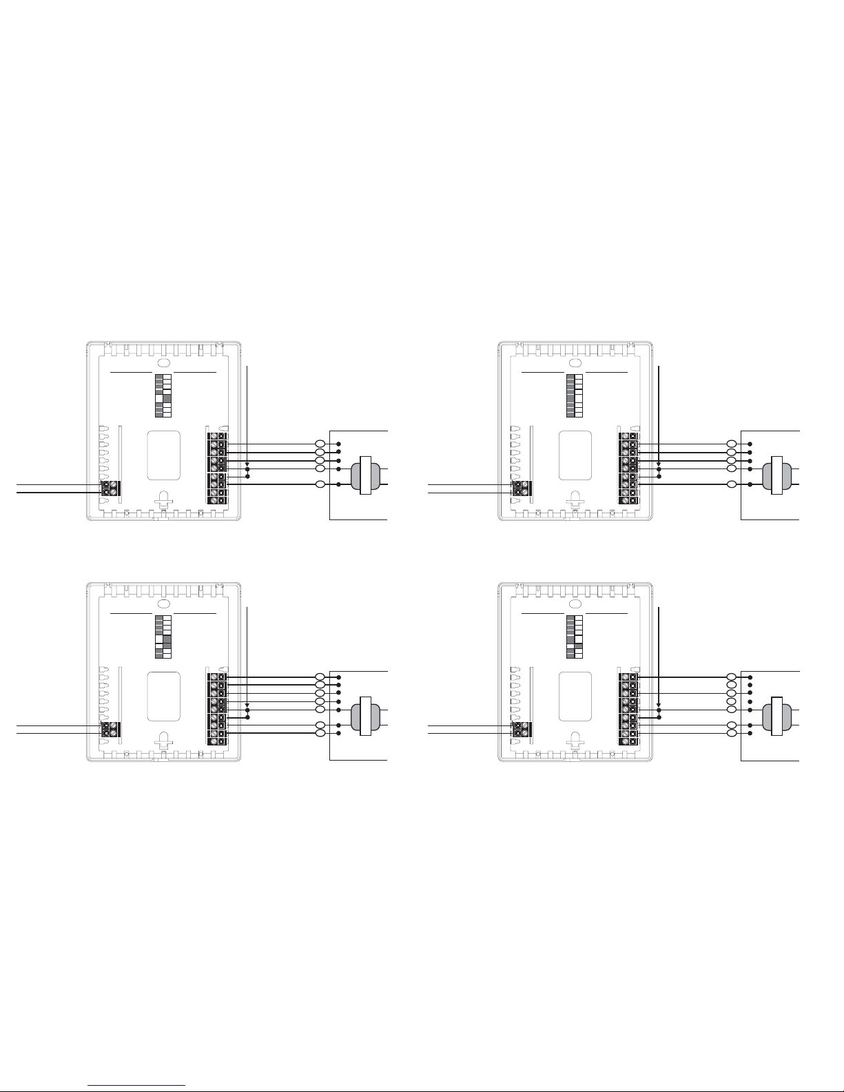
EQUIPMENT WIRING DIAGRAM : RP32-NX
Single-Stage Electric Furnace & Air Conditioning
HVAC CONNECTIONS
Note 1: A Yellow R/24V Jumper is on thermostat
circuit board and must be removed if thermostat
is to be powered over the XBUS network
1
5
3
4
6
2
7
8
COOL
FAN
24 VAC
G
HEAT
W1
Y1
COMMON
Line
Voltage
24 Vac
Transformer
HVAC Equip.
R
C
Y2
W1
Y1
G
R
24V
24V (c)
O/W2
B
(FACTORY DEFAULT) OFF
ON
XBUS
CONNECTIONS
X2
X1
(+) XBUS
RP32-NX
( - ) XBUS
GAS / ELECTRIC
ADAPTIVE RECOVERY ON
4 MINUTES (ON/OFF)
UNLOCKED
DIP1=OFF: ELECTRIC
DIP1=ON: HP NORM
1-STAGE CONTROL
+/- 3F OVERRIDE RANGE
NOT USED (OFF)
HEAT PUMP
ADAPTIVE ROCOVERY OFF
2 MINUTES (ON/OFF)
LOCKED
DIP1=OFF: GAS HEAT
DIP1=ON: HP DUAL FUEL
2-STAGE CONTROL
+/- 5F OVERRIDE RANGE
NOT USED (KEEP OFF)
EQUIPMENT WIRING DIAGRAM : RP32-NX
2-Stage Electric Furnace & Air Conditioning
HVAC CONNECTIONS
Line
Voltage
24 Vac
Transformer
COOL #1
FAN
24 VAC
G
Note 1: A Yellow R/24V Jumper is on thermostat
circuit board and must be removed if thermostat
is to be powered over the XBUS network
HEAT #1
W1
Y1
COMMON
HVAC Equip.
R
C
1
5
3
4
6
2
7
8
W2
Y2
COOL #2
HEAT #2
1
3
4
6
2
7
8
5
Y2
W1
Y1
G
R
24V
24V (c)
O/W2
B
(FACTORY DEFAULT) OFF
ON
XBUS
CONNECTIONS
X2
X1
(+) XBUS
RP32-NX
( - ) XBUS
GAS / ELECTRIC
ADAPTIVE RECOVERY ON
4 MINUTES (ON/OFF)
UNLOCKED
DIP1=OFF: ELECTRIC
DIP1=ON: HP NORM
1-STAGE CONTROL
+/- 3F OVERRIDE RANGE
NOT USED (OFF)
HEAT PUMP
ADAPTIVE ROCOVERY OFF
2 MINUTES (ON/OFF)
LOCKED
DIP1=OFF: GAS HEAT
DIP1=ON: HP DUAL FUEL
2-STAGE CONTROL
+/- 5F OVERRIDE RANGE
NOT USED (KEEP OFF)
EQUIPMENT WIRING DIAGRAM : RP32-NX
2-Stage Gas Furnace & Air Conditioning
HVAC CONNECTIONS
Line
Voltage
24 Vac
Transformer
COOL #1
FAN
24 VAC
G
Note 1: A Yellow R/24V Jumper is on thermostat
circuit board and must be removed if thermostat
is to be powered over the XBUS network
HEAT #1
W1
Y1
COMMON
1
3
4
6
2
7
8
HVAC Equip.
R
C
1
5
3
4
6
2
7
8
W2
Y2
COOL #2
HEAT #2
Y2
W1
Y1
G
R
24V
24V (c)
O/W2
B
(FACTORY DEFAULT) OFF
ON
XBUS
CONNECTIONS
X2
X1
(+) XBUS
RP32-NX
( - ) XBUS
GAS / ELECTRIC
ADAPTIVE RECOVERY ON
4 MINUTES (ON/OFF)
UNLOCKED
DIP1=OFF: ELECTRIC
DIP1=ON: HP NORM
1-STAGE CONTROL
+/- 3F OVERRIDE RANGE
NOT USED (OFF)
HEAT PUMP
ADAPTIVE ROCOVERY OFF
2 MINUTES (ON/OFF)
LOCKED
DIP1=OFF: GAS HEAT
DIP1=ON: HP DUAL FUEL
2-STAGE CONTROL
+/- 5F OVERRIDE RANGE
NOT USED (KEEP OFF)
EQUIPMENT WIRING DIAGRAM : RP32-NX
1-Stage Gas Furnace & Air Conditioning
HVAC CONNECTIONS
Line
Voltage
24 Vac
Transformer
COOL
FAN
24 VAC
G
Note 1: A Yellow R/24V Jumper is on thermostat
circuit board and must be removed if thermostat
is to be powered over the XBUS network
HEAT
W1
Y1
COMMON
1
5
3
4
6
2
7
8
1
3
4
6
2
7
8
HVAC Equip.
R
C
Y2
W1
Y1
G
R
24V
24V (c)
O/W2
B
(FACTORY DEFAULT) OFF
ON
XBUS
CONNECTIONS
X2
X1
(+) XBUS
RP32-NX
( - ) XBUS
GAS / ELECTRIC
ADAPTIVE RECOVERY ON
4 MINUTES (ON/OFF)
UNLOCKED
DIP1=OFF: ELECTRIC
DIP1=ON: HP NORM
1-STAGE CONTROL
+/- 3F OVERRIDE RANGE
NOT USED (OFF)
HEAT PUMP
ADAPTIVE ROCOVERY OFF
2 MINUTES (ON/OFF)
LOCKED
DIP1=OFF: GAS HEAT
DIP1=ON: HP DUAL FUEL
2-STAGE CONTROL
+/- 5F OVERRIDE RANGE
NOT USED (KEEP OFF)
Page 5
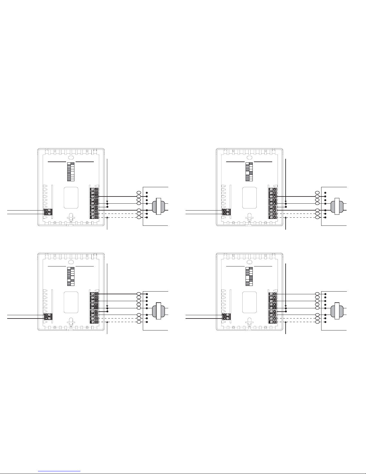
EQUIPMENT WIRING DIAGRAM : RP32-NX
1-Stage Heat Pump, Add-On (Dual Fuel) Operation
HVAC CONNECTIONS
COMPRESSOR #1
FAN
24 VAC
G
O
Note 1: A Yellow R/24V Jumper is on thermostat
circuit board and must be removed if thermostat
is to be powered over the XBUS network
AUXILIARY HEAT
W1
REVERSING VALVE
B
Y1
COMMON
1
5
3
4
6
2
7
8
Line
Voltage
24 Vac
Transformer
HVAC Equip.
R
C
Note 2: Check Heat Pump Installation Instructions
for reversing valve connection, either ‘O’ or ‘B’.
1
5
3
4
6
2
7
8
Y2
W1
Y1
G
R
24V
24V (c)
O/W2
B
(FACTORY DEFAULT) OFF
ON
XBUS
CONNECTIONS
X2
X1
(+) XBUS
RP32-NX
( - ) XBUS
GAS / ELECTRIC
ADAPTIVE RECOVERY ON
4 MINUTES (ON/OFF)
UNLOCKED
DIP1=OFF: ELECTRIC
DIP1=ON: HP NORM
1-STAGE CONTROL
+/- 3F OVERRIDE RANGE
NOT USED (OFF)
HEAT PUMP
ADAPTIVE ROCOVERY OFF
2 MINUTES (ON/OFF)
LOCKED
DIP1=OFF: GAS HEAT
DIP1=ON: HP DUAL FUEL
2-STAGE CONTROL
+/- 5F OVERRIDE RANGE
NOT USED (KEEP OFF)
EQUIPMENT WIRING DIAGRAM :RP32-NX
2-Stage Heat Pump, Add-On (Dual Fuel) Operation
HVAC CONNECTIONS
COMPRESSOR #1
FAN
24 VAC
G
O
Note 1: A Yellow R/24V Jumper is on thermostat
circuit board and must be removed if thermostat
is to be powered over the XBUS network
AUXILIARY HEAT
W1
REVERSING VALVE
B
Y1
COMMON
1
5
3
4
6
2
7
8
Line
Voltage
24 Vac
Transformer
HVAC Equip.
R
C
Note 2: Check Heat Pump Installation Instructions
for reversing valve connection, either ‘O’ or ‘B’.
Y2
COMPRESSOR #2
1
5
3
4
6
2
7
8
Y2
W1
Y1
G
R
24V
24V (c)
O/W2
B
(FACTORY DEFAULT) OFF
ON
XBUS
CONNECTIONS
X2
X1
(+) XBUS
RP32-NX
( - ) XBUS
GAS / ELECTRIC
ADAPTIVE RECOVERY ON
4 MINUTES (ON/OFF)
UNLOCKED
DIP1=OFF: ELECTRIC
DIP1=ON: HP NORM
1-STAGE CONTROL
+/- 3F OVERRIDE RANGE
NOT USED (OFF)
HEAT PUMP
ADAPTIVE ROCOVERY OFF
2 MINUTES (ON/OFF)
LOCKED
DIP1=OFF: GAS HEAT
DIP1=ON: HP DUAL FUEL
2-STAGE CONTROL
+/- 5F OVERRIDE RANGE
NOT USED (KEEP OFF)
EQUIPMENT WIRING DIAGRAM : RP32-NX
1-Stage Heat Pump, Standard Operation
HVAC CONNECTIONS
COMPRESSOR #1
FAN
24 VAC
G
O
Note 1: A Yellow R/24V Jumper is on thermostat
circuit board and must be removed if thermostat
is to be powered over the XBUS network
AUXILIARY HEAT
W1
REVERSING VALVE
B
Y1
COMMON
1
5
3
4
6
2
7
8
Line
Voltage
24 Vac
Transformer
HVAC Equip.
R
C
Note 2: Check Heat Pump Installation Instructions
for reversing valve connection, either ‘O’ or ‘B’.
1
5
3
4
6
2
7
8
Y2
W1
Y1
G
R
24V
24V (c)
O/W2
B
(FACTORY DEFAULT) OFF
ON
XBUS
CONNECTIONS
X2
X1
(+) XBUS
RP32-NX
( - ) XBUS
GAS / ELECTRIC
ADAPTIVE RECOVERY ON
4 MINUTES (ON/OFF)
UNLOCKED
DIP1=OFF: ELECTRIC
DIP1=ON: HP NORM
1-STAGE CONTROL
+/- 3F OVERRIDE RANGE
NOT USED (OFF)
HEAT PUMP
ADAPTIVE ROCOVERY OFF
2 MINUTES (ON/OFF)
LOCKED
DIP1=OFF: GAS HEAT
DIP1=ON: HP DUAL FUEL
2-STAGE CONTROL
+/- 5F OVERRIDE RANGE
NOT USED (KEEP OFF)
EQUIPMENT WIRING DIAGRAM : RP32-NX
2-Stage Heat Pump, Standard Operation
HVAC CONNECTIONS
COMPRESSOR #1
FAN
24 VAC
G
O
Note 1: A Yellow R/24V Jumper is on thermostat
circuit board and must be removed if thermostat
is to be powered over the XBUS network
AUXILIARY HEAT
W1
REVERSING VALVE
B
Y1
COMMON
1
5
3
4
6
2
7
8
Line
Voltage
24 Vac
Transformer
HVAC Equip.
R
C
Note 2: Check Heat Pump Installation Instructions
for reversing valve connection, either ‘O’ or ‘B’.
Y2
COMPRESSOR #2
1
5
3
4
6
2
7
8
Y2
W1
Y1
G
R
24V
24V (c)
O/W2
B
(FACTORY DEFAULT) OFF
ON
XBUS
CONNECTIONS
X2
X1
(+) XBUS
RP32-NX
( - ) XBUS
GAS / ELECTRIC
ADAPTIVE RECOVERY ON
4 MINUTES (ON/OFF)
UNLOCKED
DIP1=OFF: ELECTRIC
DIP1=ON: HP NORM
1-STAGE CONTROL
+/- 3F OVERRIDE RANGE
NOT USED (OFF)
HEAT PUMP
ADAPTIVE ROCOVERY OFF
2 MINUTES (ON/OFF)
LOCKED
DIP1=OFF: GAS HEAT
DIP1=ON: HP DUAL FUEL
2-STAGE CONTROL
+/- 5F OVERRIDE RANGE
NOT USED (KEEP OFF)
18 19 2017
Page 6
22 23 2421
352-00001-02 Rev B
SPECIFICATIONS
Rated Voltage . . . . . . . . . . . . . . . . 20-30 VAC, 24 nominal
Rated A.C. Current . . . . . . . . . . . . 0.050 Amps to 0.75 Amps
continuous per output with
surges to 3 Amps Max.
Rated D.C. Current . . . . . . . . . . . . 0 Amps to 0.75 Amps
continuous per output with
surges to 3 Amps Max.
Control Range . . . . . . . . . . . . . . . . Heating:
38° to 88°F in 1° Steps
(5° to 30°C in 1° Steps)
Cooling:
60° to 108°F in 1° Steps
(16° to 40°C in 1° Steps)
Thermostat Measurement Range . . 28° to 124°F (0° to 48°C)
O.D.T. Displayed Range . . . . . . . . -50° to 124°F (-48° to 48°C)
Control Accuracy . . . . . . . . . . . . . . ± 1°F at 68°F Accuracy
(± .5°C at 20°C Accuracy)
Minimum Deadband . . . . . . . . . . . (between heating and cooling)
2°F (1°C)
NOTE: This thermostat contains electronic circuitry replacing the
conventional mechanical anticipator.
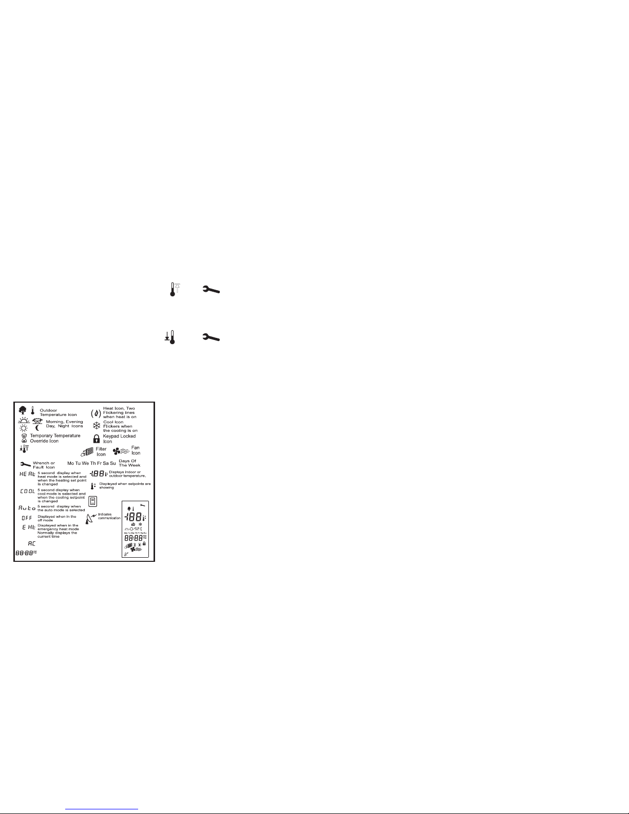
DESCRIPTION OF ICONS
SENSOR FAULTS
There are two sensor faults:
1. Internal sensor is shorted.
2. Internal sensor is open.
When the internal sensor is shorted [the sensed temperature
>= 124°F (48°C)], all equipment is turned off and the following
icons are ashed on the LCD:
When the internal sensor is open [the sensed temperature
<= 32°F (0°C)], all equipment is turned off and the following icons
are ashed on the LCD:
An open condition is ignored the rst 20 minutes after powering
the thermostat to allow the equipment to heat the surrounding
environment. This will avoid premature deactivation of the
equipment if the ambient temperature should happen to be
below 32°F (0°C).
1 (ONE) YEAR LIMITED WARRANTY
NetworkThermostat™ warrants to the original purchaser that
this product and its component parts will be free from defects in
workmanship and materials for a period of one year from the date
of purchase with proof of purchase.
Warranty Limitations
This warranty begins on the date of purchase.
Warranty is Void if:
The date code is defaced or removed.
The product has a defect or damage due to product alteration,
connection to an improper electrical supply, shipping and
handling, accident, re, ood, lightning, or other conditions
beyond the control of the manufacturer.
The product is not installed according to the manufacturers
instructions and specications.
The product has been installed near sources of electromagnetic
interference (EMI) such as arcing relay contacts.
Owner’s Responsibility
Provide proof of purchase.
Provide normal care and maintenance.
Pay for freight, labor and travel.
Pay for service calls related to product installation.
Return any defective product.
In no event shall the manufacturer be liable for incidental or
consequential damages.
This warranty gives you specic legal rights and you may have
others which vary by state and/or province. For example, some
states and/or provinces do not allow the exclusion or limitation of
incidental or consequential damages, so this exclusion may not
apply to you.
The manufacturer’s continuing commitment to quality products
may require a change in specications without notice.
Net/X™ RP32-NX Programmable Thermostat meets CA Title
24 requirements.
This equipment, if installed in strict accordance with the
manufacturer’s instructions, complies with the limits for a Class B
computing device pursuant to Subpart J of Part 15 of FCC rules.
Displays clock and vacation
times in program mode
30 minute display
during power failure
High and Low
Sensor Values
(Indicating Faults)
Adaptive
Recovery
Flashes
when active
Location Of
Icons On LCD
 Loading...