

Network Technologies Incorporated ENVIROMUX-SDS-CELC, ENVIROMUX-SDS-CELCP Installation Instruction
Page 1
Tel:330-562-7070
N
Fax:330-562-1999
NTI
NETWORK
R
TECHNOLOGIES
INCORPORATED
1275 Danner Dr
Aurora, OH 44202
www.networktechinc.com
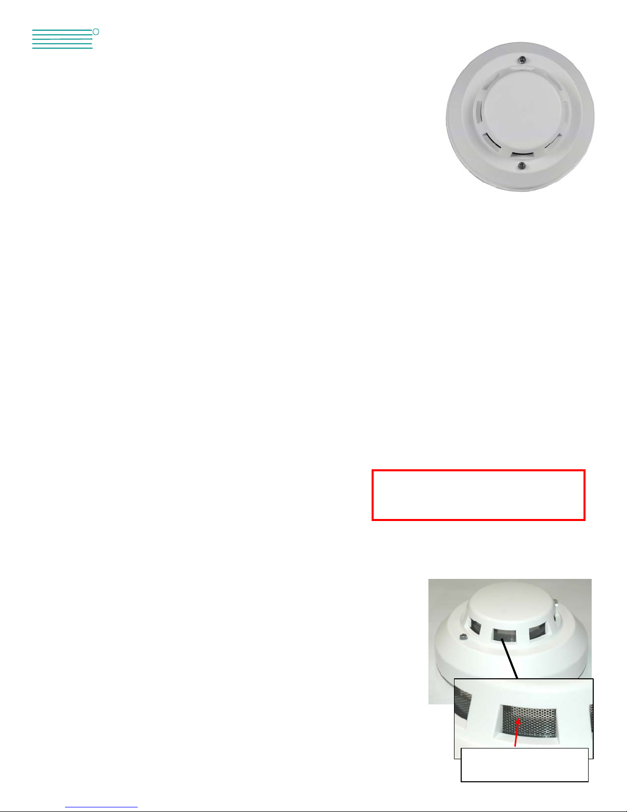
ENVIROMUX-SDS-CELC(P)
PHOTOELECTRIC SMOKE
DETECTION SENSOR
Installation Instruction
Introduction
The ENVIROMUX-SDS-CELC(P) is a smoke detection sensor intended for connection to an NTI ENVIROMUX-MICRO-T(RHP),
ENVIROMUX-16D/5D/2D, or ENVIROMUX-MINI-LXO (ENVIROMUX). When properly connected, the ENVIROMUX-SDS-CELC(P)
will provide signals to the ENVIROMUX that with proper configuration will result in alert messages being sent to users of the
ENVIROMUX. The ENVIROMUX-SDS-CELC(P) has screw terminals for easy user connections and the ENVIROMUX-SDS-CELCP
includes a 12VDC AC adapter.
This Photoelectric smoke detector (hereinafter called Detector) detects smoke using a couple of infrared diodes. The principle of
detecting is based on the fact that a granule of smoke can reflect infrared light. Infrared diodes are placed in a special chamber. The
chamber can shield external light, but doesn't prevent smoke from entering it. In the absence of smoke, the diodes can detect very
weak infrared light. As smoke enters the chamber, the diodes will receive more and more light. When the smoke reaches a certain
density, the Detector will sound out an alarm signal. In order to reduce interference and l ower power consumption, the emitting circuit
uses a pulse signal. The Detector has a special structural design and ASIC, providing a dustproof, mothproof and anti-outside light
interference feature. The Detector is suitable for detecting the smoke in a house, shop, hotel, restaurant, office building, school, bank,
library, etc.
Product Features
The detector works once connected directly to DC power. A flashing LED indicates the Detector is working normally and an LED that
stays ON solid indicates an alarm condition. Normally-closed output contacts will open in an alarm conditio n. Connections to these
contacts are made when the Detector is secured to the mounting base.
• Infrared Photoelectric Smoke Detector
• LED alarm indicators
• Selectable Alarm Output N/C or N/O Relay (Default is N/C)
• Selectable Latching Feature (Default is latch ON)
• Open Contact/LED Indicating Alarm
• Anti-light, Mothproof, Dustproof
• Stainless steel shield, Anti-RFI (20V/m-1GHz)
Preparation for Installation
1. There should be no large objects that would block airflow within 0.5m (20 inches) of
the Detector.
2. There must be no source of wind flow within 1.5m (60 inches) of the Detector.
3. The Detector should be mounted more than 0.5m (20 inches) from any wall.
4. The distance between two Detectors can be no less than 15m (50 feet) and the
distance between Detector and corner must he less than half of the distance between
Detectors.
5. Always install the Detector on a horizontal surface. If it must be installed on a
slanted surface, the angle of slant must be less than 45 degrees.
6. Clean the Detector by brushing the openings in the h ead with a soft brush every six months
to ensure the sensitivity and life of the product. Be sure to power OFF the Detector before
cleaning.
ote: The ENVIROMUX-SDS-CELC(P) is
NOT intended to be used as a primary
fire and smoke detection device.
Clean every six months
with a soft brush
1
Page 2
T
Switch Contact Connection
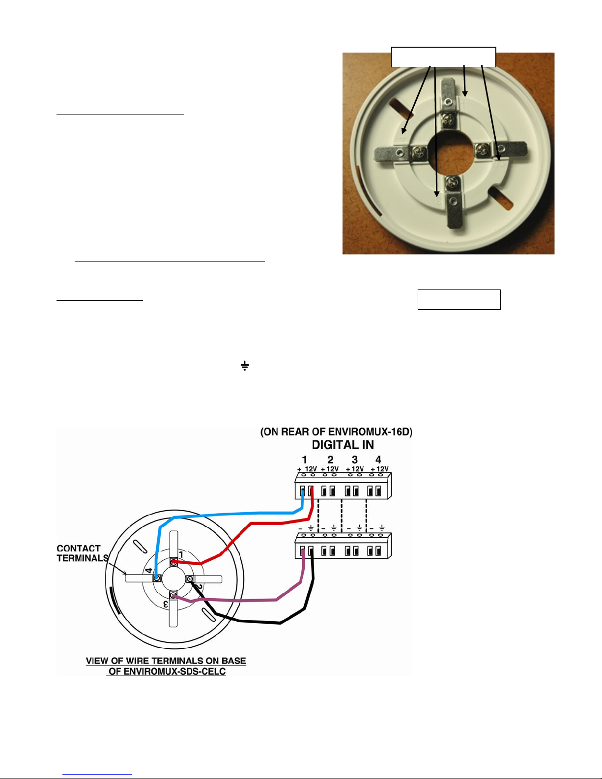
1. Connect two 18-22 awg wires (not supplied) to “Digital In”
terminals “+” and “---”on the ENVIROMUX-16D (sets 1-8) ,
“Digital In” terminals on the ENVIROMUX-MINI-LXO,
ENVIROMUX-MICRO-T(RHP)(set 1 or 2), ENVIROMUX-2D and
ENVIROMUX-5D (sets 1-5) or any set of dry contacts on the
ENVIROMUX-MINI (set 1, 2, 3 or 4). (All shown in the images
below)
2. Connect the other end of those two wires to the smoke detection
sensor base at terminals “3” and “4”.
For more Digital In connections in conjunction with the ENVIROMUX16D/5D/2D, add an ENVIROMUX-DI16DO16(R) Digital Input/Output
Expander.
See http://www.networktechinc.com/io-expander.html
Power Connection
For Model ENVIROMUX-SDS-CELC:
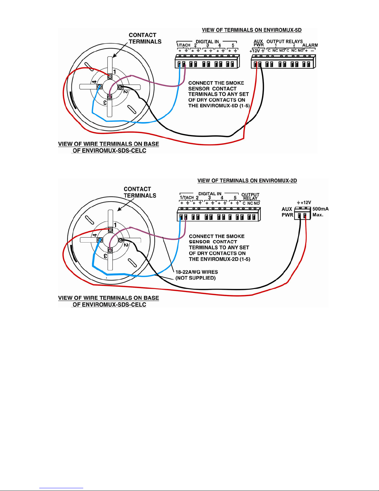
1. Connect two 18-22awg wires (not supplied) between the ENVIROMUX-16D and the ENVIROMUX-SDS-CELC as shown below.
(Wiring for ENVIROMUX-2D and ENVIROMUX-5D also shown.)
a. Connect one wire between “12V” on the SYSTEM and terminal “1” on the smoke detector.
b. Connect the other wire between “ “ (ground) on the SYSTEM and terminal “2” on the smoke detector.
2. Be sure to tighten terminals to secure each conductor.
erminal numbers
for more details.
Detector Base
2
Page 3
For Model ENVIROMUX-SDS-CELCP:
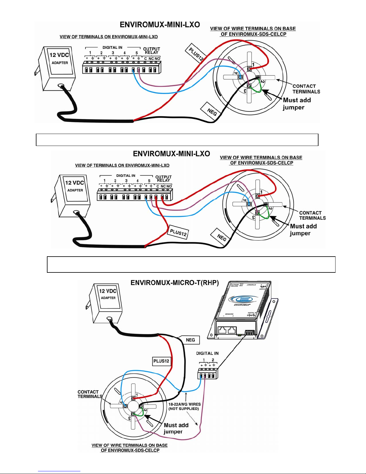
When a 12VDC power supply is not available on the SYSTEM (for example, ENVIROMUX-MICRO-T(RHP) and ENVIROMUX-MINILXO do not include terminals to provide 12VDC power to sensors), model ENVIROMUX-SDS-CELCP can be used.
1. Connect the AC adapter wire labeled “PLUS 12” to terminal “1” on the smoke detection sensor.
2. Connect the AC adapter wire labeled “NEG” to terminal “2” on the smoke detection sensor.
3. Add a jumper wire between terminals “2” and “3” on the smoke detector.
4. Be sure to tighten terminals to secure each conductor.
3
Page 4
g
Wired using this method the smoke detector must be manually power-cycled in order to reset it when it goes into alert.
Wired using this method the smoke detector can be power-cycled through the web interface when it is in ale rt. Make sure
that no sensors are confi
ured to activate the output relay when in or out of alert. (See page 7)
4
Page 5
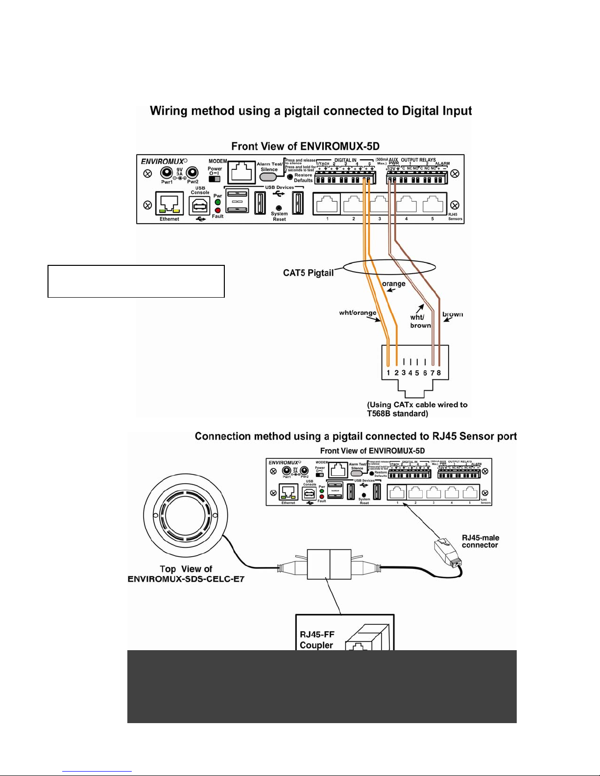
For Model ENVIROMUX-SDS-CELC-E7:
The ENVIROMUX-SDS-CELC-E7 includes a 7 foot pre-wired cable with RJ45 connector (wiring shown below) for plug in to either an
available RJ45 Sensor port in an ENVIROMUX-2D/5D/16D or into a pigtail wired to a Digital Input on an ENVIROMUX-2D/5D/16D.
No additional power supply is required. The 7 foot cable can be extended to up to 1000 feet using a CAT5 patch cable (minimum
24AWG) using the supplied RJ45 coupler.
The ENVIROMUX-SDS-CELC(-E7)
draws 15mA @ 12VDC
5
Page 6
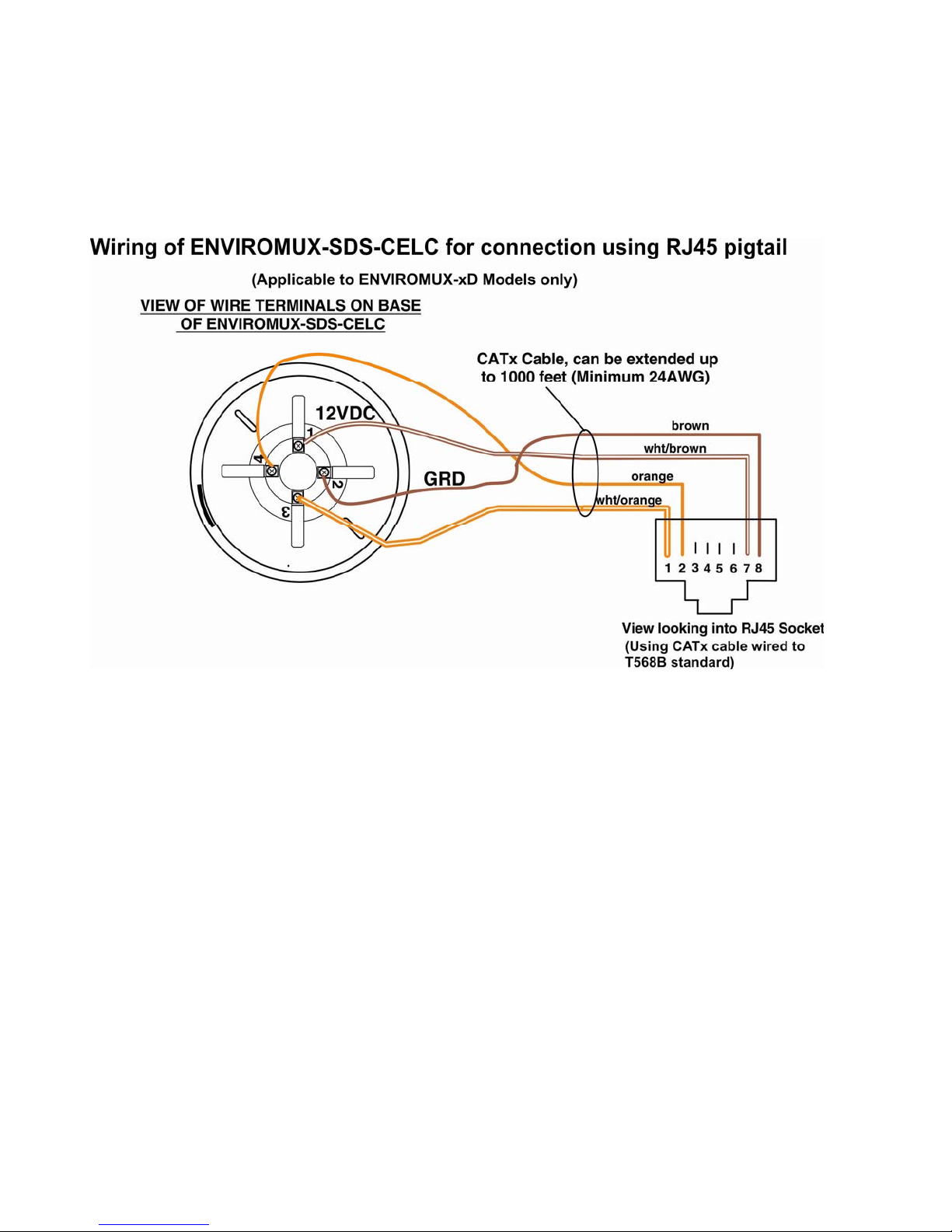
To wire your own CATx patch cable to an ENVIROMUX-SDS-CELC sensor, follow the wiring instruction below.
6
Page 7
T
p
Selectable Features
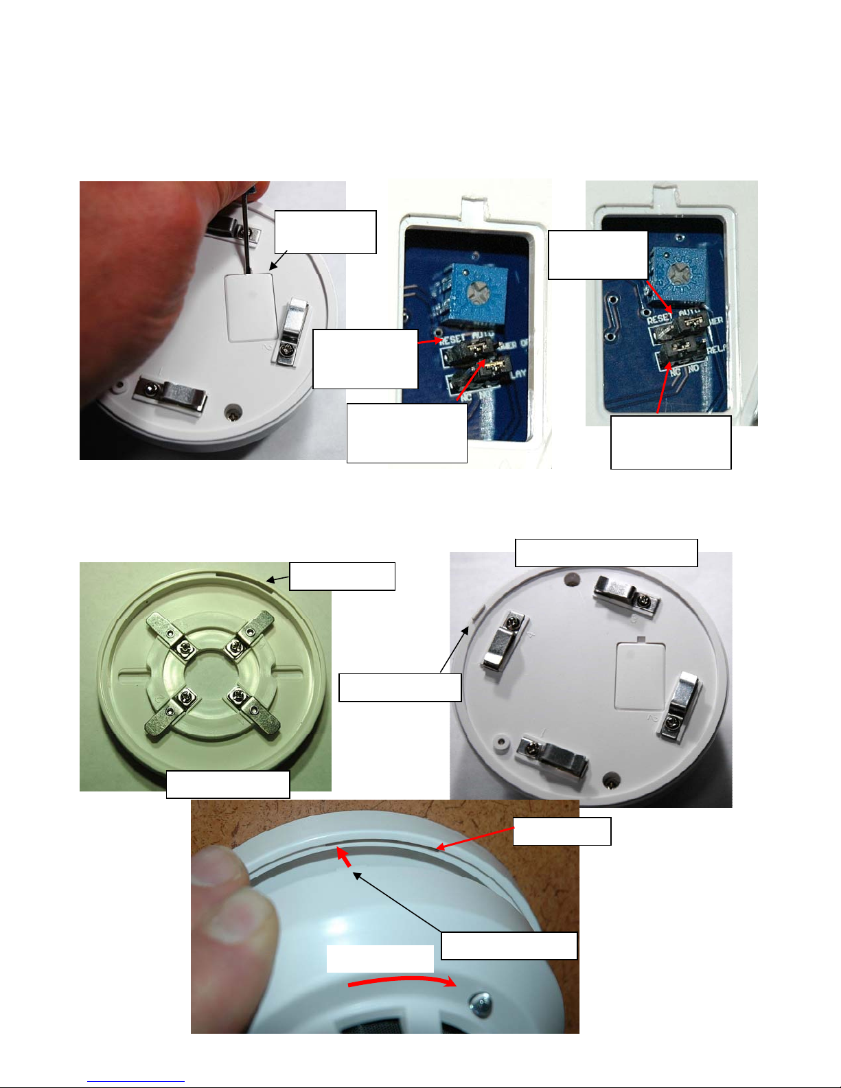
You can select whether the alarm output relay is in a normally-closed (the default) or normally-open position, and w hether the audible
alarm should latch ON until the unit is power-cycled (default setting) OR auto-reset and return to OFF when the alarm condition clears.
To change this setting, remove the configuration cover with a very small flat-blade screwdriver or similar tool. Using tweezers, place
the jumpers in the desired position.
Note: The ENVIROMUX-SDS-CELC(P) is NOT intended to be used as a primary fire and smoke detection device.
Install Detector to Base
Connect the Detector to the base. Line the tab on the Detector up with the left end of the slot in the base. Press the Detector into the
slot so that the detector is evenly resting on the base all the way around. Then rotate the Detector clockwise approximately 1”
(2.54cm) to lock in the detector and engage the contacts on the base
Top view of Base
configuration
cover
Top Jumper
in “latch ON”
position
Slot in Base
Tab on Detector
Rotate to lock
Output Relay
set to NormallyOpen
Top Jumper in
“auto-reset”
osition
Output Relay
set to NormallyClosed
.
Bottom View of Detector
Slot in Base
ab on Detector
7
Page 8
Operation
1. Power up the ENVIROMUX (if not already powered ON), or, when used, connect the AC adapter to an appropriate power source.
The LEDs on the Detector will flash red to indicate the sensor is functioning and in status-ready conditio n. The LEDs will illuminate
solid red when smoke is detected.
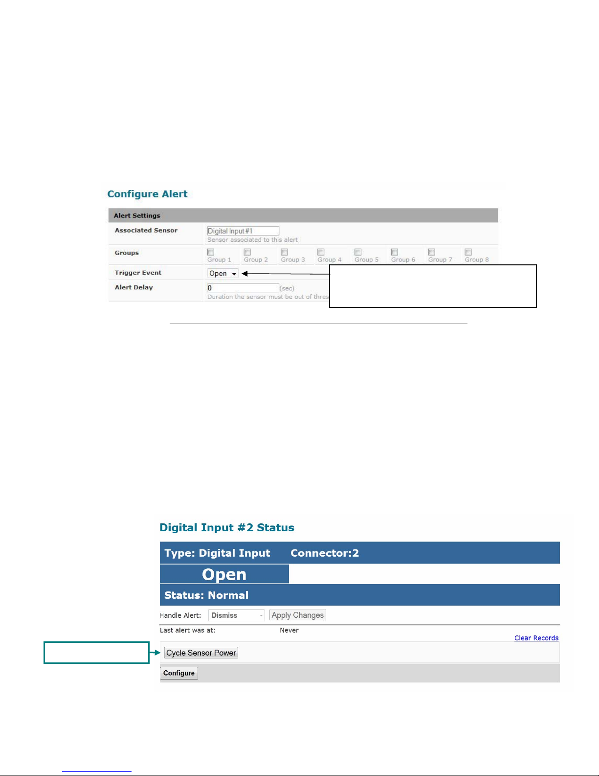
2. Configure the ENVIROMUX to report signals from the connected dry contact sensor as smoke detection sensor alerts. (Refer to
the ENVIROMUX manual for details on configuration- see also example below and on the following pages.) When smoke is
detected, the switch terminals on the ENVIROMUX-SDS-CELC(P) will close to cause an alert message to be sent from the
ENVIROMUX.
Use “Open” if the Detector is configured with
the output relay set to normally-closed (the
default)
Example of sensor configuration in ENVIROMUX-MICRO-T(RHP)
Cycle Sensor Power on ENVIROMUX-xD Models
When the smoke detection sensor senses smoke and an alert condition is triggered, in order to reset the smoke detector to a ready state after the
presence of smoke has been resolved, the smoke detector must be power-cycled.
A “Cycle Sensor Power” button (below) is provided for each sensor connected to the “Digital In” terminals on the
ENVIROMUX-16D (locally-powered-by Digital Inputs only). To momentarily disrupt power to any sensor powered-by a Digital Input terminal, click on
this button. The 12VDC power will be disrupted to the sensor for 5 seconds and then automatically restored.
Note: On ENVIROMUX-5D and -2D, the “Cycle Sensor Power” will cause the “AUX PWR” terminals to cycle power. This
will only be effective for the smoke detection sensor if the sensor is being powered from these terminals. If your sensor is
powered, for example, from an AC adapter, the “Cycle Sensor Power” button will have no effect on that sensor, but it will still
cycle power on the “AUX PWR” terminals, disrupting any device getting power from these terminals for 5 seconds. Keep
this in mind if more than one sensor (or device) is being powered from these terminals.
Cycle Sensor Power
Application Note:
A smoke detector connected to an RJ45 Sensor Port does not have “Cycle Sensor Power” button and must be manually disconnected
(unplugged) and reconnected in order to reset it. To use this feature, make sure the smoke detector is wired to a Digital Input.
8
Page 9
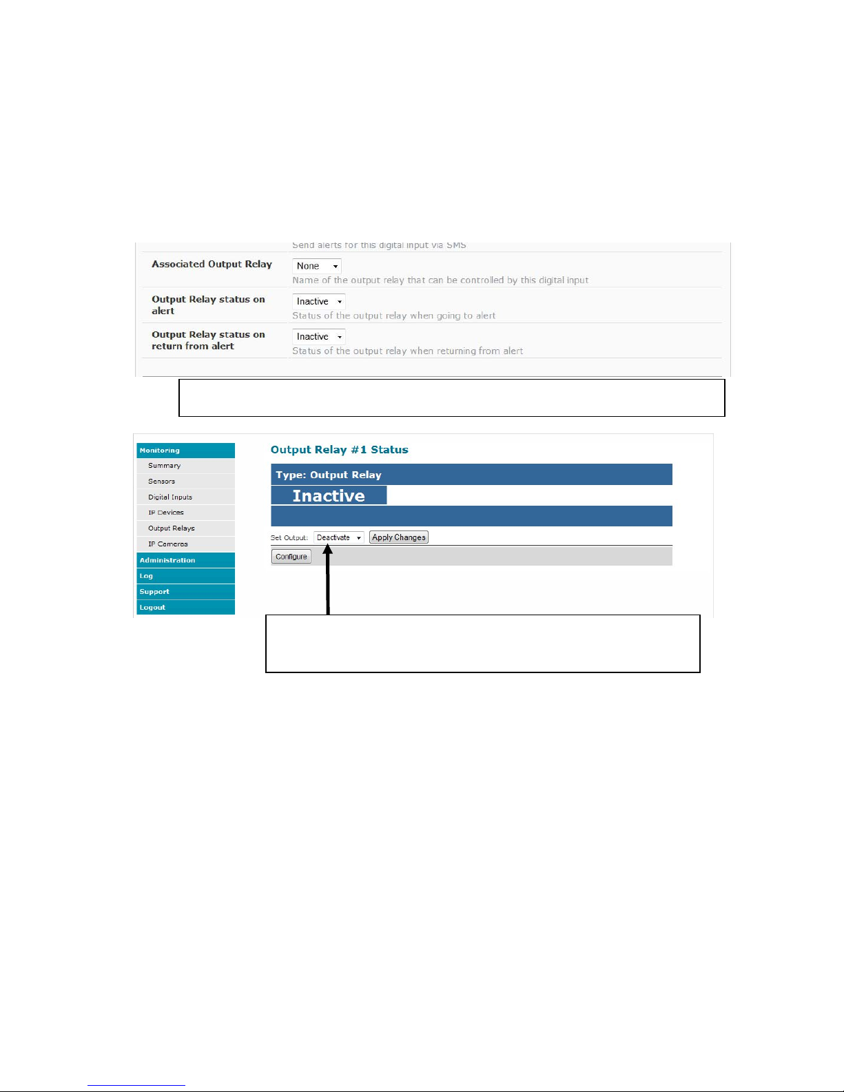
Cycle Sensor Power on ENVIROMUX-MINI-LXO
The power to the smoke detector can also be power-cycled on the ENVIROMUX-MINI-LXO when wired as shown on the lower image on page 4. If
the output relay is used to control power to the smoke detector, the output relay can be manually activated (to open power to the smoke detector) and
then deactivated (to restore power to the smoke detector.
When wired in this fashion, make sure that none of the sensors are configured to have the output relay status change to “Active”. Both fields (below)
must be set to “Inactive”. Otherwise, when the relay is active the smoke detector will be powered OFF.
Make sure the ENVIROMUX Output Relay status for both fields in all sensor configurations is set to
“Inactive” if the output relay is used to power the smoke detector.
To power-cycle the smoke detector using the web interface, set the output to
“Activate”, click “Apply Changes”, then set to “Deactivate” and click “Apply
Changes” again.
9
Page 10
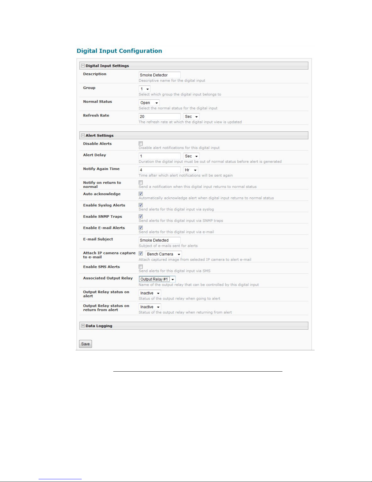
Example of sensor configuration in ENVIROMUX-MINI-LXO
10
Page 11
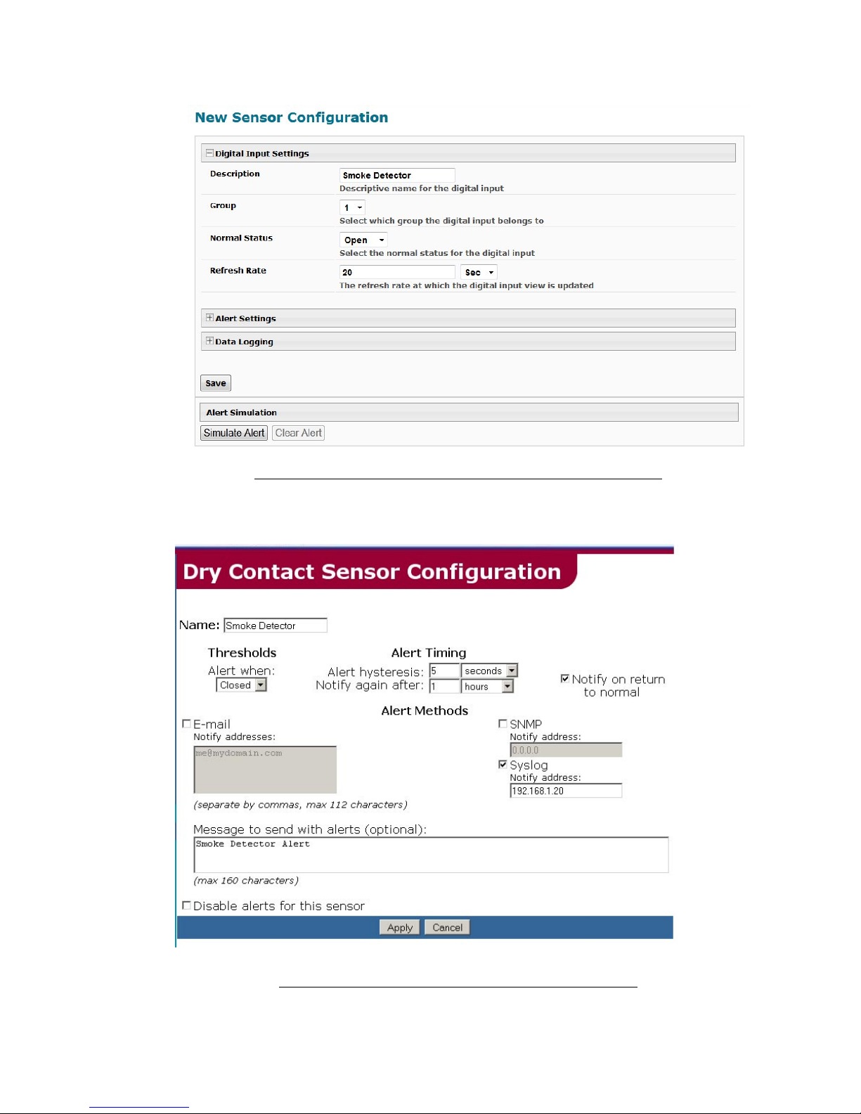
Example of sensor configuration in ENVIROMUX-16D/-5D/-2D
Example of sensor configuration in ENVIROMUX-MINI
11
Page 12

Specifications
Operating Voltage: 9-15VDC
Operating current: Standby 8mA (N/O) 15mA(N/C)
Alarm 15mA(N/O) 8mA (N/C)
Relay Contact Rating: 100mA @ 28VDC
Alarm Output: Relay Output
Alarm Indicator: LEDs (Red)
Sensitivity: 0.5dB/m ±0.1dB/m
Temperature Range: -10º to 50ºC
Humidity: 0% to 95% R.H. (non-condensing)
Dimensions: 103 X 53mm (4.0 X 2.1 in.)
Standard: RoHS
Warranty Information
The warranty period on this product (parts and labor) is two (2) years from the date of purchase. Please contact Network
Technologies Inc at (800) 742-8324 (800-RGB-TECH) or (330) 562-7070 or visit our website at http://www.networktechinc.com
information regarding repairs and/or returns. A return authorization number is required for all repairs/returns.
COPYRIGHT
Copyright © 2007, 2016 by Network Technologies Inc. All rights reserved. No part of this publication may be reproduced, stored in a
retrieval system, or transmitted, in any form or by any means, electronic, mechanical, photocopying, recording, or otherwise, without
the prior written consent of Network Technologies Inc, 1275 Danner Drive, Aurora, Ohio 44202.
CHANGES
The material in this guide is for information only and is subject to change without notice. Network Technologies Inc reserves the right
to make changes in the product design without reservation and without notification to its users.
for
Man241 Rev 5/17/16
12
 Loading...