

Network Technologies Incorporated ENVIROMUX-MICRO-TRHP, ENVIROMUX-MICRO-T Installation Manual
Page 1
ENVIROMUX
®
Series
ENVIROMUX-MICRO-T(RHP)
Micro Environment Monitoring System
Installation and Operation Manual
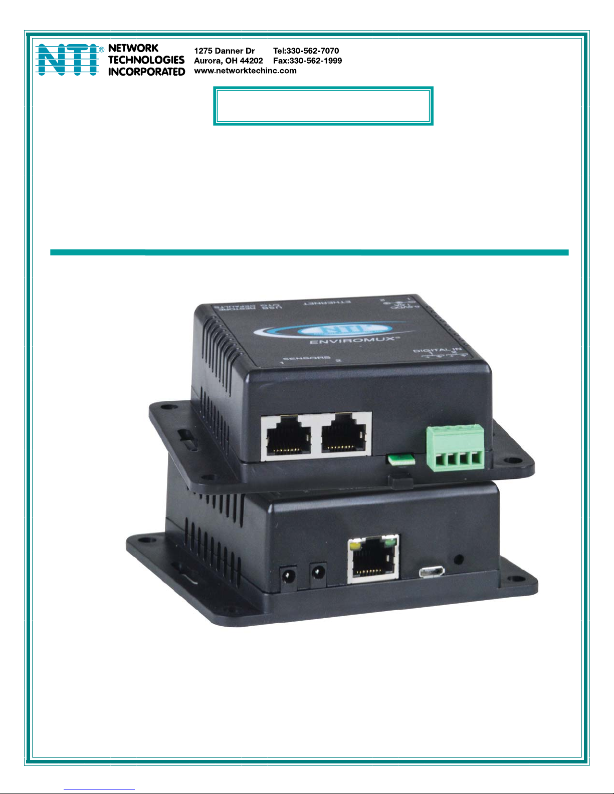
Front View of ENVIROMUX-MICRO-TRHP
MAN220 Rev Date 6/1/16
Page 2

TRADEMARK
ENVIROMUX is a registered trademark of Network Technologies Inc in the U.S. and other countries.
COPYRIGHT
Copyright © 2009, 2016 by Network Technologies Inc. All rights reserved. No part of this publication may be reproduced, stored
in a retrieval system, or transmitted, in any form or by any means, electronic, mechanical, photocopying, recording, or otherwise,
without the prior written consent of Network Technologies Inc, 1275 Danner Drive, Aurora, Ohio 44202.
CHANGES
The material in this guide is for information only and is subject to change without notice. Network Technologies Inc reserves the
right to make changes in the product design without reservation and without notification to its users.
FIRMWARE VERSION
Current firmware version 2.00
i
Page 3

TABLE OF CONTENTS
Introduction......................................................................................................................................................................1
Supported Web Browsers ...............................................................................................................................................2
Materials..........................................................................................................................................................................2
Connectors and LEDs.....................................................................................................................................................3
Installation .......................................................................................................................................................................4
Mounting......................................................................................................................................................................4
Connect Sensors.........................................................................................................................................................4
Ethernet Connection....................................................................................................................................................7
Connect the Power......................................................................................................................................................8
Cable Restraint.........................................................................................................................................................8
Connect a Modem .......................................................................................................................................................9
Overview........................................................................................................................................................................10
Administration.........................................................................................................................................................10
General Functions...................................................................................................................................................10
Security...................................................................................................................................................................11
Device Discovery Tool...................................................................................................................................................12
How to Use the Device Discovery Tool.....................................................................................................................12
Operation via Web Interface..........................................................................................................................................13
Log In and Enter Password .......................................................................................................................................13
Summary....................................................................................................................................................................15
Sensor Settings.......................................................................................................................................................17
Alerts..........................................................................................................................................................................17
Configure Alerts......................................................................................................................................................18
Smart Alert.................................................................................................................................................................20
Administration............................................................................................................................................................24
System Settings......................................................................................................................................................24
Network Configuration............................................................................................................................................25
SNMP Settings........................................................................................................................................................26
Email Server Settings .............................................................................................................................................27
Time Settings..........................................................................................................................................................28
Set Local Time........................................................................................................................................................28
Users.......................................................................................................................................................................29
IP Cameras.............................................................................................................................................................31
Update Firmware ....................................................................................................................................................32
Log.............................................................................................................................................................................33
View Event Log.......................................................................................................................................................33
View Data Log.........................................................................................................................................................34
IP Devices..................................................................................................................................................................36
Support ......................................................................................................................................................................37
Logout........................................................................................................................................................................37
Operation via Text Menu- ENVIROMUX.......................................................................................................................38
Connect to ENVIROMUX from Terminal through Ethernet.......................................................................................38
Connect to ENVIROMUX from Command Line.........................................................................................................39
ii
Page 4

Using the Text Menu..................................................................................................................................................40
Monitoring...............................................................................................................................................................40
Display Network Settings........................................................................................................................................43
Restore Defaults Button................................................................................................................................................44
USB Port........................................................................................................................................................................44
How To Setup Email......................................................................................................................................................45
Technical Specifications................................................................................................................................................50
Troubleshooting.............................................................................................................................................................51
Index..............................................................................................................................................................................52
Warranty Information.....................................................................................................................................................52
TABLE OF FIGURES
Figure 1- Mount with sensor towards the floor...................................................................................................................................4
Figure 2- Connect Sensors................................................................................................................................................................5
Figure 3- Terminal block for dry-contact sensors...............................................................................................................................5
Figure 4- Secure liquid detection sensor with tape............................................................................................................................6
Figure 5- Portion of Water Sensor configuration page.......................................................................................................................6
Figure 6- Connect ENVIROMUX-MICRO to the Ethernet..................................................................................................................7
Figure 7- Connect the AC adapter and power-up..............................................................................................................................8
Figure 8- Use cable restraint..............................................................................................................................................................8
Figure 9- Connect a Modem ..............................................................................................................................................................9
Figure 10- Device Discovery Tool....................................................................................................................................................12
Figure 11- Login prompt to access web interface............................................................................................................................13
Figure 12- Summary page...............................................................................................................................................................14
Figure 13- Summary page...............................................................................................................................................................15
Figure 14- List of alerts configured ..................................................................................................................................................16
Figure 15- Sensor settings...............................................................................................................................................................17
Figure 16- List of configured alerts and their status.........................................................................................................................17
Figure 17- Select a sensor to add an alert configuration for ............................................................................................................18
Figure 18- Alert Configuration page for Temperature/Humidity sensors..........................................................................................18
Figure 19- Alert configuration for Digital sensor- minor difference...................................................................................................19
Figure 20- Smart Alerts page...........................................................................................................................................................20
Figure 21- Sensor to be used for a predefined event.......................................................................................................................20
Figure 22- Event Logical Function Diagram.....................................................................................................................................22
Figure 23- Examples of Smart Alert conditions................................................................................................................................23
Figure 24- System Settings page.....................................................................................................................................................24
Figure 25- Network Settings page ...................................................................................................................................................25
Figure 26- SNMP Settings...............................................................................................................................................................26
Figure 27- Time and Date Settings..................................................................................................................................................28
Figure 28- Users List........................................................................................................................................................................29
Figure 29- User2 added- ready to configure....................................................................................................................................29
Figure 30- User Settings..................................................................................................................................................................29
Figure 31- IP Camera Monitoring.....................................................................................................................................................31
Figure 32- Configure IP Cameras....................................................................................................................................................31
Figure 33- Update Firmware page...................................................................................................................................................32
Figure 34- Event Log page ..............................................................................................................................................................33
Figure 35- Data Log page................................................................................................................................................................34
Figure 36- IP Devices listing-none monitored yet ............................................................................................................................36
iii
Page 5

Figure 37- IP Device Configuration page.........................................................................................................................................36
Figure 38- IP Device list with new devices added............................................................................................................................37
Figure 39- Support...........................................................................................................................................................................37
Figure 40- Logout ............................................................................................................................................................................37
Figure 41- Terminal connection through Ethernet port ....................................................................................................................38
Figure 42- Text Menu Login screen.................................................................................................................................................38
Figure 43- Text Menu- Administrator Main Menu.............................................................................................................................39
Figure 44- Text Menu-Monitoring Menu...........................................................................................................................................40
Figure 45- Text Menu-Sensor Status...............................................................................................................................................41
Figure 46- Text Menu- Digital Input Status ......................................................................................................................................41
Figure 47- Text Menu-View IP Devices............................................................................................................................................42
Figure 48- Text Menu-Configure Sensors list ..................................................................................................................................42
Figure 49- Text Menu-Network Settings ..........................................................................................................................................43
Figure 50- Location of Restore Defaults button ...............................................................................................................................44
Figure 51- USB OTG port................................................................................................................................................................44
Figure 52- Email Server Settings example.......................................................................................................................................45
Figure 53- Configure user to receive alerts via email.......................................................................................................................46
iv
Page 6
NTI Micro Environment Monitoring System
INTRODUCTION
The ENVIROMUX® Micro Environment Monitoring System (ENVIROMUX) monitors (from a remote location) critical
environmental conditions, such as temperature, humidity, liquid water presence, power, intrusion, and smoke. When a sensor
goes out of range of a configurable threshold, the system will notify you via email, web page, network manageme nt (SNMP),
and/or SMS messages (via external USB 3G modem). For a complete list of sensors supported, visit our website at
http://www.networktechinc.com/environment-monitor-micro.html
The system functions independently or as an IP-connected remote sensor for the ENVIROMUX-2D/5D/16D.
The ENVIROMUX-MICRO-T features a built-in temperature sensor, two RJ45 sensor ports for external temperature/humidity
sensors, and two dry contact inputs.
The ENVIROMUX-MICRO-TRHP features a built-in temperature/humidity sensor, two RJ45 sensor ports for external
temperature/humidity sensors, two dry contact inputs for the connection of contact-closure sensors and built-in Power over
Ethernet (PoE).
Features and Applications
¾ Monitor and manage server room environmental conditions over IP.
¾ Monitors and operates at temperatures from -4°F to 185°F (-20ºC and 85ºC) and 0% to 90% non-condensing relative
humidity.
¾ Includes one integrated temperature sensor
¾ Sensors supported:
• 2 temperature sensors
• 2 digital input devices (dry contact or water detection sensors)
¾ Operates and configures via HTTP web page.
¾ Six remote users can access the system simultaneously.
¾ Supports SMS alert messages via GSM modem
¾ Supports SMTP protocol
¾ Supports SNMP V1, and V2C protocols
¾ Supports SNTP protocol
¾ Supports Microsoft Internet Explorer 6.0 and higher, Firefox 2.0 and higher, Chrome, Safari 4.0 or higher, and Opera 9.0
or higher
¾ Sensor alerts and log messages are sent using email, Syslog, and SNMP traps when any monitored environmental
condition goes out of the user-specified range.
¾ Sensor alert and end of alerts are posted in message log, which is accessible through web interface.
¾ SNMP trap messages can be imported into Microsoft Excel
¾ Use in data centers, co-lo sites, web hosting facilities, telecom switching sites, POP sites, server closets, or any
unmanned area that needs to be monitored.
¾ Security: HTTPS, SSLv3, AES 256-bit encryption, 3DES, Blowfish, RSA, EDH-RSA, Arcfour, SNMP(v1,v2c), 16-
character username/password authentication, user account restricted access rights.
¾ Monitor (ping) up to 4 IP network devices.
o Configure the timeout and number of retries to classify a device as unresponsive.
o Alerts are sent if devices are not responding.
¾ Monitored sensors and devic es can be individually named (up to 63 characters).
¾ Monitor environmental conditions.
o Supports two temperature/humidity sensors and up to 2 dry contacts or water detection sensors.
o When a sensor goes out of range of a configurable threshold, the system will notify you via email, syslog, web
page, and network management (SNMP).
¾ Firmware upgradeable "in-field" using web interface.
Options:
¾ The ENVIROMUX-TRHP includes an additional integrated humidity sensor and built-in Power over Ethernet (PoE)
(supports IEEE 802.3af and 802.3at standards.)
.
1
Page 7

NTI Micro Environment Monitoring System
SUPPORTED WEB BROWSERS
Most modern web browsers should be supported. The following browsers have been tested:
• Microsoft Internet Explorer 6.0 or higher
• Mozilla FireFox 2.0 or higher
• Opera 9.0 or higher
• Google Chrome 9.0.5 or higher
• Safari 4.0 or higher for MAC and PC
MATERIALS
Materials supplied with this kit:
• NTI ENVIROMUX-MICRO-T/TRHP Micro Environment Monitoring System
• 1- 120VAC or 240VAC at 50 or 60Hz-5.5VDC/1.5A AC Adapter (ENVIROMUX-MICRO-T only)
• 1- CB7103 USB2-AFMBM-6IN 6 inch USB 2.0 female type A-to-micro male cable
• CD containing a pdf of this manual, a SNMP MIB file, and the NTI Discovery Tool
Additional materials may need to be ordered;
CAT5/5e/6 (CATx) unshielded twisted-pair cable(s) terminated with RJ45 connectors wired straight thru- pin 1 to pin 1, etc. for
Ethernet connection
Contact your nearest NTI distributor or NTI directly for all of your cable needs at 800-RGB-TECH (800-742-8324) in US & Canada
or 330-562-7070 (Worldwide) or at our website at http://www.networktechinc.com
and we will be happy to be of assistance.
2
Page 8
NTI Micro Environment Monitoring System
CONNECTORS AND LEDS
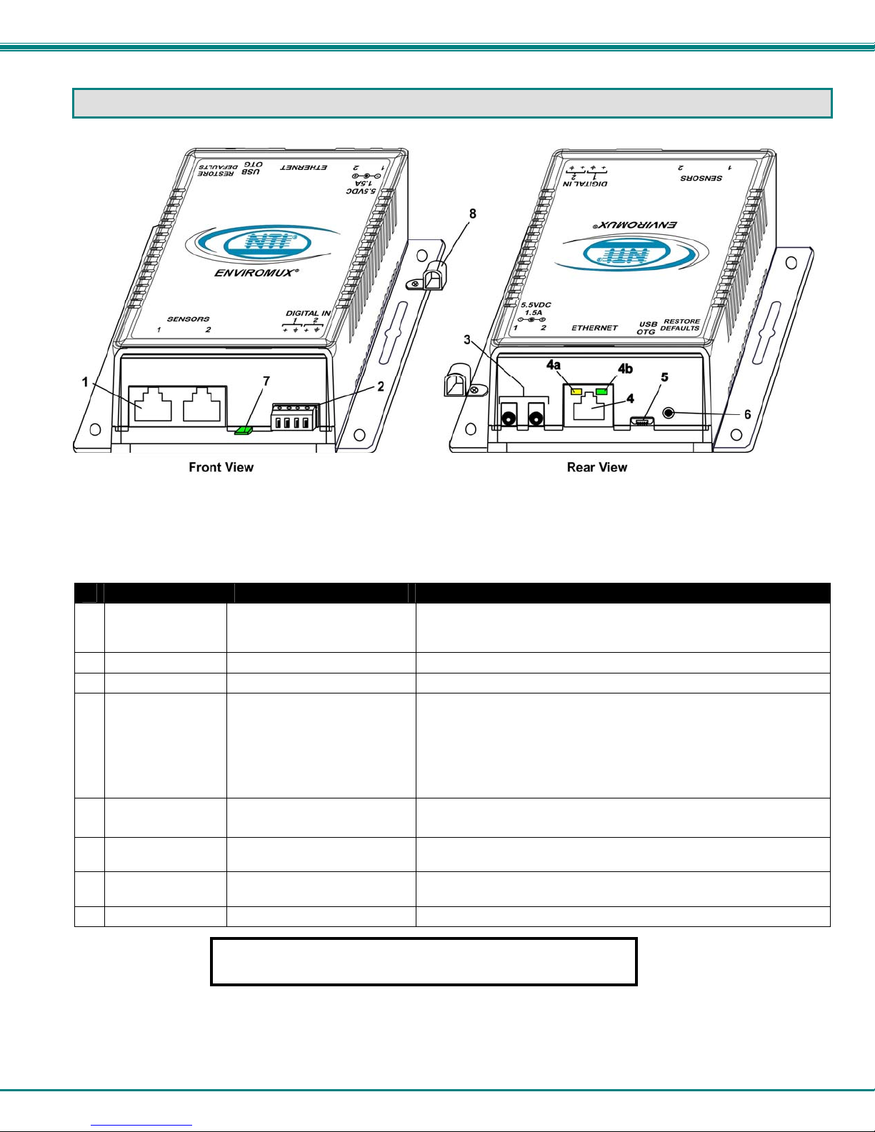
#
LABEL CONNECTOR/LED DESCRIPTION
1 Sensors
2 DIGITAL IN
3 5.5V 1.5A
4 Ethernet
5 USB OTG
6 Restore Defaults
7 ----
8 ----
RJ45 female connectors For connection of optional temperature/humidity sensors (The left
port is "#1", the right port is "#2" as listed in the Summary Page on
Page 14.)
Wire terminal block For connecting dry-contact and liquid detection sensors
3.5x1.3mm Power Jacks For connection of power supply(s)
RJ45 female connector For connection to an Ethernet for remote multi-user control and
monitoring
• 4a-Yellow LED– illuminated when Ethernet link is present,
• 4b- Green LED - indicates 100Base-T activity when illuminated,
Micro USB female
connector
Push button For manually resetting the ENVIROMUX to default settings- a
Sensor Integrated temperature sensor (-T model) or temperature/humidity
Cable Restraint For securing the power cable
Connection of a USB Flashdrive to the USB OTG port is not
supported as of this printing.
For connecting USB Modem or Flashdrive (using supplied adapter
cable)
momentary press will activate
sensor (-TRHP model).
strobing indicates activity on the Ethernet port
10Base-T activity when dark
3
Page 9
NTI Micro Environment Monitoring System
INSTALLATION
Mounting
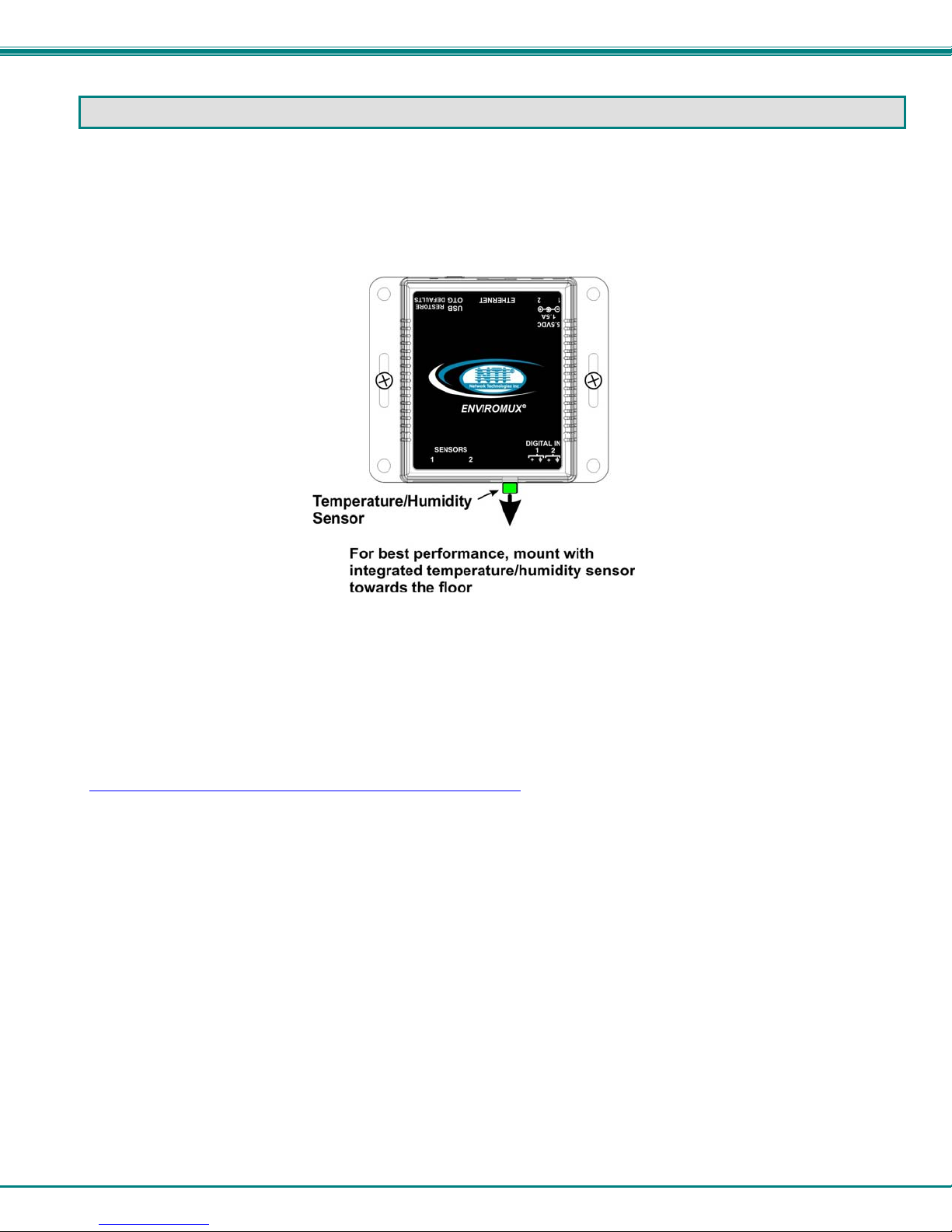
Mount the ENVIROMUX in any dry location convenient for connection of the sensors, Ethernet cable, modem and power
supply(s). The operating environment must be within -4°F to 185°F (-20°C to 85°C) with a relative humidity of 0 to 99% (noncondensing). When mounting the unit vertically, for best results mount the case with the integrated temperature sensor
positioned towards the floor.
Figure 1- Mount with sensor towards the floor
Connect Sensors
ENVIROMUX-MICRO-T(RHP) units are compatible with: ENVIROMUX-T-E7, ENVIROMUX-TRHM-E7 temperature and
temperature/humidity sensors as well as other types of sensors. For a complete list, visit our website at
http://www.networktechinc.com/environment-monitor-micro.html
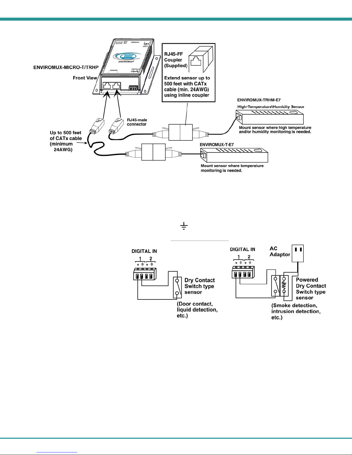
Connect the desired sensors (sold separately) to the available ports on the ENVIROMUX. Plug the RJ45 connectors to either of
the two RJ45 ports marked "SENSORS". Mount the sensors according to their individual operating characteristics. Power-cycle
the ENVIROMUX after sensors have been plugged-in.
Note: The maximum CAT5 cable length for attachment of temperature and humidity sensors in the
ENVIROMUX-MICRO-T(RHP) is 507 feet using minimum 24AWG cable.
Note: Mounting the temperature sensor in the path of a fan or on a heated surface may affect the accuracy of the
sensor’s readings.
4
Page 10
NTI Micro Environment Monitoring System
Figure 2- Connect Sensors
Up to two dry-contact sensors can also be connected. Sensors with 16-26 AWG connection wires that operate on 5V at 10mA
maximum current may be used. A contact resistance of 10kΩ or less will be interpreted by the ENVIROMUX as a closed contact.
The maximum cable length for attachment of contact sensors is 1000 feet.
To install the dry-contact sensor(s) to “DIGITAL IN” terminals:
A. Attach the positive lead to a terminal corresponding to a "+" marking on the ENVIROMUX and the ground lead
to the next terminal to the right that will correspond to a marking on the ENVIROMUX. Tighten the set
screw above each contact. Terminal sets are numbered 1-2.
Note: The terminal block is
removable for easy sensor
wire attachment if needed.
B. Mount the sensors as desired.
Figure 3- Terminal block for dry-contact sensors
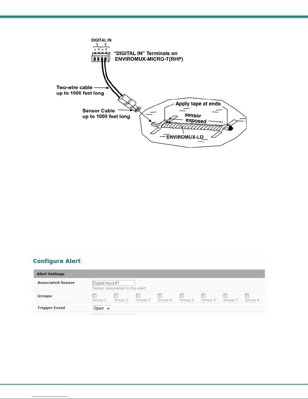
Optionally, connect the two-wire cable from a liquid detection sensor (Figure 4) to a set of “DIGITAL IN” contacts.
The twisted orange sensing cable should be placed flat on the surface (usually the floor) where liquid detection is desired. If tape
is required to hold the sensor in place, be sure to only apply tape to the ends, exposing as much of the sensor as possible. At
least 5/8" of the sensor must be exposed for it to function.
5
Page 11
NTI Micro Environment Monitoring System
Figure 4- Secure liquid detection sensor with tape
NOTE:
When installing the ENVIROMUX-LD-LC, it is very important to assure the sensing cable does not cross over itself or
cross conductive surfaces to avoid false triggers.
To test the ENVIROMUX-LD(-LC);
1. Configure the sensor (page 17). (Normal Status set to “Open”)
2. Submerge at least ½ inch of the exposed twisted orange wire (not the wrapped end) for up to 30 seconds. Do NOT use
distilled water as water must be conductive.
3. Monitor the sensor (page 14) to see the sensor “Value” change from “Open” (dry) to “Closed” (wet).
4. Dry the exposed area of sensor and the sensor “Value” should change back to “Open” within 30 seconds.
Figure 5- Portion of Water Sensor configuration page
6
Page 12
NTI Micro Environment Monitoring System
Ethernet Connection
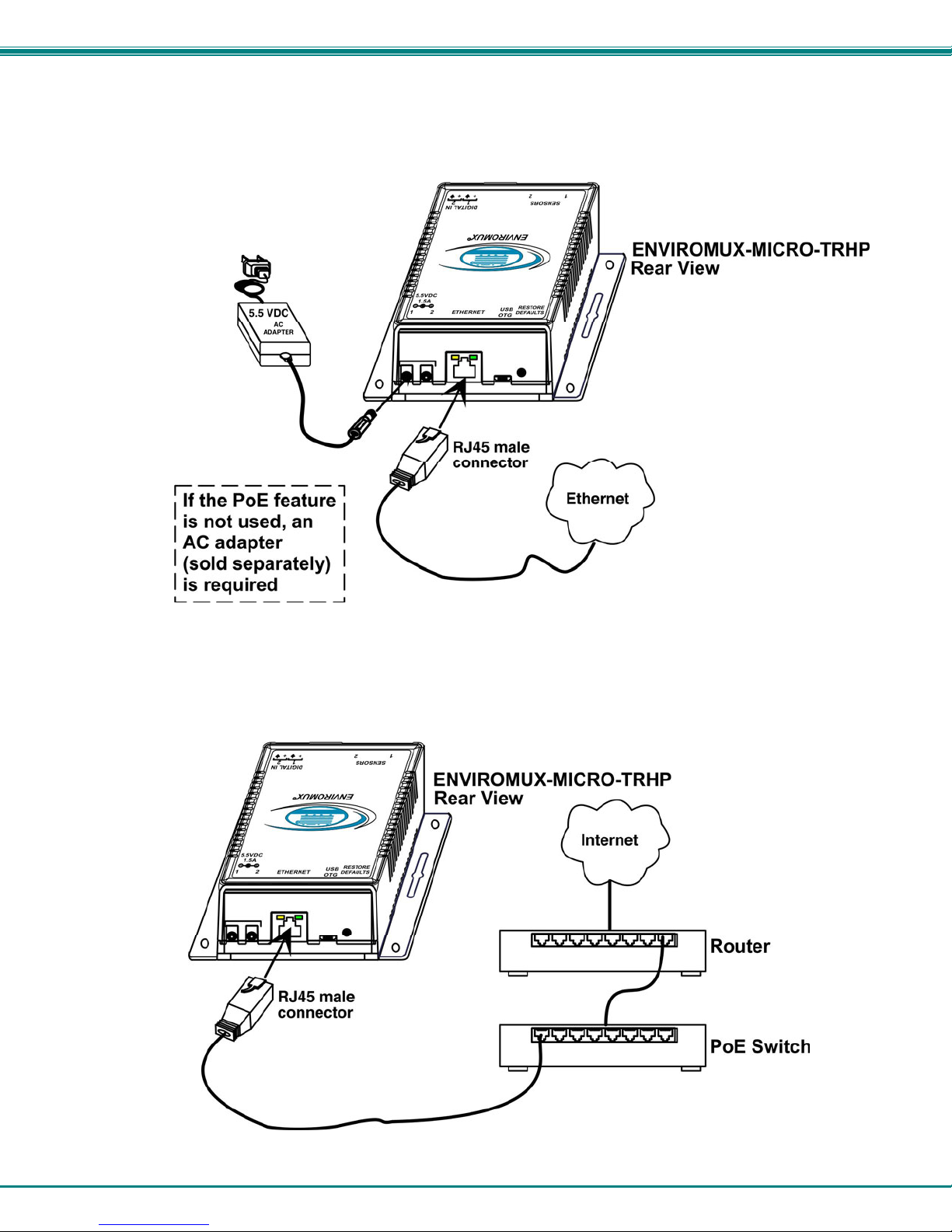
Connect a CAT5 patch cable (RJ45 connectors on each end wired pin 1 to pin 1, pin 2 to pin 2 etc) from the local Ethernet
network connection to the connector on the ENVIROMUX marked "Ethernet".
Figure 6- Connect ENVIROMUX-MICRO to the Ethernet
Note: A direct Ethernet connection can be made with a PC using the same CAT5 patch cable if desired.
7
Page 13
NTI Micro Environment Monitoring System
Connect the Power
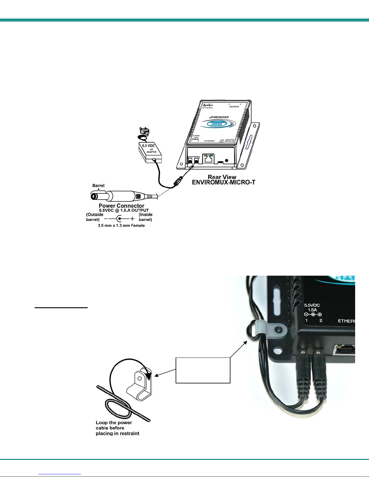
Note: Sensors should be connected before supplying power to the ENVIROMUX.
1. Connect the AC adapter to one of the connections marked "5.5VDC 1.5A” (either 1 or 2) on the ENVIROMUX and plug it
into an outlet.
Figure 7- Connect the AC adapter and power-up
If you have purchased the ENVIROMUX-TRHP and have connected it to a POE router, an external power supply will not be
needed as long as the router supports the IEEE 802.3af or 802.3at standards. (The Cisco Discovery Protocol is not supported.)
2. Use the NTI Discovery Tool (page 12) to configure network settings.
Cable Restraint
To provide a secure power connection to the ENVIROMUX, a cable restraint
has been provided. To secure the power cable, remove the screw that holds
the restraint to the ENVIROMUX, make a loop in the power cable and insert it
into the restraint. (The loop will prevent the cable from slipping through the
restraint.) Re-secure the restraint to the ENVIROMUX with the screw.
Loop the power
cable to prevent
slippage
Figure 8- Use cable restraint
8
Page 14
NTI Micro Environment Monitoring System
Connect a Modem
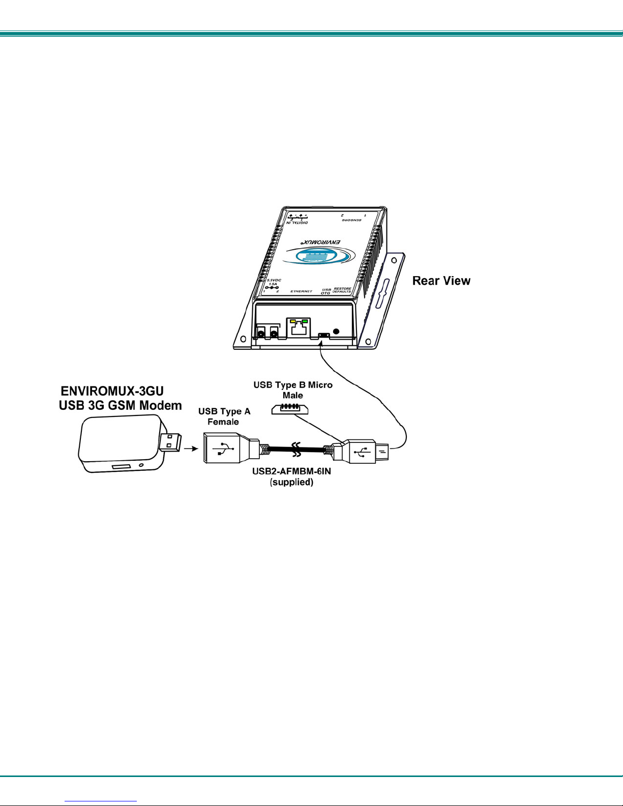
A USB GSM modem may be connected (ENVIROMUX-3GU) to use to send SMS alert messages to a contact’s cell phone. The
ENVIROMUX-3GU modem can be connected to the ENVIROMUX at the “USB OTG” port. . The same port can be used for
connecting a USB Flash Drive for data logging (page Error! Bookmark not defined.).
The phone number to be called for each user is configured under “User Settings-Contac t Settings” (page 29).
Note: A Mini SIM card (not included) must be installed in the modem for the modem to send messages. Make sure the
SIM card is for GSM communication (not CDMA) and that it is not locked (some SIM cards are "locked" to search for a
specific IMEI number of the phone to operate).
Figure 9- Connect a Modem
Cell phone Mini SIM card for GSM modem
A SIM card or Subscriber Identity Module is a portable memory chip used in some models of cellular telephones. It can be thought
of as a mini hard disk that automatically activates the phone (or in this case the GSM modem) into which it is inserted.
SIM cards are available in two standard sizes. The first is the size of a credit card (85.60 mm × 53.98 mm x 0.76 mm). The newer,
more popular miniature-version has a width of 25 mm, a height of 15 mm, and a thickness of 0.76 mm.
Some cellular service providers use Mini SIM cards. Verify with your service provider that their Mini SIM card will work with GSM
/ 3G GSM modems before making a purchase.
Note: The ENVIROMUX-3GU will send SMS messages only. No access to the ENVIROMUX is possible through the
modem.
9
Page 15

NTI Micro Environment Monitoring System
OVERVIEW
Administration
The ENVIROMUX can be managed and configured in any one of the following ways:
• Using Telnet protocol via the Ethernet Port.
• Using the web interface (HTTP/HTTPS protocol) via the Ethernet Port.
The following administrative controls are available in the ENVIROMUX, thru the menu.
• View or modify the administrator & user parameters (passwords, sensor alert subscriptions, admin access, etc.)
• View or modify the network parameters (e.g. IP Address, Gateways, DNS, etc.)
• View and clear system event logs
• Firmware upgrades for the ENVIROMUX (over Ethernet)
• View or modify sensor, and IP device configurations
General Functions
Sensor Alerts
A high and low threshold limit can be set for each temperature or humidity sensor. When a sensor takes a reading that is outside
a threshold, an alert notification is generated. The user can specify the frequency of alert notifications to match his or her
schedule. Also, there will be some hysteresis involved with alert notifications. This means if a sensor’s readings are moving in
and out of the threshold boundaries within a configurable period of time, additional alert notifications wil l not be sent. After an alert
is activated, it remains persistent even if the condition of the sensor returns back to normal, until the user acknowledges or
dismisses that alert. The user has the option to set the unit to auto-clear the alert if the sensor’s status returns to normal, and the
user can be notified if the condition goes back to normal. Alert notifications will be provided through four main methods: visible
notification via one of the user interfaces (alert on webpage, alert in text menu), emails, SMS messages and/or SNMP traps.
IP Monitoring & Alerts
Individual IP addresses can be monitored. The ENVIROMUX will ping each address, and if a response is received, the IP
address status is considered to be “OK”’. If no response, the user will have the option to configure the ENVIROMUX for an alert
will be logged and sent. The user can configure the timeout for a response and the number of retries before signaling an alert.
The ENVIROMUX can also be configured to monitor the IP addresses of the network switches and routers to which these devices
are connected, so as to determine if the problem is due to a lack of response from the device or a network failure. Alert
notifications will be provided through four main methods: visible notification via one of the user interfaces (alert on webp age, al ert
in text menu), emails, SMS messages and/or SNMP traps.
Event Log
The ENVIROMUX maintains an event log. The event log includes power-ON, system, and alert notifications, as well as user alert
handling. The maximum number of log entries is 200, and these entries are sorted in chronological order. The log can be viewed
at any time through the web interface. Log entries can be removed individually or all at once.
Data Log
The ENVIROMUX maintains a data log. The data log includes readings taken from sensors, IP devices, and connected
accessories being monitored. The log will record data for up to 30 days, at 1 minute intervals erasing the oldest data to make
room for new. The log can be viewed at any time through the web interface, and can be saved as a text file in either Epoch time
format or standard date/time format. Log entries can be cleared with the press of a button. The text file can be sent to any user
automatically via syslog and/or email.
10
Page 16

NTI Micro Environment Monitoring System
Email
The ENVIROMUX can access an SMTP server to send outgoing email. Outgoing email would contain pre-formatted alert
notifications. Email addresses can be configured through the web interface. Each user (up to 8) can have their o wn ema il
address. For assistance in setting up Email, see page 45.
The email messages sent by the ENVIROMUX have a fixed format. A sample message is shown below:
Subject: Message from E-MICRO P02 [Alert #1]
SENSOR: Test Switch 1
MESSAGE: Sensor value crossed over critical thresholds
VALUE: Closed
UNIT INFO: 192.168.1.24,00:0b:82:15:02:c3
SNMP
The ENVIROMUX can send alerts as SNMP traps when a sensor or IP device enters/leaves alert mode and for all log events.
Using an SNMP MIB browser, a user can monitor all sensor statuses and system IP settings.
The destination for SNMP traps can be configured for each user.
Note: The SNMP MIB file (micro-v1-xx.mib), for use with an SNMP MIB browser or SNMP trap receiver, can be found on
the manual CD. Click on the link to open the file, and then save the file to your hard drive to use with the SNMP MIB
browser or SNMP trap receiver.
GSM Modem
An external GSM modem can be connected to allow the system to send alert notifications via SMS messages. When a sensor
crosses a threshold or IP device become inactive, an alert notification can be formatted to SMS message and the modem can
transmit the message to all users that subscribe to the applicable sensor group.
Security
User Settings
In order to configure and operate the ENVIROMUX, each user must login with a unique username and password. The
Administrator can configure each user’s settings as User or Administrator. An Administrator has access to all configurations and
controls. A user can monitor sensors and IP devices. A user can edit his/her own account. Users cannot configure the alert
settings.
Secure Connections
The ENVIROMUX supports secure connections using HTTPS.
Authentications
The ENVIROMUX supports local authentication with up to 16 character usernames and passwords.
Encryption
The ENVIROMUX supports 256-bit AES encryption.
11
Page 17
NTI Micro Environment Monitoring System
DEVICE DISCOVERY TOOL
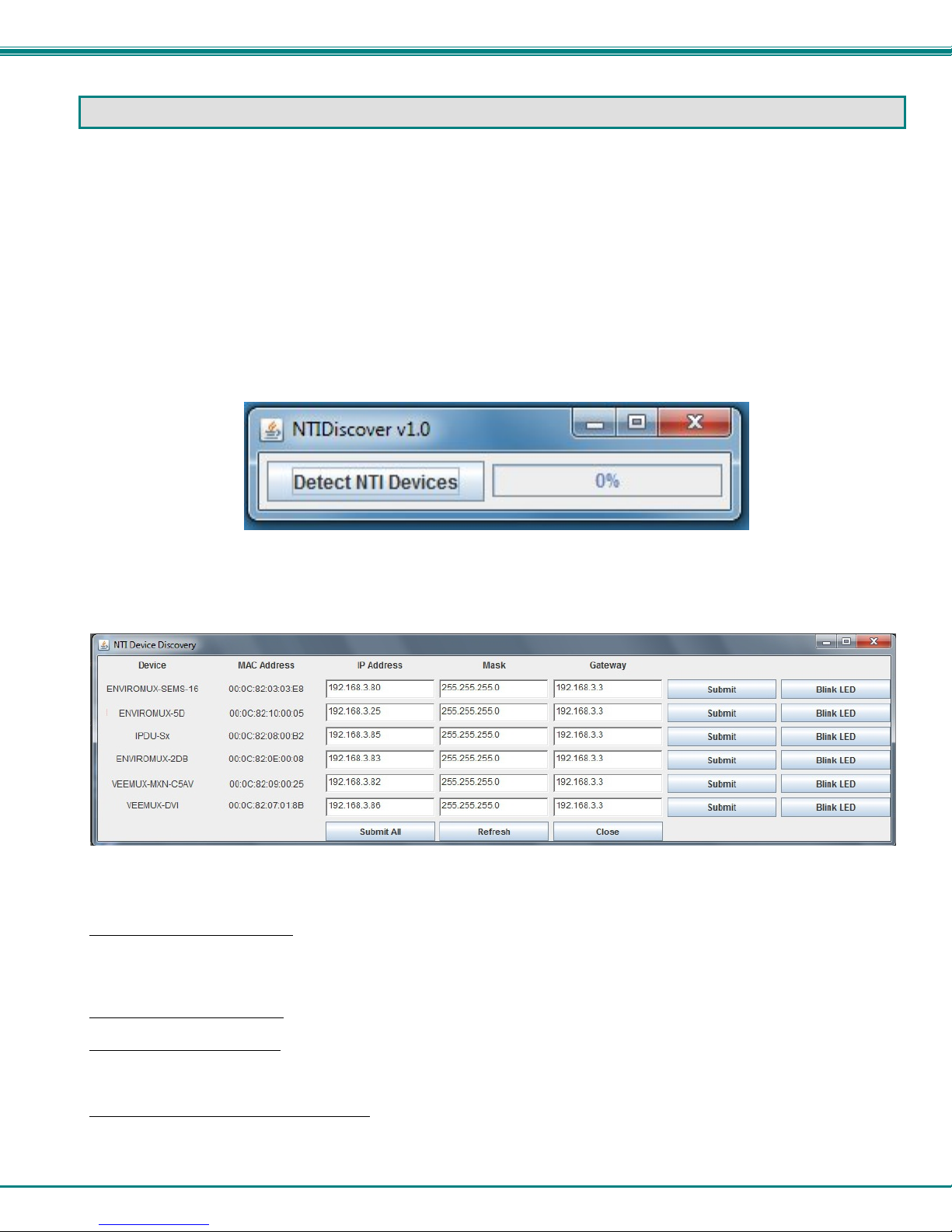
In order to easily locate NTI Devices on a network, the NTI Device Discovery Tool may be used. A link to the Discovery Tool is
provided on the web page that appears when you insert the instruction manual CD provided into your CD ROM drive. Either click
on the link or browse the CD to locate the NTIDiscover.jar file. The Discover Tool can be run from the CD or it can be saved
to a location on your PC. Either way, to open it just double-click on the file NTIdiscover.jar . This will open the NTI Device
Discovery Tool.
Note: The Device Discovery Tool requires the Java Runtime Environment (version 6 or later) to operate. A copy of Java
version 6 is provided on the CD and a link to the web page from which it can be downloaded and installed is also on the
CD.
Note: The computer using the Device Discovery Tool and the NTI Device must be connected to the same subnet in order
for the Device Discovery Tool to work. If no devices are found, the message “No Devices Found” will be displayed.
Tip: If your Windows program asks which program to open the NTIDiscover.jar file with, select the Java program.
Figure 10- Device Discovery Tool
Click on the “Detect NTI Devices” button to start the discovery process. After a short time, the tool will display all NTI devices on
your network, along with their network settings.
How to Use the Device Discovery Tool
To Change a Device’s Settings
at a time) and click on the Submit button on that row. Update the IP Address, Mask, and Gateway as needed, one at a time. If
the tool discovers more than one device, the settings for all devices can be changed in the same fashion. (The “Submit All” button
is not supported by this product.)
To Refresh the list of devices, click on the Refresh button.
To Blink the LEDs of the unit, click on the Blink LED button (This feature is not supported on all products.) The Blink LED
button will change to a “Blinking….” button. The LEDs of the unit will blink until the Blinking… button is clicked on, or the NTI
Device Discovery Application is closed. The LEDs will automatically cease blinking after 2 hours.
To Stop the LEDs of the unit from blinking, click on the Blinking… button. The Blinking…. button will change to a Blink LED
button.
, within the row of the device whose settings you wish to change, type in a new setting (one field
12
Page 18
NTI Micro Environment Monitoring System
OPERATION VIA WEB INTERFACE
A user may monitor and configure the settings of the ENVIROMUX and any sensor connected to it using the Web Interface via
any web browser (see page 2 for supported web browsers). To access the Web Interface, connect the ENVIROMUX to the
Ethernet (page 7). Use the Device Discovery Tool (page 12) to setup the network settings. Then, to access the web interface
controls, the user must log in.
Note: In order to view all of the graphics in the Web Interface, the browser’s JavaScript and Java must be en abled.
By default, the ENVIROMUX is configured to dynamically assign network settings received from a DHCP server on the network it
is connected to. (This can be changed to a static IP address to manually enter these settings in the Network Settings on page 25.)
The ENVIROMUX will search for a DHCP server to automatically assign its IP address each time the unit is powered up. If the
ENVIROMUX does not find a DHCP server, the address entered into the static IP address field (page 25 -default address shown
below) will be used. If a DHCP server on the network has assigned the IP address, use the Device Discovery Tool to identify the
IP address to enter when logging in to the ENVIROMUX.
Note: The computer using the Device Discovery Tool and the NTI Device must be connected to the same subnet in order
for the Device Discovery Tool to work. If no devices are found, the message “No Devices Found” will be displayed.
Log In and Enter Password
To access the web interface, type the current IP address into the address bar of the web browser. (The default IP address is
shown below):
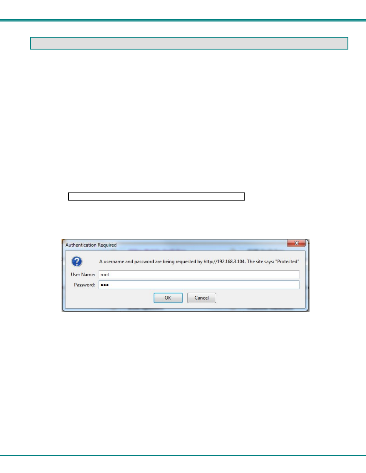
A log in prompt requiring a user name and password will appear:
http://192.168.1.24
Figure 11- Login prompt to access web interface
User Name = root
Password = nti
(lower case letters only)
Note: usernames and passwords are case sensitive
13
Page 19
NTI Micro Environment Monitoring System
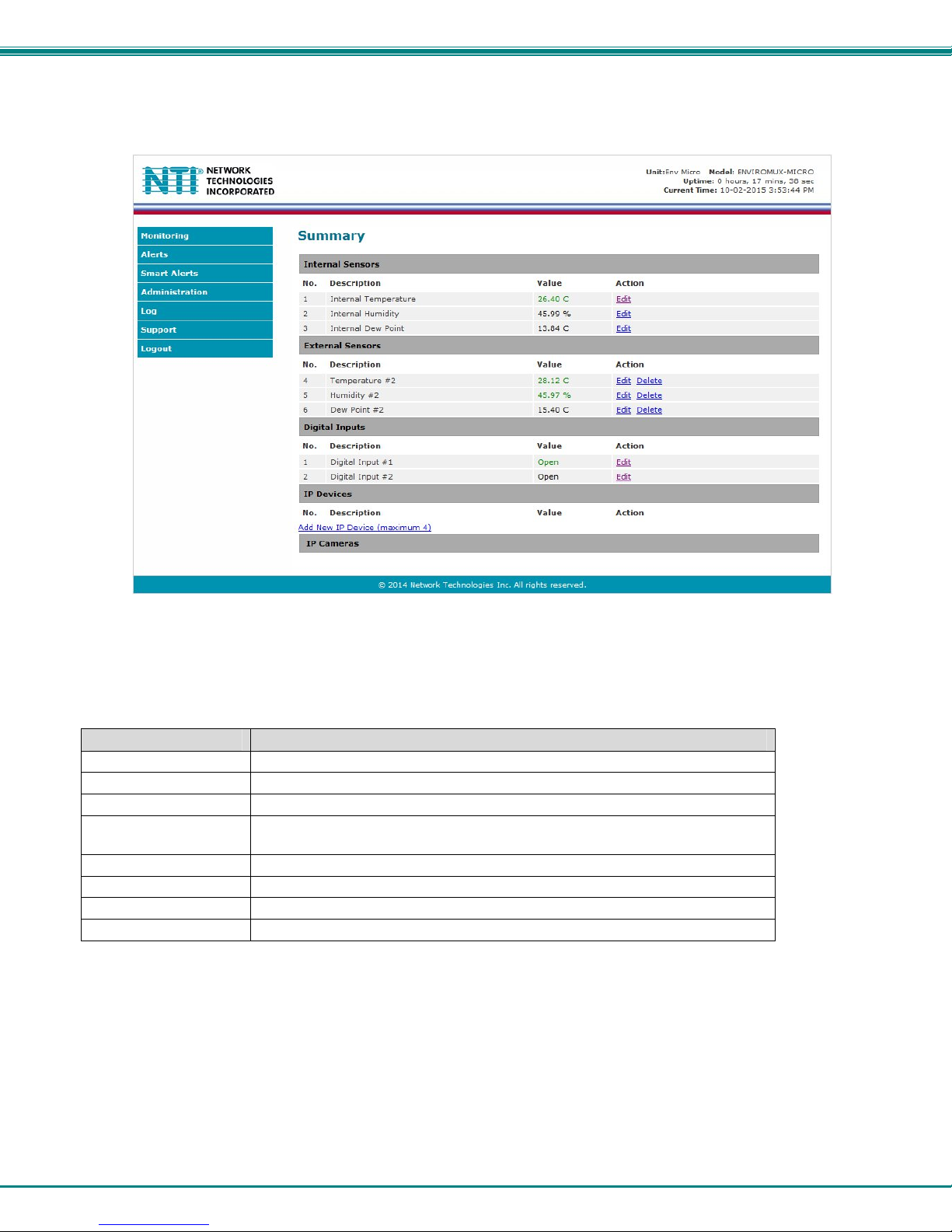
With a successful log in, the “Summary” page with a menu at left will appear on the screen:
Figure 12- Summary page
From this initial page, the user can use the menu to the left to manage all the functions of the ENVIROMUX.
Function Description
SUMMARY Monitor the sensors, accessories, and IP devices of the ENVIROMUX (next page)
ALERTS View and configure how alerts will be communicated to users (page 17)
SMART ALERTS View and configure how smart alerts will be communicated to users (page 17)
ADMINISTRATION Configure all system, network, multi-user access, and security settings as
well as upgrade firmware (page 24)
LOG View and manage the Event and Data Logs (page 33)
IP DEVICES View the status of IP Devices located anywhere
SUPPORT Links for downloading a manual, the MIB file, or firmware upgrades
LOGOUT Log the user out of the ENVIROMUX web interface
14
Page 20
NTI Micro Environment Monitoring System
Summary
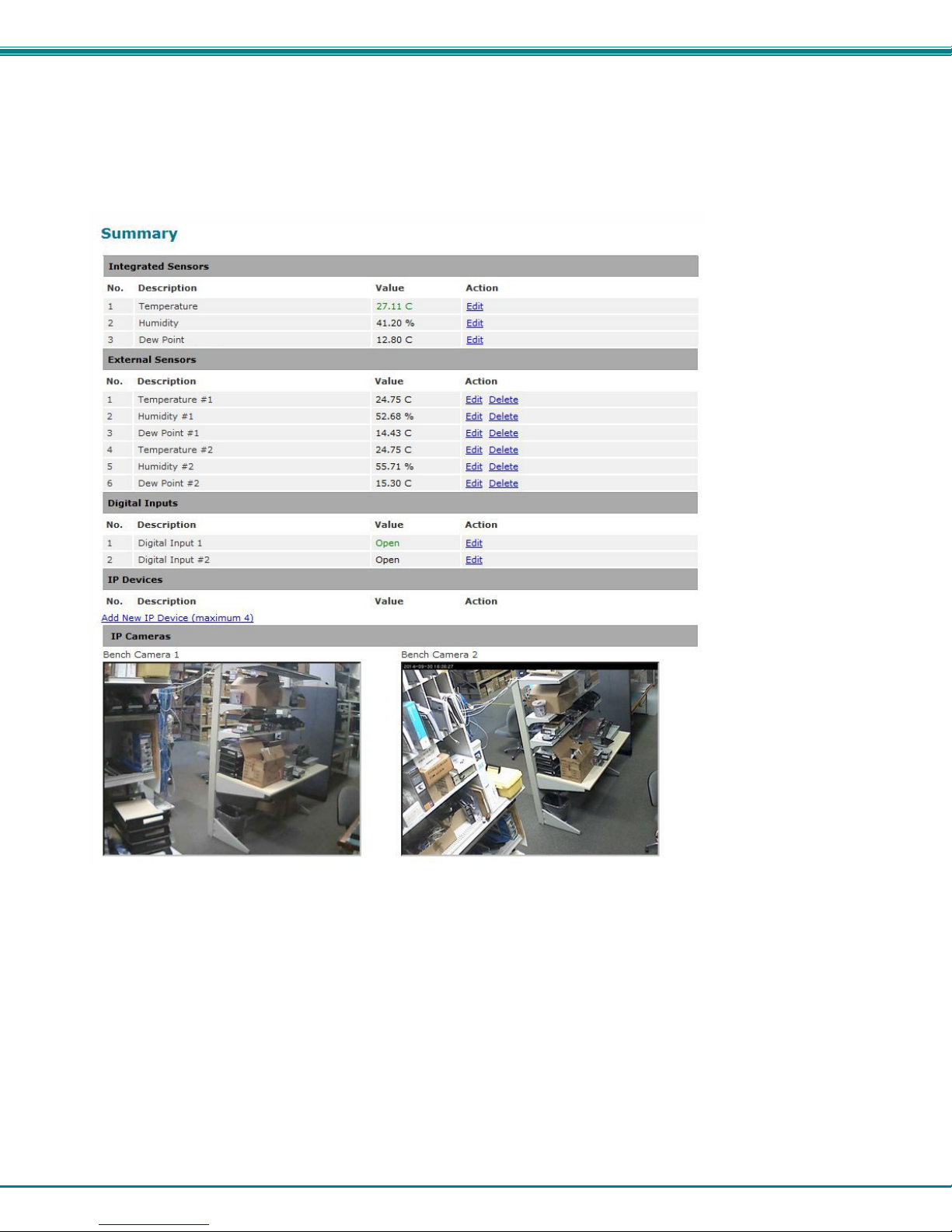
Under Summary, the status of all sensors and IP Devices being monitored by the ENVIROMUX is displayed. Links to edit their
description and for temperature and/or humidity sensors the scale can be changed between Fahrenh eit and Celsius.
Figure 13- Summary page
15
Page 21
NTI Micro Environment Monitoring System
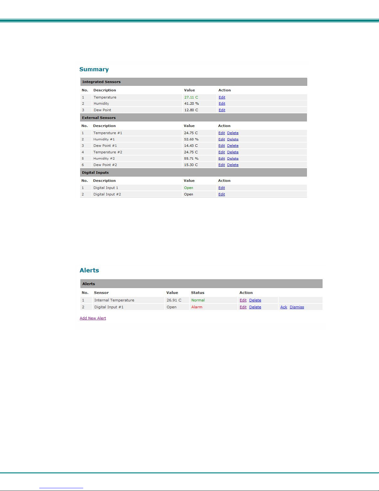
If the sensor is in alert status, the value will be shown in red text. To respond to the alert, open the Alerts page.
Figure 14- List of alerts configured
From the Alerts page, the user has the option to either acknowledge the alert or dismiss it. If the user acknowledges the alert,
no additional alert messages will be sent during that alert status cycle. If the user dismisses the alert, another alert message will
be sent once the “notify again after” time designated on the configuration page (page 19) elapses.
The administrative user can open the alert configuration page by clicking on the Edit button under “Action” for that sensor. From
the alert configuration page the user can apply settings to control how or if alert messages are sent in the event the sensor is in
alert status.
16
Page 22
NTI Micro Environment Monitoring System
Sensor Settings
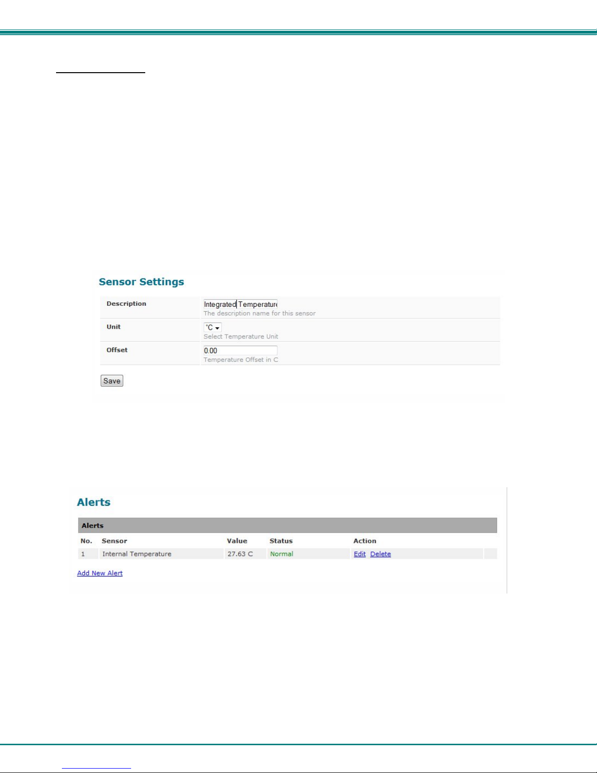
To change the settings for a sensor, click on Edit on the Overview page. From the Sensor Settings page, you can change the
description of the sensor as it appears in the overview page and as it will appear on alert messages you receive. For
temperature sensors, you can also assign the unit of measure that is used for measurement and reporting.
Offset
The integrated temperature sensor is most accurate in environments where there is plenty of airflow around it. When the
ENVIROMUX-MICRO is mounted in a location with little or no airflow, the integrated temperature sensor may be less accurate
due to heat generated by nearby electronics. An “Offset” field is provided (for the integrated temperature sensor only) to allow
you to enter a value that will compensate for stagnant air. The recommended Offset value in environments with little or no air
movement is -1.5°C. The field will accept a value between -2.5° to 0° C.
Note: This value is always in Centigrade, even if the Temperature Unit is set to “°F”.
To determine exactly how much the offset needs to be for your specific environment, you may want to use an accurate
temperature measuring device in the same location as reference to assign a correction value to this field. Assign a value that will
enable the reported temperature value report on the summary page to match your reference.
Figure 15- Sensor settings
Alerts
To view a list of what alerts have been configured for the sensors or IP devices, select Alerts from the side menu.
Figure 16- List of configured alerts and their status
17
Page 23
NTI Micro Environment Monitoring System
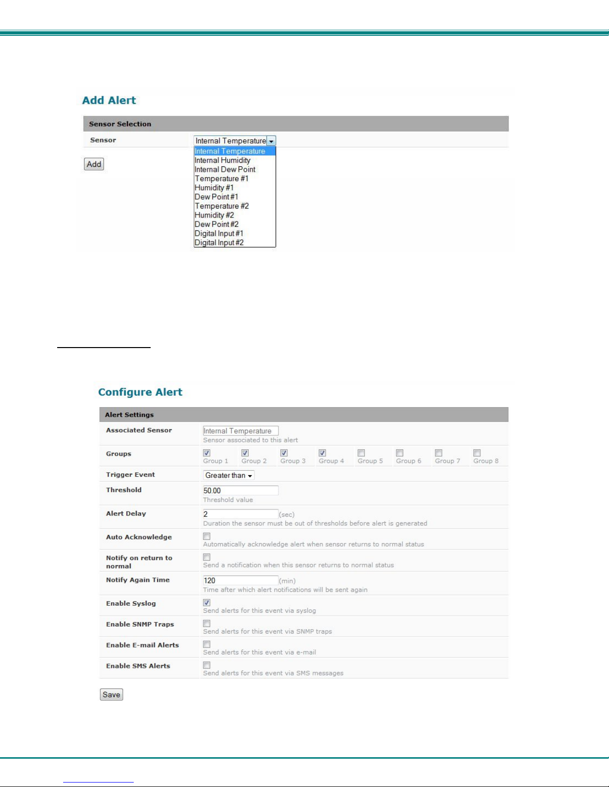
To add an alert, click on “Add New Alert”. From the drop down box next to “Sensor”, select a sensor or IP device to configure an
alert for.
Figure 17- Select a sensor to add an alert configuration for
To edit settings for an alert, click on “Edit” next to the alert. The “Configure Alert” page will appear.
Configure Alerts
To configure how alerts are triggered and reported, the Configure Alert page is provide d. F rom this page the user can determine
who gets alert message and how.
Figure 18- Alert Configuration page for Temperature/Humidity sensors
18
Page 24
NTI Micro Environment Monitoring System
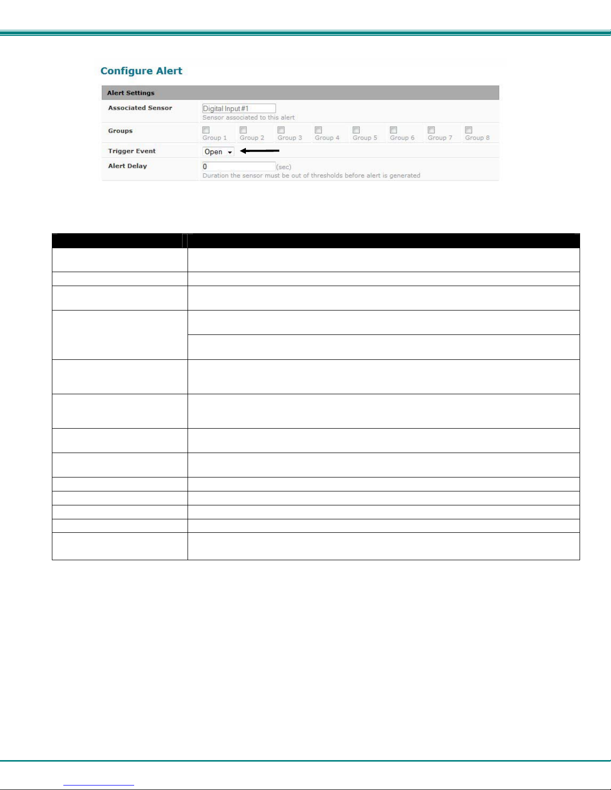
Figure 19- Alert configuration for Digital sensor- minor difference
Alert Settings Description
Description The description of the sensor that will be viewed in the Summary page and in the body of alert
messages - cannot be changed from this page (see Sensor Settings-page 17)
Group Assign the alert to any group 1 -8
Units This lets the operator choose between Celsius and Fahrenheit as the temperature
measurement unit. (not applicable to digital sensors)
Trigger Event
Threshold The user must define the lowest or highest (depending on the value assigned to “Trigger
Alert Delay The alert delay is an amount of time the sensor must be in an alert condition before an alert is
Auto Acknowledge Place a checkmark in this box to have alert notifications in the summary page return to normal
Notify on Return to Normal The user can also be notified when the sensor readings have returned to the normal range by
Notify Again Time Enter the amount of time in minutes (1-999) before an alert message will be repeated
Enable Syslog Place a checkmark in this box to have alert notifications sent via Syslog messages
Enable SNMP traps Place a checkmark in this box to have alert notifications sent via SNMP traps (v2c)
Enable Email Alerts Place a checkmark in this box to have alert notifications sent via Email
Enable SMS Alerts
Be sure to press the Save button to save the configuration settings.
Choose whether a threshold value greater than or less than the value entered und er “threshold”
will trigger an alert (not applicable to digital sensors)
Select whether a sensor that is Open or one that is Closed will trigger an alert (digital sensors
only)
Event”) acceptable value for the sensor. If the sensor measures a value that exceeds this
threshold, the sensor will move to alert status.
sent. This provides some protection against false alarms. The Alert Delay value can be set
for 0-999 seconds.
state automatically when sensor readings return to normal.
selecting the "Notify on return to normal" box for a sensor.
Place a checkmark in this box to have alert notifications sent via SMS messages (requires a
modem)
More about Groups
Groups are used to create a common relationship between sensors, IP devices, etc. and their alert messages. Each item being
monitored can be assigned to one or more groups (up to 8). Users (a maximum number of 9 including the root user) can receiv e
alert messages from items in one or more groups (see user configuration on page 29).
19
Page 25
NTI Micro Environment Monitoring System
Smart Alert
Smart Alerts enable the ENVIROMUX to contact users when specially configured circumstances exist for defined sensors. Smart
Alerts will respond to 1 or more alert conditions independent of the alert configurations for each sensor configured on page 18.
Assorted conditions can produce configurable events that can then be used in numerous scenarios to produce Smart Alert
messages that are sent to users.
To begin, Events must be defined and configured. Events are sensor conditions to be notified of. Events logged based on the
sensor configurations described on page 18 will be managed separately from events lo gged by these pre-defined Events. Sensor
configuration for these Events will have no impact on the general configuration of your sensors. Pre-defined Events provide more
control over what you want to be notified of.
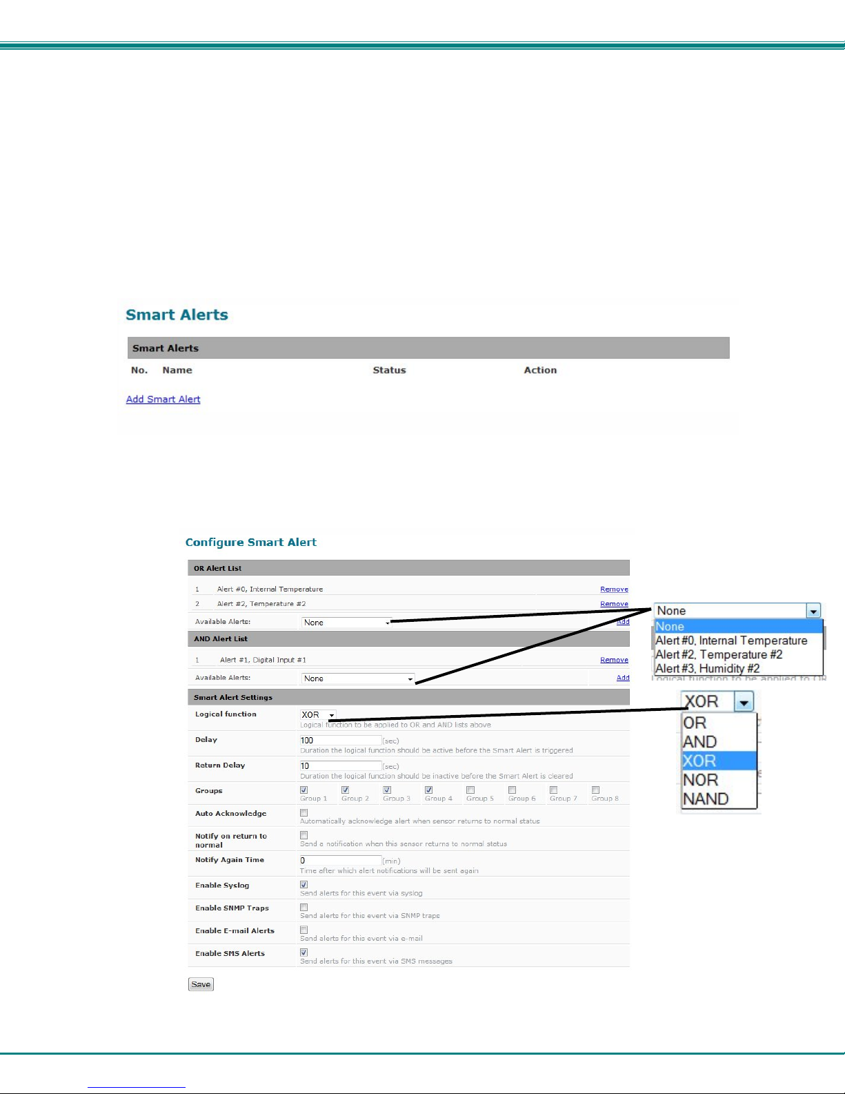
From the side menu, select “Smart Alerts”.
Figure 20- Smart Alerts page
On the Smart Alerts page, click on “Add Smart Alert”.
Figure 21- Sensor to be used for a predefined event
20
Page 26

NTI Micro Environment Monitoring System
OR Alerts
Available Alerts Select from the predefined available Alerts (Figure 21) to have OR logic applied when that alert
is triggered. One or more may be selected for a more complex configuration.
AND Alerts
Available Alerts Select from the predefined available Alerts (Figure 21) to have AND logic applied when that
Smart Alert Settings
Logical Function Logical function to be applied to the output of the logical status of the OR and AND lists to
Delay The amount of time the Smart Alert must be in an alert condition before a Smart Alert message
Return Delay The amount of time the logical function should be inactive before the Smart Alert will be cleared
Groups Assign the Smart Alert to any group 1 -8 (see also page 19)
Auto Acknowledge Place a checkmark in this box to have alert notifications in the summary page return to normal
Notify on Return to Normal The user can also be notified when the Smart Alert conditions have returned to the normal (non-
Notify Again Time Enter the amount of time in minutes (0-999) before an alert message will be repeated
Enable Syslog Place a checkmark in this box to have alert notifications sent via Syslog messages
Enable SNMP traps Place a checkmark in this box to have alert notifications sent via SNMP traps (v2c)
Enable Email Alerts Place a checkmark in this box to have alert notifications sent via Email
Enable SMS Alerts
In the “OR” Alert List section, select from the drop-down list which alert configuration(s) to associate with the “OR” part of the
Smart Alert equation. After each is selected, click “Add”.
For the “OR” logic to be effective, more than one would be selected. This would mean that either alert condition being triggered
would satisfy this half of the logic equation.
In the “AND” Alert List section, select from the drop-down list which alert configuration(s) to associate with the “AND” pa rt of the
Smart Alert equation. After each is selected, click “Add”.
For the “AND” logic to be effective, more than one would be selected. This would mean that both alert conditions would have to
be triggered to satisfy this half of the logic equation.
Next select the Smart Alert Settings to be used with your alert selections. The Logical function you select will determine the
combined situation that would trigger a Smart Alert message to be sent.
After all options are selected, click the “Save” button. This Smart Alert will now be added to the Smart Alerts page (Figure 20).
Only one Smart Alert can be defined.
alert is triggered. One or more may be selected for a more complex configuration.
determine when a Smart Alert should be generated.
Options include OR, AND, XOR, NOR and NAND
is triggered. This provides some protection against false alarms. The Delay value can be set
for 0-999 seconds or minutes.
state automatically when Smart Alert conditions return to normal.
triggered state) by selecting the "Notify on return to normal" box.
Place a checkmark in this box to have alert notifications sent via SMS messages (requires a
modem)
21
Page 27
NTI Micro Environment Monitoring System
More on Logical Functions
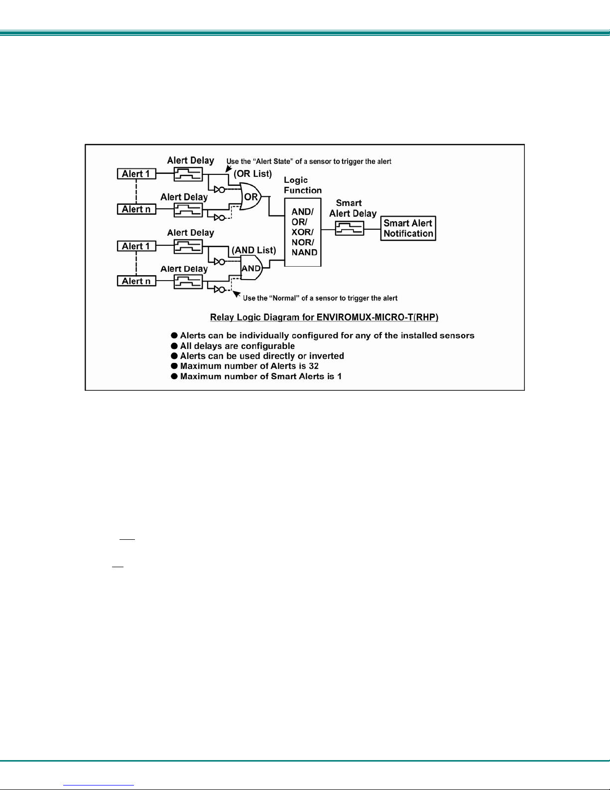
Using Logical Functions, you can select how to use or not use the reported state of an Alert. You can combine the information
from multiple Alerts to achieve an end result.
Figure 22- Event Logical Function Diagram
Smart Alert Rules:
• Any configured Alert can be applied to either the OR Alerts list or the AND Alerts list, or both lists.
• Alerts can be configured to be triggered by a sensor or monitored IP devic e in alert state or in normal state.
• Each list will generate an output value, the value to either send a n al ert (1), or not (0).
• If any
• All Alerts in the AND list must be triggered for the output value of the AND list to be 1.
Alert in the OR list is triggered, the output value of the OR list will be 1.
22
Page 28
NTI Micro Environment Monitoring System
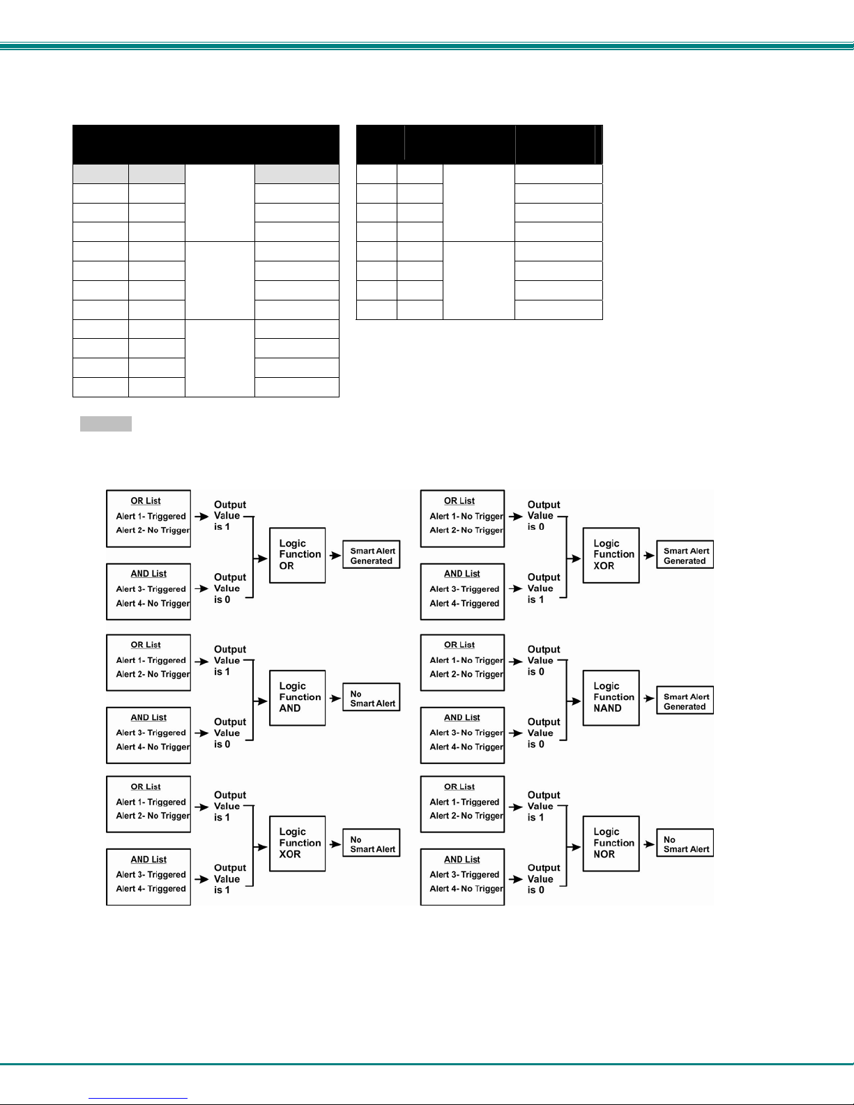
The Logical Function combines the two values to determine if a Smart Alert should be sent, as detailed in the table below:
OR
List
Example: If the OR list value is at 0, and AND list value is at 0, when the Logical Function is set to OR a Smart Alert will
NOT be generated.
AND
List
0 0 No 0 0 Yes
1 0 Yes 1 0 No
0 1 Yes 0 1 No
1 1
0 0 No 0 0 Yes
1 0 Yes 1 0 Yes
0 1 Yes 0 1 Yes
1 1
0 0 No
1 0 No
0 1 No
1 1
Logical
Function
OR
XOR
AND
Smart Alert
Generated
Yes 1 1
No 1 1
Yes
OR
List
AND
List
Logical
Function
NOR
NAND
Smart Alert
Generated
No
No
Figure 23- Examples of Smart Alert conditions
23
Page 29
NTI Micro Environment Monitoring System
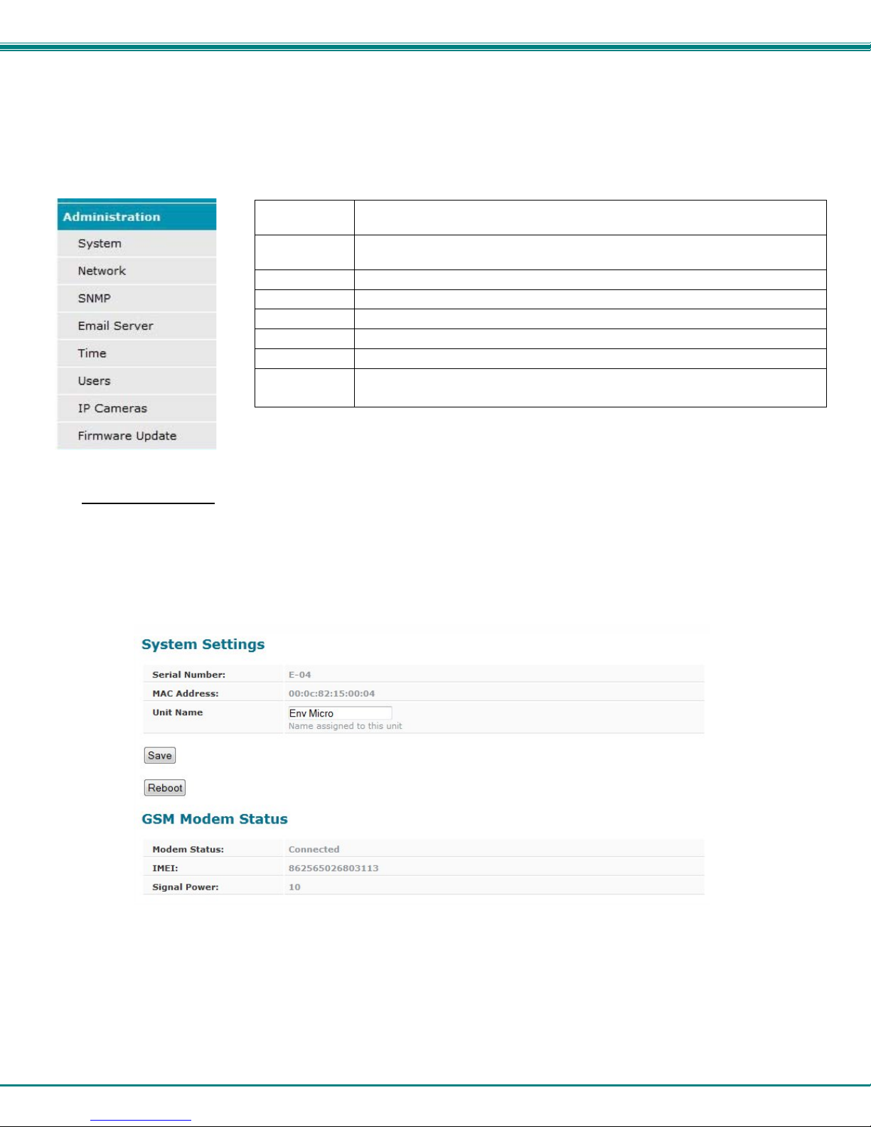
Administration
From the Administration section there are several sub sections for configuring the ENVIROMUX:
System Fields for applying time zone, date, time, NTP server, and backup and restore
configuration settings
Network Fields for providing all the network settings of the ENVIROMUX including IP
address and DNS settings
SNMP Fields for using SNMP
Email Server Fields for setting up the ENVIROMUX email account
Time Fields for setting time and date
Users Fields for assigning users, access privileges, passwords and contact settings
IP Cameras Fields for entering IP cameras to be monitored
Firmware
Update
For updating the firmware of the ENVIROMUX when improved software
becomes available.
System Settings
The System Settings section displays the serial number, MAC Address and Unit Name of the ENVIROMUX-MICRO. Only the
Unit Name is user-configurable. To view the System Configuration page, click on System from the Administration section of the
menu.
From the System Settings page the GSM Modem Status can also be viewed. When GSM Modem is connected (page 9), the
ENVIROMUX will automatically sense it and this page will display the “connected” status, the IMEI number, and the strength of the
signal the modem is receiving. Signal strength will vary between “0” (weakest) and “31 (strongest).
Figure 24- System Settings page
Reboot the System
The ENVIROMUX can be remotely rebooted by anyone with administrative privileges. Click the Reboot button to cause the
ENVIROMUX to reboot. This will disconnect any user and shut down all activity.
24
Page 30
NTI Micro Environment Monitoring System
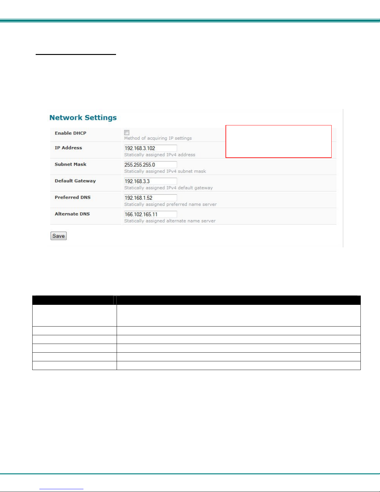
Network Configuration
From the Network Setup page the administrator can either choose to have the IP address and DNS infor m ation filled in
automatically by the DHCP server, or manually fill in the fields (use a static address). Settings can be entered for either the IPv4
or IPv6 protocols. To view the Network Configuration page, click on Network from the Administration section of the menu.
Note: If you select “DHCP” (default setting), make sure a DHCP server is running on the network the ENVIROMUX is
connected to.
Note: The values applied here are
for local (static) address
configuration only.
Figure 25- Network Settings page
Network Settings Description
Enable DHCP Leave this blank for between Static (manual) or enter a checkmark for DHCP (automatic IP
settings) Note: If you select “DHCP” (default setting), make sure a DHCP server is
running on the network the ENVIROMUX is connected to.
IP Address Enter a valid IP address (default address is 192.168.1.24)
Subnet Mask Enter a valid subnet mask (default value shown above)
Default Gateway Enter a valid gateway
Preferred DNS Enter a preferred domain name server address
Alternate DNS Enter an alternate domain name server address
25
Page 31
NTI Micro Environment Monitoring System
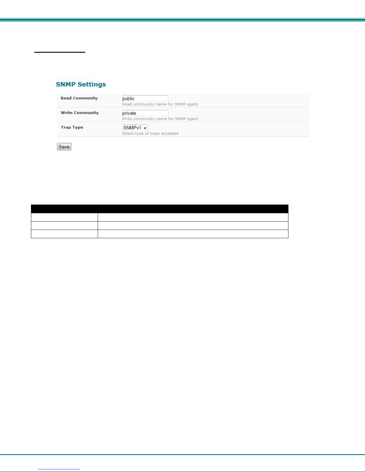
SNMP Settings
The SNMP Settings page contains the user configurable settings for using SNMP.
Figure 26- SNMP Settings
SNMP Settings
Read community Enter applicable read-only community name (commonly used- “public”)
Write community name Enter applicable read-write community name (commonly used- “private”)
Trap Type Select the type of traps that will be accepted by your software, v1 or v2c.
Read-Only Community Name
The SNMP Read-only community name enables a user to retrieve "read-only" information from the ENVIROMUX using the SNMP
browser and MIB file. This name must be present in the ENVIROMUX and in the proper field in the SNMP browser.
Read-Write Community Name
(not applicable as of this printing)
The SNMP Read-Write community name enables a user to read information from the ENVIROMUX and to modify settings on the
ENVIROMUX using the SNMP browser and MIB file. This name must be present in the ENVIROMUX and in the proper field in
the SNMP browser.
26
Page 32
NTI Micro Environment Monitoring System
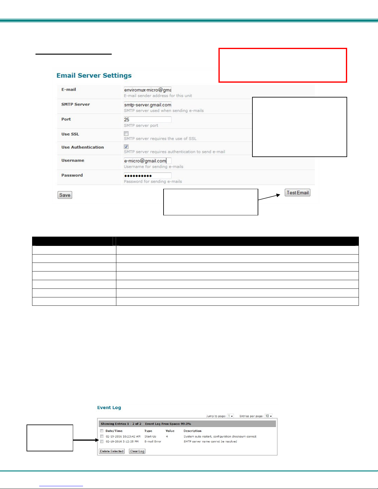
Email Server Settings
Use this button to make sure
your server and user email
settings are correct.
When using Gmail for the ENVIROMUXMICRO, be sure to turn ON the feature
“Enable less secure apps” under the Gmail
security settings
Common Port numbers:
Default: 25 (Not secure)
SSL: 465 (Secure)
Contact your network
administrator for required
settings.
Figure 27- Email Server Settings
Email Settings Description
E-mail Enter a valid email address for the ENVIROMUX-MICRO
SMTP Server Enter a valid SMTP server name (e.g. yourcompany.com)
Port Enter a valid port number (default port is 25, for SSL most use 465)
Use SSL Place a checkmark in the box if the SMTP server supports SSL
Use Authentication Place a checkmark in the box if the SMTP server requires authentication to send email
Username Enter a valid username to be used by the ENVIROMUX to send emails
Password Enter a valid password assigned to the ENVIROMUX username
If the administrator chooses to have the IP and DNS information filled in automatically via DHCP, the SMTP server and port
number still need to be entered for email alerts to work. If the SMTP server requires a password in order for users to send emails,
the network administrator must first assign a user name and password to the ENVIROMUX.
Note: The most commonly assigned SMTP server port number is "25". For SMTP servers that support SSL, the common port
number is 465.
Once the email server settings are configured and the user settings are configured (page 29), click on “Test Email” button to
verify that the configuration has been done correctly. Each configured user will receive an email from the ENVIROMUX-MICRO
email address that reads “Test Email Configuration” in the body of it.
If the message is not deliverable, due to wrongly entered settings or an invalid email address, an error will be recor de d in the
Event Log (page 33).
Email error in
Event Log
27
Page 33
NTI Micro Environment Monitoring System
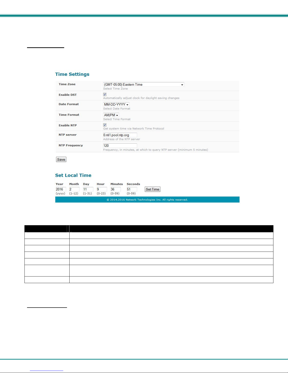
Time Settings
The Date and Time of the ENVIROMUX can be either manually setup to use an onboard clock or set to be synchroniz ed with an
NTP server.
Figure 28- Time and Date Settings
Time Settings Description
Time Zone Enter the appropriate time zone
Enable DST Apply a checkmark to have the time change according to Daylight Saving Time rules
Date Format Set for AM/PM or 24 Hour format
Time Format Enter the system time of day in hh:mm:ss format
Enable NTP Place a checkmark to enable the ENVIROMUX to automatically sync up with a time server via NTP
NTP server If the NTP is enabled, enter the Domain Name or IP address of the NTP server (the default NTP server is
0.nti1.pool.ntp.org
NTP Frequency Enter the frequency (in minutes) for the ENVIROMUX to query the NTP server (minimum is 5 minutes)
Click on Save when finished with Time Setting changes.
Set Local Time
Enter the date and your local current time of day. Then click “Set Time”. Entries here take immediate effect.
28
Page 34
NTI Micro Environment Monitoring System
Users
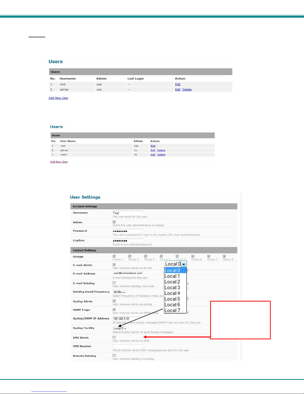
Select Users from the side menu to display a list of the users that have been configured to access the ENVIROMUX.
A maximum of 8 users (other than root) can be configured. From this page you can either choose to edit a user’s configuration,
delete them from the list, or add new users.
Figure 29- Users List
Click “Add New User” to add “userx” to the list. To delete a user and their configuration, click on “Delete” link.
Figure 30- User2 added- ready to configure
Click “Edit” to bring up the User Settings.
Enable SMS alerts in no
more than two user
configurations. The
ENVIROMUX-MICRO will
send SMS Alerts to a
maximum of two users.
Figure 31- User Settings
29
Page 35
NTI Micro Environment Monitoring System
When adding a new user, the Configure User page will open with the username “userx” assigned, where x = the next
consecutive number (up to 8) based on the quantity of users in the list (other than the root user). You can either leave the name
as “userx”, or change it to what you would like to see listed. With the name assigned, fill in the remaining information as needed.
Account Settings Description
Username Enter the desired username for this user
Admin Place a checkmark here if this user should have administrative privileges
Password Enter a password that a user must use to login to the system
A password must be assigned for the user’s login to be valid
Passwords must be at least 1 keyboard character.
Confirm Re-enter a password that a user must use to login to the system
Contact Settings
Group 1-8 Place a checkmark if the user should receive messages from sensors, accessories, or IP
devices in Group 1, 2, 3… thru 8 (see also pages 19 and 36 for group assignments)
Email alerts Place a checkmark if the user should receive messages via email
Email address Enter a valid email address if this user should receive email alert messages
Email datalog Place a checkmark if the user should receive sensor datalog reports via email
Datalog Email Frequency Select the frequency to receive datalog reports- 30min, 1hr, 2hr,4hr,6hr or 8hr increments
Syslog alerts Place a checkmark if the user should receive alerts via syslog messages
SNMP traps Place a checkmark if the user should receive alerts via SNMP traps
Syslog/SNMP IP address Enter a valid syslog/SNMP IP address for the user to receive syslog/SNMP messages (alerts
and/or data logs, as configured)
Syslog Facility Select a Syslog Facility for the messages to be sent to- Local0 thru Local7 (default is Local0).
SMS Alerts Place a checkmark if the user should receive alerts via SMS messages
NOTE: Only two users can receive SMS messages. If 3 or more users have SMS Alerts
enabled, then only the first two users in the users list (Figure 29) that have it enabled will
receive SMS messages.
SMS Number Enter a phone number for the GSM modem to call to alert the user via SMS message
Remote Datalog Enter a checkmark if this user should receive sensor datalog reports via syslog at a rate of once
each minute
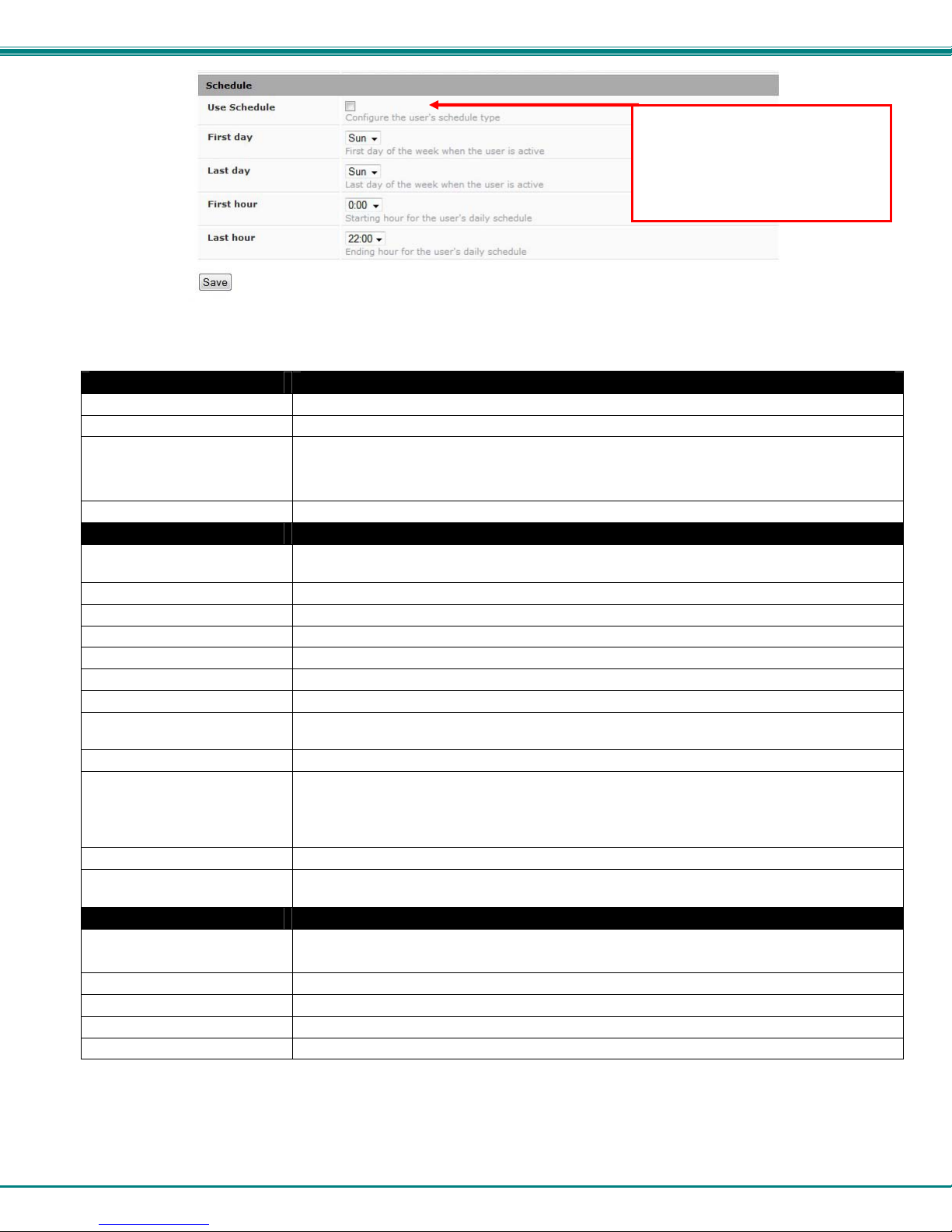
Schedule Settings
Schedule Type
Without Checkmark- user will receive messages at all hours of each day
With Checkmark- user will only receive alert messages during times as outlined below
Start Day First day of the week the user should begin receiving messages
Last Day Last day of the week the user should receive messages
First Hour First hour of the day the user should begin receiving messages
Last Hour Last hour of the day the user should receive messages
Note: If “Use Schedule” is
checked, and the “Test Email”
button is clicked (page 27), Users
who are not scheduled to be active
at the time of the “test” will not
receive a test email.
More about User Privileges
The root user (or any user with administrator rights) can change the root password and configure how the root user will receive
alert messages. Users with administrative rights can change all configuration settings except for the root user name.
Users with user rights can see the current readings of monitored items, change their own passwords, configure alerts, configure
the Smart Alert, and view Data and Event Logs.
30
Page 36
NTI Micro Environment Monitoring System
IP Cameras
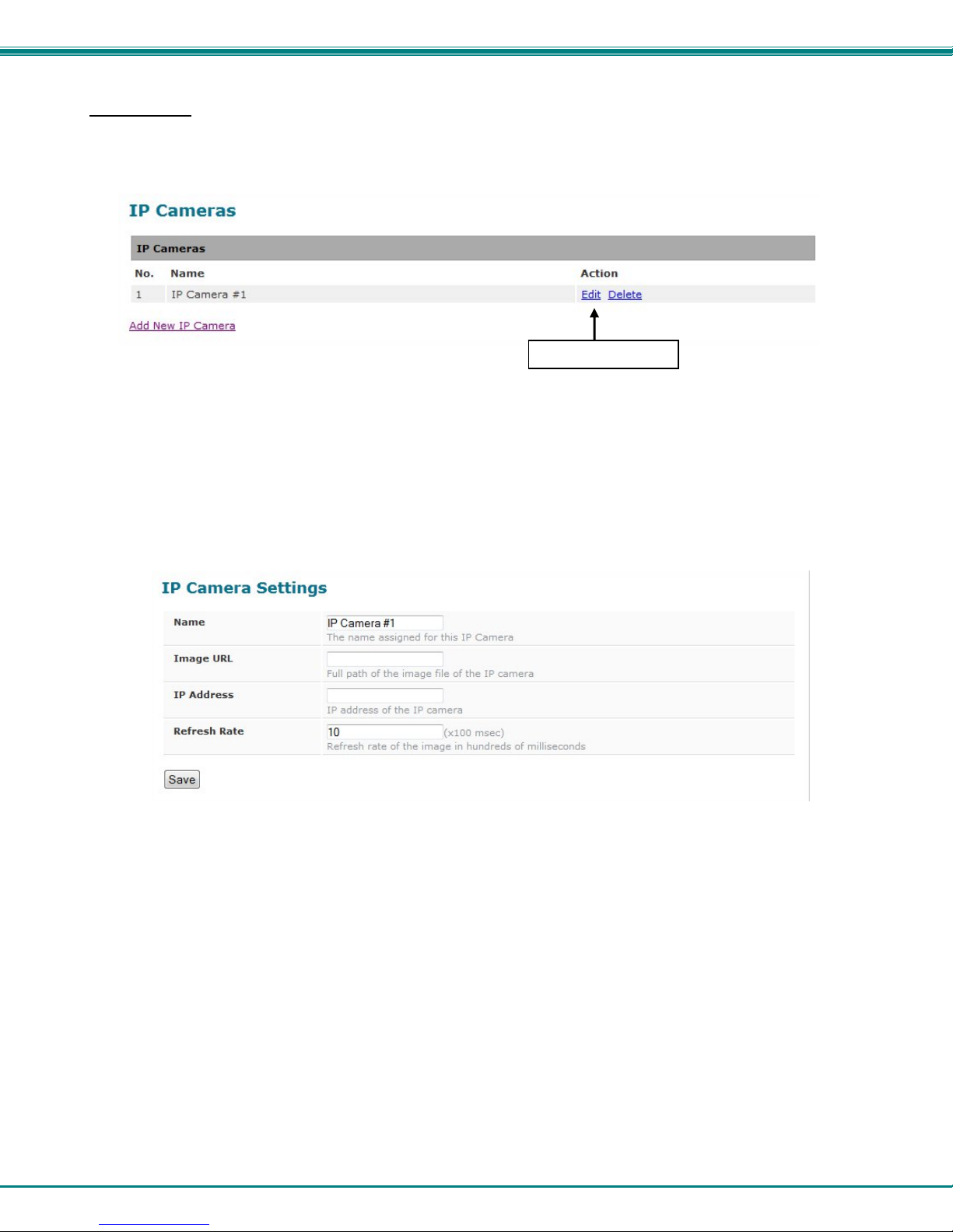
Up to 4 IP Cameras can be monitored by the ENVIROMUX. The ENVIROMUX will display the video from specified IP addresses
and provide images at 320 x 240 resolution. To see a list of IP cameras on the “IP Cameras” link in the side menu.
Figure 32- IP Camera Monitoring
To add an IP Camera, click on “Add New IP Camera.
Click to configure
Figure 33- Configure IP Cameras
Place a name, the URL or IP address of the link, and the full path including name of the image taken by the camera in the blocks
provided and click SAVE at the bottom of the page. Then click on Summary to see the images taken by those cameras. The
images can be set to be refreshed every 100 msec (.1 second) up to 99,900 msec (almost 100 seconds). The user can click on
any image and be connected to the site defined by the URL or IP Address.
31
Page 37
NTI Micro Environment Monitoring System
Update Firmware
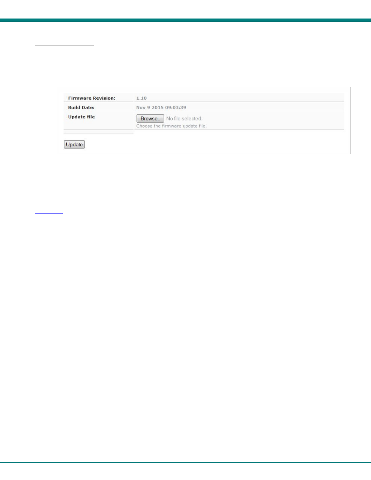
The Update Firmware page is used to change the firmware of the ENVIROMUX. Occasionally new features or changes to
existing features will be introduced and new firmware with these changes will be made available on the NTI website
(http://www.networktechinc.com/download/d-environment-monitor-micro.html
Firmware Update in the Administration section of the main menu. Once a user has downloaded the required file for firmware
upgrade, this page will be used to upload it to the ENVIROMUX.
Figure 34- Update Firmware page
1. Download the most current firmware file from http://www.networktechinc.com/download/d-environment-monitor-
micro.html to a location on your PC.
2. Click on the “Browse” button and locate and select the firmware file for the ENVIROMUX (enviromux-micro-vx-x.bin,
for example).
3. Click on the “Update” button to perform the firmware update. The firmware update process will take approximately 5 minutes
while the ENVIROMUX installs the firmware. Once the update file has been installed, the unit will automatically
reboot and the login screen will appear.
). To view the Update Firmware page, select
32
Page 38
NTI Micro Environment Monitoring System
Log
From the Log section there are three sub sections for configuring the ENVIROMUX:
View Event Log
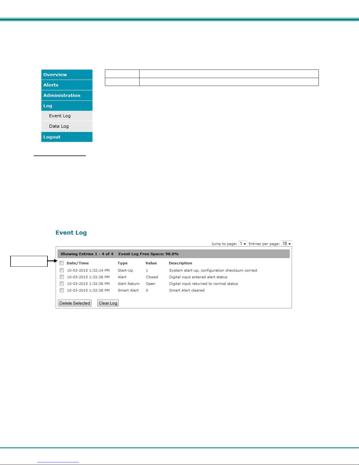
The Event Log provides the administrative user with a listing of many events that occur within the ENVIROMUX. The event
log will record the date and time of:
Select all
Event Log View a log listing the date and time of startups and alerts
Data Log View graph of data readings from sensors and IP addresses
• each ENVIROMUX startup,
• each user login and logout time,
• any time an unknown user tries to login,
• sensor and IP device alerts
• an alert handled by a user
Figure 35- Event Log page
From the Event Log page the administrative user can view the logs, select specific logs to be deleted or press Clear Log to delete
them all. The number of entries per page can be changed for the user’s reading preference. Navigating between pages is as
easy as clicking Previous or Next buttons, or jumping to a specific page if you know where the log entry you are interested in is
listed.
To clear only specific log entries, place a checkmark in each line item to be deleted, and press Delete Selected. To select all
entries at once, place a checkmark in the uppermost box.
33
Page 39
NTI Micro Environment Monitoring System
View Data Log
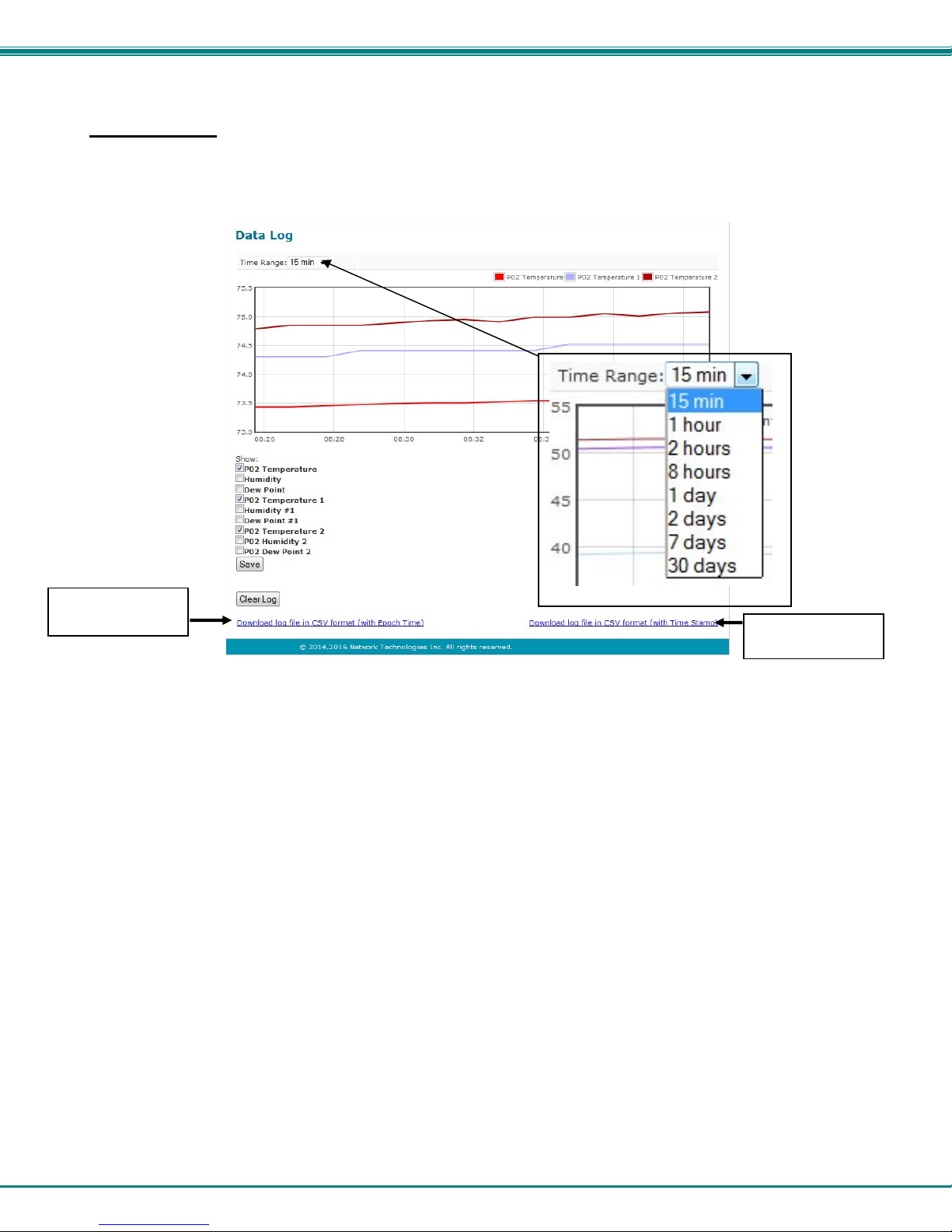
The Data Log provides the administrative user with a graphical representation of all the analog sensor readings (no digital
sensors) taken by the ENVIROMUX pertaining to the sensors being monitored. The event log will record the date and time of
each reading and display those readings in a chart. Additionally, readings taken from digital sensors can be found in the log file if
downloaded to a PC.
download file in
epoch time format
Figure 36- Data Log page
From the Data Log page the administrative user can view the logs, select specific logs to not be shown or press Clear Log to
clear them all. The time range of readings shown can be changed for the user’s viewing preference, from as little as15 minutes
up to 30 days.
To hide specific log entries, remove the checkmark for each sensor to be hidden, and press Save. Before clearing the log, the
user may want to save the log for future reference and to make space for more logs by downloading the data log to a file on a PC.
Click on “Download log file in CSV format” to save the log file before clearing it. The log file can be saved with either an Epoch
time format or in a standard date/time format.
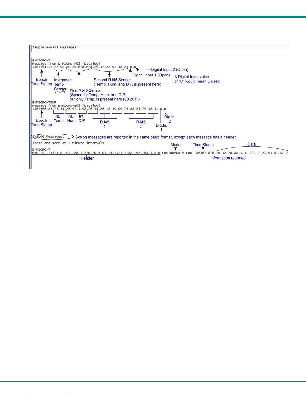
Data logs that are sent via syslog and/or email (page 29) will be in CSV format and will include data for all sensor ports whether
they are in use or not. (See examples on next page.) If an External Sensor port is not in use, the data log will include the entry
“N/A”. A Digital Input sensor port not in use will be reported as “Open”.
download file in
date/time format
34
Page 40
NTI Micro Environment Monitoring System
Figure 37- Examples of emailed datalogs
35
Page 41
NTI Micro Environment Monitoring System
IP Devices
IP devices such as servers, routers, cameras, etc. can be monitored (up to 4) to make sure network connections are open to
them. In order to monitor an IP Device the devices must be added to the list of IP Devices being monitored. From the Monitoring
page,
click on Add New IP Device.
Figure 38- IP Devices listing-none monitored yet
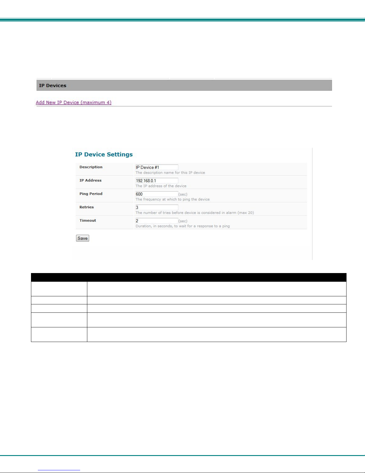
The IP Device Configuration page will immediately open. Here you can configure the ENVIROMUX to ping the IP Device (up to
4) as often as desired and to react to a lack of response by sending alert messages.
Figure 39- IP Device Configuration page
IP Device Settings Description
Description The description of the IP Device that will be viewed in the Summary page and in the body of alert
messages
IP Address The IP address of the IP Device
Ping Period Enter the frequency in seconds that the ENVIROMUX should ping the IP Device (range is 10 to 60000)
Retries Enter the number of times the ENVIROMUX should ping a non-responsive IP device before changing its
status from normal to alarm and sending an alert. Range is Min = 0, Max = 20
Timeout Enter the length of time in seconds (up to 10) to wait for a response to a ping before considering the
attempt a failure
As an example, let’s assume the three configurable values are set as follows:
Ping Period = 10 sec Timeout = 2 sec Retries = 5
The device being monitored will be pinged every 10 seconds and it should respond within 2 seconds.
If the device fails to respond within the 2 second timeout, the retry will occur immediately and wait two more seconds. This will
repeat for as many retries as you have configured. In this case, 5 tries. With 5 failures, the status will change to alert.
36
Page 42
NTI Micro Environment Monitoring System
The alert settings and data logging are the same as for sensor configuration, described on page 17.
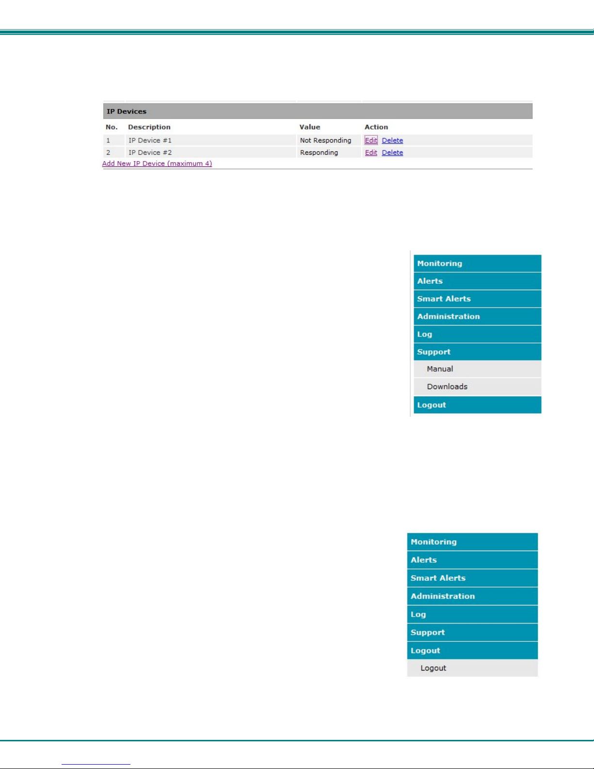
With a couple of IP devices having been configured for monitoring, the IP Device list will provide links editing their configuration or
deleting them from the list.
Figure 40- IP Device list with new devices added
Support
The Support section of the menu includes two links, Manual and Downloads.
The Manual link will open the pdf manual for the ENVIROMUX on the NTI website.
You must have Adobe Reader installed on your PC to open this.
The Downloads link will take you to the Firmware Downloads page for the ENVIROMUX
on the NTI website. All versions of firmware and MIB files for the ENVIROMUX will be
found there, available for immediate download to your PC.
Figure 41- Support
Logout
To logout of the ENVIROMUX user interface, click on the “Logout” section in the menu.
A gray menu label will drop down. Click on the gray label to be immediately logged
out. The login screen will appear, at which point you can close your browser or log
back in.
Figure 42- Logout
37
Page 43
NTI Micro Environment Monitoring System
OPERATION VIA TEXT MENU- ENVIROMUX
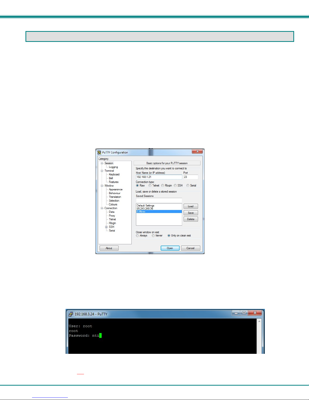
The ENVIROMUX can be controlled through a text menu using the Telnet provided a connection has bee n made to the Ethernet
Port (page 7). The text menu can be used to view sensor data, sensor alert status, and network settings of the ENVIROMUX as
an alternative to the Web Interface (page 13).
Note: Some terminal programs must be configured to use the Raw protocol instead of Telnet (i.e. Putty) due to extra
features used by the program that aren’t supported by the ENVIROMUX. In either case, be sure to configure the
terminal program to use port 23.
Note: Only one user can connect to the Text Menu at a time.
Connect to ENVIROMUX from Terminal through Ethernet
The Text Menu can be accessed using a Terminal program such as HyperTerminal, T era T erm, Putty, etc.. provided th e
ENVIROMUX is properly connected to your LAN through the Ethernet port (page 7).
1. Enter the IP address of the ENVIROMUX,
2. Select the Telnet connection type (you may have to use Raw, depending upon your program features),
3. Make sure the port number assigned is “23”.
Figure 43- Terminal connection through Ethernet port
4. Make sure the ENVIROMUX is powered ON.
5. Press <Open> and a login prompt will appear- “micro login:” , type <
<Enter>.
6. At “User: “ type <root> (all lowercase letters) and press <Enter>.
7. At “Password” type <
nti> (all lowercase letters) and press <Enter>.
Figure 44- Text Menu Login screen
Note: User names and passwords are case sensitive. It is important to know what characters must be capitalized and
what characters must not
.
root> (all lowercase letters) and press
38
Page 44
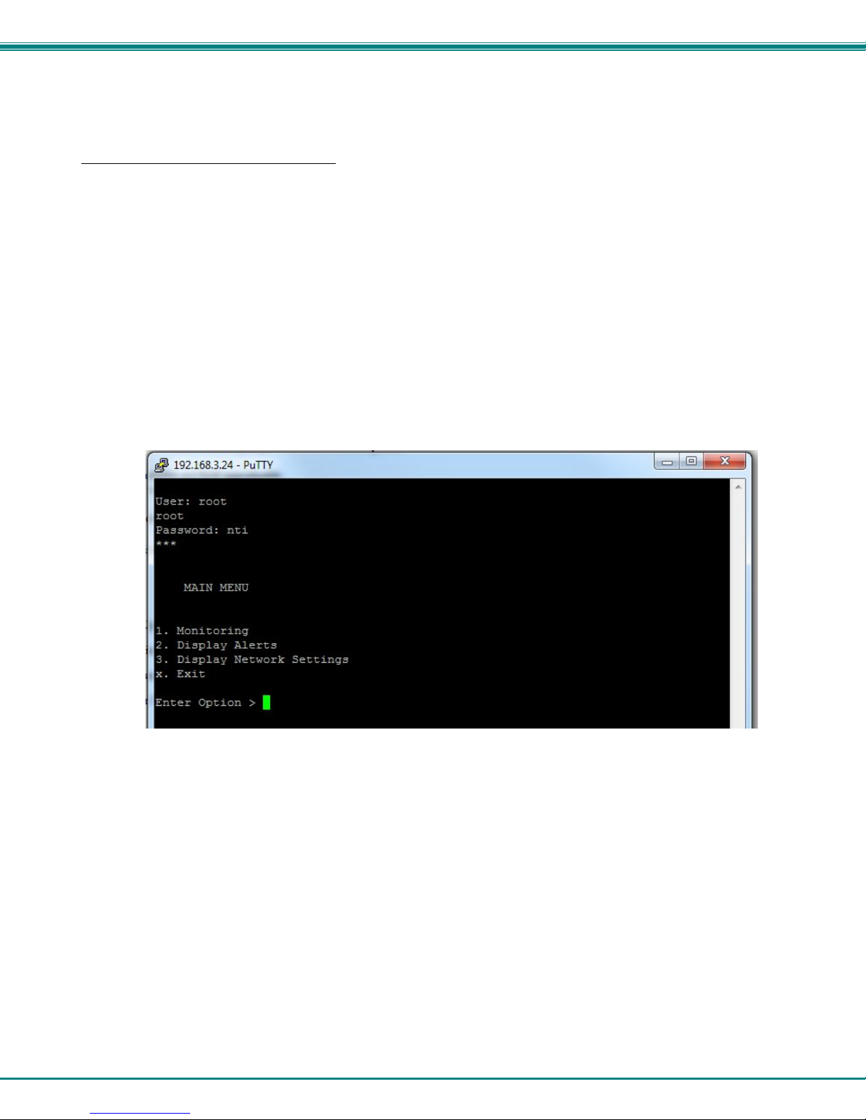
NTI Micro Environment Monitoring System
Connect to ENVIROMUX from Command Line
To access the Text Menu from the command line, the ENVIROMUX must first be connected to the Ethernet (page 7).
To open a telnet session to the ENVIROMUX
telnet <ENVIROMUX IP address>
<ENVIROMUX IP address> is the IP address assigned by the DHCP server unless you have manually assigned one. (default is
192.168.1.24).
The user will be prompted for username and password to connect to the ENVIROMUX. The default user is
password is “nti”
The main menu of the Text Menu will be displayed.
, issue the following command from the command line:
“root” and
Figure 45- Text Menu- Administrator Main Menu
39
Page 45
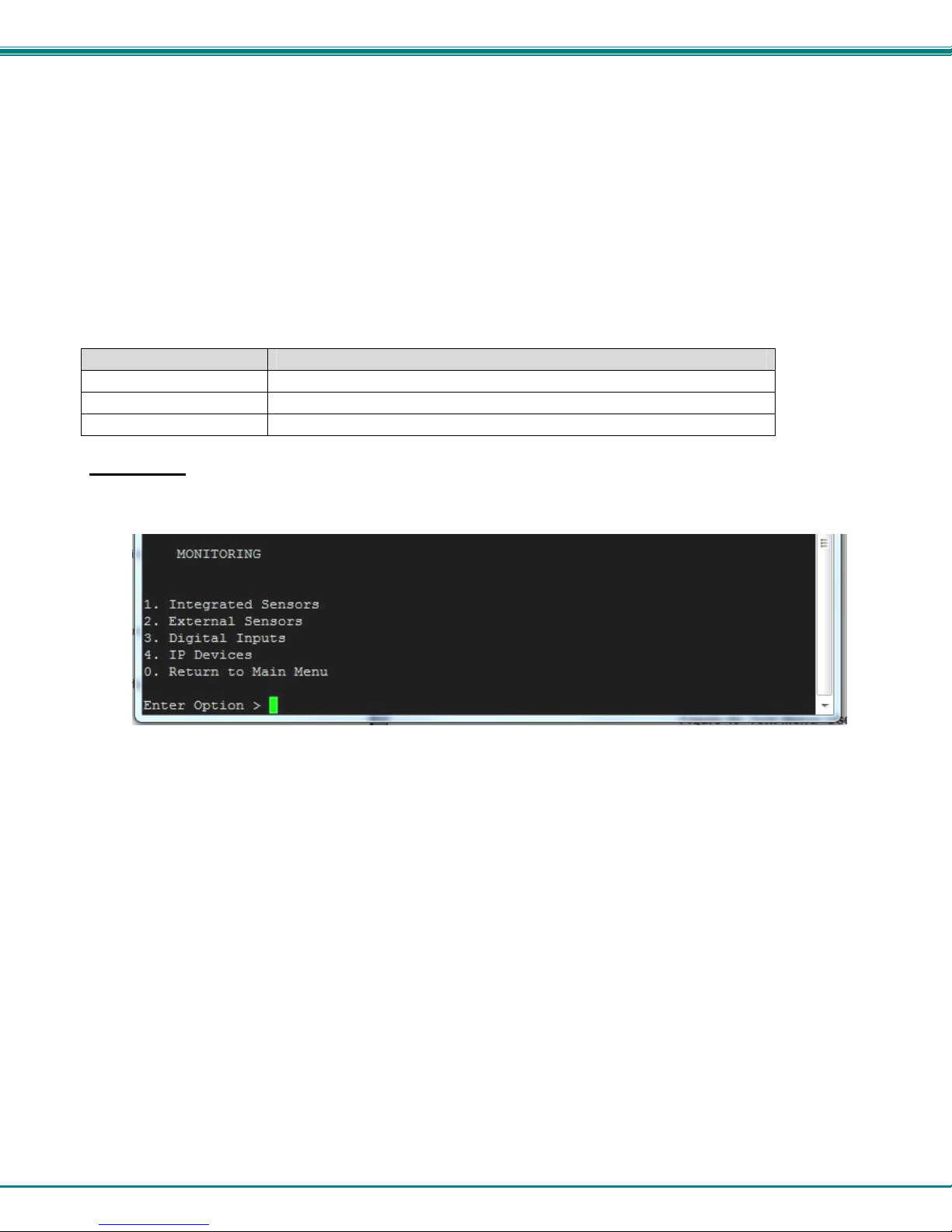
NTI Micro Environment Monitoring System
Using the Text Menu
Text Menu Navigation
For some terminal programs, just pressing the keyboard number associated with the menu item will select and execute that
choice. For other terminal programs, you will additionally need to press the <Enter> key after pressing the number.
Depending upon the terminal program you use, and its configuration, keys trokes entered may or may not be visible. For
example, when you enter <1> - <Enter> to select the Monitoring menu, you may see “1” appear next to “Enter Option” or you
may not.
When prompted to “Press any key to continue…..” press any key followed by <Enter> to return to the last menu.
The Main Menu is broken into 3 categories:
Function Description
Monitoring Monitor the sensors, digital inputs and IP devices
Display Alerts Show the status of any configured alerts
Display Network Settings Show the values of each of the network settings
Monitoring
The Monitoring menu lists choices for viewing the status of items monitored by the ENVIROMUX.
Figure 46- Text Menu-Monitoring Menu
40
Page 46
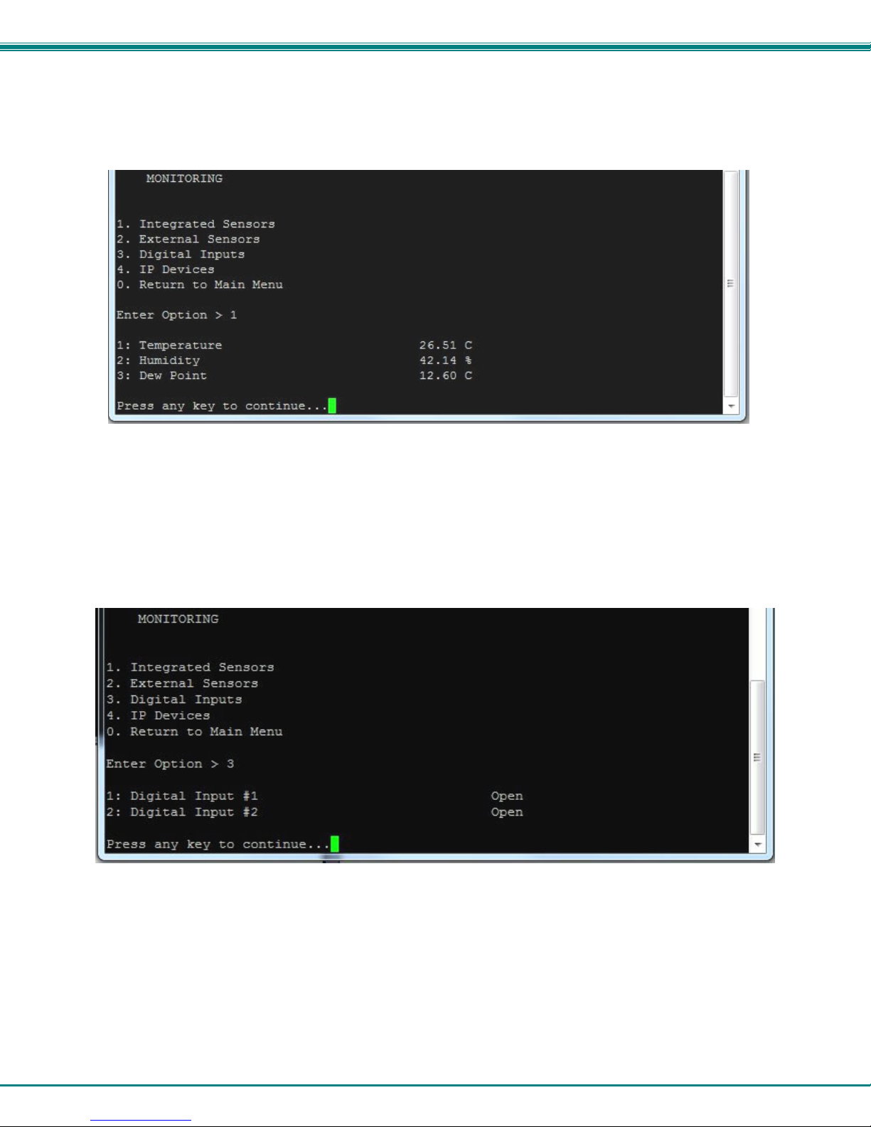
NTI Micro Environment Monitoring System
View Sensors
The Integrated or External Sensors selection will show the present status of each analog sensor connected to the ENVIROMUX.
Figure 47- Text Menu-Sensor Status
Digital Inputs
The Digital Inputs selection will show the present status of each dry contact sensor connected to the ENVIROMUX.
Figure 48- Text Menu- Digital Input Status
41
Page 47
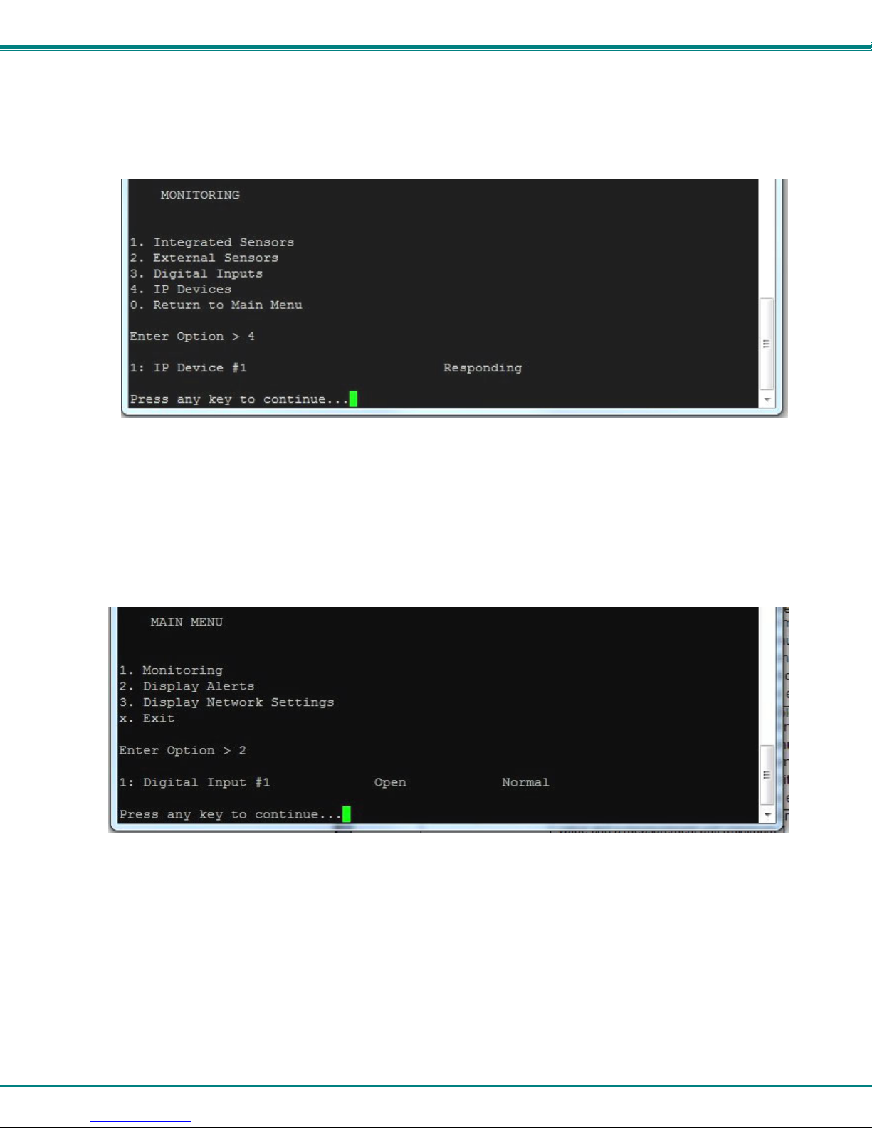
NTI Micro Environment Monitoring System
IP Devices
The IP Devices selection will show the present status of each IP Device monitored by the ENVIROMUX.
Figure 49- Text Menu-View IP Devices
Display Alerts
Select “Display Alerts” to see the current status of each alert. It will show the status of the sensor being monitored and it will
indicate if the sensor is in alert status or normal.
Figure 50- Text Menu-Configure Sensors list
42
Page 48
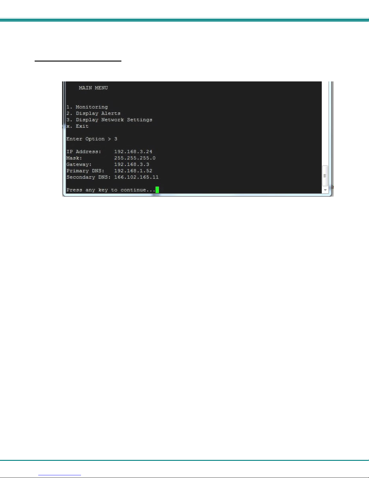
NTI Micro Environment Monitoring System
Display Network Settings
Select “Display Network Settings” to view the current Network configuration of the ENVIROMUX.
Figure 51- Text Menu-Network Settings
Press <x> to exit the text menu.
43
Page 49
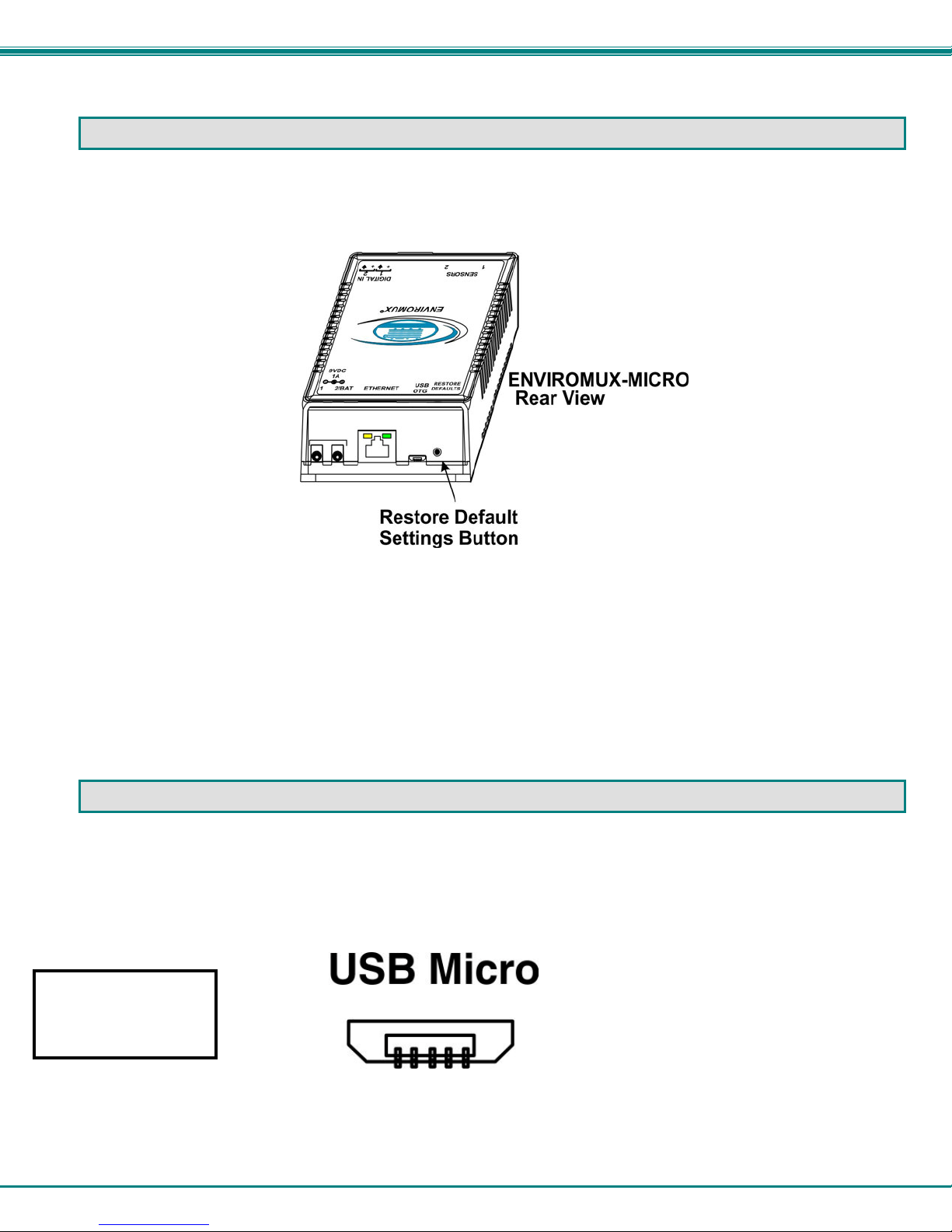
NTI Micro Environment Monitoring System
RESTORE DEFAULTS BUTTON
A “Restore Defaults” button is located on the front of the ENVIROMUX-MICRO-T(RHP). The button can be used to clear all
configuration changes and restore the ENVIROMUX to default settings including the administrative pa ssword. T o use this button,
press it with a pen or other small pointed object and hold it for 5 seconds. The ENVIROMUX will reboot and be ready for login
within its usual start-up time period.
Figure 52- Location of Restore Defaults button
Note: If “Restore Defaults” is used, the IP address will also be restored to its default address of 192.168.1.24 with a login
name “root” and password “nti”. To restore the root password to “nti” without having to restore all default settings,
contact NTI for assistance.
To identify the IP address of the ENVIROMUX without restoring defaults, use the Discovery Tool (page 12).
USB PORT
The ENVIROMUX is equipped with a “USB OTG” Micro USB female port for connection of a USB flashdrive (page Error!
Bookmark not defined.) or GSM modem (page 9) for receiving alert messages via SMS. When a modem is connected using the
adapter cable provided (page 9), it will automatically be sensed by the ENVIROMUX (page 24). The port is compatible with USB
2.0 Full Speed flash drives. When enabled and with the USB flash drive connected, the Data Logs will be written to a text file on
the flash drive in addition to the memory in the ENVIROMUX.
Connection of a USB
Flashdrive is not
supported as of this
printing.
Figure 53- USB OTG port
44
Page 50
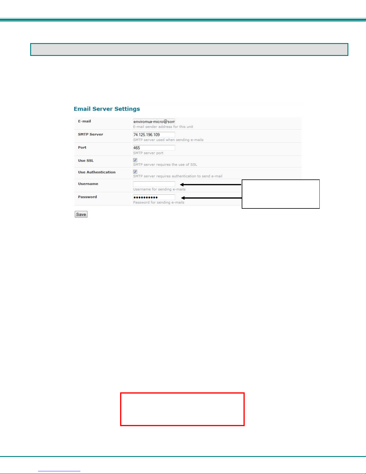
NTI Micro Environment Monitoring System
HOW TO SETUP EMAIL
Use this guide to assist in the configuration of the ENVIROMUX to send email messages.
1. Apply a valid email address for the ENVIROMUX to the Email Server Settings Page (see page 27).
Must fill in when
authentication is required
Figure 54- Email Server Settings example
Note: When authentication is required (check your email server requirements) the Username a nd Password must be
entered. If no authentication is required, the Username and Password fields can be left empty.
2. Fill in Email Settings (page 25) with valid information:
A. SMTP Server - check with your service provider as to what this should be.
Sometimes it is just the name of the provider (gmail.com), sometimes characters are added (mail.gmail.com,
smtp.gmail.com, smtp-mail.gmail.com, etc)
B. The default port is 25. If authentication is required, a different port number may be required. Check with
your service provider.
C. Check “Use SSL” if your SMTP server requires SSL.
D. Check “Use Authentication” if SMTP server requires authentication to send emails.
a. If required, Enter “Username” and “Password” that has been assigned to ENVIROMUX.
Example: [email protected] Most servers (not all, check with your service provider) use just the characters in front of
the “@” for your Username on the account. These, and only these characters should be entered into the “Username” block.
Note: Passwords are case sensitive. Be sure to apply the password exactly as it is required by the server.
When using Gmail for the ENVIROMUXMICRO, be sure to turn ON the feature
“Enable less secure apps” under the Gmail
security settings
45
Page 51
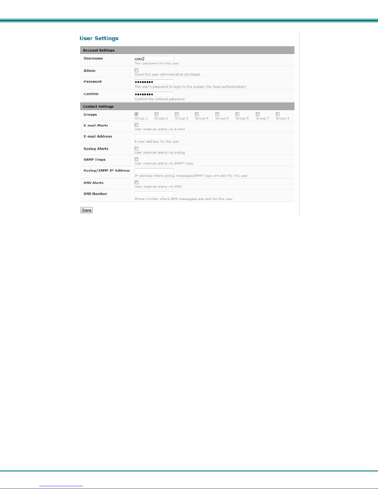
NTI Micro Environment Monitoring System
Figure 55- Configure user to receive alerts via email
3. Verify the User is configured to receive notifications for at least one sensor group as well as having “E-Mail Alerts”
selected and a valid E-Mail address to send the notifications to.
46
Page 52
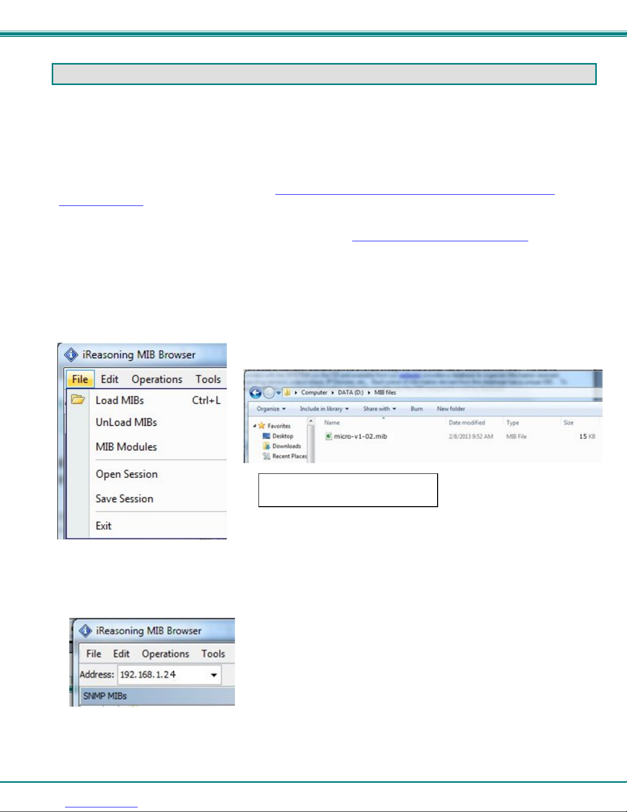
NTI Micro Environment Monitoring System
LOCATING OIDS
To use SNMP (Simple Network Management Protocol) to monitor the sensors and control the functions of an ENVIROMUX Micro
Environment Monitoring System (SYSTEM), you first need to install SNMP network management software. The software
package will include an MIB (Management Information Base) browser and there are many different MIB browsers so we will be
very general about the instruction provided herein. The MIB browser can be used to quickly view sensor data and the status of
all characteristics of the SYSTEM. How you make use of that information is up to you.
General Information
Every piece of information available from the SYSTEM through the MIB browser has an OID (Object Identifier). The MIB file
provided with the SYSTEM (on the CD and available from http://www.networktechinc.com/download/d-environment-
monitor-micro.html) provides a database to organize information received regarding sensors, IP Devices, etc.. Each piece of
information derived from this database has a unique OID. To see the OID for any piece of information, select the variable and
the OID assigned to it will be displayed.
For this instruction we used the free MIB browser “iReasoning” found at http://ireasoning.com/mibbrowser.shtml
View OIDs
To view this information, you must do the following:
1. Install the browser to your PC
2. Copy the MIB file associated with your SYSTEM to the hard drive on your PC.(perhaps to a new directory “MIB files” as shown
below.)
3. Load the MIB file for the SYSTEM to your browser.
TIP: iReasoning provided a couple of default MIB files that were preloaded. To clean up the resulting data tree, we used
“UnLoad MIBs” (above) to remove those.
4. Enter the IP address of the SYSTEM so the browser knows where the SYSTEM is to retrieve data.
5. With the iReasoning browser, the Read-only Community Name (default is “public”) was automatically sensed and appli ed
when the IP address was entered, but if this doesn’t happen in your browser, make sure the “Read Community” field in the agent
properties includes the name “public” (or whatever you have changed it to in the ENVIROMUX-16D network configuration).
Select “Load MIBs” and locate the
MIB file on your PC.
.
47
Page 53
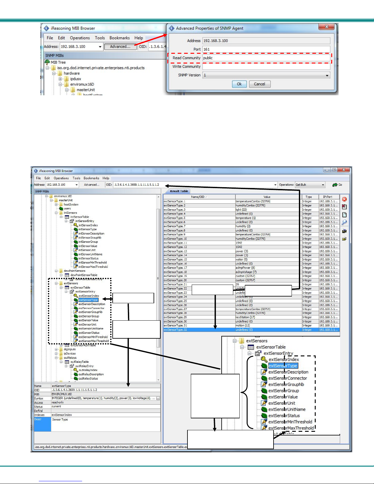
NTI Micro Environment Monitoring System
6. With that information entered, the default SYSTEM will be accessible for SNMP browsing.
A connection that uses security will require more configuration, Refer to page 26 and your browser manual to apply the required
additional settings.
Once a connection is made, the browser will present a directory structure with tree organizing all the different variables of
information available from the SYSTEM. Click on the various categories and sub categories to go as deep into the hierarchy as
necessary. As seen in the image below, each variable of information presented has an OID assigned to it. These OIDs can be
used in conjunction with other SNMP control systems to communicate and/or perform functions automatically.
View category
info here
View OID here
Each variable
has a value
that can be
identified with
an OID…
… and each variable for each
sensor has a separate OID.
48
Page 54
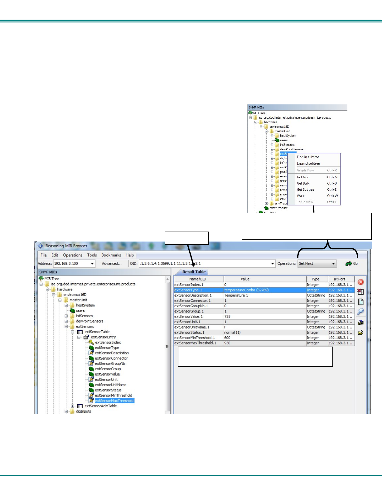
NTI Micro Environment Monitoring System
Each RJ45 Sensor port has two OIDs assigned, because the sensors that connect to these ports often have two possible
functions (Temperature/Humidity, ACLM-V with two connections, etc.). The image above shows they are numbered sequentially
(The “extSensor Type” variable for Port 1 is extSensorType.1 and extSensorType.2, port 2 is extSensorType.3 and
extSensorType.4, and so on, for a total of 4 extSensors (RJ45 Sensor) for an ENVIROMUX-MICRO.)
Each variable for a sensor that is reported has its own OID (i.e. Index number, type, description of the connected sensor, the
connector number the sensor is plugged into, group the sensor belongs to, etc.). When using OIDs, be sure to create an
association with the right variable.
To get specific results in the Result Table, right click on an item in the MIB Tree
and choose the type of search (“operation”) you want.
Get Next- will result in the next OID record of that category, displaying them one at
a time.
Get Bulk- will result in all the OIDs of that category being displayed at once, but only
that category
Get Subtree- will result in OIDs of that category and any sub-categories in the tree
Walk- will result in a listing of every OID in the system from the point at which you
select it until the last category in the tree.
Result Table
The value of each variable for the sensor can be listed
separately.
The operation can be selected with a right
click (above), or using the “Operations” field
(below). Once selected, press “Go”
49
Page 55
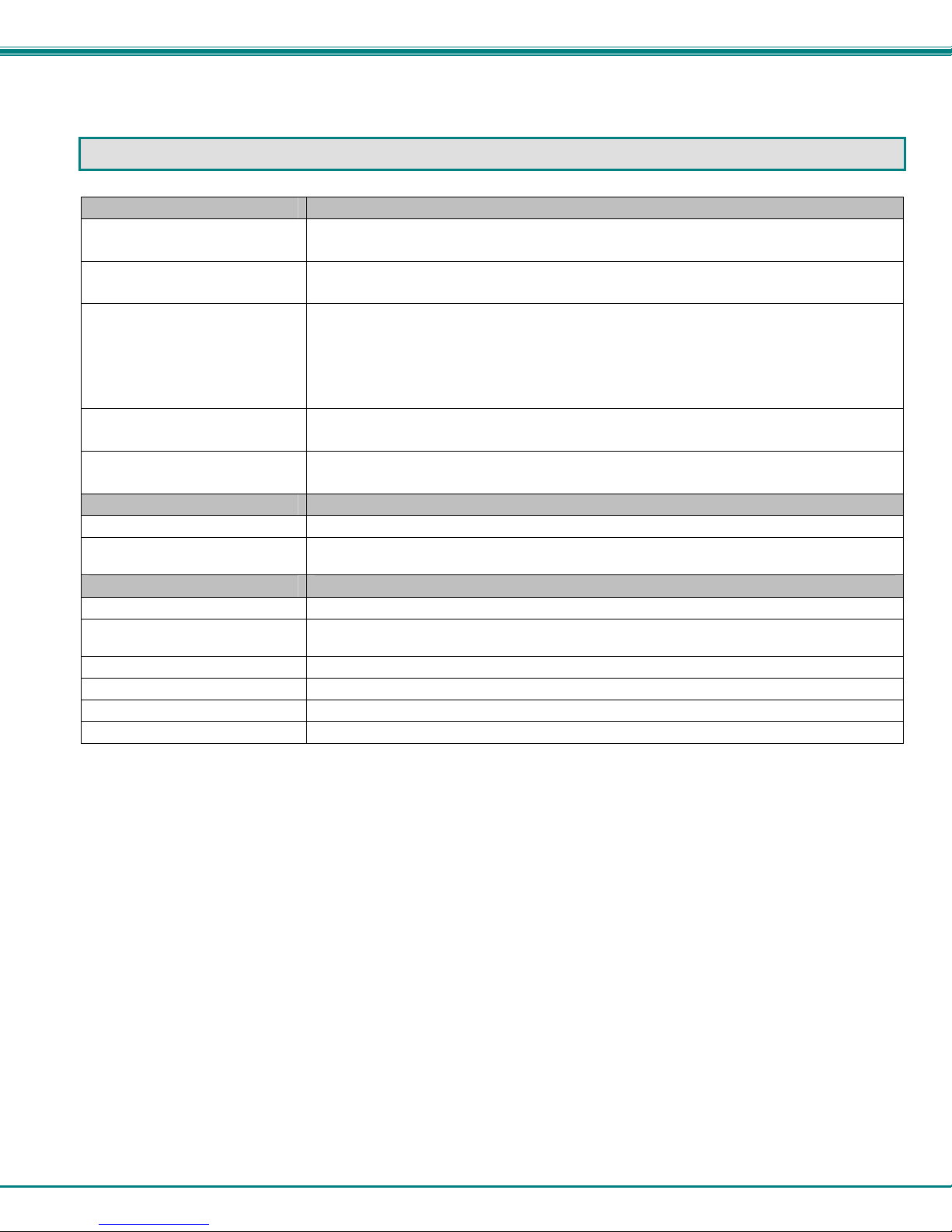
NTI Micro Environment Monitoring System
TECHNICAL SPECIFICATIONS
Ports
Sensor Inputs
Max. Sensor Cable Length
DIGITAL IN Dry Contact
Closures
Ethernet Port One female RJ45 connector with LEDs.
USB OTG Port Female Micro USB Type B connector
Environmental
Operating/Storage temperature
Operating and Storage Relative
Humidity
General
Compatible Modems ENVIROMUX-GSM-3GU (NetComm N3GS003)
Protocols
PoE Support IEEE 802.3af and 802.3at standards
Power Supply 120VAC or 240VAC at 50 or 60Hz-5.5VDC/1.5A AC Adapter
Dimensions WxDxH (in.) 4x3.437x1.37
Approvals RoHS
Two female RJ45 connectors for connecting temperature and/or temperature/humidity
sensors
Temperature Sensors- 507 feet
Liquid and Contact Sensors- 1000 feet
Two screw terminal pairs for connecting dry contact devices and liquid detection sensors.
* Potential-free.
* Output voltage: +5 V DC
* Current limited to 10 mA
* Maximum contact resistance: 10K Ohm
10 BaseT Ethernet interface.
Supports USB 2.0 Full Speed
-4°F to 185°F (-20°C to 85°C)
0 to 99% non-condensing RH
HTTP, HTTPS,SNMP, SMTP, TCP/IP, UDP, Xmodem, SSLv3, IP Filtering, AES 256-bit
encryption, SNMPv1,v2c
50
Page 56
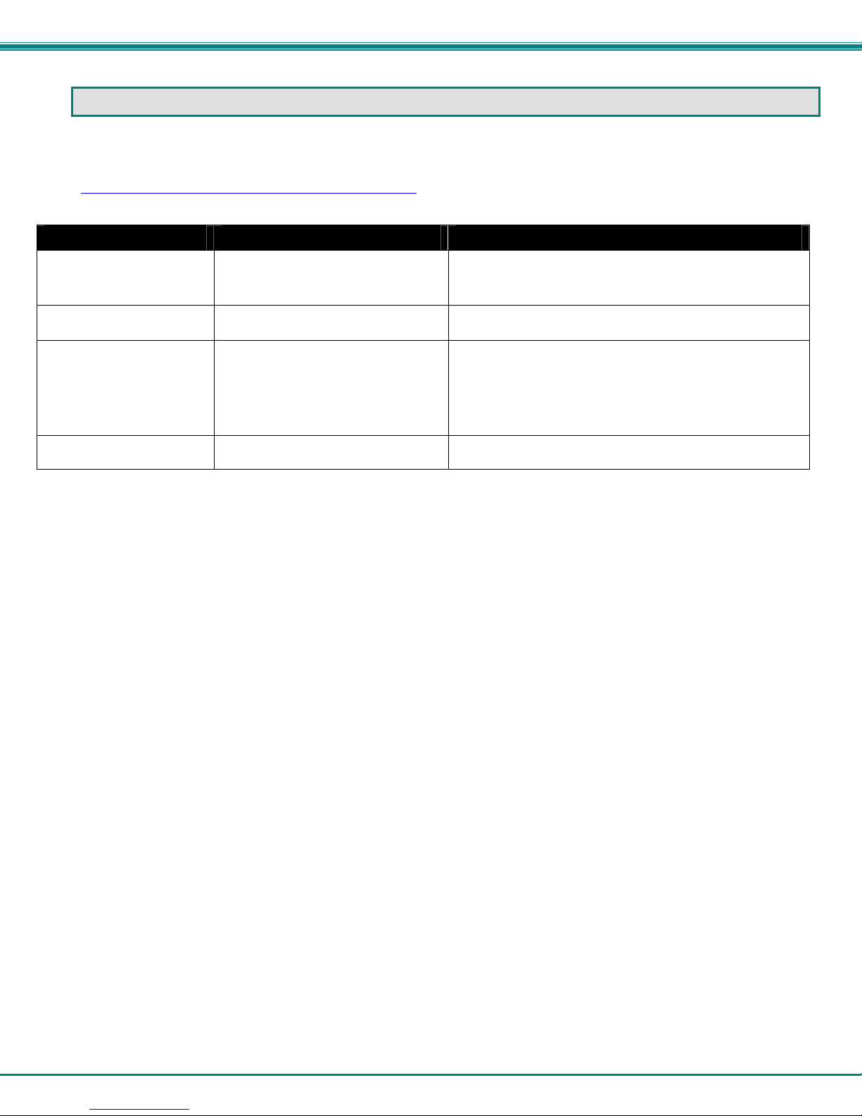
NTI Micro Environment Monitoring System
TROUBLESHOOTING
Each and every piece of every product produced by Network Technologies Inc is 100% tested to exacting specifications. W e
make every effort to insure trouble-free installation and operation of our products. If problems are experienced w hile installing this
product, please look over the troubleshooting chart below to see if perhaps we can answer any questions that arise. If the answer
is not found in the chart, a solution may be found in the knowledgebase on our website at
http://information.networktechinc.com/jive/kbindex.jspa
(330) 562-7070 and we will be happy to assist in any way we can.
Problem Cause Solution
Cannot connect via web
interface- no login
screen
Cannot get Discovery Tool
to work
Cannot connect via Telnet
Cannot login
wrong IP address Use Discovery Tool to locate configure IP address (page 12)
Java not installed Java Runtime Environment must be installed before the
• Ethernet cable not connected
• wrong IP address
• wrong port number
• telnet not supported via o perating
system
cannot remember root password Either restore default settings (page 44) or contact NTI for
or please call us directly at (800) 742-8324 (800-RGB-TECH) or
Discovery Tool can be used (page 12)
• check Ethernet cable connection
• Use Discovery Tool to locate IP address (page 12)
• Configure terminal to use port 23
• Use a terminal program instead of the command line
assistance
51
Page 57
NTI Micro Environment Monitoring System
INDEX
AC adapter, 8
acknowledge, 16
Administration, 24, 33
connect sensors, 4
data log-view, 34
default IP address, 13
Device Discovery Tool, 12
DHCP server, 25
dismiss, 16
downloads, 36
email setup, 44
Ethernet connection, 7
event log-view, 33
firmware update-web, 32
flash drive, 43
groups, 19
GSM modem, 9, 11
IP Cameras, 31
IP devices-configure, 35
IP devices-monitor, 35
Java Runtime Environment, 12
liquid detection sensor, 5
log in, 13
log to flashdrive, 34
login-web interface, 13
monitoring-web interface, 15
Network configuration, 42
Network Configuration, 25
overview, 10
Password, 13
reboot, 24
reset button, 43
sensors-configure, 41
setup email, 44
smart alerts, 20
SMTP server, 27
SNTP server, 28
Summary page, 14
system configuration, 24
Telnet, 38
text menu navigation, 39
threshold, 19
troubleshooting, 47
USB Flashdrive, 34
USB port, 43
username and password, 13
web browsers supported, 2
WARRANTY INFORMATION
The warranty period on this product (parts and labor) is two (2) years from the date of purchase. Please contact Network
Technologies Inc at (800) 742-8324 (800-RGB-TECH) or (330) 562-7070 or visit our website at http://www.networktechinc.com
for information regarding repairs and/or returns. A return authorization number is required for all repairs/returns.
MAN220 Rev. 6/1/16
52
 Loading...