

Page 1
E
NVIROMUX® Series
ENVIROMUX-PT3-600
Installation Guide
The ENVIROMUX-PT3-600 is a 3 phase AC voltage transducer that will monitor and report voltage of any 3 phase circuit when
connected to an ENVIROMUX-SEMS-16, ENVIROMUX-16D/5D/2D (SYSTEM) through one (for two phase monitoring) or two (for
3 phase monitoring) ENVIROMUX-S420MA-24V 4-20mA Sensor Converters.
Use the instructions provided for proper use and operation of the ENVIROMUX-PT3-600, but for installation follow the steps
outlined below.
Connect to ENVIROMUX-S420MA-24V
1. Mount the ENVIROMUX-PT3-600 as desired.
2. Before connecting the ENVIROMUX-PT3-600 to the 3 phase voltage source, connect it to the ENVIROMUX-S420MA24V. (The ENVIROMUX-S420MA should already be connected to the SYSTEM as outlined in the manual for the
ENVIROMUX-S420MA-24V). The ENVIROMUX-S420MA-24V has two sets of terminals for connection of up to two
channels from the ENVIROMUX-PT3-600 using 20-22AWG wiring.
3. Locate the “Current Sensor” that should now be listed in the Sensor Summary page of the SYSTEM web
interface. Two sensors will be listed, one for the ENVIROMUX-PT3-600 channel connected to ENVIROMUX-S420MA 24V terminal set 1, and another for the channel connected to terminal set 2. The reading in the “Value” column should be
“4mA” for each terminal set connected to a channel from the ENVIROMUX-PT3-600. (If the terminal set on the
ENVIROMUX-S420MA-24V is left empty, the value will be 0mA.)
If the value for the connected channel is not 4mA, follow the zero adjust procedure that follows.
Page 2
Zero Adjust
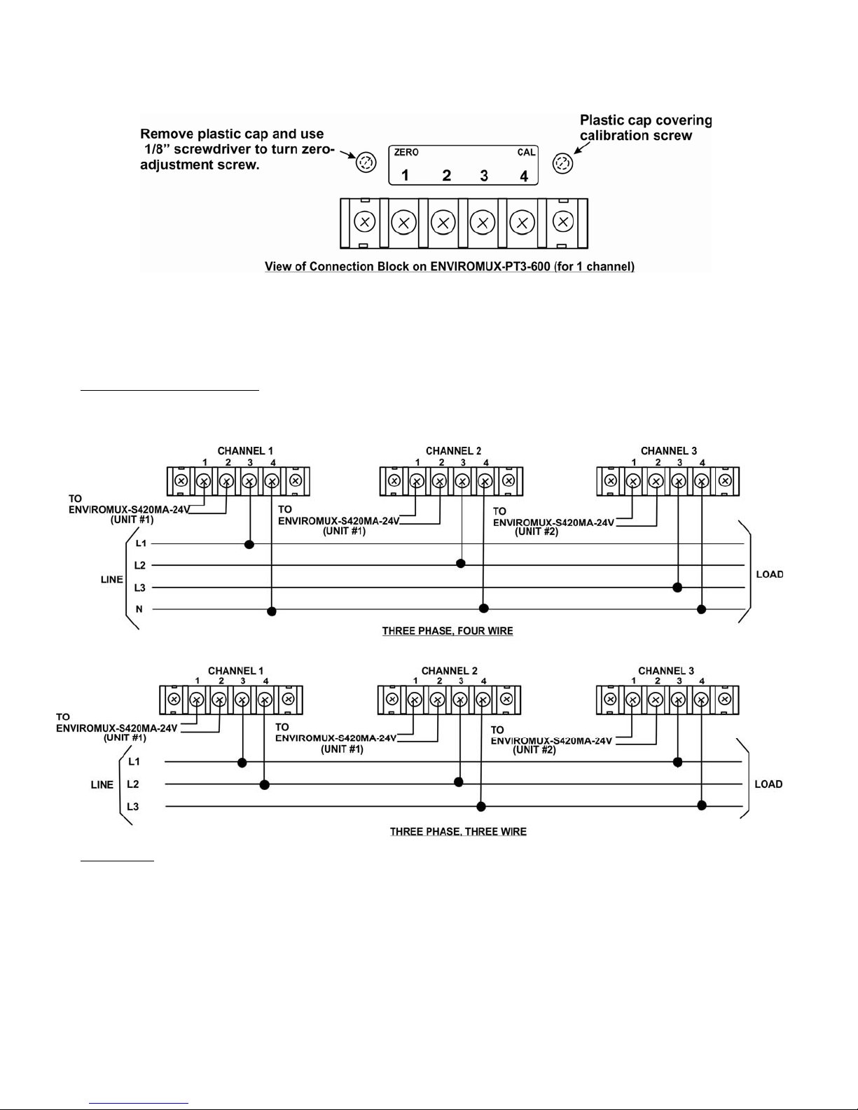
A. Remove the plastic cap covering the zero adjustment screw (see drawing below).
B. Rotate the zero adjustment screw using a 1/8” wide screwdriver until the reading on the sensor summary page is
“4mA”.
C. Replace the plastic cap.
Connect to 3 Phase Circuit
Make connections from the ENVIROMUX-PT3-600 to a 3 or 4 wire 3 phase circuit as indicated below.
Calibration
The ENVIROMUX-PT3-600 comes pre-calibrated from the factory. In the event re-calibration is required, follow these steps:
A. Perform the Zero Adjust procedure (above) first. Make sure there is no voltage at terminals 3 and 4 on the channel
B. Remove the plastic cap covering the calibration screw (see drawing at top of page).
C. Apply 600 VAC to terminals 3 and 4 of the channel blocks.
D. Rotate the calibration screw using a 1/8” wide screwdriver until the reading of the “Value” for the current sensors on the
Use the ENVIROMUX-PT3-600 as indicated in the supplied operating instructions.
blocks before performing the Zero Adjust procedure.
ENVIROMUX Summary Page is “20mA”.
MAN147 Rev. 5/14/15
 Loading...