

Page 1

V
(
y)
OPEX®Series
VOPEX-C5HDMI-4
HDMI Digital Video and Audio
Splitter/Extender via CAT6
Installation and Operation Manual
MAN118 Rev Date 11/6/2009
VOPEX-C5HDMI-4
Front and Rear View
ST-C5HDMI-150 Remote Unit
Front and Rear View
Sold Separatel
Page 2

TRADEMARK
VOPEX is a registered trademark of Network Technologies Inc in the U.S. and other countries.
COPYRIGHT
Copyright © 2009 by Network Technologies Inc. All rights reserved. No part of this publication may be reproduced, stored in a
retrieval system, or transmitted, in any form or by any means, electronic, mechanical, photocopying, recording, or otherwise,
without the prior written consent of Network Technologies Inc, 1275 Danner Drive, Aurora, Ohio 44202.
CHANGES
The material in this guide is for information only and is subject to change without notice. Network Technologies Inc reserves the
right to make changes in the product design without reservation and without notification to its users.
Note: CAT6 connection cable used between NTI VOPEX and XTENDEX Remote or any XTENDEX Series products should
not be run underground, outdoors or between buildings.
WARNING: Outdoor or underground runs of CAT6 cable could be dangerous and will void the warranty.
Page 3

TABLE OF CONTENTS
Introduction....................................................................................................................................................................... i
Materials..........................................................................................................................................................................1
Features and Functions...................................................................................................................................................2
Cable Connections..........................................................................................................................................................6
Daisy-Chaining................................................................................................................................................................8
Interconnection Cable Wiring Method.............................................................................................................................9
LED Indications ...............................................................................................................................................................9
Technical Specifications................................................................................................................................................10
Troubleshooting.............................................................................................................................................................11
Warranty Information.....................................................................................................................................................11
TABLE OF FIGURES
Figure 3- Connect the Remote to the VOPEX with CAT6 cable ........................................................................................................6
Figure 4- Connect AC adapter...........................................................................................................................................................6
Figure 2- Connect the remote unit to a display..................................................................................................................................7
Figure 1- Connect the VOPEX to a video source and local monitor ..................................................................................................7
Figure 5- Daisy-chained Remote Units..............................................................................................................................................8
Figure 6- View looking into RJ45 female............................................................................................................................................9
Page 4

INTRODUCTION
The VOPEX® HDMI Splitter/Extender simultaneously distributes digital video and audio signals from one video source to up to
four displays, each located up to 150 feet away using CAT6 solid UTP cable.
The VOPEX system consists of two components: the HDMI broadcast unit, which connects to the host video source and also
supplies video to a local display, and an XTENDEX remote unit for each remote display. The units are interconnected by CAT6
solid UTP cable.
• Broadcast real-time HDMI video to multiple display locations.
• Transmits an uncompressed HDMI signal over one CAT6 cable
• Supports HDTV resolutions up to 1080p and computer resolutions up to 1920x1200
• Compliant with HDMI 1.2 and HDCP 1.1 standards
• Easily expandable. Add remote units as you add monitors
• Inexpensive CAT6 cable replaces bulky video cables
• Supports embedded digital audio through HDMI compatible TVs or audio receivers
• Auto gain, auto skew, and auto EQ for plug-and-play setup and zero maintenance
• Ideal solution for digital signage applications
Optional:
Daisy-chain receivers allow you to extend one video source to multiple displays and to reach longer dist ances. T he daisy-chain
receivers are available in one-output daisy-chain and three-output daisy-chain options:
ST-C5HDMI-150- Single-output remote unit
ST-C5HDMI-RD-150- Single-output daisy-chain remote unit
ST-C5HDMI-RD3-150- 3-output daisy-chain remote unit
Features:
ST-C5HDMI-150 Remote Unit (Receiver)
• One female HDMI-A port for HDTV or computer display.
• One female RJ45 port for receiving high definition video/audio signals and DDC signal.
Optional ST-C5HDMI-RD-150 One-Output Daisy-Chain Remote Unit (Receiver)
• Enables a daisy chain of five receivers at 1080p / eight receivers at 1080i/720p.
• One female HDMI-A port for HDTV or computer display.
• One female RJ45 port for receiving high definition video/audio signals and DDC signal.
• One female RJ45 port for sending high definition video/audio signals and DDC signal.
• Only every third receiver in daisy-chain needs power supply.
Optional ST-C5HDMI-RD3-150 Three-Output Daisy-Chain Remote Unit (Receiver)
• Enables a daisy chain of five receivers at 1080p / eight receivers at 1080i/720p.
• Each receiver supports three displays for a total of fifteen displays at 1080p and 24 displays at 1080i.
• Three female HDMI-A ports for HDTVs or computer displays.
• One female RJ45 port for receiving high definition video/audio signals and DDC signal.
• One female RJ45 port for sending high definition video/audio signals and DDC signal.
• Only every third receiver in daisy-chain needs power supply.
i
Page 5
NTI VOPEX HDMI Splitter/Extender
MATERIALS
Materials supplied with this kit:
• NTI VOPEX-C5HDMI-4 Splitter
• 110-220VAC, 50 or 60Hz-12VDC/3A AC Adapter
• This manual
Materials Not supplied but REQUIRED:
• XTENDEX HDMI Remote(s)
• CAT6 Solid unshielded twisted pair (UTP) cable(s) terminated with RJ45 connectors wired straight thru- pin 1 to pin 1, etc.
(see page 9 for proper EIA/TIA 568 B wiring method) Stranded cable is not recommended for use.
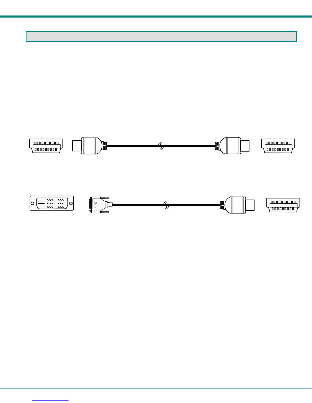
• A HDMI-xx-MM HDMI male-to-male cable for the video source and another for the display to be connected to the XTENDEX
Remote Unit. Cables are available from NTI where x= 3, 6, 14, 20, and 30 feet.
HDMI Type A
Male
Also available from NTI are DVI-HDMI-x-MM DVI-D Single link male to HDMI male cables (where x- 3, 6, 10, and 15 feet)
DVI-D-Male
Cables can be purchased from Network Technologies Inc by calling (800) 742-8324 (800-RGB-TECH) in the US and Cana da or
(330) 562-7070 (worldwide).
HDMI-A-Male
DVI-D-Male
HDMI-xx-MM
(3,6,14,20 an d 30 foot cables available)
DVI-HDMI-xx-MM
(3,6,10 and 15 f oot cables available)
HDMI-A-Male
HDMI-A-Male
HDMI Type A
Male
HDMI Type A
Male
1
Page 6

NTI VOPEX HDMI Splitter/Extender
FEA TURES AND FUNCTIONS
1. UTP1-4- RJ45 Females- for connecting CAT6 cables to go to XTENDEX Remote Units
1A. Communication LED- for indication that HDMI signals are being received
1B. Power LED- for indication that the connector is receiving power
2. 12VDC- for connection of AC adapter
3. HDMI IN- HDMI female connector- for connection to HDMI cable from video/audio source
4. HDMI OUT- HDMI female connector- for connection to HDMI cable from a display
1A
1B
UTP1 UTP2 UTP3 UTP4
Front View of VOPEX-C5HDMI-4
2
34
Rear View of VOPEX-C5HDMI-4
1
12VDC
-
Network Technologies Inc
NTI
R
VOPEX
R
HDMI
HDMI OUTHDMI IN
+
2
Page 7

NTI VOPEX HDMI Splitter/Extender
XTENDEX Remote Units
(Sold Separately)
1. HDMI OUT- HDMI female connector- for connection to HDMI cable from a display
2. UTP- RJ45 female connector- for connection of Unshielded Twisted Pair CAT6 cable between VOPEX and Remote Unit
3. Communication LED- for indication that HDMI signals are being received
4. Power LED- for indication that the Remote Unit is receiving power
Top View of ST-C5HDMI-150 Remote Unit
R
NTI
Network Technologies Inc
R
XTENDEX
Remote Unit
HDMI
1
HDMI OUT
Front View of ST-C5HDMI-150 Rem ote Unit
2
UTP
Rear View of ST-C5HDMI-150 Rem ot e Un it
3
4
3
Page 8

NTI VOPEX HDMI Splitter/Extender
HDMI-OUT1 HDMI-OUT3
5
5. 12VDC- Connector for attaching AC adapter
6. RJ45 In- RJ45 female connector- for connection of Unshielded Twisted Pair CAT6 cable from a VOPEX or an upstream
Remote Unit (Remote Unit closer in the daisy-chain to the Local Unit)
7. RJ45 Out- RJ45 female connector- for connection of Unshielded Twisted Pair CAT6 cable to a R emote Unit downstream in
the daisy-chain
8. AUX Port- RJ45 female connector- NOT SUPPORTED AS OF THIS PUBLICATION
Top View of ST-C5HDMI-RD3-150
1
HDMI-OUT2
Front View of ST-C5HDMI-RD3-150
UTP-IN
Rear View of ST-C5HDMI-R D3- 150
12VDC
-
Network Technologies Inc
NTI
R
XTENDEX
Remote Unit
R
HDMI
76
+
UTP-OUT
4
Page 9

NTI VOPEX HDMI Splitter/Extender
Top View of ST-C5HDMI-RD3-150
Network Technologies Inc
NTI
R
XTENDEX
Remote Unit
R
HDMI
1
HDMI-OUT1 HDMI-OUT3
Front View of ST-C5HDMI-RD3-150
HDMI-OUT2
5
76
UTP-IN
12VDC
-
Rear View of ST-C5HDMI-RD 3- 150
+
5
UTP-OUT
Page 10

NTI VOPEX HDMI Splitter/Extender
CABLE CONNECTIONS
1. Connect a CAT6 solid UTP cable (up to 150 feet) from a “UTPx” port on the VOPEX to the “UTP” port on the Remote Unit.
Connect up to 3 more remote units in the same fashion.
Front View of VOPEX-C5HDMI-4
UTP1 UTP2 UTP3 UTP4
CAT6 solid UTP cable
up to 150 feet
Rear View of ST-C5HDMI-150 R em ote Uni t
UTP
Figure 1- Connect the Remote to the VOPEX with CAT6 solid UTP cable
2. Connect the AC adapter to the VOPEX and plug it into an AC receptacle.
Rear View of VOPEX-C5HDMI-4
12VDC
Adapter
Adapter
-
12VDC
HDMI OUTHDMI IN
+
Figure 2- Connect AC adapter
6
Page 11

NTI VOPEX HDMI Splitter/Extender
3. Connect an HDMI-xx-MM cable between the “HDMI OUT” port on a Remote Unit and a display with an HDMI input.
Front View of ST-C5HDMI-150 Remote Unit
HDTV MONITOR
W/HDMI INPUT
HDMI OUT
HDMI-A-Male
(3,6,14,20 and 30 foot cables available)
HDMI-xx-MM
HDMI-A-Male
Figure 3- Connect the remote unit to a display
4. Connect an HDMI-xx-MM cable between the “HDMI IN” port on the VOPEX and an HDMI video source. Connect another
HDMI-xx-MM cable between the “HDMI OUT” port on the VOPEX and a display with an HDMI input (optional).
Cable Bo x
W/ HDMI
Output
HDMI Type A
Male
Local Monitor
(3,6,14,20 and 30 foot cables available)
HDTV MONITOR
W/HDMI INPUT
(3,6,14,20 and 30 foot cables available)
(using a local moni to r is optional)
Rear View of VOPEX-C5HDMI-4
HDMI-xx-MM
HDMI-xx-MM
HDMI-A-Male
HDMI-A-Male
-
12VDC
HDMI OUTHDMI IN
+
Figure 4- Connect the VOPEX to a video source and local monitor
5. Power ON the display first, then the video source.
7
Page 12

NTI VOPEX HDMI Splitter/Extender
DAISY-CHAINING
The VOPEX-C5HDMI-4 can be connect to up to 4 remote units, and those remote units can be single-monitor units such as STC5HDMI-RD3, single-monitor daisy-chain compatible units (ST-C5HDMI-RD-150), or 3-monitor daisy-chain compatible units (STC5HDMI-RD3-150.
The NTI ST-C5HDMI-RD-150 and ST-C5HDMI-RD3-150 can be daisy-chained in a config uration to include up to 5 remotes at
1080p / or up to eight remotes at 1080i/720p. The image below demonstrates a daisy-chain configuration with 3 remotes.
W/HDMI INPUT
W/HDMI INPU T
W/HDMI INPU T
Front View of VOPEX-C5HDMI-4
Front View of ST-C5HDMI-RD3-150
HDTV
MONITOR
HDTV
MONITOR
HDTV
MONITOR
HDTV
MONITOR
W/HDMI INPUT
HDMI-A-Male
MONITOR
W/HDMI INPUT
UTP1 UTP2 UTP3 UTP4
Remote Unit
HDMI-OUT1 HDMI-OUT3
HDMI-xx-MM
HDMI-xx-MM
HDMI-xx-MM
Rear View of ST-C5HDMI-RD-150
Remote Unit
HDMI-A-Male
HDTV
HDMI-xx-MM
Front View of ST-C5HDMI-150
Remote Unit
HDMI-A-Male
HDMI-xx-MM
HDMI-OUT2
HDMI OUT
HDMI-A-Male
CAT6 Cable
HDTV MONITOR
W/HDMI INPUT
HDMI-A-Male
HDMI-xx-MM
Rear View of ST-C5HDMI-RD3-150
Remote Unit
12VDC
UTP-IN
CAT6 Cable
+
-
Front View of ST-C5HDMI-RD-150
Remote Unit
12VDC
RJ45 In RJ45 Out
AUX Port
CAT6 Cable
+
-
Front View of ST-C5HDMI-150
Remote Unit
UTP
HDMI OUT
CAT6 Cable
Front View of
ST-C5HDMI-150
Remote Unit
HDMI OUT
HDMI-A-Male
UTP-OUT
Figure 5- Daisy-chained Remote Units
8
Page 13

NTI VOPEX HDMI Splitter/Extender
INTERCONNECTION CABLE WIRING METHOD
The connection cable between the remote and local is terminated with RJ45 connectors and must be wired according to the
EIA/TIA 568 B industry standard. Wiring is as per the table and drawing below.
1 White/Orange 2 T
2 Orange 2 R
3 White/Green 3 T
4 Blue 1 R
5 White/Blue 1 T
6 Green 3 R
7 White/Brown 4 T
8 Brown 4 R
Pin Wire Color Pair Function
Pair 2 Pair 1
T
1
+
Figure 6- View looking into RJ45 female
Pair 3
Pair 4
T
R
R
T
3
2
4
5
+
-
-
+
R
R
T
8
6
7
+
-
-
LED INDICATIONS
The two LED’s on the RJ45 connectors of the components in this manual have the following meaning:
VOPEX: All ports: Right = Power ON,
Left: Flashing = Waiting for receiver ready;
Solid = Receiver is attached to the port, EDID is validated, HDCP is active and working
ST-C5HDMI-150 Receiver: Right = Power ON,
Left = Receiving HDMI signals
ST-C5HDMI-RD-150 Receiver:
“RJ45-In” (Left): Left = Power ON,
Right: Flashing = Waiting for the display ready;
Solid= Display is attached, EDID is validated, HDCP is active and working.
“RJ45-Out” (Right): Left = Receiving the HDMI signal from transmitter;
Right: Flashing =Waiting for the downstream receiver on the UTP port ready;
Solid = downstream receiver is attached to the ST-C5HDMI-RD-150, EDID is validated,
HDCP is active and working
ST-C5HDMI-RD3-150 Receiver:
“RJ45-In” (Left): Left = Power ON,
Right: Flashing = Waiting for any display on the HDMI port ready;
Solid = At least one display is ready on the three HDMI ports, EDID is validated, HDCP is active and
working.
“RJ45-Out” (Right): Left = Receiving the HDMI signal from transmitter;
Right: Flashing =Waiting for the downstream receiver on the UTP port ready;
Solid = Downstream receiver is attached to the ST-C5HDMI-RD3-150, EDID is validated,
HDCP is active and working
9
Page 14

NTI VOPEX HDMI Splitter/Extender
TECHNICAL SPECIFICATIONS
Video bandwidth 4.8Gbps
Maximum Resolution 1080p/1920x1200 (Maximum distance- 150 feet)
HDMI Connector Type A 19-pin female
Link Connector RJ45 female
Signal Type HDMI 1.2, HDCP 1.1 compliant
Cable required CAT6 UTP solid 550 MHz or better cable with TIA/EIA-568B wiring terminated with standard RJ45
connectors is recommended for 1080p applications
Operating temperature 5°F to 122°F (-15°C to 50°C)
Storage Temperature 40°F to 185°F (-40°C to 85°C)
Storage Humidity 0% RH to 80% RH, non condensing
Operating Humidity 0% RH to 90% RH, non condensing
Power Supply
Size (In.) WxDxH
VOPEX
ST-C5HDMI-150
ST-C5HDMI-RD-150
ST-C5HDMI-RD3-150
Approvals RoHS, CE, FCC
110 or 220 VAC at 50 or 60 Hz-12VDC\ 3A via AC adapter (included).
Remote unit: powered from VOPEX via CAT6 solid UTP cable.
5x4.7x1.4
2.5x2.8x0.9 (local and remote unit)
3.9x3.2x1.4
5x4.7x1.4
10
Page 15

NTI VOPEX HDMI Splitter/Extender
TROUBLESHOOTING
Each and every piece of every product sold by Network Technologies Inc is 100% tested to exacting specifications. We make
every effort to insure trouble-free installation and operation of our products. If problems are experienced while installing this
product, please look over the information below to see if it can answer any questions that arise. If the answer is not found,
please contact us directly for help at 1-800-742-8324 (800-RGB-TECH) in US & Canada or 1-330-562-7070 worldwid e. We will
be happy to assist in any way we can.
Problem Cause Solution
No Video
Picture blanks out
sometimes
• Video Cable not connect properly
• No Power
• Monitor connected after video
source was powered-ON
Loss of sync between source and
display
• Check all cable connections
• Check power supplies. Power LEDs should be
illuminated
• Power-cycle video source
Try lowering resolution setting. If this helps, the CAT
cables being used are insufficient for the resolution
setting. Maximum resolution is 1080p/1920x1200 at 150
feet.
WARRANTY INFORMATION
The warranty period on this product (parts and labor) is two (2) years from the date of purchase. Please contact Network
Technologies Inc at (800) 742-8324 (800-RGB-TECH) or (330) 562-7070 or visit our website at http://www.networktechinc.com
for information regarding repairs and/or returns. A return authorization number is required for all repairs/returns.
PRODUCT: VOPEX-C5HDMI-4
SERIAL NO.:
DATE:
MAN118 Rev. 11/6/09
INSPECTED BY:
11
 Loading...