

Page 1
UNIMUX
TM
Series
UNIMUX-USBV-xO
USB KVM Switch
Installation and Operation Manual
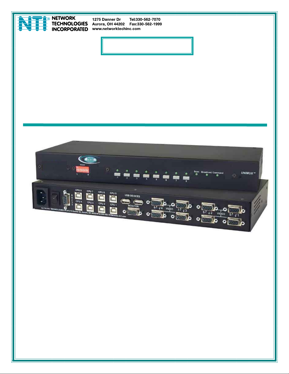
UNIMUX-USBV-8O-RS (Front and Rear View)
MAN035 Rev Date 2/12/2013
Page 2

TRADEMARK
UNIMUX is a trademark of Network Technologies Inc in the U.S. and other countries
COPYRIGHT
Copyright © 2000, 2013 by Network Technologies Inc. All rights reserved. No part of this publication may be reproduced, stored
in a retrieval system, or transmitted, in any form or by any means, electronic, mechanical, photocopying, recording, or otherwise,
without the prior written consent of Network Technologies Inc, 1275 Danner Drive, Aurora, Ohio 44202.
CHANGES
The material in this guide is for information only and is subject to change without notice. Network Technologies Inc reserves the
right to make changes in the product design without reservation and without notification to its users.
Application Note: This manual applies to UNIMUX-USBV-xO switches made on or after October 1, 2004.
.
Typographic Conventions
The table below offers examples of text format and its meaning when that format is used in place of the standard font (Helvetica)
used throughout this manual.
Typeface meaning Font Configuration Example
On-screen computer output Courier New-(not bold)
What you type on the computer Courier New-bold
C:>
C:>edit text.bat
i
Page 3

TABLE OF CONTENTS
INTRODUCTION.............................................................................................................................................................1
MATERIALS....................................................................................................................................................................2
DEFINITIONS..................................................................................................................................................................2
FEATURES AND FUNCTIONS.......................................................................................................................................3
RACKMOUNTING INSTRUCTIONS...............................................................................................................................4
To Mount to a Rack .....................................................................................................................................................4
INSTALLATION...............................................................................................................................................................5
Power-Up Sequence....................................................................................................................................................7
Limitations....................................................................................................................................................................7
USING THE UNIMUX USB KVM SWITCH.....................................................................................................................8
Front Panel Control......................................................................................................................................................8
Keyboard Control.........................................................................................................................................................8
MODES OF OPERATION...............................................................................................................................................9
Basic Command Mode ................................................................................................................................................9
Scan Mode................................................................................................................................................................9
Broadcast Mode......................................................................................................................................................10
Normal Mode ..........................................................................................................................................................10
No SUN Sleep Mode ..............................................................................................................................................10
Select Country Code...............................................................................................................................................10
Mice and Trackballs with MACs..............................................................................................................................11
OSD CONTROL............................................................................................................................................................12
Security Option..........................................................................................................................................................12
Enabling the Security Feature ................................................................................................................................12
User Login Mode.....................................................................................................................................................13
ADDITIONAL MODES AVAILABLE WITH SECURITY ................................................................................................14
Administration Mode...............................................................................................................................................14
Administrator Password..........................................................................................................................................14
User Name List.......................................................................................................................................................15
Edit User.................................................................................................................................................................15
Alternate Command Hot Key..................................................................................................................................16
Usage Statistics......................................................................................................................................................17
USER ACCESS FUNCTIONS.......................................................................................................................................18
OSD Command Mode ............................................................................................................................................18
Broadcast Mode......................................................................................................................................................19
Scan Mode..............................................................................................................................................................19
Normal Mode ..........................................................................................................................................................20
Edit Mode................................................................................................................................................................20
Change Settings .....................................................................................................................................................21
Select Ports For Broadcast.....................................................................................................................................21
Select Ports For Scan.............................................................................................................................................22
Language Selection................................................................................................................................................22
MAC Ports Configuration........................................................................................................................................22
Search Mode...........................................................................................................................................................23
Maintenance Mode.................................................................................................................................................24
Help Mode...............................................................................................................................................................25
F3- Display Information...........................................................................................................................................25
RS232 CONTROL.........................................................................................................................................................26
RS232 Connections and Configuration.....................................................................................................................26
Remote Connection................................................................................................................................................26
Baud Rate...............................................................................................................................................................26
Unit Address and Loop Back..................................................................................................................................27
Command Protocol.................................................................................................................................................27
NTI Switch Control Program For Windows 9X, NT, 2000, Vista and 7.....................................................................29
SerTest- RS232 Interface Test Program...................................................................................................................29
Main Options...........................................................................................................................................................29
MOUSE CLICK EQUIVALENTS ...................................................................................................................................31
KEYBOARD FEATURES..............................................................................................................................................31
ii
Page 4

Keyboard-To-Computer Translation..........................................................................................................................31
Translation Capabilities ..........................................................................................................................................31
Translation Tables ..................................................................................................................................................31
International Sun Keyboards.....................................................................................................................................32
CASCADING.................................................................................................................................................................33
Configuration .............................................................................................................................................................33
Cascaded Installation ................................................................................................................................................33
Limitations..................................................................................................................................................................35
Port Assignments in OSD..........................................................................................................................................36
AUDIO SUPPORT.........................................................................................................................................................37
TROUBLESHOOTING..................................................................................................................................................37
RS232 Connection Cables............................................................................................................................................38
Pinout of RS232 port on UNIMUX.............................................................................................................................38
Specifications for Straight-Through Serial Cable for CPU Connection.....................................................................38
INDEX............................................................................................................................................................................39
WARRANTY INFORMATION........................................................................................................................................39
TABLE OF FIGURES
Figure 1- Secure rackmount ears to switch.....................................................................................................................4
Figure 2- Secure switch to a rack....................................................................................................................................4
Figure 3- Connect a VGA multi-scan monitor .................................................................................................................5
Figure 4- Connect the device(s)......................................................................................................................................5
Figure 5- Connect the AC line cord.................................................................................................................................6
Figure 6- Connect each CPU..........................................................................................................................................6
Figure 7- Compatible device combinations.....................................................................................................................7
Figure 8- Country Codes for international SUN keyboards...........................................................................................10
Figure 9- Administrator Login screen............................................................................................................................12
Figure 10- User Login screen........................................................................................................................................13
Figure 11- Administration Mode menu..........................................................................................................................14
Figure 12- Administrator password change ..................................................................................................................14
Figure 13- User Name List screen................................................................................................................................15
Figure 14- Edit the user access list...............................................................................................................................15
Figure 15- Alternate Command Hot Key.......................................................................................................................16
Figure 16- Usage Statistics screen...............................................................................................................................17
Figure 17- Command Mode screen ..............................................................................................................................18
Figure 18- More Command Mode features...................................................................................................................19
Figure 19- Edit Mode screen.........................................................................................................................................20
Figure 20- Change Settings menu................................................................................................................................21
Figure 21- Select ports for broadcasting.......................................................................................................................21
Figure 22- Select ports for scanning.............................................................................................................................22
Figure 23- Select the keyboard language.....................................................................................................................22
Figure 24- Configure Ports for MAC screen..................................................................................................................23
Figure 25- Search Mode screen....................................................................................................................................23
Figure 26- Maintenance Mode screen ..........................................................................................................................24
Figure 27- Information provided by the F3 command...................................................................................................25
Figure 28- RS232 DIP switches....................................................................................................................................26
Figure 29- RS232 connection with Matrix-Y-1 cable.....................................................................................................27
Figure 30- Pinout of Matrix-Y-1 cable ...........................................................................................................................27
Figure 31- RS232 Communication Illustrated...............................................................................................................27
Figure 32- Keyboard Layouts........................................................................................................................................32
Figure 33- Connections for Cascading..........................................................................................................................33
Figure 34- Cascaded configuration with multi-user slaves ...........................................................................................34
Figure 35- Master-to-slave device cable connections- single-user switches................................................................34
Figure 36- Master to slave cable connections- multi-user switches..............................................................................35
Figure 37- Slave Port Identification...............................................................................................................................36
Figure 38- Rear View of UNIMUX-USBV-4O-A ............................................................................................................37
iii
Page 5

NTI UNIMUX SERIES USB KVM SWITCH
INTRODUCTION
The UNIMUX-USBV-xO (formerly referred to as KEEMUX-USBV-xU) USB KVM switch (UNIMUX) allows access to any Windows,
MAC, or SUN USB CPUs from one monitor, USB keyboard and USB mouse (up to 32 CPUs as a single switch or 512 CPUs when
cascaded). Internal microprocessor circuitry allows all USB CPUs to be booted simultaneously without keyboard error. Port
selection is accomplished by front panel push buttons or commands typed on the keyboard. Port lights and status LEDs
continuously update on the front panel. Video formats up to 2048X1536 at 150MHz bandwidth can be d isplayed from all
platforms.
Available Options
• Switch models are available in 60 or 50 Hz, and 110 or 220V.
• RS232- Control the switch(s) from the serial port of any CPU with an RS232 port. To order RS232- add “RS” to the model
number (i.e. UNIMUX-USBV-xO-RS)
• Configuration is expandable by cascading switches
• Audio support to enable user to connect stereo speakers to receive audio signals from connected CPUs- add "-A" to the part
number (model UNIMUX-USBV-4O-A (4,8,16 and 32 port models only))
Types of User Input Devices Supported:
• USB keyboard with Windows layout
• USB keyboard with SUN layout
• USB keyboard with MAC layout
• USB Mouse - (up to 3 buttons)
• USB IntelliMouse (scrollwheel)
• USB Hub
• Mouse-Trak trackball
• Logitech, Kensington and Microsoft Wheelmouse or Trackball on Mac CPUs with spec ial drivers
• Logitech Cordless Elite Duo keyboard and mouse
• Logitech wireless (S510, EX110, diNovo, diNovo Edge, LX710)
• Logitech Cordless Desktop MX5000 Laser (967558-0403)
• Logitech Cordless Freedom Optical (967091-0403)
• Crystal Vision keyboard with touchpad
• Gyration keyboard/mouse
• VGA, XGA, SVGA, and most DVI monitors (when used with NTI DVIF-15HDM adapter)
• NTI USB-PS/2 Adapter
• NTI USB-SUN Adapter
• Belkin wireless F8E832-BNDL
• Kensington wireless (64379)
• MS Wireless Optical Desktop (3000 and 4000)
• MS Wireless Optical Desktop (X08-77995)
• HP P2360AA
• Fellowes wireless keyboard (KBR0108) with mouse (MSR0238T)
• Creative Desktop Wireless 8000
• Unotron Scrollseal Washable Optical Mouse (M11)
• Apple USB 2.0 Keyboard (MB110LL/A)
• Apple USB 2.0 Mouse (MB112LL/A)
Types of CPUs Supported:
Any USB CPU supporting USB version 1.0 or above including:
• USB Windows (all)
• USB MAC
• USB SUN
1
Page 6

NTI UNIMUX SERIES USB KVM SWITCH
MATERIALS
Materials supplied with this kit:
• NTI UNIMUX-USBV-xO (x=2,4,8,16, or 32 ports) USB KVM Switch
•
110VAC or 220VAC at 50 or 60Hz-5VDC/2.0A AC Adapter
• Line cord, country specific
• Rack mount kit (4 and 8 port models only)
• CD with pdf file of this manual
Materials Not supplied but REQUIRED:
• A USBVEXT-xx-MM cable for each USB CPU being connected to the switch must be used for monitor, keyboard and mouse
interface.
• An SA-xx-MM cable with 3.5mm stereo plug on each end for each audio source to be connected (models with audio support
only) SA-xx-MM cables are available from NTI in 3,6,10, 15, 25, 35, 50 and 100 foot lengths
where:
xx is the length of the cable in feet
MM indicates male-to-male connector
Cables can be purchased from Network Technologies Inc by calling (800) 742-8324 (800-RGB-TECH) in the US and Canada or
(330) 562-7070 (worldwide).
DEFINITIONS
• USB Composite
Device
• USB Hub
• CPU
• Input Device
• System
A USB device that contains multiple endpoints each representing input devices that cannot be separated
(i.e. a keyboard with a built-in mouse)
A USB device that allows one or more USB input devices to plug in to the USB. The hub has exactly one
upstream port with one or more downstream ports which input devices connect to
Enclosure that contains the operating system and processor (i.e. Sun with SPARCstation5, Windows 95
with Pentium II)
Keyboard or Mouse
One or more CPUs connected to one or more switches controlled by one or more input devices
2
Page 7
NTI UNIMUX SERIES USB KVM SWITCH
FEATURES AND FUNCTIONS
RS232
1
NTI
Network T ec hno lo gie s In c
On
Off
8
R
234
56
7
8
NETWORK TECHNOLOGIES INC Tel:330-562-70701275 Danner Dr, Aurora, OH 44202 www.nti1.com
CPU 8
R
S
2
CPU 4
3
2
CPU 7
CPU 3
CPU 6 CPU 5
CPU 2 CPU 1
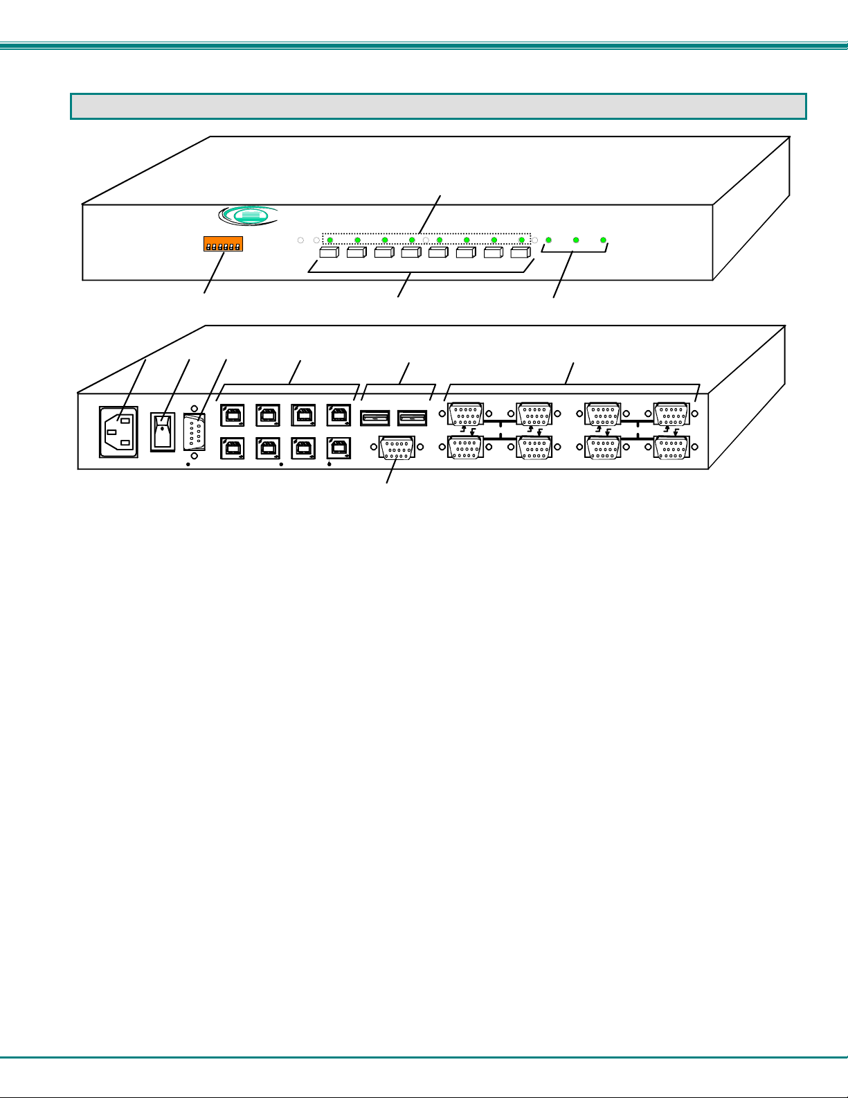
1. CPU Status LEDs- for visual indication of connection between the user and a specific CPU.
2. RS232- (optional) DIP switches for configuring switch address when RS232 is used
3. CPU Select Switches- push to manually switch to a specific CPU or change the switch operating mode
4. Mode Status LEDs- for visual indication of switch operating mode
5. IEC Connector- for attachment of country-specific power cord
6. Power Switch- to power up or power down the UNIMUX
7. RS232-(optional) 9DB male connector- for attachment of RS232 control cable
8. CPU x- USB type B female connector-for connection of USB device cable from CPU(s)
9. DEVICES- USB type A female connector- for connection of user USB device(s)
10. VIDEO-x- 15H D female connectors- for connecting video cables from CPUs
11. MONITOR- 15HD female connector- for connection of the user vid eo mo nitor
Front View of UNIMUX-USBV-8O -RS
1
Scan CommandBroadcast
1234
5678
Rear View of UNIMUX-USB V-8O-RS
910
USB DEVICES
MONITOR
11
8 4
7 3 6 2 5 1
VIDEOVIDEO
UNIMUX
TM
3
Page 8
NTI UNIMUX SERIES USB KVM SWITCH
RACKMOUNTING INSTRUCTIONS
This NTI switch was designed to be mounted to a rack or to sit on a desktop. It includes rackmount ears to make attachment to a
rack easy, and rubber feet to be applied to the bottom of the case if it will instead sit on a flat surface. If this will sit on a flat
surface, simply apply the rubber feet to the bottom of the case in each of the 4 corners.
To Mount to a Rack
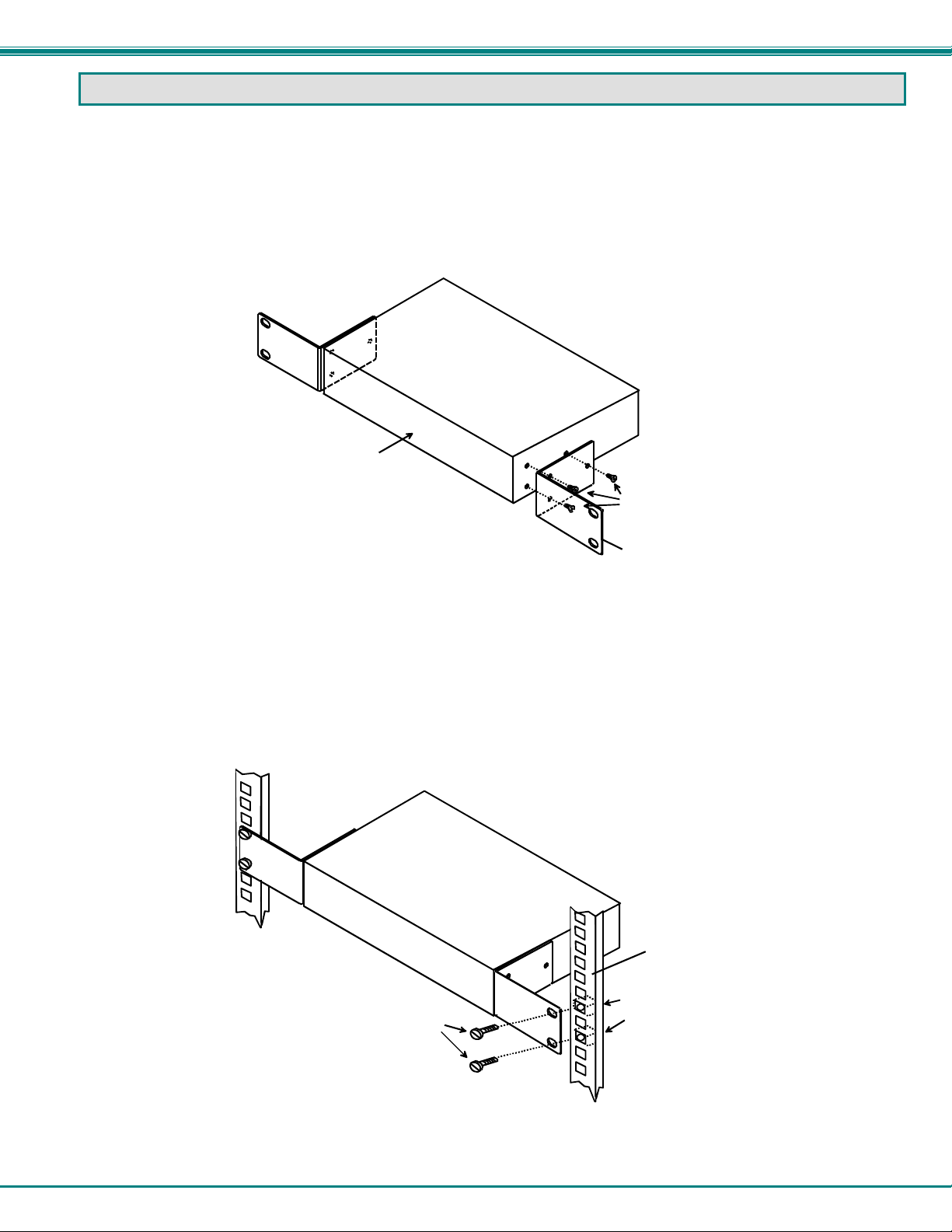
1. Attach the ears to the switch using the 6-32x3/16" flat Phillips-head screws (6) provided as shown in the illustration below.
The holes in the ears should line up with pre-threaded holes in the sides of the NTI switch. Tighten the screws securely.
Front of Switch
NTI Switch
6-32x3/16"
Flat Head
Screws
(Provided)
Rackmount Ear
Figure 1- Secure rackmount ears to switch
2. Install 4 captive nuts (not provided) to the rack in locations that line up with the holes in the mounting ear on the NTI switch.
3. Secure the NTI switch to the rack using four 3/16" diameter screws (not provided). Each screw should be of sufficient length
to go completely through the NTI mounting ear, rack frame and fully engage all threads in the captive nut. Be sure to
tighten all mounting screws securely.
4. Attach all cables securely to the switch and where necessary supply adequate means of strain relief for cables.
3/16" Diam eter Screw s
(not provided)
NTI Switch
Rack
Captive Nuts
(not provided)
Figure 2- Secure switch to a rack
4
Page 9
NTI UNIMUX SERIES USB KVM SWITCH
INSTALLATION
1. It is not necessary to turn the CPUs or monitors OFF during this installation.
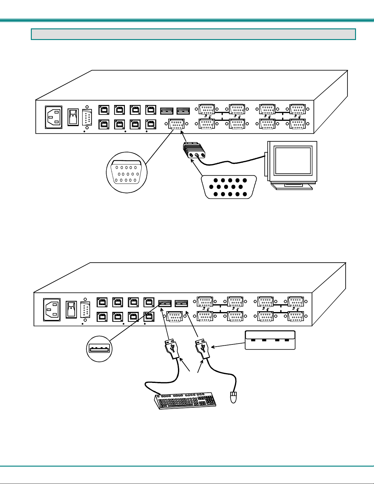
2. Connect the cable from a VGA multi-scan monitor to the 15HD connector labeled “MONITOR” on the UNIMUX (See Fig. 3
below.)
NETWORK TECHNOLOGIES INC Tel:330-562-70701275 Danner Dr, Aurora, OH 44202 www.nti1.com
CPU 8
R
S
2
CPU 4 CPU 3 CPU 2 CPU 1
3
2
15HD Female
Video Connector
CPU 7
CPU 6 CPU 5
Rear View of UNIMUX-USBV-8O-RS
USB DEVICES
MONITOR
15HD Male
Video Connector
8 4
7 3 6 2 5 1
VIDEOVIDEO
VGA
Multi-Scan
Monitor
Figure 3- Connect a VGA multi-scan monitor
3. Connect the male USB type A connector on the keyboard cable to either one of the two USB type A female connectors
labeled "DEVICES" on the rear panel of the UNIMUX.
4. Connect the male USB type A connector on the mouse cable to the remaining USB type A female connector labeled
"DEVICES".
NETWORK TECHNOLOGIES INC Tel:330-562-70701275 Danner Dr, Aurora, OH 44202 www.nti1.com
CPU 8
R
S
2
CPU 4 CPU 3 CPU 2 CPU 1
3
2
CPU 7
CPU 6 CPU 5
USB Type A Female
Rear View of UNIMUX-USBV-8O-RS
USB DEVICES
MONITOR
8 4
USB Type A
Male Connectors
USB Keyboard
7 3 6 2 5 1
USB Type A Male
USB
Mouse
VIDEOVIDEO
Figure 4- Connect the device(s)
5
Page 10
NTI UNIMUX SERIES USB KVM SWITCH
5. When cascading switches, follow the instruction on page 29 for "Cascading".
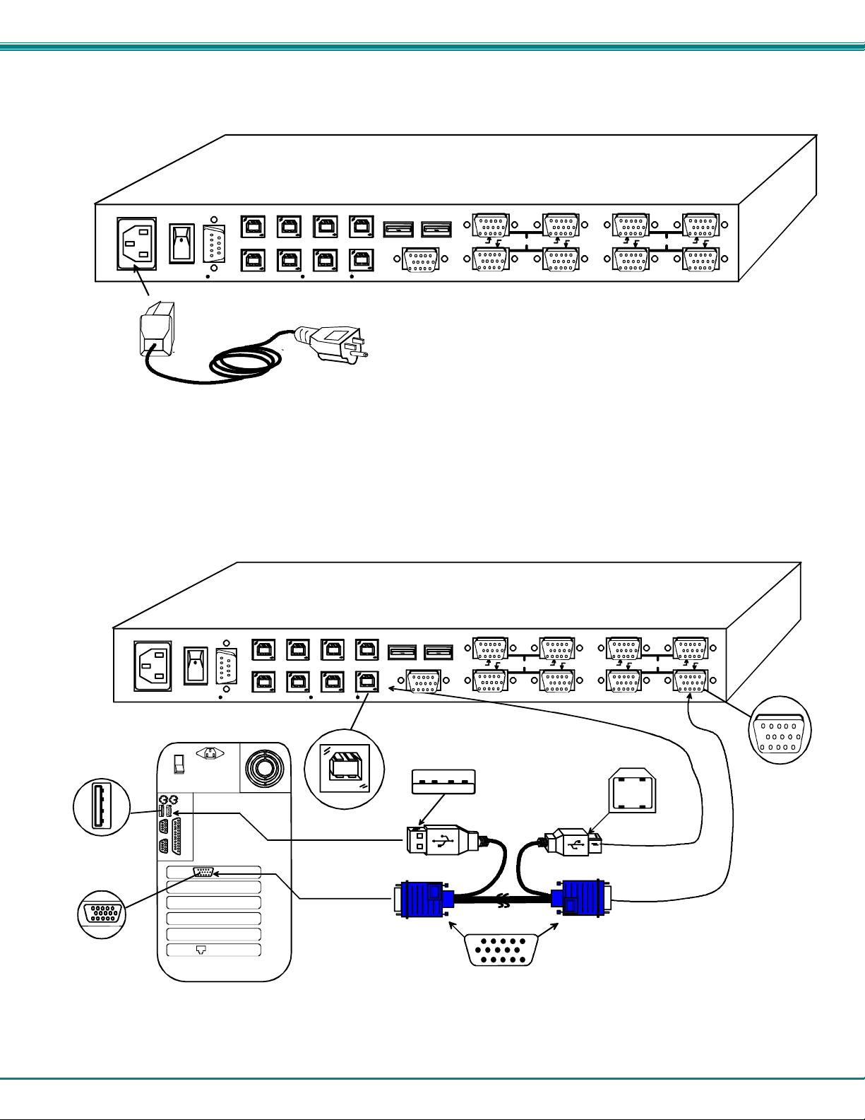
6. Connect the AC line cord to the UNIMUX. (See Fig. 5 below.)
Rear View of UNIMUX-USB V-8O-RS
NETWORK TECHNOLOGIES INC Tel:330-562-70701275 Danner Dr, Aurora, OH 44202 www.nti1.com
CPU 8
R
S
2
CPU 4 CPU 3 CPU 2 CPU 1
3
2
CPU 7
CPU 6 CPU 5
USB DEVICES
MONITOR
8 4
7 3 6 2 5 1
VIDEOVIDEO
IEC Powercord
Figure 5- Connect the AC line cord
7. Connect each CPU to the USB switch using a USBVEXT-xx-MM video and input device interface cable – REQUIRED
(not supplied). (See Fig. 6 below.)
8. Group the input device and monitor interface cables from each CPU, making sure that cables from the first CPU are
connected to the UNIMUX at connectors CPU 1 and VIDEO 1. Cables from the second CPU should
connect to CPU 2 and VIDEO 2 connectors...etc.
Rear View of UNIMUX-USB V- 8 O -R S
NETWORK TECHNOLOGIES I NC Tel:330-562-70701275 Danner Dr, Aurora, OH 44202 www.nti1.com
CPU 8
R
S
2
CPU 4 CPU 3 CPU 2 CPU 1
3
2
CPU 7
CPU 6 CPU 5
USB DEVICES
MONITOR
8 4
7 3 6 2 5 1
VIDEOVIDEO
Input Device Port
Rear View of Windows USB CPU
USB Type A Male
USB Type B
Male
USB Typ e A
Female
Video Port
15HD Female
Video Connecto r
USB Type B
Female
USBVEXT-xx-MM
15HD Male
Video Connector
Figure 6- Connect each CPU
15HD Female
Video Connector
6
Page 11
NTI UNIMUX SERIES USB KVM SWITCH
Power-Up Sequence
• The UNIMUX can be powered at any time.
• The CPUs can be powered at any time although if a CPU needs a keyboard and/or mouse at power-ON it should be powered
after connecting to and powering-ON the UNIMUX.
• USB input devices (keyboard and mouse) can be hot plugged to and from the UNIMUX at any time.
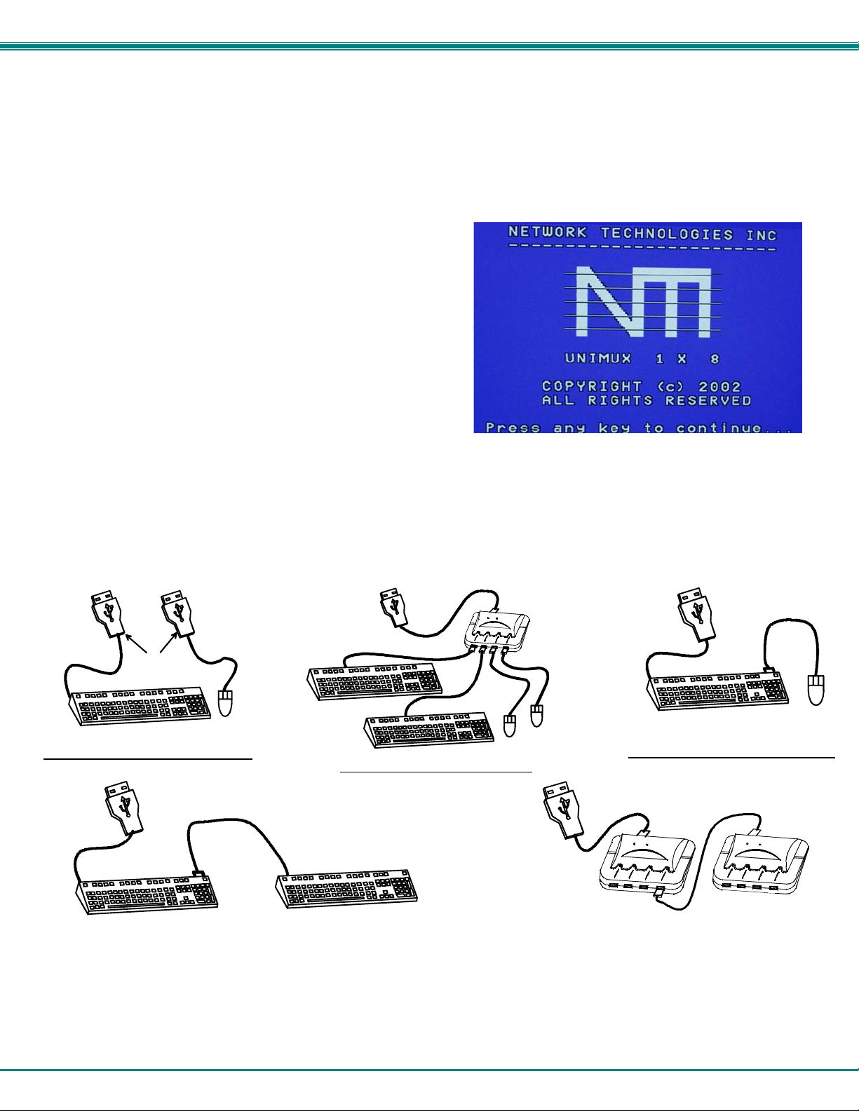
Immediately after powering ON the UNIMUX, the following splash screen will appear on the monitor (ex c ept on 2-port model):
If the security option is enabled (see page 12 for details on the
"Security Option"), when the UNIMUX is powered up the user will
be prompted for a username and password to continue. If the
security option is not enabled the monitor will display the desktop
image for the connected CPU and the user can continue with
normal operation of the connected CPU.
Limitations
• Only USB input device or hub cables can be connected to the UNIMUX at the USB Type A female ports labeled "DEVICES".
(See Features and Functions on page 3, item 11.)
• A USB hub (single or multi-port) can be used provided only USB input devices are plugged into it.
• Only a USB Windows or SUN keyboard or USB mouse may be connected to the USB port on a USB MAC keyboard
• A maximum of 8 input devices may be connected to the UNIMUX either directly or through hubs.
See Fig. 7 for some examples of input device combinations that can be used with the UNIMUX.
USB Type A
Male Connectors
USB Windows Keyboard
Typical Installation- 1 Keyboard, 1 Mouse
USB
Mouse
USB MAC Keyboard
USB Windows Keyboard
USB Windows Keyboard
Optional- Multiple keyboards and mice
USB MAC Keyboard
USB
Mouse
USB
Hub
USB
Mouse
USB MAC Keyboard
Optional- MAC USB keyboard and mouse
2 USB hubs in series (Dai sy-Chained)
USB
Mouse
Figure 7- Compatible device combinations
7
Page 12

NTI UNIMUX SERIES USB KVM SWITCH
USING THE UNIMUX USB KVM SWITCH
Once the UNIMUX is properly connected, the UNIMUX will enable a connection to be made between the CPUs attached to its
VIDEO and CPU ports and the monitor and input devices attached to the MONITOR and DEVICES ports. The LEDs on the
control panel of the UNIMUX will illuminate depending on w hich port (and corresponding CPU) is being connected to the monitor
and input devices.
The UNIMUX can be controlled by three methods:
• front control panel using touch-switches and LEDs
• keyboard control through Command Mode
• mouse clicks from within some menus of OSD Command Mode
Front Panel Control
There is a touch-switch and LED on the front panel of the UNIMUX for each CPU the switch will connect the monitor and
input devices to. Pressing any touch-switch on the front panel of the UNIMUX will connect the corresponding CPU to the monitor
and input devices.
Holding down any front panel touch-switch for more than 2 seconds will cause the UNIMUX to cycle through all modes of
operation including COMMAND, BROADCAST, SCAN, and NORMAL (described in "Basic Command Mode" on page 9 and in
"User Access Functions" starting on page 18). The three MODE LEDs on the front panel indicate which mode is selected.
Release the touch-switch when the LEDs indicate the desired mode. When no mode LEDs are illuminated the user is in Normal
Mode controlling directly the CPU to which the user is connected through the UNIMUX.
Keyboard Control
Keyboard control of the UNIMUX can be achieved using either of two methods:
• Basic Command Mode- operated strictly by using keyboard commands as instructed below. Basic Command Mode
is only applicable in UNIMUX-USBV-2.
• OSD Command Mode- operated using the keyboard and mouse in conjunction with OSD menus superimposed
onto the monitor. For all models other than UNIMUX-USBV-2, use the menus as instructed on page 12.
By pressing <Ctrl> + < ` > (accent key), the user can enter Command Mode (either Basic, or OSD). Once in Command
Mode, typing a series of commands will cause the UNIMUX to connect the user to any one CPU connected to the switch.
Pressing the <Esc> key will exit Command Mode.
8
Page 13
NTI UNIMUX SERIES USB KVM SWITCH
y
MODES OF OPERATION
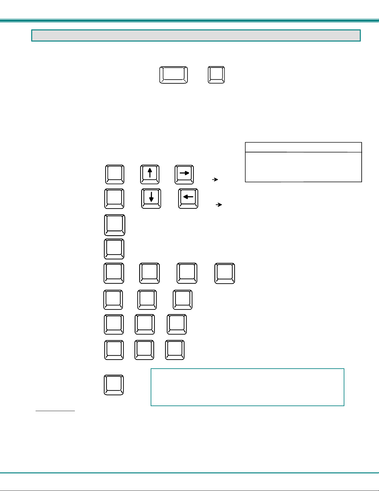
Basic Command Mode
In order to control the UNIMUX with the keyboard connected, Command Mode must be enabled. To enter Command Mode from
the keyboard:
Press
Ctrl
+
NOTE: Basic Command mode is only used in a UNIMUX-USBV-2. All other UNIMUXUSBV-x switches have OSD installed. To control these models, proceed to “OSD
CONTROL” on page 12. If this is a UNIMUX-USBV-2, continue on this page.
When the COMMAND LED is illuminated, all 3 status lights on the keyboard will illuminate (if they aren't already due to caps lock,
scroll lock, and/or num lock) to indicate that Command Mode is enabled and the following functions are available:
Basic Command Functions
Function: Keystroke:
Increment Port
Decrement Port
Toggle Scan Mode
ON and OFF
Toggle Broadcast Mode
ON and OFF
Set scan time-out
period for each port.
Select a specific
port
Configure port to connect
To a MAC CPU
Configure port to connect
To a Windows or SUN
CPU
Exit Command Mode
Ioror
D
S
B
T
P
M
W
Esc
oror
(The SCAN Mode LED will
also toggle ON and OFF)
(The Broadcast Mode LED
will toggle ON and OFF.)
(0-2)
-
-
+
+
x
0
0
0
-
x
-
x
+
x
+
FYI: The user must exit Command Mode to type to a CPU.
To exit Command Mode, either hold down any touch-switch on the
front panel for more than 2 seconds, OR press <ESC> on the
board.
ke
(select the next
higher port
ex. 01 02)
(select the next
lower port
ex. 02 01)
(0-9)
x
-
(P0x would be P01 or P02)
(x= 1or 2 <M> + <0> + <1> will enable function on Port 1
<M> + <0> + <2> will enable function on Port 2. Keyboard
LED's will flash once to confirm command. )
(x= 1or 2 <W> + <0> + <1> will disable function on Port 1
<W> + <0> + <2> will disable function on Port 2. Keyboard
LED's will flash once to confirm command. )
Scan Mode
To activate or deactivate Scan Mode press <S> while in Command Mode. When in Scan Mode the switch scans to each port
with a CPU powered-ON. (The SCAN LED on the front panel will illuminate and remain ON while in Scan Mod e. ) T he port with
the CPU powered-ON remains active while in use until it becomes idle for the configured dwel l time (default time-out period is 5
seconds) before switching to the next powered-ON CPU port. See Command Mode section above for configuring the scan dwell
time.
Note: The keyboard and mouse must remain idle for the full scan dwell time before the switch selects the next active
port.
~
`
`
(0-9)
x
(ACCENT
KEY)
KEY SYMBOLS LEGEND:
or
PRESS EITHER KEY
CHORDED SEQUEN CE- PRESS CONSECUTIVELY
AND KEEP KEYS PR ESSED UNTIL ALL ARE PRESSED.
+
PRESS CONSECUTI VEL Y
-
(xxx from 002 to 255. ie. T00 2
would set the time-out period
for 2 seconds)
9
Page 14

NTI UNIMUX SERIES USB KVM SWITCH
Broadcast Mode
To activate or deactivate Broadcast Mode press <B> while in Command Mode. Broadcast Mode enables the user to type
characters to both computers simultaneously.
NOTE: The user must type somewhat slowly when in Broadcast Mode (less than 20 wpm) and cannot use the
<Backspace> key.
Normal Mode
When all of the UNIMUX mode LEDs are OFF the user is in Normal Mode, controlling the CPU to which the user is connected
through the UNIMUX.
No SUN Sleep Mode
PLEASE NOTE: It is necessary to configure a SUN CPU (most versions) such that the Sleep Mode is not enabled. If the
SUN CPU goes into Sleep Mode either automatically or manually, the user must reboot the SUN CPU in order to resume
use of the SUN CPU.
To disable the Sleep Mode, perform the following steps:
1. Select "Power Manager"
2. Look for "Device Idle Time Before Power Saving Starts"
3. Select "Always ON"
4. Look for "Override Device Idle Time For:"
5. Make sure neither "Monitors" nor "Disks" are selected.
Select Country Code
It is possible to configure the UNIMUX to emulate a specific international SUN keyboard regardless of what actual keyboard is
connected. This is recommended when the CPU needs the layout code (i.e. a SUN CPU) and the keyboard doesn't have an
explicit layout code (i.e. some Windows keyboards). To do this, manually set the UNIMUX to indicate the international keyboard
identification number to the CPU using the following procedure;
1. Connect the keyboard to be used to the UNIMUX
2. Enter Command Mode
3. Type Lxx, where xx is the number from the list below that corresponds to the desired country code
4. Exit Command Mode
5. Reboot the CPU connected to the UNIMUX
Country Codes
00 Auto Detect 13 International (ISO) 26 Swedish
01 Arabic 14 Italian 27 Swiss/French
02 Belgian 15 Japan (Katakana) 28 Swiss/German
03 Canadian-
Bilingual
04 Canadian-French 17 Latin American 30 Taiwan
05 Czech Republic 18 Netherlands/Dutch 31 Turkish
06 Danish 19 Norwegian 32 UK
07 Finnish 20 Persian (Farsi) 33 US
08 French 21 Poland 34 Yugoslavia
09 German 22 Portuguese
10 Greek 23 Russia
11 Hebrew 24 Slovakia
12 Hungary 25 Spanish
16 Korean 29 Switzerland
Figure 8- Country Codes for international SUN keyboards
For more on international SUN keyboards, see page 32.
10
Page 15

NTI UNIMUX SERIES USB KVM SWITCH
Mice and Trackballs with MACs
The UNIMUX can be configured to enable full functionality between mice and trackballs having two or more buttons and USB
MAC CPUs. By default, the ports on the UNIMUX are configured for use with WINDOWS and SUN CPUs and have no specia l
translation for using multi-function mice and trackballs when a MAC CPU is connected. Using the commands <M> + <x> + <x>
(xx = port number), or <W> + <x> + <x> in Command Mode (page 8), either enable or disable this feature as needed for each
port.
NOTE: Be sure to reconfigure port for connection to a WINDOWS or SUN CPU if a MAC CPU is removed and a
WINDOWS or SUN CPU is then connected.
11
Page 16
NTI UNIMUX SERIES USB KVM SWITCH
OSD CONTROL
OSD superimposes a menu system on the user’s video screen with a list of all connected CPUs. OSD allows CPUs to be named
(with up to 12-character names). OSD then allows selection of CPUs by that name. Connected CPUs can be listed by name or
by port number. OSD Search Mode enables the user to type in the first few characters of the CPU's name and the OSD will locate
it. Help screens assist with all OSD functions.
Security Option
The security option of the OSD Control enables an administrator to control access to CPU ports for each user. Up to 63 users
can be created. These users have controlled access to any CPU. Only the administrator can activate or deactivate the security
features. Security can be activated from the Maintenance Mode menu (page 24) with a successful administrator login for
verification purposes. Furthermore, the administrator can set a maximum idle time value after which the current user will be
logged out and the login screen displayed. This time out does not function while the OSD is active. The current security status,
idle time out, and scan dwell time are all saved and will be restored whenever power to the switch is cycled OFF, then ON. To
reset the administrator's password call NTI and have the device serial number of the UNIMUX available.
Enabling the Security Feature
To enable the security feature the administrator must first enter Command Mode from the keyboard using the sequence
<Ctrl> + <`> (accent key). The OSD menu will automatically appear on the monitor in addition to illuminating the Command Mode
indicator LED on the UNIMUX. This provides a visual way to control the UNIMUX using the keyboard and mouse.
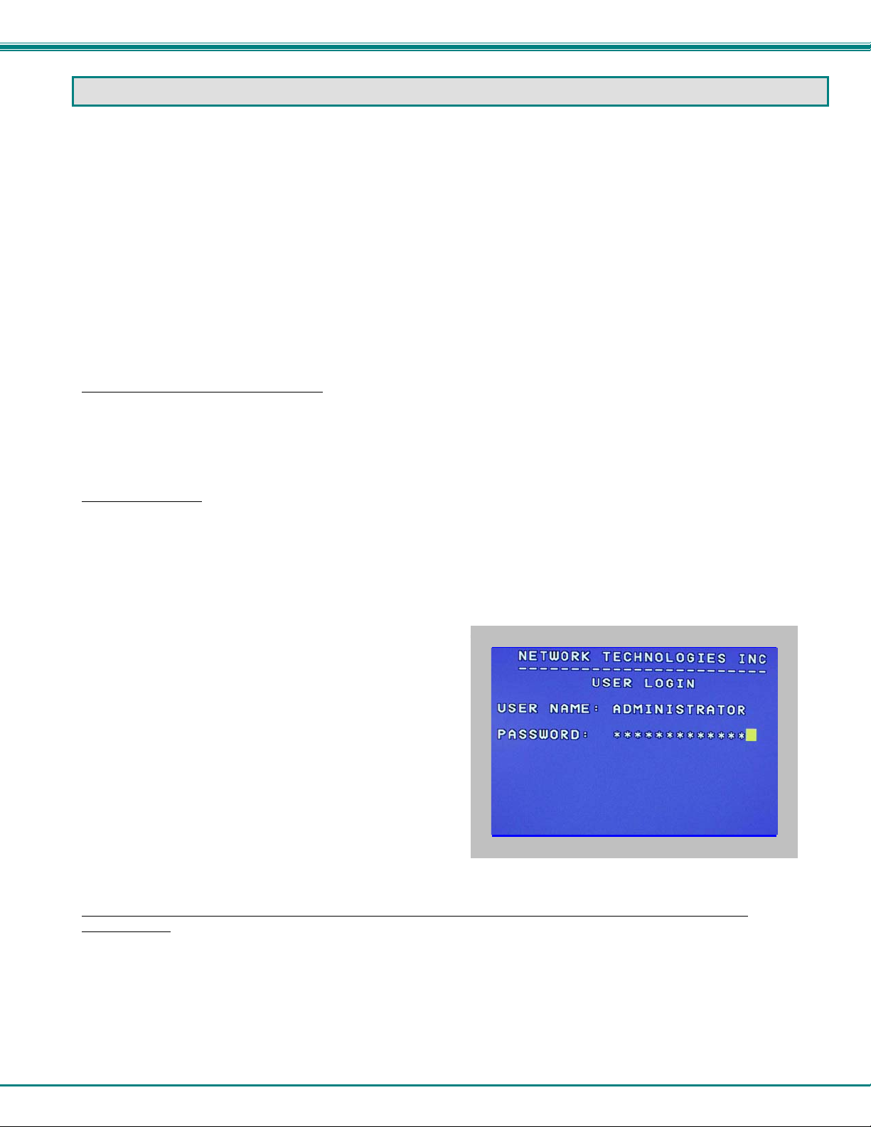
The administrator , when setting the USB KVM switch up for the first time, may want to proceed directly to the
ADMINISTRATION Mode by typing <Ctrl> +<M> , then <A>, and then <Y>.
The factory settings are:
• default user name = ADMINISTRATOR
• default password = ADMINISTRATOR
Note: The user name for the administrator cannot be
changed from "ADMINISTRATOR".
FYI: Capital letters are introduced by keeping the <Shift>
key pressed while typing. The <Capslock> does not work
while in OSD.
Once logged-in, follow the instructions on page 15 for setting up
users and changing the password. Once the password is setup, if
it is lost or forgotten the administrator will have to contact NTI for
assistance on clearing the password and set it up again. Within
the Administration Mode the administrator can setup each of the
users and the limitations of their use of the individual CPUs
attached to the switch.
Figure 9- Administrator Login screen
When a standard user powers up the system a security screen will appear if security has been enabled by the
administrator. The user will need to login to the switch by following the instructions on page 13 for the USER LOGIN. If the
user does not know the appropriate user name and password (setup by the administrator), contact the switch administrator for this
information. Once logged-in a user can follow the Command Mode functions described on page 16 to control the switch within
the limitations as determined by the administrator.
12
Page 17
NTI UNIMUX SERIES USB KVM SWITCH
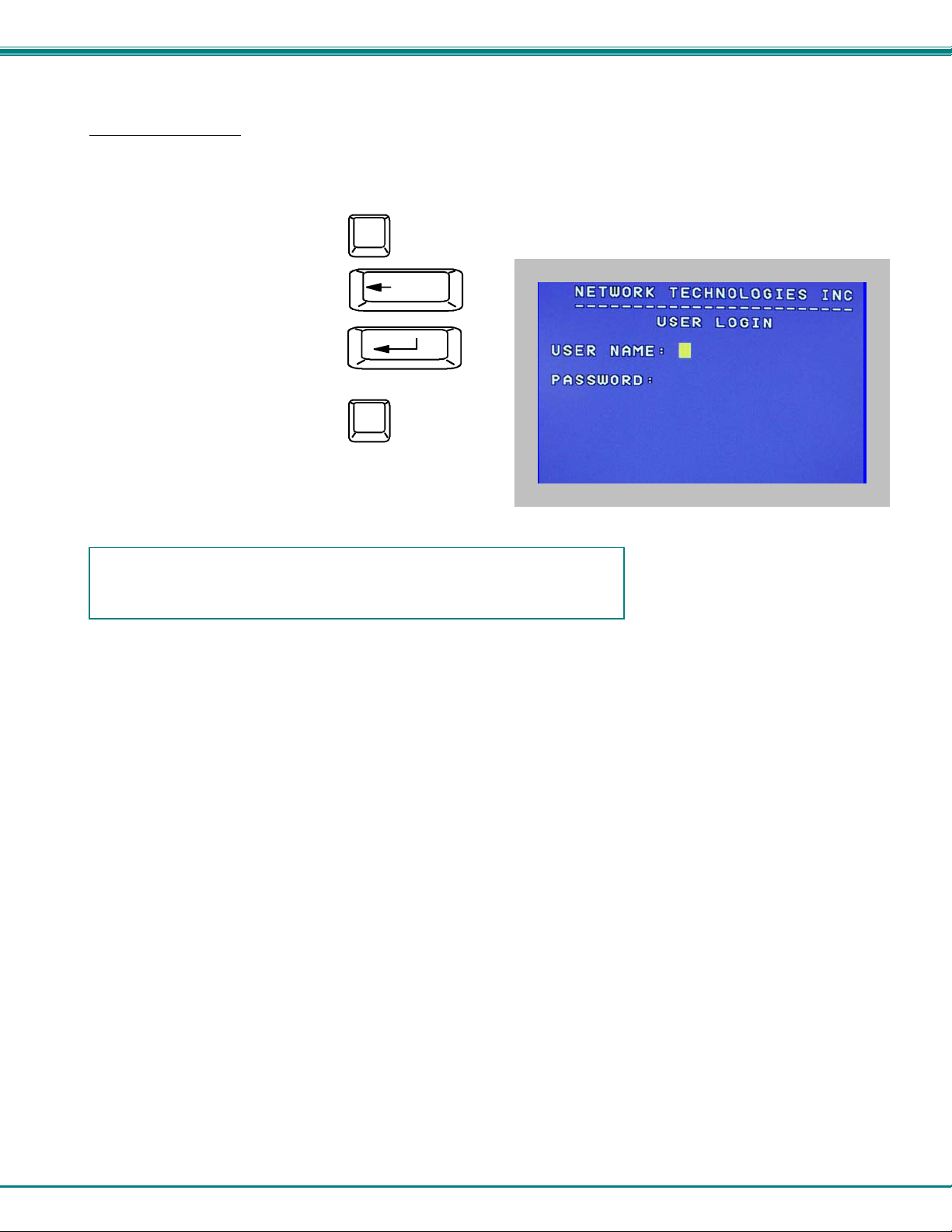
User Login Mode
User login mode requires a user to login with a user name and password from the list created by the administrator. This mode will
also disable use of the front panel until the user logs in.
Function: Keystroke:
Add a character to the
user name/password
Remove previous character
from the user name/password
Submit user name/password
Exit USER LOGIN and return
to previous mode. This function
is only available if security is
not currently active.
A-Z
(Type any alphabetical or numeric character)
0-9
Backspace
Enter
Esc
Figure 10- User Login screen
If the password submitted is incorrect, the user will not be able to proceed.
If the password submitted is correct, the user will proceed to Normal Mode.
13
Page 18
NTI UNIMUX SERIES USB KVM SWITCH
ADDITIONAL MODES AVAILABLE WITH SECURITY
The three modes that follow are only available if the administrator is logged in.
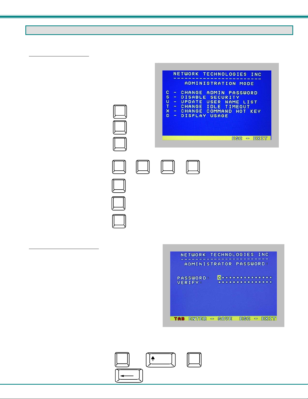
Administration Mode
To enter the Administration Mode menu press <A> from the
Maintenance Mode menu (page 24).
Administration Mode allows the administrator to use the
following functions:
Function: Keystroke:
Change the administrator’s
password
Disable security
Update User Name List
Figure 11- Administration Mode menu
Select the idle time in minutes
Change Alternate Command
Hot Key
Display Usage Statistics
Exit Administration Mode and
return to previous mode
C
S
U
T
X
D
Esc
(0-2)
-
x
(See page 16 for details)
(0-9)
-
x
(xxx from 000 to 25 5. i.e. T002
(0-9)
-
would set the time-out period
x
for 2 minutes. 000 will disable it)
Administrator Password
To change the administrator password press <C> from the
Administration Mode menu.
The administrator is able to change the administrator password
as needed (see Fig. 12). Two edit fields are available, one for
password, the other for verify password. The password can be
up to 15 characters in length.
Note: The default password for the administrator is
ADMINISTRATOR.
Figure 12- Administrator password change
Function: Keystroke:
Add character to password string
or verify password string
Delete previous character in
edited string
A-Z
0-9
Backspace
or
Shift
14
+
(Type any upper or lower case
A-Z
alphabetical or numeric character)
Page 19

NTI UNIMUX SERIES USB KVM SWITCH
U
Save new password.
Move to next field to be edited
Return to Administration Mode
Enter
Tab
Esc
(If Password string and Verify Password string
are different, this command will have no effect,
enabling the administrator to correct the password)
User Name List
To enter the User Name List press <U> from the Administration Mode menu.
The User Name List displays the list of users and provides control for adding new users (up to 63), changing or assigning user
passwords, and changing access rights for any given user. User names may be up to 12 characters long, may not contain
spaces, and are not case sensitive. Passwords may be up to 15 characters long, may not contain spaces, and are case sensitive.
Function: Keystroke:
Select previous user in the list
Select next user in the list
Scroll the list with one page up
Scroll the list with one page down
Edit selected user settingsEnter Edit User Mode
Return to Administration Mode
Return to previous mode
Page
Up
Page
Down
E
Esc
Figure 13- User Name List screen
Edit User
To enter the Edit User mode press <E> from the User Name List after selecting a user or an empty record.
The Edit User mode (see Fig. 14) enables the administrator to:
- add a new user
- remove an existing user
- edit the settings for an existing user
The Edit User mode contains three edit boxes and a check box list of
up to 32 check boxes representing the User Access List (list of the
CPU port(s) the user has access rights to).
The first edit box is used to edit the user name. The next two edit
boxes are used to input the password twice (in order to verify it was
typed correctly). The password can be up to 13 characters in length.
The check boxes are used to control the user access to the CPU ports.
The user will only have access to check boxes with checks in them.
Figure 14- Edit the user access list
ser Access List
15
Page 20

NTI UNIMUX SERIES USB KVM SWITCH
The list below describes the functions available in the Edit User mode:
Function: Keystroke:
Add a character to user name string,
password string, or verify password
string, whichever is selected
Switch sequentially between the
User Name edit box, Password
edit box, Verify Password edit
box, and User Access List
Navigate through User Access
List when it is active
Toggle access rights (check/
uncheck) of the highlighted
port in the User Access List
Save the edited configuration.
Administrator will be prompted for
a Yes or No confirmation
Go back to User Name List menu
NOTE: To delete a user from the User Name List, use either the <Delete> key or the <Backspace> key to remove
characters, not the <Spacebar>. Using the <Spacebar> will overwrite the chara cters with spaces and retain th e
user configuration in the User Name List.
A-Z
0-9
Tab
Enter
Esc
or
Shift
+
A-Z
alphabetical or numeric character)
(Type any upper or lower case
or
(Spacebar)
(If Password string and Verify Password string
are different, this command will have no effect,
enabling the administrator to correct the password)
Alternate Command Hot Key
To enable the administrator to assign a key in addition to the <`> (accent key) to use with <Ctrl> to enter into OSD Command
Mode, an Alternate Command Hot Key option is provided. The default factory setting for this option is <`> (disabling the option).
To select an Alternate Command Hot Key, press <X> from Administration Mode menu (page 14). A window will open and the
administrator will be prompted to press a key. After pressing the key, a confirmation message will appear. The administrator
should press <Y> (Yes) to validate the key as the Alternate Command Hot Key, or <N> (No) to select another key. Pressing
<Esc> will return to the Administration Mode menu.
Only the administrator is allowed to set or change the Alternate
Command Hot Key. This function must be set individually for each
of the USB User Device ports on the UNIMUX USBV-x USB KVM
switch .
Note: The Alternate Command Hot Key does not replace the
<`> (accent) key, it just works as another way to enter into
Command Mode. After setting it, the user can enter into
Command Mode either with <Ctrl> + <`> or with <Ctrl> +
<Alternative Command Hot Key> combination. To disable it,
the administrator should set <`> as the Alternate Command
Hot Key.
Figure 15- Alternate Command Hot Key
16
Page 21
NTI UNIMUX SERIES USB KVM SWITCH
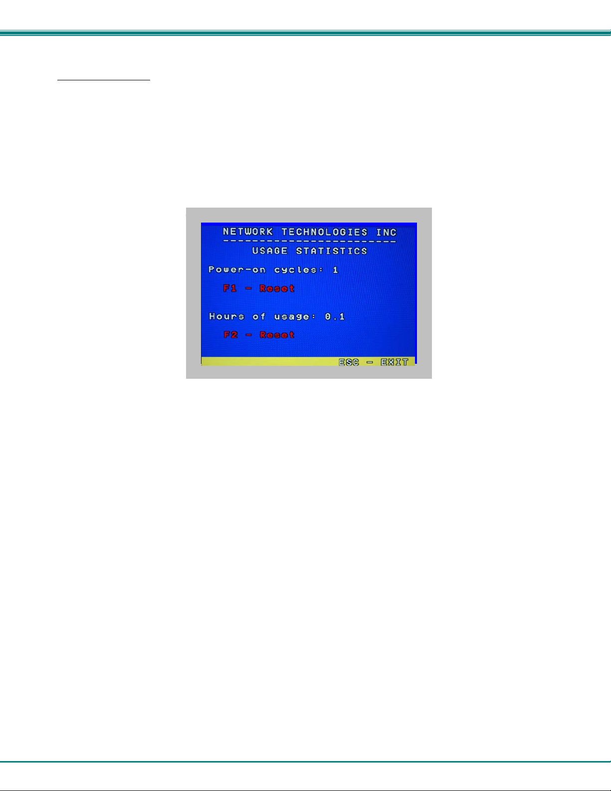
Usage Statistics
To view the Usage Statistics press <D> from the Administration Mode menu.
The Usage Statistic screen has two resetable counters.
• “Power-on cycles” indicates how many times the UNIMUX has been powered-cycled since the counter was last reset. To
reset the “Power-on cycles” counter, press the <F1> key.
• “Hours of usage” indicates how many hours of total operation the UNIMUX has had since it was last reset. The hours of
usage will continue to be added to regardless of how many times the UNIMUX is power cycled. To reset the “Hours of
usage counter” to 0, press the <F2> key.
Figure 16- Usage Statistics screen
17
Page 22
NTI UNIMUX SERIES USB KVM SWITCH
USER ACCESS FUNCTIONS
Introduction
The OSD menu enables a user to name the CPUs connected to the UNIMUX and conne ct to them using that name from a single
keyboard and mouse. The OSD is positioned on the user's monitor, displaying 8 CPU names at a time. The screen can be used
for switching as well as editing the CPUs’ names. Through the OSD menu, the user can operate the UNIMUX to have the switch
cycle through 3 extended modes of operation: COMMAND, BROADCAST, and SCAN . Three LEDs on the front panel indicate
when these modes are enabled.
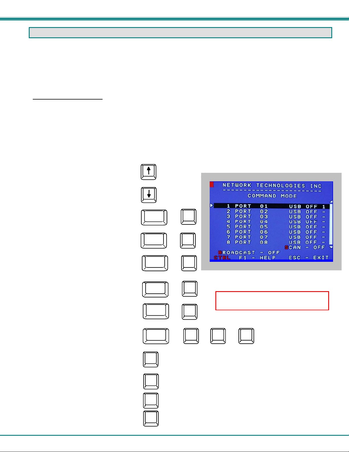
OSD Command Mode
When entering the Command Mode from the keyboard using the <Ctrl> + <`> (accent key), the OSD menu will automatically
appear on the monitor in addition to illuminating the COMMAND indicator LED on the USB KVM switch. T his provides a visual
way to control the UNIMUX.
The list below describes the OSD Command functions available from the keyboard after entering Command Mode and while the
COMMAND LED is illuminated:
Function: Keystroke:
Select the previous port
Select the next port
Enable/disable Scan Mode
Ctrl
+
S
Enable/disable Broadcast Mode
Enter Edit Mode
Enter Maintenance Mode
Enter Change Settings Menu
Select a specific port
Enter Search Mode and add a character
to search string and select the CPU’s
name that matches best.
Select the first port on the switch
Select the last port on the switch
Display Help Menu
Ctrl
Ctrl
Ctrl
Ctrl
Ctrl
A-Z
0-9
Home
End
F1
B
+
E
+
Figure 17- Command Mode screen
M
+
NOTE: Edit Mode will only be accessible
if the administrator is logged in.
+
T
P
+
(Type any alphabetical or numeric character)
(0-9)
-
x
(0-9)
-
x
(Pxx would be P01, P02, etc.)
18
Page 23

NTI UNIMUX SERIES USB KVM SWITCH
OSD Command Mode (Cont'd)
Function: Keystroke:
Switch to a selected port
Update Configuration
Display port information
Exit OSD Command Mode
Press <CTRL> while in the Command Mode menu
to display the Edit, Maintenance, Port, and Settings
control features.
Note: The user must exit Command Mode to
type to a CPU.
To exit Command Mode, either hold down any
touch-switch on the front panel for more than 2
seconds, OR press <ESC> on the keyboard.
Enter
Ctrl
(Display information about the selected port. When pressed,
F3
a window displays the port name and its position in the configuration
structure by level and port number.)
Esc
+
Tab
(Use this command to update the information
describing the structure of the cascaded
switches. Used if a slave is powered-ON or
OFF at any time after initial startup.)
Figure 18- More Command Mode features
The mouse can also be used to control the UNIMUX within the Command Mode menu.
• The mouse cursor can be moved to the Scan, Help, Broadcast, Settings, Maintenance, and Exit fields where the user
can then click on the left mouse button to perform that function.
• Ports listed on the screen can be selected by moving the cursor onto that port and clicking. Clicking twice on a
selected port will switch to that port and exit Command Mode.
• To change the displayed ports on the screen simply click on the up and down arrows located to the right of the port
names displayed.
Broadcast Mode
To activate or deactivate Broadcast Mode press <Ctrl> + <B> from the Command Mode menu.
Broadcast Mode enables the user to type characters to more computers simultaneously. From the Change Settings menu (see
page 19) the user can edit the list of ports that receive data in Broadcast Mode. A port doesn’t receive broadcast data if one of the
following conditions is true:
- the port is not in the Broadcast Mode list
- Security Mode is enabled and the user does not have access rights to the port
Note: The user must type somewhat slowly when in Broadcast Mode (less than 20 wpm) and cannot use the
<Backspace> key.
Scan Mode
To activate or deactivate Scan Mode press <Ctrl> + <S> from the Command Mode menu.
When in Scan Mode the switch scans to each port with a CPU powered-ON. (The SCAN LED on the front panel will illuminate and
remain ON while in Scan Mode.) The port with the CPU powered-ON remains active while in use until it becomes idle for the
configured dwell time (default time-out period is 5 seconds) before switching to the next powered-ON CPU port. See Command
Mode section above for configuring the scan dwell time.
Note: The keyboard and mouse must remain idle for the full scan dwell time before the switch selects the next active
port.
19
Page 24
NTI UNIMUX SERIES USB KVM SWITCH
Note: The scan dwell time set by the user only effects that user and has no effect on other switch users.
Normal Mode
When the UNIMUX is not in Command, Broadcast, or Scan mode and all of the UNIMUX mode LEDs are OFF, the user is in
Normal Mode, controlling the CPU to which the user is connected through the USB KVM switch.
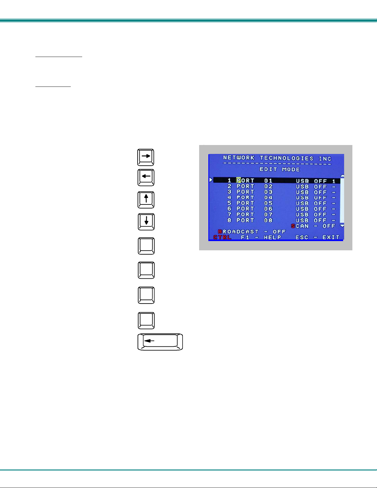
Edit Mode
Note: Edit Mode will only be accessible if the administrator is logged in.
To activate Edit Mode press <Ctrl> + <E> from the Command Mode menu.
Edit Mode enables the administrator to modify the names of the CPUs connected to the switch. Names of CPUs can be up to 12
characters in length. Use the <Shift> key to introduce capital letters (the <Capslock> does not work in OSD).
Function: Keystroke:
Move cursor one position
to the right
Move cursor one position
to the left
Move cursor to the
previous port
Move cursor to the
next port
Selects the first port on
the switch
Home
Figure 19- Edit Mode screen
Selects the last port on
the switch
Toggles between insert
and overstrike
Erase current character
Erase previous character
When finished making changes in Edit Mode, press <Enter> and a prompt will appear to press either <Y> to save the chan ges or
<N> to continue making changes without saving the changes just made. If the <Esc> key is pressed instead of <Enter>, all
changes made will be ignored and the display will return to the previous m enu.
End
Insert
Delete
(The character either gets inserted and the remainder of the name
gets shifted to the right, OR the current character gets overwritten.)
Backspace
20
Page 25
NTI UNIMUX SERIES USB KVM SWITCH
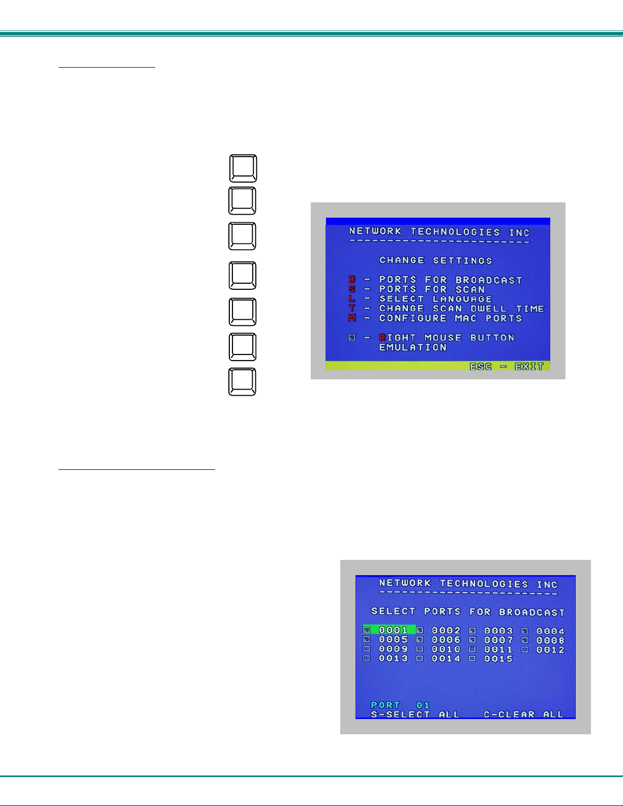
Change Settings
To enter the Change Settings menu (see Fig. 20) press <Ctrl>+<T> from the Command Mode menu.
The list below describes the Change Settings menu functions available from the keyboa rd:
Function: Keystroke:
Go to Broadcast Mode Configuration
Go to Scan Mode Configuration
B
S
Go to Language Selection Menu
(Option only available if the
administrator is logged in)
Change the scan dwell time period
Configure ports for MAC or non-
MAC CPUs (Administrator only)
L
T
M
Enable/Disable right mouse button
click emulation
Exit from Change Settings
Return to Command Mode
Figure 20- Change Settings menu
When the <T> is pressed, an edit field showing the actual value of the scan dwell time is displayed at the bottom of the Change
Settings menu. The user can introduce a new value for scan dwell time and press <Enter> to save it or <Esc> to exit. Any value
between 002 and 255 (seconds) is acceptable.
R
Esc
Select Ports For Broadcast
To Select Ports For Broadcasting, press <B> from the Change Settings menu (see Fig. 20).
The Select Ports For Broadcast menu (see Fig. 21) enables the user to select specific ports to be active in Broadcast Mode. Only
the selected ports will receive keyboard messages in Broadcast Mode.
A checklist with all the port numbers will be displayed in the window.
• unchecked box = the corresponding port is not in the
broadcast list
• checked box = the corresponding port is in the
broadcast list
The user can toggle the state of the selected check box by
pressing <Spacebar> or clicking the left mouse button.
• press <S> to check all of the ports
• press <C> to uncheck all of the ports
The selected port is highlighted with a green bar. To select another
port, the user can use the arrow keys or mouse movement. The
name of the selected port is displayed at the bottom left of the
menu.
When <Esc> is pressed the display will return to the Change
Settings menu. The broadcast selection list is automatically saved.
Figure 21- Select ports for broadcasting
21
Page 26
NTI UNIMUX SERIES USB KVM SWITCH
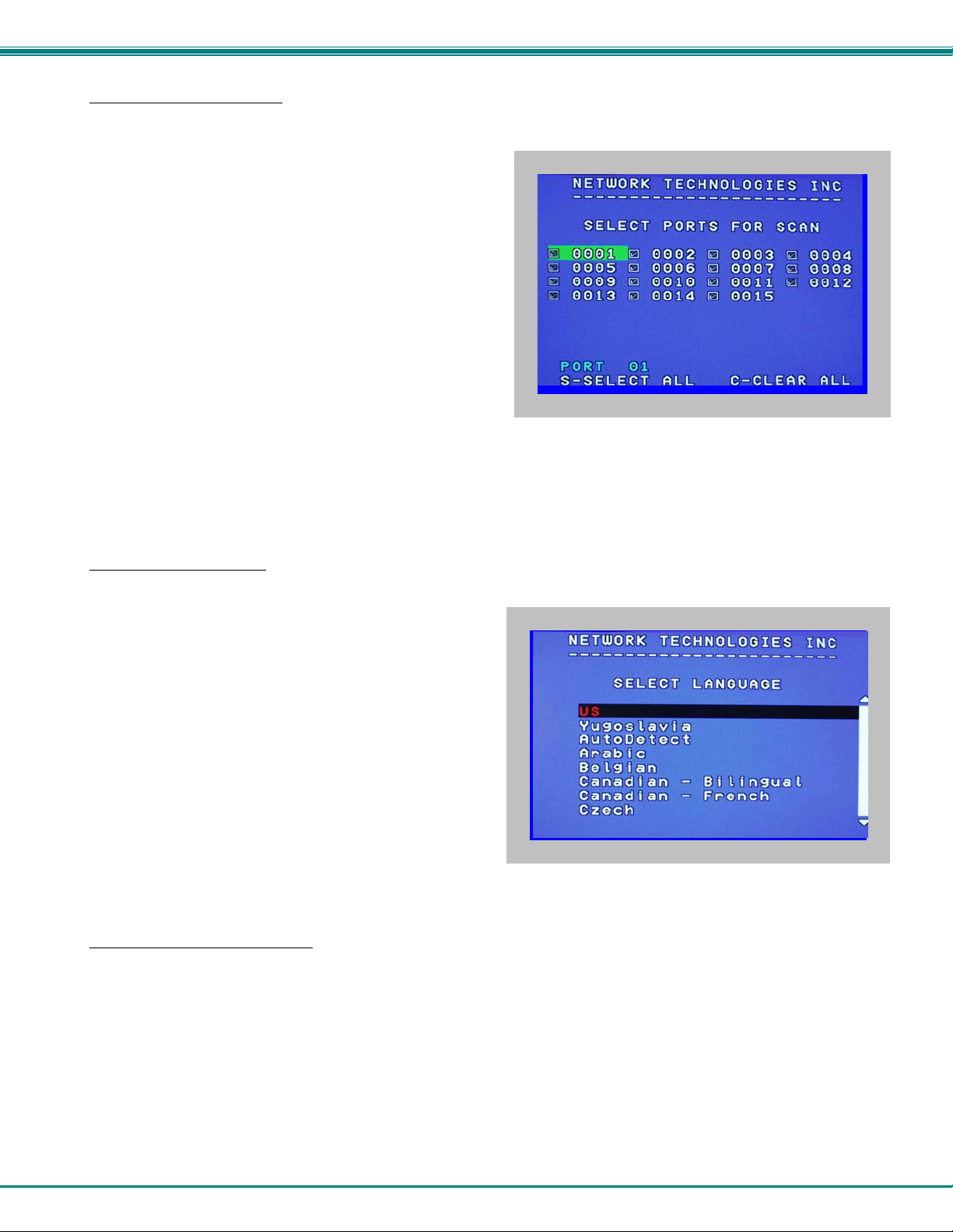
Select Ports For Scan
To Select Ports For Scanning, press <S> from the Change Settings menu described on page 21.
The Select Ports For Scan menu enables the user to select
specific ports to be active in Scan Mode. Only the sel ected ports
will be scanned in Scan Mode.
A checklist with all the port numbers preceded by a check box will
be displayed in the window.
• unchecked box = the corresponding port is not in the
scan list
• checked box = the corresponding port is in the scan
list
The user can toggle the state of the selected check box by
pressing <Spacebar> or clicking the left mouse button.
• press <S> to check all of the ports
• press <C> to uncheck all of the ports
Figure 22- Select ports for scanning
The selected port is highlighted with a green bar. To select another port, the user can use the arrow keys or mouse movement.
The name of the selected port is displayed at the bottom left of the menu.
When <Esc> is pressed the display will return to the Change Settings menu. The scan selection list is a utomatica lly saved.
Language Selection
Note: The LANGUAGE SELECTION option will only be accessible if the administrator is logged in.
To enter the Select Language menu press <L> from the Change
Settings menu described on page 21.
The Language Selection menu enables the user to manually
configure the UNIMUX to emulate a specific international SUN
keyboard regardless of what actual keyboard is connected.
This is recommended when the CPU needs the layout code (i.e.
a SUN CPU) and the keyboard doesn't have an explicit layout
code (i.e. Windows keyboards).
To choose a language, scroll through the menu (using either the
mouse or up/down arrows) and when the desired language is
highlighted press <Enter> on the main keyboard. The selected
language will be highlighted in red. Press <Esc> to return to the
Change Settings menu.
Figure 23- Select the keyboard language
For more on International SUN keyboards, see page 32.
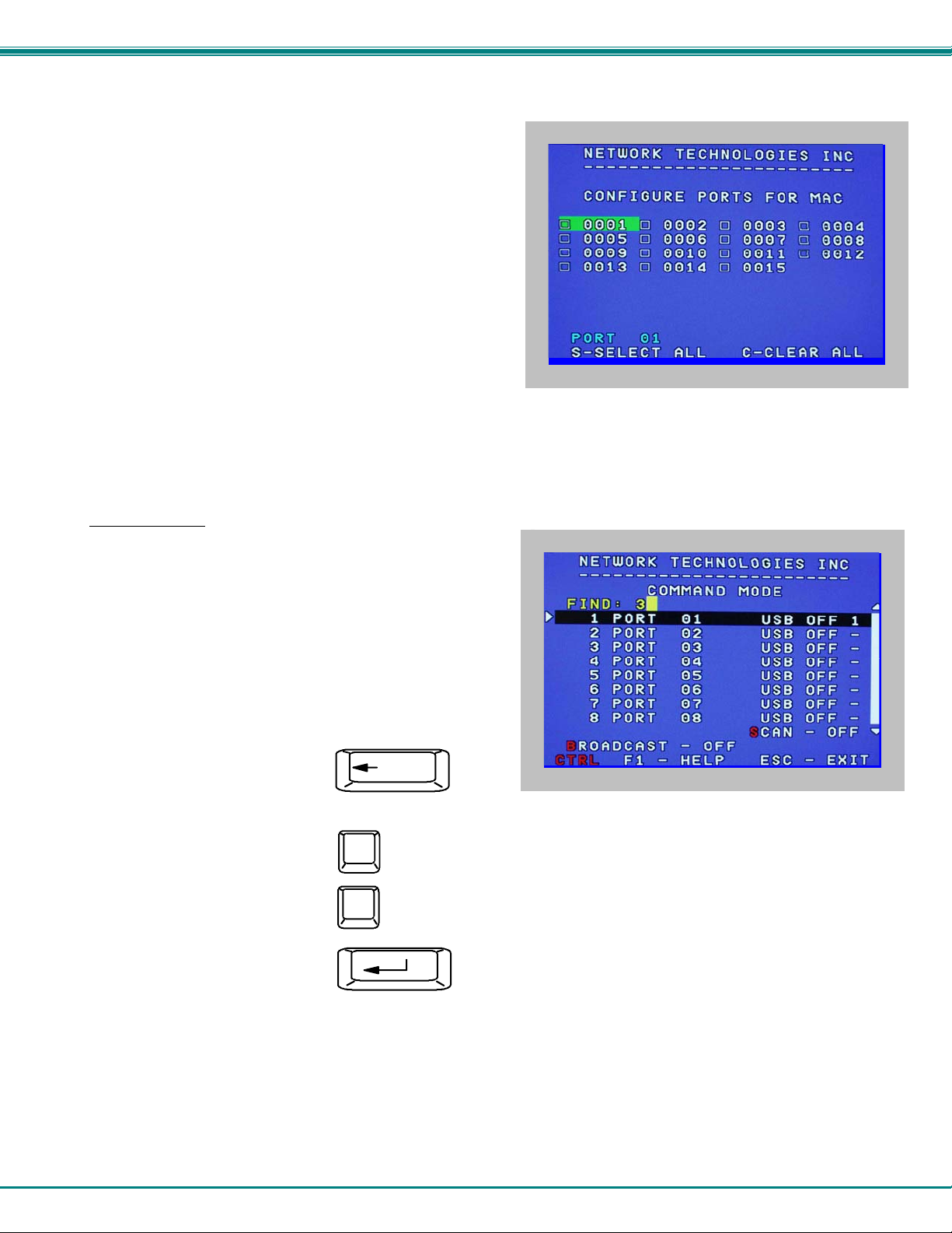
MAC Ports Configuration
Note: The CONFIGURE MAC PORTS option will only be accessible if the administrator is logged in.
MAC Ports Configuration menu enables the administrator to select specific ports to be connected to MAC CPUs for passing
mouse information to the MAC CPUs. This is useful when the user wants to use mouse drivers provided by the mouse vendor,
which allows the use of programmable functions for each button. Ports should be configured at installation time or whenever
necessary. After setting, the configuration is stored in non-volatile memory and will be retrieved whenev er the switch is poweredON. When the port is connected to a Windows or SUN CPU, this configuration SHOULD BE DISABLED. By default, all ports are
configured as non-MAC CPUs (Windows and SUN).
Note: If a port is configured as connected to a non-MAC CPU, but is in fact connected to a MAC CPU, the mouse will
still work as a generic mouse. No special functions provided by software drivers will be available.
To enter the MAC Ports Configuration menu, the administrator must press <M> from the Change Settings menu, described on
page 21.
22
Page 27
NTI UNIMUX SERIES USB KVM SWITCH
A checklist with all the ports numbers preceded by a check box will be displayed in the window.
• unchecked box = the corresponding port is set as
connected to a non-MAC CPU
• checked box = the corresponding port is set as
connected to a MAC CPU
In order to change the status of a port, the administrator has to first
select the port. The selected port is highlighted with a green bar.
To select another port, the administrator can use the arrow keys or
mouse movement. The name of the selected port is displayed at the
bottom left of the menu.
The administrator can toggle the state of the selected check box by
pressing the <Spacebar> or clicking the left mouse button.
• Press <S> to check all the ports
• Press <C> to uncheck all the ports
Figure 24- Configure Ports for MAC screen
When <Esc> is pressed, the display will return to the Change Settings menu. The list is automatically saved.
The settings apply to all users of the switch.
Search Mode
To enter Search Mode, type any alphabetical or numeric character
when the Command Mode menu is on the monitor.
Search Mode enables the user to enter and maneuver through a
list of CPU names. The CPU name best matching the characters
typed is selected. The list of CPUs may also be searched for a
specific (or similar) name. The following commands are valid when
the search option has been invoked from Command Mode.
Function: Keystroke:
Erase previous character
in search name
Add a character to the search
string and select the best
matching CPU name
Exit Search Mode, return to
Command Mode
Switch to selected port
Backspace
A-Z
(Type any alphabetical or numeric character)
0-9
Esc
Enter
Figure 25- Search Mode screen
23
Page 28

NTI UNIMUX SERIES USB KVM SWITCH
Maintenance Mode
To enter Maintenance Mode press <Ctrl>+<M> from the Command Mode menu.
Maintenance Mode enables a user to customize the On Screen Display to their requirements.
Function: Keystroke:
Reset all of the port names
Toggle between numeric and
alphabetic listing of ports
Move On Screen Display (OSD)
menu up on monitor
Move OSD menu down on
monitor
Move OSD menu to the right
R
L
Figure 26- Maintenance Mode screen
Move OSD menu to the left
Make OSD menu taller
Make OSD menu shorter
Change user password.
(Present only when a standard
user is logged in.)
Log current user out and return
to User Login Mode.
Activate security features
Present only when security is
available but not active.
Enter Administration Mode.
Option present only when Administrator
is logged in.
Save OSD window parameters
for the port
Return to Command Mode
.
T
S
P
Q
A
Esc
FYI: If activating security features, the user will be
prompted for a “Y” (yes) or “N” (no) to confirm the
menu choice, at which point the user will be asked
for a username and password before continuing.
Only the administrator can activate the security
features.
Enter
24
Page 29
NTI UNIMUX SERIES USB KVM SWITCH
Help Mode
To enter Help Mode press the <F1> key from the Command Mode menu (on page 17).
Help Mode displays a list of commands with a short explanation of their function. These lists are organized in pag es for each
mode (i.e. COMMAND, EDIT, and SEARCH). The following options enable the user to quickly obtain information on any
command
.
Function: Keystroke:
View the previous page of help
if available
Page
Up
View the next page of help
if available
Page
Down
Exit HELP and return to previous
mode
Esc
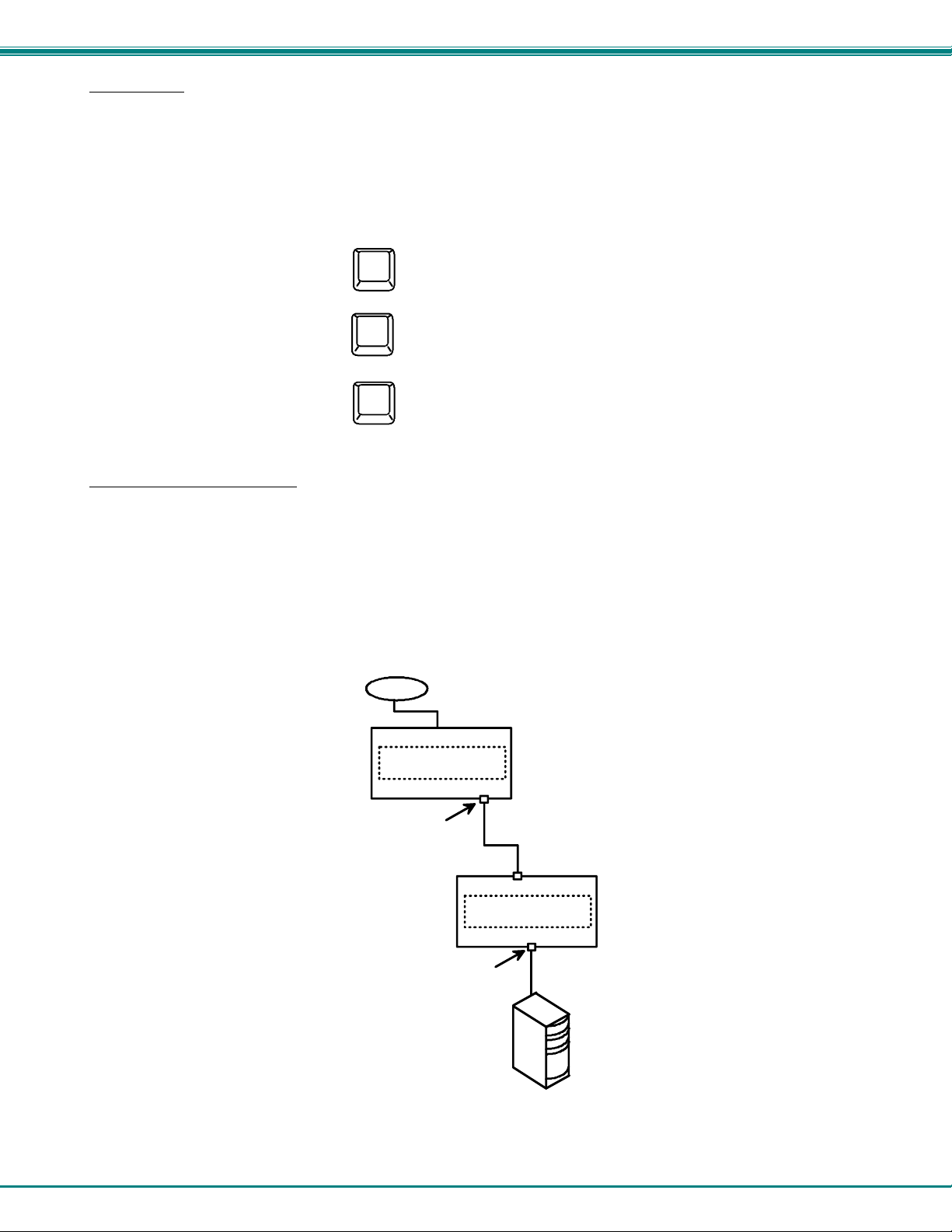
F3- Display Information
To display information about a selected port, pressing the <F3> key from within the Command Mode main menu will cause a
window to open. The window will show the name of the port and its position in the system structure, level by level. This is most
useful when cascading switches (for Cascading see page 33). An example of this structure might be
LEVEL 1 : PORT 5
LEVEL 2 : PORT 3
This means that the CPU connected through this port is actually connected through Port 5 of the master switch (Level 1), and
through port 3 of the slave connected to port 5 (Level 2). See Figure 27 below.
USER 1
USER PORTS
UNIMUX
MASTER
CPU PORT5
LEVEL 2
CPU PO RT 3
LEVEL 1
USER PORTS
UNIMUX
SLAVE
CPU PO RT S
CPU
Figure 27- Information provided by the F3 command
25
Page 30

NTI UNIMUX SERIES USB KVM SWITCH
RS232 CONTROL
(Optional)
RS232 enables the UNIMUX to be remotely controlled via RS232. To control the UNIMUX via RS232 the user has three options:
• write a program that runs on a PC using the Command Protocol (page 27)
• use the NTI Switch Control Program (page 29) provided on the CD
• use the SerTest program (page 29) provided on the CD
RS232 Connections and Configuration
Remote Connection
The RS232 Interface (optional) is designed to meet the RS232C standard and can be controlled from a ny CPU or other controller
with an RS232 communications port. The pin-out for the DB9 connector(s) on the unit is as follows:
RS232 CONNECTOR (DB9 FEMALE)
PIN SIGNAL FUNCTION
1 CD Carrier Detect
2 TXD Transmit data (RXD at host)
3 RXD Receive data (TXD at host)
4 DTR Data terminal ready
5 GND Signal ground
6 DSR Data set ready
7 RTS Request to send
8 CTS Clear to send
9 - No connection
Note: Security must be disabled or user access granted on th e port(s) to be selected by RS232 control.
On the DB9 female connector, pins 1 (DCD), 4 (DTR), and 6 (DSR) are shorted and pins 7 (RTS) and 8 (CTS) are shorted.
Therefore, host handshaking is bypassed and TXD and RXD are the only active signals. A straight through DB9 cable (not null
modem) will work for most CPUs (see page 38 for cable pinout) . To daisy chain multiple units, a Matrix Y-1 cable is used (see
page 27) for each UNIMUX in the chain. The last unit will have no connection on its output port and should hav e DIP switch 1 ON
(see table under "Unit Address and Loop Back" on page 27).
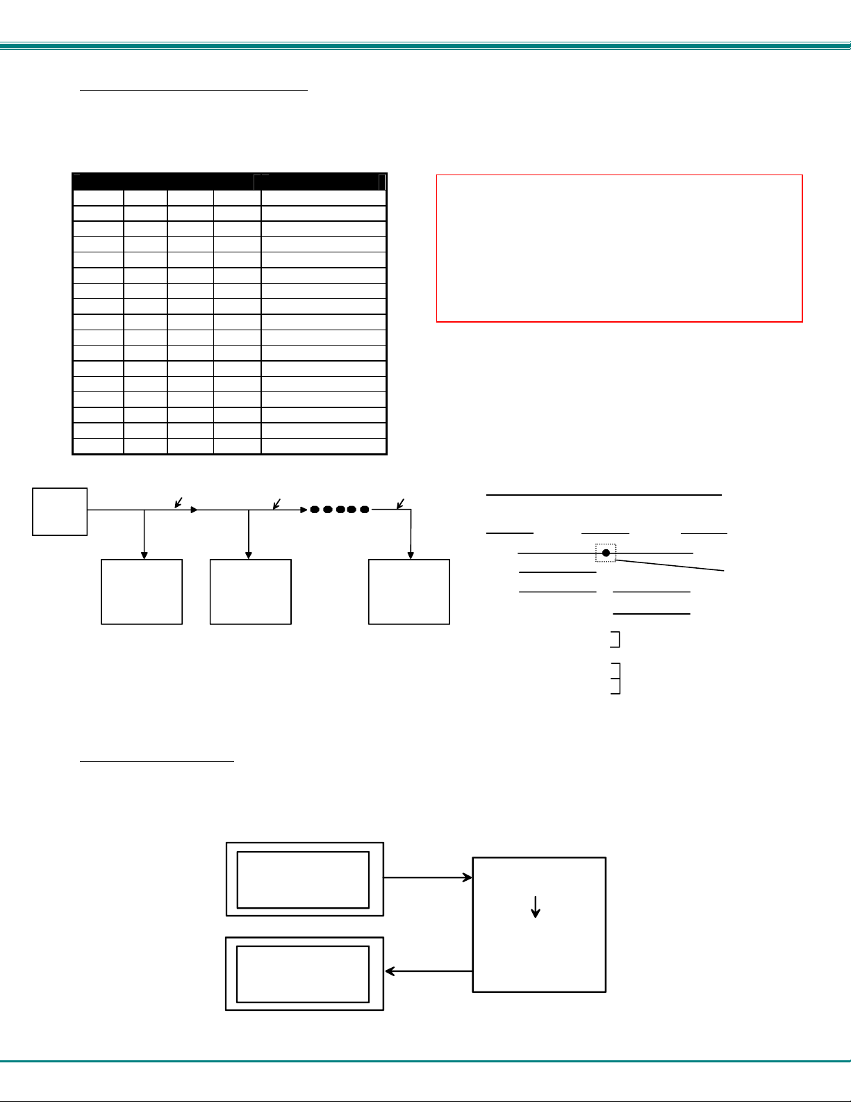
Baud Rate
The baud rate can be changed by powering down the unit, changing the 8 position RS232 DIP switch on the front of the UNIMUX,
and then powering back up. This table shows how to set the baud rate.
DIP SWITCH BAUD RATE
4 3 2
OFF OFF OFF 300
OFF OFF ON 600
OFF ON OFF 1200
OFF ON ON 2400
ON OFF OFF 4800
ON OFF ON
ON ON OFF
ON ON ON
9600
ON
OFF
(As seen on 4, 8,
16 and 32-port switch)
RS232
1 2 3 4 5 6 7 8
Figure 28- RS232 DIP switches
26
1 2 3 4 5 6 7 8
OFF
ON
RS232
(As seen on
2-port switch)
Page 31
NTI UNIMUX SERIES USB KVM SWITCH
Unit Address and Loop Back
To allow multiple units to be controlled from a single CPU serial port, the RS232 con trol interface is designed to allow "daisy
chaining" up to 15 units. By setting the appropriate RS232 DIP switches, each unit can be given a unique address (1-15). Then
the unit will only respond to commands on the bus if its address is embed ded in th e com mand. Us e the table below to set the un it
address.
DIP SWITCH UNIT ADDRESS
8 7 6 5
OFF OFF OFF OFF 0 (not valid)
OFF OFF OFF ON 1
Note: The "loop back" RS232 DIP switch (RS232 DIP
switch 1) should be ON for the last unit in the chain, and
OFF for all other units. If only one unit is being controlled,
the loop back DIP switch should be left ON.
OFF OFF ON OFF 2
OFF OFF ON ON 3
OFF ON OFF OFF 4
OFF ON OFF ON 5
OFF ON ON OFF 6
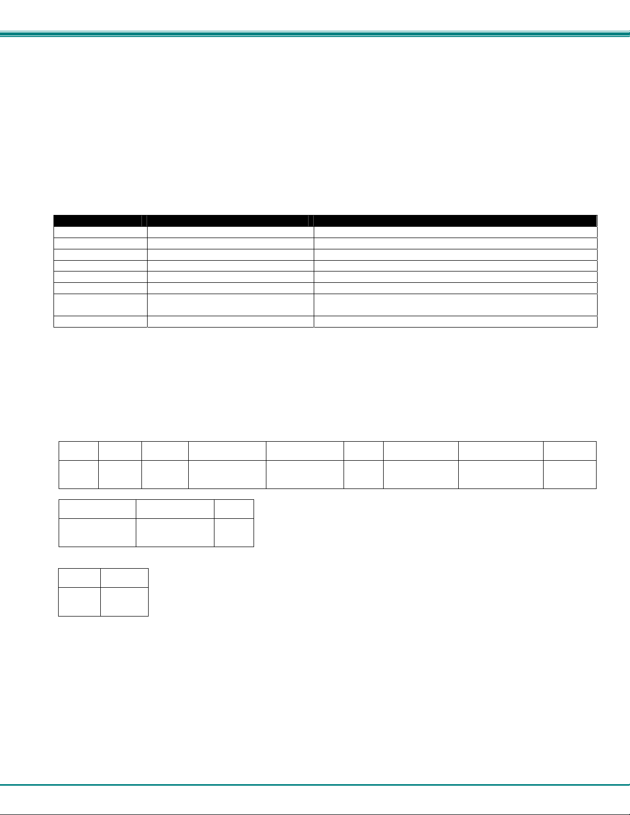
Note: In order to connect multiple UNIMUX units together
a Matrix-Y-1 cable must be used. (See Fig. 29.) See Fig.
30 for the pinout of the Matrix-Y-1 cable.
OFF ON ON ON 7
ON OFF OFF OFF 8
ON OFF OFF ON 9
ON OFF ON OFF 10
ON OFF ON ON 11
ON ON OFF OFF 12
ON ON OFF ON 13
ON ON ON OFF 14
ON ON ON ON 15
CPU
RS232
Serial Port
Matrix-Y-1
Matrix-Y-1 Matrix-Y-1
RS232
RS232
NTI
SWITCH
First Unit
NTI
SWITCH
Second Unit
Figure 29- RS232 connection with Matrix-Y-1 cable
RS232
NTI
SWITCH
Last Unit
Wiring Schematic of Matrix-Y-1 cable
(Unit #1)
23
33
555
9D Female9D Male 9D Male
(Source)
22
7
Jumper
8
1
Jumpers
4
6
(Unit #2)
Figure 30- Pinout of Matrix-Y-1 cable
Command Protocol
RS232 commands supported by the unit are defined below. All command strings should be terminated with a <CR> (carriage
return). When a command is sent, the entire string is echoed back along with a response from the addressed unit as shown in the
command definitions. All characters in the command string should be upper case, and all numbers below 10 should have a
leading 0 (ex: 1 = 01). As command strings are sent, the inner character delay cannot exceed 500 milliseconds.
(COMMAND SENT)
(RESPONSE RECEIVED)
CPU
CS 01,01,03<CR>
CS 01,01,03<CR>
* <CR>
RS232
RS232
SWITCH AT UNIT ADDRESS 01
(COMMAND RECEIVED)
CS 01,01,03<CR>
(ECHO)
CS 01,01,03<CR>
(RESPOND)
* <CR>
Not connected to
source conne c tor
Figure 31- RS232 Communication Illustrated
27
Page 32
NTI UNIMUX SERIES USB KVM SWITCH
Note: To use this command protocol, the user is required to write a program that will send an entire command string all
at once, not character by character. Programs that send one character at a time (such as HyperTerminal) cannot be used
to control the UNIMUX. Alternatively, the user may use the NTI Switch Control Program or SerTest to control the
UNIMUX via RS232 (see page 27).
Legend: (All numbers must be two digits)
SW : Switch (01-15) (Unit Address)
OP : Output (User) Port (01)
IP : Input (CPU) Port (01-MAXINPUTS)
<CR> : Carriage Return (Hex 0xD)
Note: For units with one output (user) port, use 01 for the output selection.
Command Definitions
Command String Good Response Description
CS SW,IP,OP *<CR> Connect Output (User) Port To specific Input (CPU) Port
RO SW,OP *<CR>IP<CR> Read Connection For Output (User) Port to Input (CPU) Port
RS SW *<CR> Internal Reset
RU SW *<CR>IP,OP<CR> Read Unit Size
SS SW,00 *<CR> Disable Autostatus feature (see below)
SS SW,01 *<CR> Enable Autostatus feature (see below)
GO SW,OP *<CR>go SW,OP:IP<CR> Read connection of an Output (User) Port to Input (CPU) Port
(different response format than RO command)
GM SW,00 *<CR>go OP,IP (all ports)<CR> Read connection matrix of all Output (User) ports
If the first field is not a known command (as listed above) or SW field is different from the unit address programmed at the DIP
switch (page 25), the command will be ignored. If the SW field corresponds to the unit address, but if the syntax is wrong after
this field, the switch will answer with a bad response ?<CR>.
Syntax example:
CS 01,05,01<CR> (insert the space and commas as shown)
which means “At the switch with unit address 01, connect CPU port 05 to user port 01”
The switch will answer with:
∗<CR>
The HEX code representation of example above is:
Byte 1 Byte 2 Byte 3 Byte 4 Byte 5 Byte 6 Byte 7 Byte 8 Byte 9
‘C’
(0x43)
‘S’
(0x53)
Space
(0x20)
Switch – 1st digit
(0x30)
Switch – 2nd digit
(0x31)
(0x2C)
Output – 1st digit
‘,’
(0x30)
Output – 2nd digit
(0x35)
(0x2C)
Byte 10 Byte 11 Byte 12
Input –1st digit
(0x30)
Response:
Input –2nd digit
(0x31)
<CR>
(0x0D)
Byte 1 Byte 2
‘∗’
(0x2A)
<CR>
(0x0D)
Autostatus
When Autostatus is enabled, any output (user) -to-input (CPU) connection change in the UNIMUX will cause an Autostatus
message to be sent via RS232 to the administrator. The format of the message would be "pc SW,OP:IP<CR>"
Example of an Autostatus message:
pc 01,01:04<CR>
which means "At the switch with unit address 01, the output (User) (01) has changed connection to input (CPU) port 04."
Note: An Autostatus message to the administrator will be delayed by any RS232 traffic being received by the switch
from the administrator.
By default, Autostatus is disabled and must be manually enabled.
‘,’
28
Page 33

NTI UNIMUX SERIES USB KVM SWITCH
NTI Switch Control Program For Windows 9X, NT, 2000, Vista and 7
The NTI Switch Control Program is an easy and powerful graphical program that controls NTI switches through an RS232
interface. The NTI Switch Control Program is included on the CD packaged with the UNIMUX. The NTI Switch Control
Program is downloaded by clicking on the link "Download NTI Switch Control Program".
To install the NTI Switch Control Program after downloading
1. Locate the Setup.exe in the directory the program was downloaded to and double-click on it
2. Follow the instructions on the screen
The NTI Switch Control Program performs best on monitors set to a screen resolution of at least 800 X 600. Instruction for using
the NTI Switch Control Program is available by opening "MSCP Help" in the "NTI" program group once the program has been
installed and is open on the screen.
To open "MSCP Help" from the Windows desktop
1. Click on START
2. Click on PROGRAMS
3. Click on NTI
4. Click on MSCP Help
SerTest- RS232 Interface Test Program
This software allows a user to test the functions of an NTI server switch, matrix switch or Multi-user/Multi-platform/Single-user
switch RS232 interface. The SerTest program is automatically loaded when installing the NTI Switch Control Program as
described above. The SerTest program, located in the NTI program group, generates a main menu with the 4 selections
described below:
Main Options
• Switch Operations
• Ethernet Operations
• Setup Options
• About SerTest
If Matrix Operations is selected, the following menu is displayed:
SWITCH OPERATIONS
1) Reset Unit
- send a reset command to the switch
- the current unit address is displayed in parentheses
2) Reset All Units
- send an internal reset command to all switches
3) Connect Output/User to an Input/CPU
- connect an output to an input
4) Connect All Outputs/Users to an Input/CPU (not applicable to this model)
- connect all outputs to an input
5) Connect Audio Output/User to an Input/CPU (not applicable to this model)
- connect an output to an input
6) Connect All Audio Outputs/Users to an Input/CPU (not appli c able to this model)
- connect all outputs to an input
7) Change Mute Status for Audio Output/User (not applicable to this model)
- mute or un-mute the Audio port output
8) Change Volume for Audio Output/User (not applic able to this model)
- change Audio port output volume
- send commands to the unit.
- set Ethernet connection variables (not applicable to this model)
- set COM port, baud rate, and unit address
- display the program version
29
Page 34

NTI UNIMUX SERIES USB KVM SWITCH
9) Read Connection for Output/User
- read what input is connected to the specified output
a) Read Connection for Audio Output/User (not applicable to this model)
- read what input is connected to the specified output
b) Read Mute Status and Volume for Audio Output/User (not applicab le to this model)
- read the volume and the mute status of the specified output
c) Read Unit Size
- read the switch size (number of inputs and outputs)
d) Read Unit Version/Revision String (not supported by this mode l)
- read a string containing the switch version, type, and size
e) Save I/O Connections into Unit Memory (not applicable to this model)
- save the connections into switch memory bank
f) Restore I/O Connections from Unit Memory (not applicable to this model)
- restore the connections from switch memory bank
g) Save All Units I/O Connections into Units Memory (not applicable to this model)
- save the connections into switch memory bank, command for all switches
h) Restore All Units I/O Connections from Units Memory (not applicable to thi s model)
- restore the connections from switch memory bank, command for all switches
i) Change All Units Baud Rate (9600/COM1) (not applicable to this model)
- change RS-232 Baud rate of all switches
- the current baud rate and serial port are displayed in parentheses
ETHERNET OPERATIONS (not applicable to this model)
SETUP OPTIONS
1) Select Com port current: (COM1:)
- select PC serial port
- the current PC serial port is displayed in parentheses
2) Select Baud rate current: (9600)
- select PC serial port baud rate
- the current baud rate is displayed in parentheses
3) Set unit Address current: (1)
- select the unit address of the switch to be connected to by this program
- the current address is displayed in parentheses
For any selection that requires user input, the user is prompted. When commands are sent to the UNIMUX, the command string
and UNIMUX responses are echoed to the screen. All commands generated by the program are formatted according to the
information provided in sections above. If any transmission problems are detected, an error message is displayed.
Press <Esc> o
r <Enter> to back out to the main menu and press again to exit.
30
Page 35
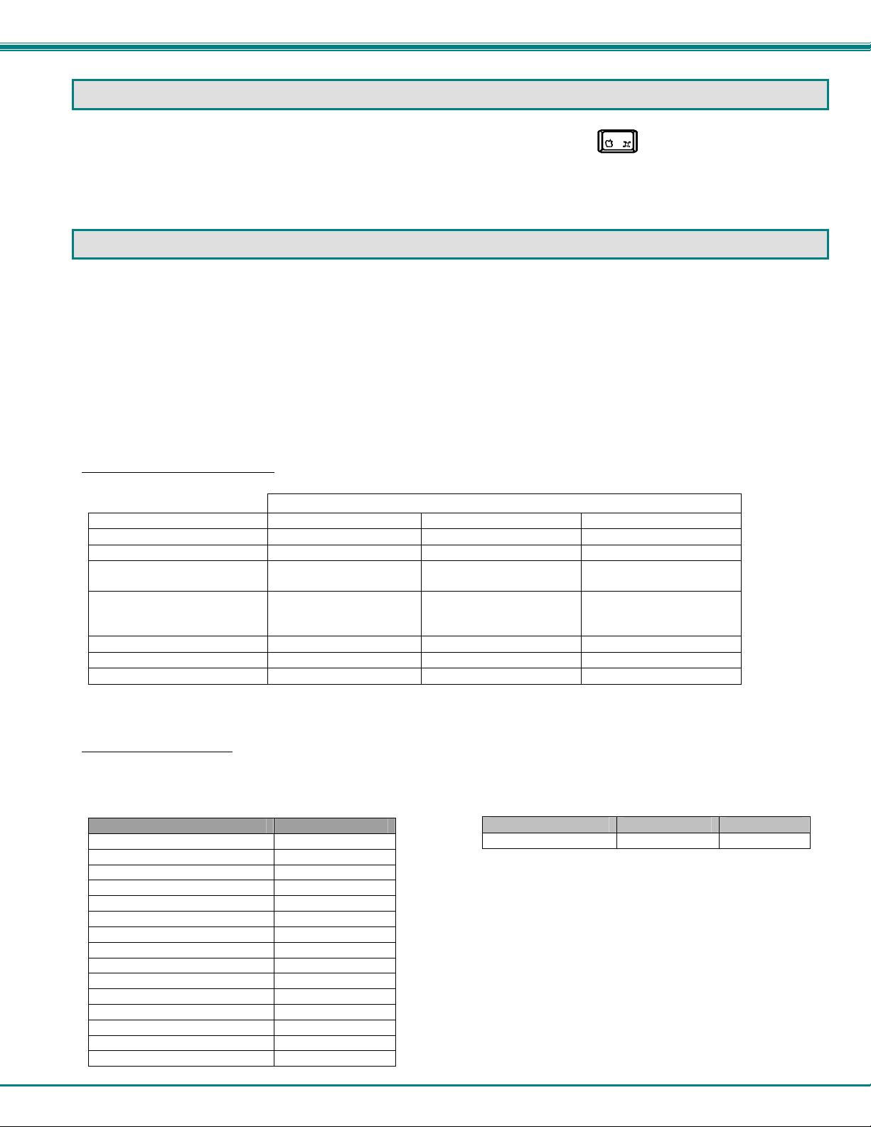
NTI UNIMUX SERIES USB KVM SWITCH
MOUSE CLICK EQUIVALENTS
To emulate a right button click using Apple 1 button mouse, hold down the Command key ( ) while pressing the mouse
button.
Note: Right mouse button emulation must be enabled (see Change Settings on page 19) for this to work.
KEYBOARD FEATURES
The keyboard configuration of each CPU is saved in the UNIMUX. For example, if the CPU attached to Port 2 had CAPS LOCK
and NUM LOCK selected the last time that CPU was accessed, then they will automatically be set when that CPU is accessed
again.
Keyboard-To-Computer Translation
The UNIMUX enables a mixture of otherwise incompatible peripheral computer components to be connected together. This is
accomplished by performing keyboard-to-computer translations automatically (i.e. translate a MAC keyboard and mouse to a
Windows type CPU). The chart below shows the capabilities of devices controlling certain CPU types.
Translation Capabilities
CPU
Device Sun Mac Windows
Sun Keyboard
AT101 Keyboard
Mac keyboard
Apple Pro Keyboard
Sun Mouse
Wheel Mouse
Apple Mouse
Translation Tables
Use the charts below to type SUN’s additional keys with Win95 and Apple keyboards:
SUN Extra Keys
WINxx or Mac Keyboards Sun Extra Keys
Space Bar + F1 Stop
Space Bar + F2 Again
Space Bar + F3 Props
Space Bar + F4 Undo
Space Bar + F5 Front
Space Bar + F6 Copy
Space Bar + F7 Open
Space Bar + F8 Paste
Space Bar + F9 Find
Space Bar + F10 Cut
Space Bar + F11 Help
Space Bar + F12 Compose
Space Bar + Up Arrow Volume +
Space Bar + Down Arrow Volume Space Bar + Left Arrow Mute
Full functionality Full functionality Full functionality
Extra keys emulation Power key emulation Full functionality
Extra keys emulation Full functionality Full functionality-except
Extra keys emulation Extra Keys not supported
(Eject, Mute, Volume+,
Volume-)
Full functionality Full functionality Full functionality
Full functionality Full functionality Full functionality
Right button emulation Full functionality Right button emulation
(See Fig. 32 on page 32 for reference.)
Application Key
Full functionality
Power Key Emulation
Win95 Keyboards Mac CPU Sun CPU
SB+RT Arrow Power Power
Mouse Click Equivalents
To emulate right-button click using an Apple 1-button
mouse, hold down the CMND key (key with open
apple insignia) while pressing the mouse button.
31
Page 36

NTI UNIMUX SERIES USB KVM SWITCH
Esc
~
`
Tab
Caps Lock
Shift
Ctrl Alt
Esc
F1 F2 F3 F4 F5 F6 F7 F8 F9 F10 F11 F12
~
`
Tab
Caps Lock
Shift
Ctrl Alt
Windows Logo Key
Help
Stop
Props
Front
Open
Find Cut
Again
Undo
Copy
Paste
esc
~
`
tab
caps Lock
shift
control
alt
option
Esc
Tab
Control
Shift
Capslock Alt
Command Key
Apple Pro USB Keyboard
Meta Key Meta Key
Backspace
Enter
Shift
Ctrl
Alt
Typical 101 Ke yboard
Backspace
Enter
Shift
Alt
Ctrl
Application KeyWindows Logo Key
Windows USB Keyboard
F12 F11
F10 F8 F7 F6 F5 F4 F3 F2 F1
F9
delete
return
shift
alt
controloption
Command Key
Backspace
Return
Shift
Compose
SUN USB Keyboard
Print
Screen
SysRq
F13 F14 F15
Alt
Graph
Scroll
Lock
Pause
Break
Num
Lock
Num
Lock
num
lock
clear
=/
Num
Lock
Enter
Enter
*
enter
CD Eject
Key
Enter
Power
key
Figure 32- Keyboard Layouts
International Sun Keyboards
The UNIMUX can recognize international layouts for Sun keyboards. In order to use an international Sun keyboard, follow this
procedure:
1. Power-OFF the CPU from the UNIMUX
2. Connect the international keyboard to be used to the UNIMUX
3. Power-ON the CPU to the UNIMUX
It is also possible to configure the UNIMUX to emulate a specific international Sun keyboard regardless of what actual keyboard is
connected. This is recommended when the CPU needs the layout code (i.e. a SUN CPU) and the keyboard doesn't have an
explicit layout code (i.e. some Windows keyboards). To do this, manually set the UNIMUX to indicate the international keyboard
identification number to the CPU by following the instruction on page 9 (for switches without OSD feature) or on page 19 (for
switches with OSD feature).
32
Page 37
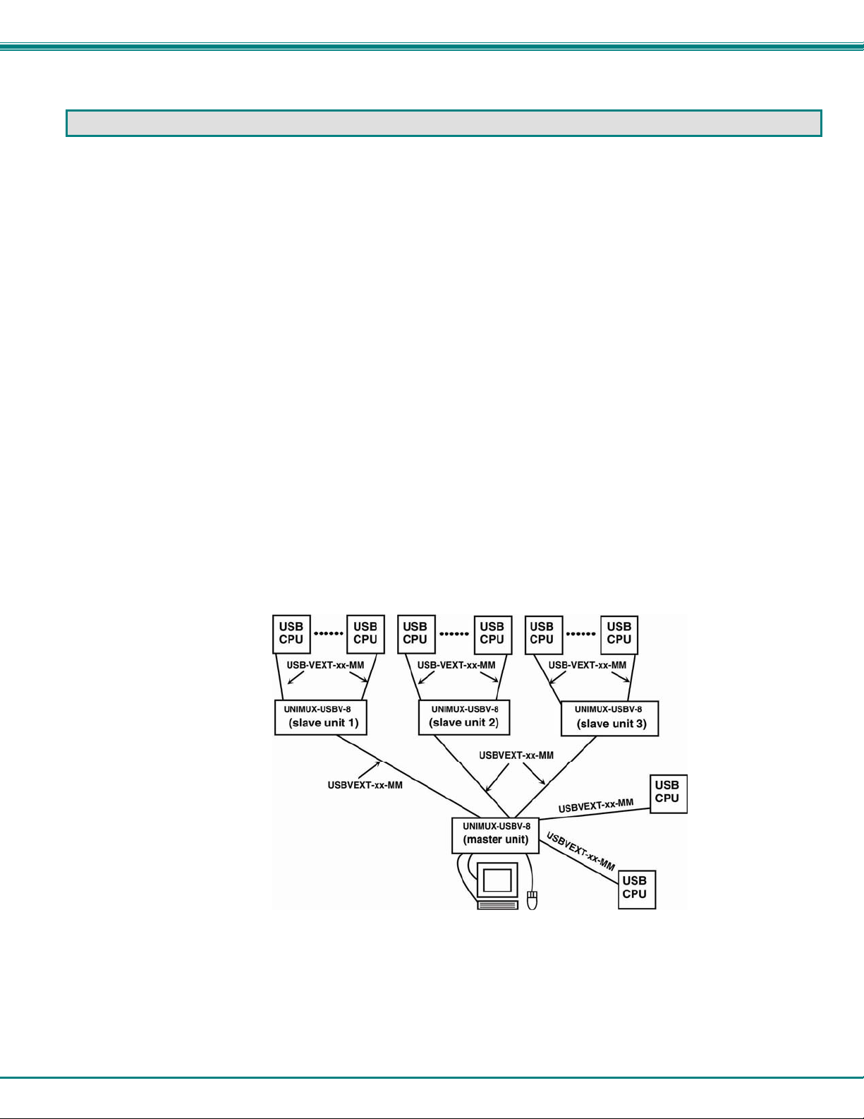
NTI UNIMUX SERIES USB KVM SWITCH
CASCADING
The UNIMUX-USBV-x USB KVM switch can be cascaded as shown in Fig. 33 below. Single user and multi-user UNIMUX
switches may be connected downstream (see Figs.35 and 36). The first switch in a cascaded system is referred to as the
"master", while all downstream switches are referred to as "slaves". The only additional hardware requir ed to cascade switches is
a set of device and monitor cables for each “SLAVE UNIT” (see MATERIALS on page 1). All CPUs and switches can then be
controlled by users using OSD commands with Command Mode.
Notes:
• Cascading is not an option in the UNIMUX-USBV-2 2 port USB KVM switch
• Slaves in a cascaded system must be either all single-user switches or all multi-user switches, but not a
combination of both.
Configuration
In a cascaded system no additional configuration is necessary.
Cascaded Installation
a. Using the 15HD video cable ends of a USBVEXT-xx-MM cable, connect the USB KVM slave's MONITOR port to the master’s
VIDEO 1 port.
b. Using the USB ends of the same USBVEXT-xx-MM cable, connect one of the USB slave’s USB DEVICES ports to the
master’s CPU 1 port.
Note: Only one of the two ports labeled DEVICES on a slave needs to be used in order for cascading to work.
c. Repeat step a. & b. for each additional slave, keeping in mind that each slave will connect to the next available master’s
port (i.e. Slave #2 to master’s VIDEO 2 & CPU 2, etc.) See Fig. 35 on page 35.
d. IMPORTANT: Power On each of the slave units first, THEN the master switch. (Whether the CPUs are powered-ON or not
doesn’t matter, but the UNIMUX slaves must be powered-ON first.)
Figure 33- Connections for Cascading
.
33
Page 38

NTI UNIMUX SERIES USB KVM SWITCH
USBVEXT-xx-MM
(USER
PORT 1)
USER PORTS
UNIMUX-4X8
SLAVE
CPU PO RTS
USBVEXT-xx-MM
(8 CABLES)
CPU1 CPU 8
Figure 34- Cascaded configuration with multi-user slaves
FYI: Any USER and MONITOR ports on a multi-user switch connected as a slave that do not get connected to the master
can be connected to by users (for example users 5-8 in Fig. 30). Users co nnected to a slave downstream from the
master will control only the CPUs directly connected to that slave switch (i.e. users 5 and 6 in Fig. 34 above can only
control CPUs 25-40).
NETWORK TECHNOLOGIESINC Tel:330-562-70701275 Danner Dr, Aurora, OH 44202 w ww.nti1.com
USER 1
USER PORT
UNIMUX-1X4
MASTER
CPU PORTS
(TO USE R P O RT 2 O N
SLAVES 1-4)
USBVEXT-xx-MM
(USER
PORT 1)
SLAVE #2 (UNIMUX-USBV-8-RS)
CPU 8
CPU 6 CPU 5
CPU 7
R
S
2
CPU 4CPU 3CPU 2CPU 1
3
2
USB DEVICES
MONITOR
8 4 7 3 6 2 5 1VID EOVIDEO
USER 2 USER 3 USER 4
USER PORT
UNIMUX-1X4
MASTER
CPU PORTS
USER PORTS
UNIMUX-4X8
SLAVE
CPU PORTS
USBVEXT-xx-MM
(8 CABLES)
CPU9 CPU 16
USER PORT
UNIMUX-1X4
MASTER
CPU PO RTS
(TO USER PORT 3 O N
SLAVES 1-4)
USBVEXT-xx-MM
(USER
PORT 1)
USER PORTS
UNIMUX-4X8
SLAVE
CPU PO RTS
USBVEXT-xx-MM
(8 CABLES)
CPU17
UNIMUX-1X4
(TO USER PORT 4 ON
SLAVES 1-4)
CPU 24
MASTER (UNIMUX-USBV-8-RS)
CPU 8CPU 7CPU 6CPU 5
R
S
2
CPU 4 CPU 3 CPU 2 CPU 1
3
NETWORK TECHNOLOGIESINC Tel:330-562-70701275 Danner Dr, Aurora, OH 44202 www.nti1.com
2
USB DEVICES
MONITOR
8 4 7 3 6 2 5 1
USBVEXT-xx-MM
CPU 8
R
S
2
CPU 4 CPU 3 CPU 2 CPU 1
3
NETWORK TECHNOLOGIESINC Tel:330-562-70701275 Danner Dr, Aurora, OH 44202 www.nti1.com
2
USER PORT
MASTER
CPU PO RTS
USBVEXT-xx-MM
(USER
PORT 1)
Users 5-8 only have access to CPUs 25-40.
Users 1-4 have access to all CPUs
USER 5
USER PORTS
UNIMUX-8X16
SLAVE
CPU PO RTS
USBVEXT-xx-MM
(16 CA BLES)
CPU 25 CPU 40
VIDEOVIDEO
USBVEXT-xx-MM
SLAVE #1 (UNIMUX-USBV-8-RS)
CPU 6 CP U 5
CPU 7
USB DEVICES
8 4 7 3 6 2 5 1
MONITOR
USER 6
USER 7
VIDEOVIDEO
USER 8
Figure 35- Master-to-slave device cable connections- single-user switches
34
Page 39
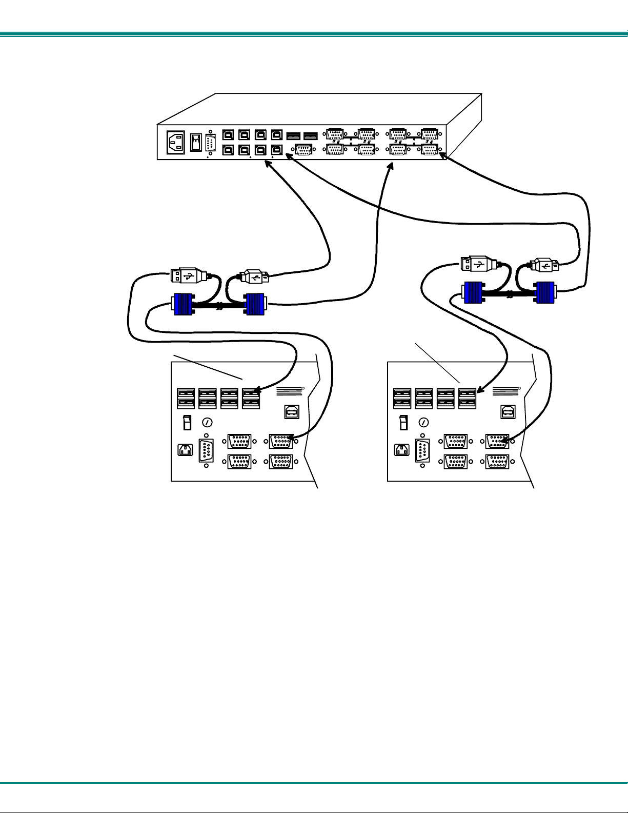
NTI UNIMUX SERIES USB KVM SWITCH
CONNECT MASTER CPU PORT 2
ONE USER PORT ON SLAVE2
NETWORK TECHNOLOGIESINC Tel:330-562-70701275 Danner Dr, Aurora, OH 44202 www.nti1.com
R
S
2
3
2
USBVEXT-xx-MM
USER 3USER 4
R
S
2
3
2
SLAVE #2 UNIMUX 4X16 SLAVE #1 UNIMUX 4X16
REAR VIEW OF MASTER (UNIMUX-USBV-8O-RS)
CPU 8CPU 7CPU 6CPU 5
CPU 4 CPU 3 CP U 2 CP U 1
USER 1USER 2
NTI
MONITOR 3
MONITOR 4
MONITOR 1
MONITOR 2
USB DEVICES
CPU 16
MONITOR
8 4 7 3 6 2 5 1
CONNECT MASTER CPU PORT 1
TO ONE USER PORT ON SLAVE1
R
VIDEOVIDEO
USBVEXT-xx-MM
R
S
2
3
2
USER 1USER 2
MONITOR 3
MONITOR 4
NTI
CPU 16
MONITOR 1
MONITOR 2
R
USER 3USER 4
Figure 36- Master to slave cable connections- multi-user switches
Limitations
¾ Up to 8 slaves may be connected to form a maximum system size of 152 ports (1x32 port master + 8x16 port slaves).
¾ Slaves must be added to the master in order (slave #1 to master’s port 1, slave #2 to master’s port 2, etc).
FYI: Master Port 1 (with an 8-port Slave connected to it) will become ports 1-8 (1-4 for a 4-port slave). Master Unit Port 2
(with a second 8-port Slave Unit connected) will become port numbers 9-16 (5-8 for a 4-port slave).
¾ The front panel buttons are only used to operate standalo ne switches. T o control a cascaded network of switches, only the
OSD commands within Command Mode will be recognized.
Note: Cascading is not an option in the UNIMUX-USBV-2 2 port USB KVM switch.
35
Page 40
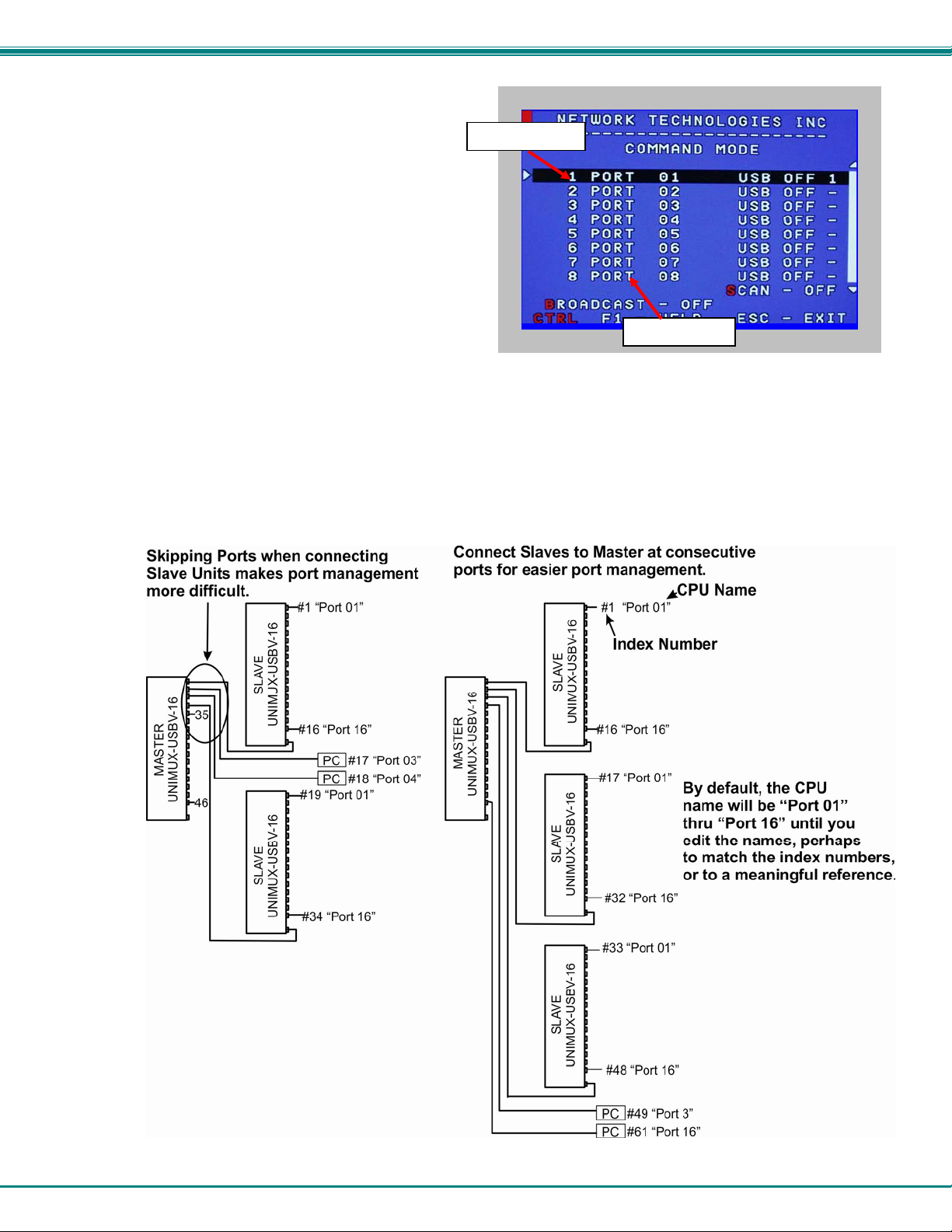
NTI UNIMUX SERIES USB KVM SWITCH
I
Port Assignments in OSD
When the Master powers up with the powered-ON
Slave switches connected, you will need to enter
Command Mode (page 12) to view the updated port list.
Port Identification Rules:
1. Index numbers will always follow the
number of CPU ports connected, consecutively
as they are presented by the switches.
For example, with three 1x16 slaves connected to
a 1x16 Master, you will have:
Index numbers 1-16 assigned to ports for the switch
connected to Master port 1.
Index numbers 17-32 assigned to ports for the switch
connected to Master port 2,
Index numbers 33-48 assigned to the ports for the switch
connected to Master port 3.
The CPUs connected to Master ports 4 thru 16 in this scenario would then have Index numbers 49-61.
2. Port names, by default, will follow the switches they are attached to. If you connect three 1x16 slaves, you will have three
ports named “Port 01”, three named “Port 02”, three named “Port 03”, and so on. (See below.)
For this reason, when connecting Slave switches to a Master switch, we recommend that Slaves be connected
to consecutive ports (the first to Master port 1, the second to Master port 2, and so on). Once they are connected, renaming the
ports to something meaningful for the switches they pertain to will help keep their identities/locations easier to remem ber in the
Command Mode list.
ndex Number
CPU Name
Figure 37- Slave Port Identification
36
Page 41
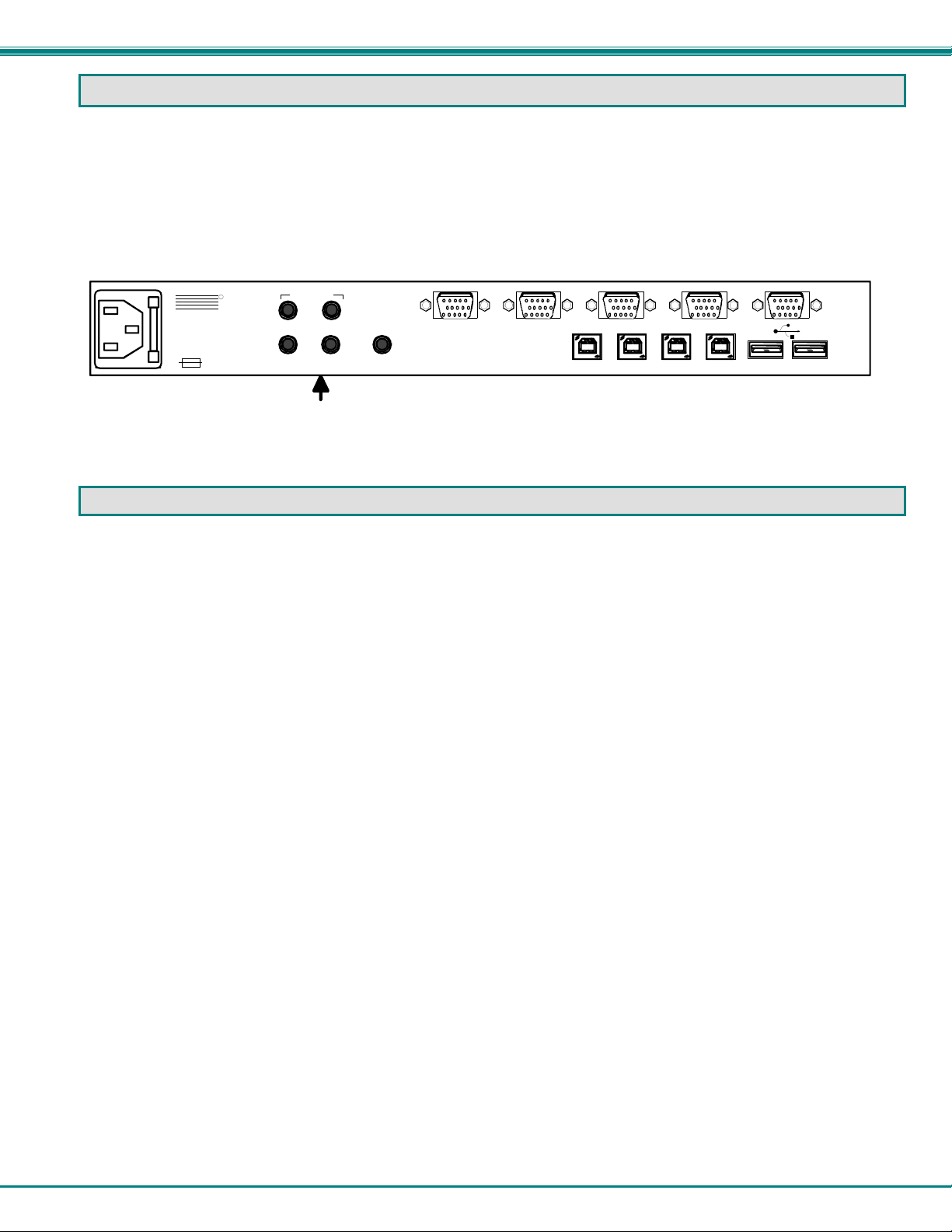
NTI UNIMUX SERIES USB KVM SWITCH
AUDIO SUPPORT
(Optional)
Models with audio support include 3.5mm stereo jacks for conn ection to audio sources and an output device. Audio from either
the same sources as the video, keyboard, and mouse or from separate sources (any standard line level audio (4Vp-p)) will be
heard through devices such as self-powered stereo speakers or headphones.
Audio signals are switched along with the keyboard, mouse and video signals using the buttons on the UNIMUX switch.
Connections to “AUDIO IN” ports will switch at the same time as like-numbered “VIDEO” and “CPU” ports when controlling the
switch. For example, if “VIDEO 1” is switched to “VIDEO 2”, then “AUDIO IN 1” will also switch to “AUDIO IN 2”.
R
NTI
1275 Danner Dr
Aurora, OH 44202
www.networktechinc.com
NETWORK
TECHNOLO GIES
INCORPORATED
Tel:330-562-7070
Fax:330-562-1999
250V,2A
AUDIO IN
(CPU)
34
12
AUDIO OUT
(USER)
VIDEO 4
3.5mm Stereo Jacks
Figure 38- Rear View of UNIMUX-USBV-4O-A
TROUBLESHOOTING
PROBLEM:
SOLUTION:
PROBLEM:
SOLUTION:
PROBLEM:
SOLUTION:
SOLUTION:
PROBLEM:
SOLUTION:
PROBLEM:
SOLUTION:
SOLUTION:
PROBLEM:
SOLUTION:
SOLUTION:
SOLUTION
SOLUTION
Keyboard Errors
Check cable connections on each CPU and the switch.
No Video
Check cable connections on each CPU and the switch. Verify that keyboard and video connect from each CPU
to matching ports. After reconnecting, CPU may need to be re-booted in order to sense the monitor connection.
No Mouse Movement
Check cable connections of mouse. Verify that mouse driver was loaded.
Broadcast Mode is ON. Turn OFF Broadcast Mode.
Front pushbuttons are not working
Unit in Security mode. User not authorized to access switch. Log-in with authorized name and password.
No RS232 communication
Using null modem cable. Change cable to straight-through type (see page 38).
DIP switch settings are not correct for computer baud rate. Set DIP switches to desired baud rate and power
cycle the switch (see page 26).
No keyboard and mouse
Unit is in Command Mode. Press <Esc> key until Command Mode LED on UNIMUX is OFF
USB lock-up- Hot plug the keyboard and mouse
USB lock-up- Hot plug the USB cable from the computer
UNIMUX lock-up- Power cycle the UNIMUX switch
VIDEO 3 VIDEO 2 VIDEO 1 MONITOR
CPU 4 CPU 3 CPU 2 CPU 1
37
Page 42

NTI UNIMUX SERIES USB KVM SWITCH
RS232 CONNECTION CABLES
Pinout of RS232 port on UNIMUX
The UNIMUX RS232 serial port is a DB-9F (female) connector configured as a DCE (data communication equipment) port. The
RS232 port interface signals are listed below, including equivalent CCITT V.24 identification, and signal direction:
DB-9F
pin #
1 N/a N/a N/a No connection -2 TxD BA 103 Transmit Data Output
3 RxD BB 104 Receive Data Input
4 DSR CC 107 Data Set Ready Input
5 SG AB 102 Signal Ground –
6 DTR CD 108.2 Data Terminal Ready Output
7 CTS CB 106 Clear To Send Input
8 RTS CA 105 Request To Send Output
9 N/a N/a N/a No connection --
Common
name
EIA
name
CCITT
name
Function Direction
Specifications for Straight-Through Serial Cable for CPU Connection
UNIMUX to PS2 or SUN CPU (9 PIN) UNIMUX to MAC CPU (25 PIN)
UNIMUX PS/2 or SUN CPU UNIMUX MAC CPU
9 pin Signal 9 pin 9 pin Signal 25 pin
Function Pin # Direction Pin # Function
RxD 3 3 TxD RxD 3 2 TxD
TxD 2 2 RxD TxD 2 3 RxD
CTS 7 7 RTS CTS 7 4 RTS
RTS 8 8 CTS RTS 8 5 CTS
DSR 4 4 DTR DSR 4 20 DTR
DTR 6 6 DSR DTR 6 6 DSR
SG 5 5 SG SG 5 7 SG
UNIMUX
9 PIN
DTE
9 PIN
DTE
PS/2 or SUN CPU
1
2345
6
8
7
9
Mating Face
of a 9D Male
1
14 15
Function Pin # Direction Pin # Function
9 PIN
UNIMUX
345
2
16
17
18
6
19 20
DTE
89
7
21 22 23 24 25
Mating Face of DB25 Male
10
25 PIN DT E
13
1211
MAC CPU
38
Page 43

NTI UNIMUX SERIES USB KVM SWITCH
INDEX
administration mode, 14
administrator login, 12
alternate command hot key, 16
Audio support, 37
basic command mode, 9
baud rate, 26
Broadcast Mode, 19
cascading, 33
change administrator password, 14
Change Settings, 21
control methods, 8
default password, 12
devices supported, 1
display information, 25
edit user, 15
features, 3
front panel control, 8
Help Mode, 25
installation, 5
international layouts, 32
keyboard configuration, 31
keyboard control, 8
limitations, 7
MAC Ports Configuration, 22
Maintenance Mode, 24
NTI Switch Control Program, 29
options available, 1
OSD command mode, 12
Rack mounting, 4
RS232, 26
RS232 cable, 38
RS232 commands, 27
Scan Mode, 19
Search Mode, 23
Security option, 12
Select La
nguage, 22
Select Ports For Broadcasting, 21
Select Ports For Scanning, 22
SerTest, 29
SUN’s additional keys, 31
unit address, 27
usage statistics, 17
user access functions, 18
user login, 13
user name list, 15
WARRANTY INFORMATION
The warranty period on this product (parts and labor) is two (2) years from the date of purchase. Please contact Network
Technologies Inc at (800) 742-8324 (800-RGB-TECH) or (330) 562-7070 or visit our website at
http://www.networktechinc.com/return-policy.html for information regarding repairs and/or returns. A return authorization number
is required for all repairs/returns.
MAN035 Rev 2/12/13
39
 Loading...