

Page 1
INSTALLATION GUIDE FOR THE
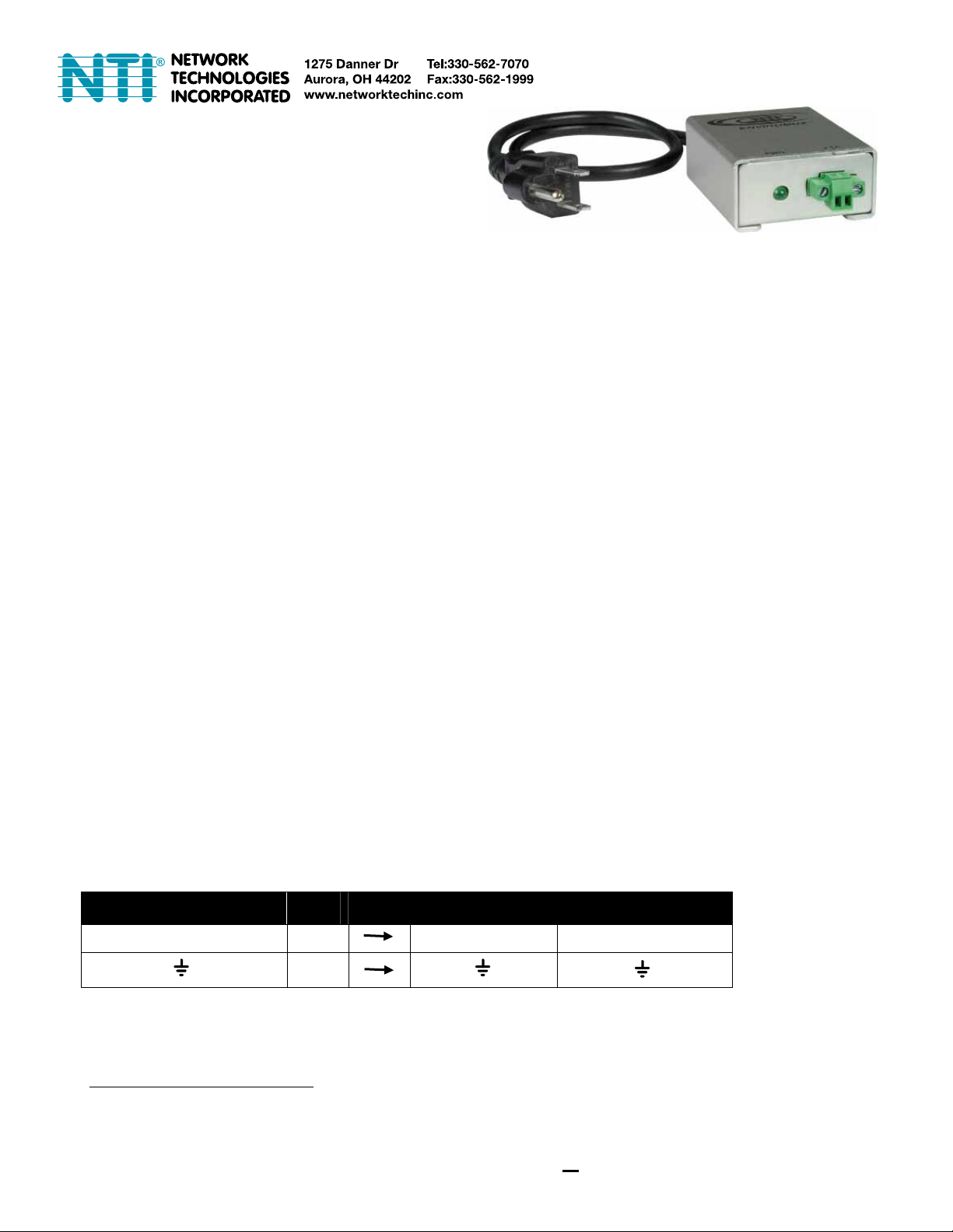
AC Voltage Detector
ENVIROMUX-ACVD-xxx
INTRODUCTION
The NTI ENVIROMUX-ACVD-xxx detects voltage (70-250VAC) when connected to an ENVIROMUX-SEMS-16 or ENVIROMUXMINI. A 2-wire sensor cable (6 foot cable included), is used to connect to an ENVIROMUX, which can be configured to send
alerts based on the presence or lack of AC voltage.
Models available:
ENVIROMUX-ACVD-515 – For use with ENVIROMUX-SEMS-16
ENVIROMUX-ACVD-515M – For use with ENVIROMUX-MINI (SEE NOTE BELOW)
ENVIROMUX-ACVD-C14 – For use with ENVIROMUX-SEMS-16 but with universal 250V IEC C14 socket
ENVIROMUX-ACVD-C14M – For use with ENVIROMUX-MINI but with universal 250V IEC C14 socket
Note: The ENVIROMUX-ACVD-515M and ENVIROMUX-ACVD-C14M are only compatible with ENVIROMUX-MINI units
made on or after 11/1/07 (see label on the bottom of your ENVIROMUX-MINI). If your ENVIROMUX-MINI was made prior
to 11/1/07, please order model ENVIROMUX-ACVD-515 or ENVIROMUX-ACVD-C14. Failure to use the correct voltage
detector will result in inaccurate alert reports.
Features:
¾ Monitors the presence of 70-250VAC
¾ 2-position screw-terminal connection
¾ Supports 2-wire sensor cable up to 1000 ft
1
(6 foot cable included)
¾ RoHS and CE certified
MATERIALS SUPPLIED
¾ ENVIROMUX-ACVD-xxx Power Monitor (xxx= 515,515M,C14, or C14M)
¾ ENVIROMUX-2W-6 (6 foot 2-wire sensor cable)
¾ Installation Guide
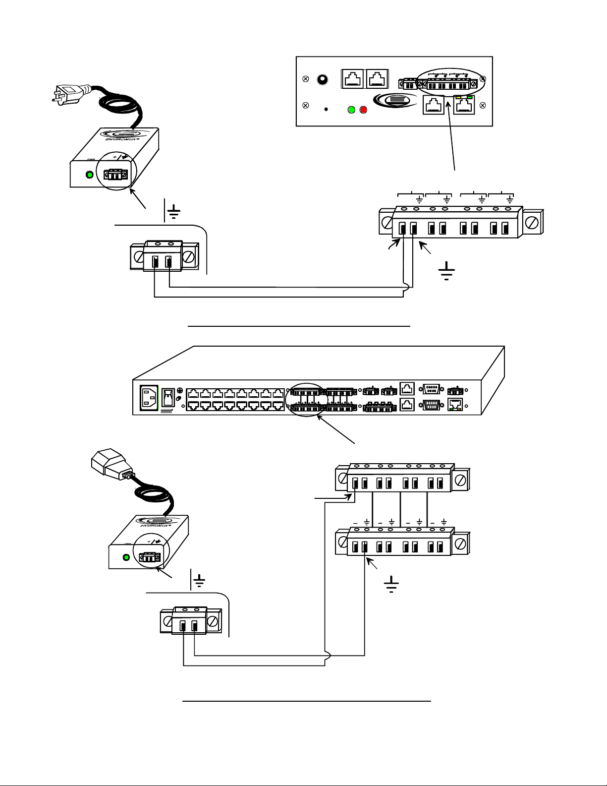
INSTALLATION
Place the ENVIROMUX-ACVD-xxx where it can be plugged into an AC po wer source (70-250VAC). Connect a 2-wire cable
between the terminals on the ENIVROMUX-ACVD-xxx and the “CONTACTS” terminals on the ENVIROMUX-MINI, or the
“DIGITAL IN” terminals on the ENVIROMUX-SEMS-16
2
.
Use the chart below or see images on next page to make proper wire connections:
TERMINAL ON
ENVIROMUX-ACVD-515
+
Wire
Color
White
Black
TERMINAL ON
ENVIROMUX-MINI
+5V
TERMINAL ON
ENVIROMUX-SEMS-16
+
3
1
When using 2-wire cables longer than 100 ft, be careful to route cables away from AC wiring, lighting sources, electric motors, or
other electrical devices.
2
The wire connection terminal blocks are easily removed from the ENVIROMUX-ACVD-xxx, ENVIROMUX-MINI, and
ENVIROMUX-SEMS-16 for more convenient wire termination.
3
In the event that the ground terminal is unavailable, the negative terminal ( ) has the same potential and can be substituted.
1
Page 2
Front View of ENVI R OM U X-MINI
TEMPERATURE / HUMIDITY
5V
2.0A
PWR
WATER CONTACTS
SENSE SENSE
R
NTI
Network Technologies Inc
ENVIROMUX
AREA ALERT
TM
TM
12 34
+5V
+5V +5V +5V
RS232 ETHERNET FAULT
ENVIROMUX-ACVD-515(M)
+
CONTACTS
12
+5V
+5V +5V +5V
3
4
black wire
white wi r e
Wire connections for ENVIROMUX-MINI
white wi r e
+5V
black wire
R
NETWORK TE CHNOLOGI ES INC Tel:330 -562-707 01275 Danner Dr, Aurora, OH 44202 www.networktechinc.com
NTI
REAR VIEW OF ENVIROMUX-SEMS-16
RJ45 SENSORS
DIGITAL IN
1 234 56 78
+ 12V + 12V + 12V + 12V
BEACON SIREN
+12V
+12V
OUTPUT RELAYS
1234
AUX
AUX PWR
+12V+ 12V + 12V + 12V + 12V
OUT
CONSOLE
IN
ETHERNET
1234
+ 12V + 12V + 12V + 12V
white wire
+
ENVIROMUX-ACVD-C14
+
black wire
Wire connections for ENVIROMUX-SEMS-16
black wire
white wi r e
2
Page 3

The ENVIROMUX-ACVD-xxx can also be connected to the “RJ45 SENSORS” sockets. When using a CAT5 patch cable to make
connection, you must first determine what wiring standard the cable has been made to. Make connections based on the chart
below.
TERMINAL ON
ENVIROMUX-ACVD-515
+
RJ45 Socket
Pin #
1
2
Cable Wire Color
(T568A Standard)
Cable Wire color
( T568B Standard)
Green Orange
Green/White Orange/White
RJ45 SENSORS
R
NETWORKTECHNOLOGIESINC Tel:330-562-70701275 Danner Dr, Aurora, OH 44202 www.networktechinc.com
NTI
ENVIROMUX-ACVD-C14
+
REAR VIEW OF ENVIROMUX-SEMS-16
DIGITAL IN
12 34 5678
+ 12V+ 12V+ 12V+ 12V
+ 12V+ 12V+ 12V+ 12V
Using a patch cable from NTI (wired to the T568B
Standard), Orange/White is at postion 1, and Orange
is at position 2 in the RJ45 connector.
Using a cable wired to the T568A Standard,
Green/White is at postion 1, and Green
is at position 2 in the RJ45 connector.
BEACON SIREN
+12V
+12V
OUTPUT RELAYS
1234
12
View looking into RJ45 Socket
AUX
OUT
CONSOLE
IN
3
4
AUX PWR
+12V
ETHERNET
56
78
Wire connections for ENVIROMUX-SEMS-16 using RJ45 Sensor sockets
3
Page 4

(
(
OPERATION
The ENVIROMUX-ACVD-xxx is designed to close the circuit between the “ + “ and “ “ terminals when AC voltage is greater
than 70VDC. If the voltage drops below 35VAC, the circuit will open. The “PWR” LED on ENVIROMUX-ACVD-xxx will illuminate
when the circuit is closed.
The circuit status can be monitored by either the ENVIROMUX-SEMS-16 or the ENVIROMUX-MINI. Each ENVIROMUX can be
configured to send alert notifications when the circuit opens or closes. Configuration of the ENVIROMUX-ACVD-xxx is done on
the “Digital Input Configuration” page of the ENVIROMUX-SEMS-16 web interface and the “Dry Contact Sensor Configuration”
page of the ENVIROMUX-MINI web interface. A sample configuration page from the web interface for each product is shown
below.
Please refer to the appropriate section of the ENVIROMUX manual for additional information on the configuration pages. (See
ENVIROMUX-SEMS-16 manual pages 27-31 “External Sensor Configuration” and “Contact Sensors”, or ENVIROMUX-MINI
manual pages 17-18 “Sensor Management”. )
Configuration page for ENVIROMUX-SEMS-16
using Digital Inputs)
Configuration page for ENVIROMUX-MINI
Configuration page for ENVIROMUX-SEMS-16
using RJ45 Sensor Inputs)
4
Page 5
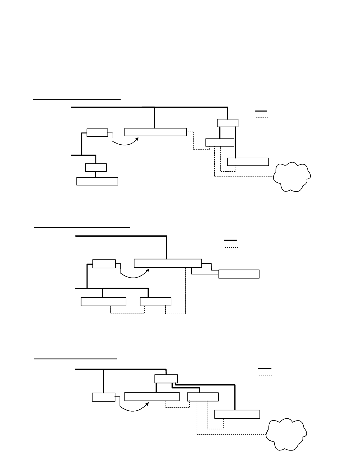
INSTALLATION NOTES
• It is not necessary to install an ENVIROMUX-ACVD-xxx to monitor the AC circuit which provides power to the ENVIROMUX-
SEMS-16. The ENVIROMUX-SEMS-16 has built-in power monitoring and battery backup and will send an alert in the event
of a power failure.
• In order for the ENVIROMUX-SEMS-16 to send an e-mail alert, the attached network components (routers, mail server, etc.)
must have power. If you are using the ENVIROMUX-SEMS-16 and ENVIROMUX-ACVD-xxx to monitor the AC circuit
providing power to any of these network components, be sure they will not lose power during a fault condition. (See image
below.)
ENVIROMUX-SEMS Installatio n #1
AC Circuit #1
AC Circuit #2
• If your network components will lose power during the AC fault condition, use an alternate means to send alerts such as a
GSM Modem (ENVIROMUX-GSM) or Auto Voice Dialer (ENVIROMUX-AVDS). The ENVIROMUX-GSM and ENVIROMUXAVDS are powered by the “Aux Pwr” port on the ENVIROMUX-SEMS-16. (See image below.)
ENVIROMUX-S EMS In sta ll atio n #2
AC Circuit #1
AC Circuit #2
• If you are using the ENVIROMUX-ACVD-xxx to monitor the AC Circuit which provides power to the ENVIROMUX-MINI or any
of the necessary network equipment (router, mail server, etc.), be sure they will not lose power during the AC fault condition.
(See image below.)
ENVIROMUX-MINI Installation
AC Circuit #1
ACVD
UPS
WEB SERVER
ACVD
MAIL SERVER
ENVIROMUX-SEMS-16
2-Wire Cable
ENVIROMUX-SEMS-16
2-Wire Cable
ROUTER
RS232
UPS
UPS
ROUTER
MAIL SERVER
Power cable
Ethernet cable
Aux. Pwr.
GSM Modem
Power cable
Ethernet cable
INTERNET
Power cable
Ethernet cable
ACVD ROUTER
ENVIROMUX-MINI
2-Wire Cable
MAIL SERVER
INTERNET
5
Page 6

TECHNICAL SPECIFICATIONS
DESCRIPTION SPECIFICATION
Input Voltage Range 0-250VAC
Power Powered by 35-250VAC via power cord (25mA Max.)
Size (In.) W x D x H 2x2.5x1
COPYRIGHT
Copyright © 2009 Network Technologies Inc All rights reserved. No part of this publication ma y be repr oduced, stored in a
retrieval system, or transmitted in any form or by any means, electronic, mechanical, photocopying, recording, or otherwise,
without the prior written consent of Network Technologies Inc, 1275 Danner Drive, Aurora, OH 44202.
CHANGES
The material in this guide is for information only and is subject to change without notice. Network Technologies Inc reserves the
right to make changes in the product design without reservation and without notification to its users.
WARRANTY INFORMATION
The warranty period on this product (parts and labor) is two (2) years from date of purchase. Please contact Network
Technologies Inc at (800) 742-8324 or 330-562-7070 for information regarding repa irs and/or returns. A return authorization
number is required for all repairs/returns.
MODEL NO: ENVIROMUX-ACVD-_____
SERIAL NO: ____________________
DATE: ______________________
INSPECTED BY: _____________________
MAN081 Revised 6/19/2009
6
 Loading...