

Page 1
ST-IPUSB4K-L/R-VW
4K2K HDMI with USB
Over Gigabit IP Ethernet
Setup Guide
1
Page 2
Panel and Connectors
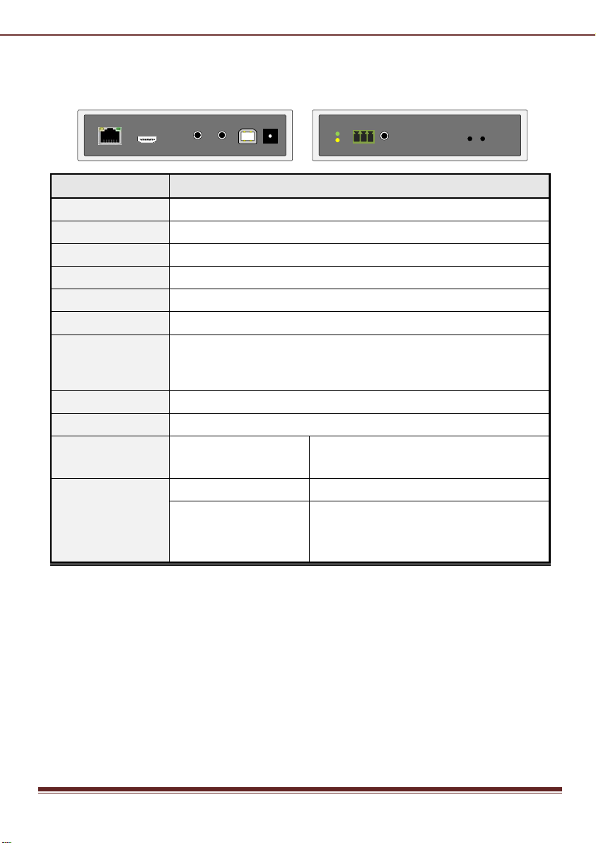
No. Connector
Description
1 Gigabit Ethernet
2 HDMI in
Connect to HDMI Source, or use HDMI-to-DVI adapter cable for DVI source.
3 Line in
4 Line out
5 USB-to-PC
Connect this USB-B to PC for USB 2.0 extension.
System power input.
7 System LED (Green)
Link LED (Amber)
Green Blinking/Amber Off: System is starting up.
Green On/Amber Off: System is ready, but TX/RX not connected.
Green On/Amber Blinking: TX/RX connected, but waiting for HDMI input.
Green On/Amber On: TX/RX connected, HDMI input is ready.
8 RS-232
Provide Serial-over-IP function. (Pin assignment: TxD-RxD-GND)
9 IR Blaster
Connect to external IR Transmitter
10 (Button 1)
Press and Hold at Power
ON until Green and Amber
LED blinking
1. Reset to the Factory default setting.
2. Enter Setup and Firmware upgrade mode in
192.168.0.88
11 (Button 2)
Short press
Set to Video/Graphic mode.
Long press (3 sec.)
To Enable/Disable Anti-Dither.
Note: For some of ATI graphic card with
Dithering function enabled, you may enable
Anti-Dither to achieve the better video quality.
7 9 108 11
1 2 3 4 5 6
Connect to Gigabit Ethernet switch or directly to Receiver.
Audio line in, it will be extended to the Line Out of the Receiver.
Audio line out, it is extended from Mic. In of the Receiver.
6 DC 24V In "PoE"
ST-IPUSB4K-L-VW Transmitter
2
Page 3
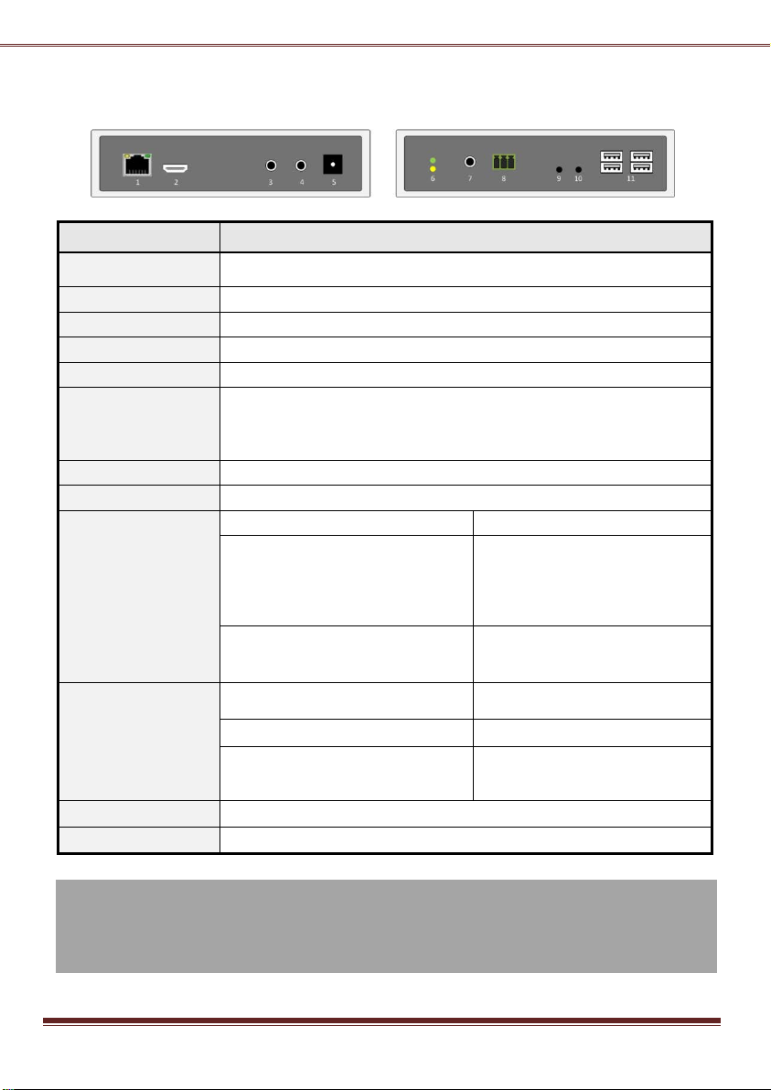
No. Connector
Description
1 Gigabit Ethernet
2 HDMI Out
This HDMI output connector supports HDMI 4K2k, 1080p output.
3 Mic. IN
4 Line OUT
5 DC 24V In "PoE"
System power input.
6 System LED (Green)
Link LED (Amber)
Green Blinking/Amber Off: System is starting up.
Green On/Amber Off: System is ready, but TX/RX not connected.
Green On/Amber Blinking: TX/RX connected, but waiting for HDMI input.
Green On/Amber On: TX/RX connected, HDMI input is ready.
7 IR Receiver
Remote Universal IR receiver (optional).
8 RS-232
Provide Serial-over-IP function. (Pin assignment: TxD-RxD-GND)
9 Mode button
Short press
Set to Video or Graphic mode.
Long press (3 sec.)
To Enable/Disable Anti-Dither.
Note: For some of ATI graphic card
with Dithering function enabled, you
may enable Anti-Dither to achieve
the better video quality.
Press and Hold at Power ON until
Green LED blinking
Get and Use this RX’s EDID as the
EDID)
10 Link button
Short press
To enable/disable Transmitter List
OSD
Long press (3 sec.)
To get the USB access right.
Press and Hold at Power ON until
Green and Amber LED blinking
1. Reset to the Factory default.
2. Enter Setup and Firmware
upgrade mode in 192.168.0.88
11 USB 1.1 Host
2 USB-A ports for USB 1.1 devices like Keyboard, Mouse, Printer, …
12 USB 2.0 Host
2 USB-A ports for USB 2.0 devices like USB Disk, Touch Screen, …
ST-IPUSB4K-R-VW Receiver
Connect to Gigabit Ethernet switch or directly to Transmitter.
Microphone Input, it will be extended to the Line Out of Transmitter.
Audio line out, it is extended from Line In of Transmitter.
system EDID (update Transmitter
3
Page 4
Configuration
The TX/RX unit built with Web page that supports Setup mode and Operation mode configuration.
Setup Mode Configuration
1. Press and Hold the unit’s [Button 1]/[Link] button and Power ON until Green and Amber LED blinking then
release the [Button 1]/[Link] button. This will
force TX/RX enter Setup mode.
2. Directly connect TX or RX to PC LAN port, set
PC IP to 192.168.0.1, Net Mask 255.255.255.0.
3. Open PC’s Web Browser and enter
192.168.0.88 <Enter>
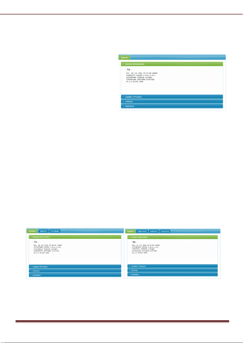
4. The Setup Mode Web page contains [System]
tab with sub-tabs of [Version Information],
[Update Firmware], [Utilities], and [Statistics]
as the screenshot on the right:
Reset to Factory default (Setup Mode)
If the device settings lost, you can reset the device back to the factory default:
1. Enter Setup Mode Web page [System] ---> [Utilities] ---> [Factory Default]
(The Factory default setting are shown on the label that under the unit)
Firmware Upgrade (Setup Mode)
1. Enter Setup Mode Web page [System] ---> [Update Firmware] ---> navigate to the firmware file (.bin) then
click [Upload] to start firmware upgrade.
2. The firmware upgrade takes about 3 min., it will display “DONE Rebooting…” to indicate the unit has been
upgraded and rebooted.
Operation Mode Configuration
The TX/RX can be configured in Operation Mode through Ethernet Switch or directly connected.
To enter Operation mode Web page:
1. Set PC IP 10.0.1.1, Net Mask 255.0.0.0.
2. Open Browser then enter TX/RX IP: 10.xx.xx.xx
3. The TX Operation Mode Web page is shown as the below left screenshot which contains 3 tab menus
[System], [Network], Functions]. The RX Operation Mode Web page is shown as the below right screenshot
which contains 4 tab menus [System], [Video Wall], [Network], Functions].
Firmware Upgrade (Operation Mode)
It is possible to do the firmware upgrade in Operation mode for TX/RX:
1. Enter Operation Mode Web page [System] ---> [Update Firmware] ---> navigate to the firmware file (.bin)
then click [Upload] to start firmware upgrade.
4
Page 5
2. The firmware upgrade takes about 3 min.,
it will display “DONE Rebooting…” to indicate
the unit has been upgraded and rebooted.
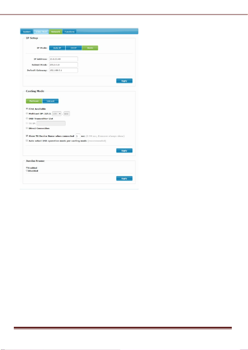
Network Configuration
The TX/RX provides the following Network
related settings:
To change IP
Enter TX/RX Operation Mode Web page
[Network] --->[IP Setup] --->select Auto IP,
DHCP, Static ---> enter device IP, Subnet Mask,
Default Gateway ---> [Apply].
To change Casting Mode
The TX/RX factory default is Multicast. To
change, enter TX/RX Operation Mode Web
page [Network] ---> [Casting Mode] --->
select [Multicast] or [Unicast] ---> [Apply].
Note: Each TX comes with one Individual IP
address and one Multicast IP address which
are shown on the unit label.
Connection Method (RX only)
There are 4 Connection Methods for
Multicast RX: First Available, Multicast IP,
OSD Transmitter List, and Direct Connection.
There are 4 Connection Methods for Unicast
RX: First available,OSD Transmitter List , TX IP
First Available: the RX will connect to the first available TX.
Multicast IP: 225.0.xxx.xxx: the RX will connect to the TX that is using the same Multicast IP
address.( (You can setup TX Multicast IP on the TX [Network] ---> [Casting Mode])
OSD Transmitter List: the RX will show up the available Transmitters for user to select.
TX IP: x.x.x.x: the RX will connect to this dedicated TX only.
Direct Connection: this setting enables RX to connect TX by the same subnet, same Casting Mode,
Jumbo Frame will be enabled.
and Direction Connection.
To show TX Device name when connected (RX only)
This feature enable RX to pop up the TX name (or IP) when connected. Default is enabled with 5 seconds.
To Enable/Disable Jumbo Frame
The TX/RX Jumbo Frame must be enabled for the 4K2K input and output (default Enabled). To enable or
disable it, enter TX/RX Operation mode Web page ---> [Network] ---> [Jumbo Frame] ---> Enable/Disable
---> [Apply] ---> the unit will save the setting and reboot automatically.
Note: both TX/RX and Ethernet Switch must be all Jumbo Frame enabled to work properly for 4K2K.
5
Page 6
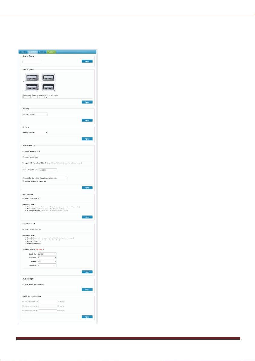
Functions Configuration
The TX/RX provides Operation mode Web page for Functions Configuration. The following screenshot shows
RX Web page as an example (TX is similar):
To change Device Name
Enter TX/RX Operation mode Web page ---> [Functions] ---> [Device
Name] ---> enter name (8 characters) ---> [Apply] to save the device
name.
To Enable/Disable KM over IP
The system supports both USB-over-IP and KM-over-IP for USB
extension. The USB-over-IP works as a Transparent 5-port USB Virtual
HUB when TX is connected to PC, it is compatible with most kind of
USB devices such as keyboard, mouse, Pen Drive, Touch Screen… etc.
The KM-over-IP is a HID emulation built for multiple RXs to share
keyboard/mouse for one PC, it takes one of 5 virtual ports. The
KM-over-IP setting is different for TX and RX:
For TX: enter TX Operation mode Web page ---> [Functions] ---> [USB
over IP] ---> [Compatibility Mode] ---> check/uncheck [K/M over IP]
to Enable/Disable(default enabled) --->[Apply].
For RX, enter RX Operation mode Web page ---> [Functions] --->
[KMoIP ports] ---> check/uncheck 1, 2, 3, 4 to Enable/Disable ports
for KM-over-IP (default all disabled) ---> [Apply].
To define Hotkey (RX only)
The RX supports Hotkey for OSD Menu. You can choose the Hotkey:
enter RX Operation mode Web page ---> [Functions] ---> [Hotkey]
---> select the Hotkey of <Ctrl><Ctrl>, <Shift> <Shift>, <Alt> <Alt>, or
<Scroll> <Scroll> (default Ctrl Ctrl).
To Enable/Disable Video over IP, Video Wall
Enter TX/RX Operation mode Web page ---> [Functions] ---> [Video
over IP] ---> check/uncheck [Enable Video over IP] and [Enable Video
Wall]
To Copy EDID from this Video Output (RX only)
You can assign a RX as the EDID Master: enter RX Operation mode
Web page ---> [Functions] ---> [Video over IP] ---> check/uncheck
[Copy EDID from this Video Output]
To change Scaler Output Mode (RX only)
The RX supports video-scale, to adjust it: enter RX Operation mode
Web page ---> [Functions] ---> [Video over IP] ---> [Scaler Output
Mode] ---> select the options of “Auto EDID”, “Pass
Through”, ”1080p60”, “1080p50”, “1920x1200”, “2160p30”,
“2160p25”, “Cutomize”(default Auto EDID)
To change Timeout for detecting video lost, to
enable Turn off screen on video lost (RX only)
Enter RX Operation mode Web page ---> [Functions] ---> [Video over
6
Page 7

IP] ---> [Timeout for detecting video lost] ---> select the Timeout value (default 10 sec.)
Enter RX Operation mode Web page ---> [Functions] ---> [Video over IP] ---> [Turn off screen on video lost]
---> check/uncheck to Enable/Disable (default Enable)
To change Maximum Bit Rate, Maximum Frame Rate (TX only)
Enter TX Operation mode Web page ---> [Functions] ---> [Video over IP] ---> [Maximum Bit Rate] ---> select
the options of “Best Effort”, “200 Mbps”, “150 Mbps”, “100 Mbps”, “50 Mbps”, “10 Mbps” (default Best
Effort).
Enter TX Operation mode Web page ---> [Functions] ---> [Video over IP] ---> [Maximum Frame Rate] --->
select % for the frames capture up (default 100%).
To Enable/Disable USB over IP
Enter TX/RX Operation mode Web page ---> [Functions] ---> [USB over IP] ---> [Enable USB over IP] --->
check/uncheck to Enable/Disable (default Enable).
Auto select mode: Auto selection “Active on link” if unit is in Unicast, select “Active per request” if unit is in
Multicast.
Active on link: USB over IP will be established in sharing mode when TX/RX connection established.
Active per request: USB over IP can be manually requested in exclusive mode, the former RX of the USB
over IP connection will be stopped if the current request is succeeded.
KM over IP Compatibility Mode setting (TX only)
Enter TX Operation mode Web page ---> [Functions] ---> [USB over IP] ---> [Compatibility Mode] --->
check/uncheck to Enable/Disable options of Mouse not responding well, and K/M over IP (default Enable).
To Enable/Disable Serial over IP, and select Operation Mode
Enter TX/RX Operation mode Web page ---> [Functions] ---> [Serial over IP] ---> check/uncheck to
Enable/Disable (default Enable).
Enter TX/RX Operation mode Web page ---> [Functions] ---> [Serial over IP] ---> [Operation Mode] --->
select options of Type 1, Type 2, Type 1 guest mode, Type 2 guest mode (default Type 2).
Note: Type 1 is mainly for Unicast application which user can dynamically link with any target RX.
Type 2 is mainly for Multicast application which TX will RS-232 link with all of connected RXs (default).
Type 1 guest mode is similar to type 1 but using PC to link with RX’s RS-232.
Type 2 guest mode is similar to type 2 but using PC to link with RX’s RS-232.
For details, please refer to “How to Use RS232 over IP” manual.
To define RS-232 parameters for Type 2
Enter TX/RX Operation mode Web page ---> [Functions] ---> [Serial over IP] ---> [Baudrate Setting for Type
2] ---> select Baudrate, Data bits, Parity, Stop bits. (default 115200, 8-n-1)
Audio Output (RX only)
If the input audio on TX is HDMI, you can set the Audio output on Line Out:
Enter RX Operation mode Web page ---> [Functions] ---> [Audio Output] ---> check “HDMI Audio
De-Embedder for the audio output to Line-Out. Click [Apply] to save the setting and reboot.
Multi-Screen Setting
The system supports Multi-Screen feature which is useful for PC with multiple screens. Each TX/RX can
define its associated 2nd, 3rd, 4th TX/RX IP. So, when the Main RX switches to a new TX, its associated RXs will
also be switched to that new TX’s associated TXs automatically.
Enter TX/RX Operation mode Web page ---> [Functions] ---> [Multi-Screen Setting] ---> then enter IP
address for the associated 2nd, 3rd, 4th TX/RX IP.
7
Page 8
There is a RX option of “Mirror”, when it is enabled, the associated RXs will connect to the same TX as the
Main RX is connecting. This enables multiple RXs to display the same TX as a splitter.
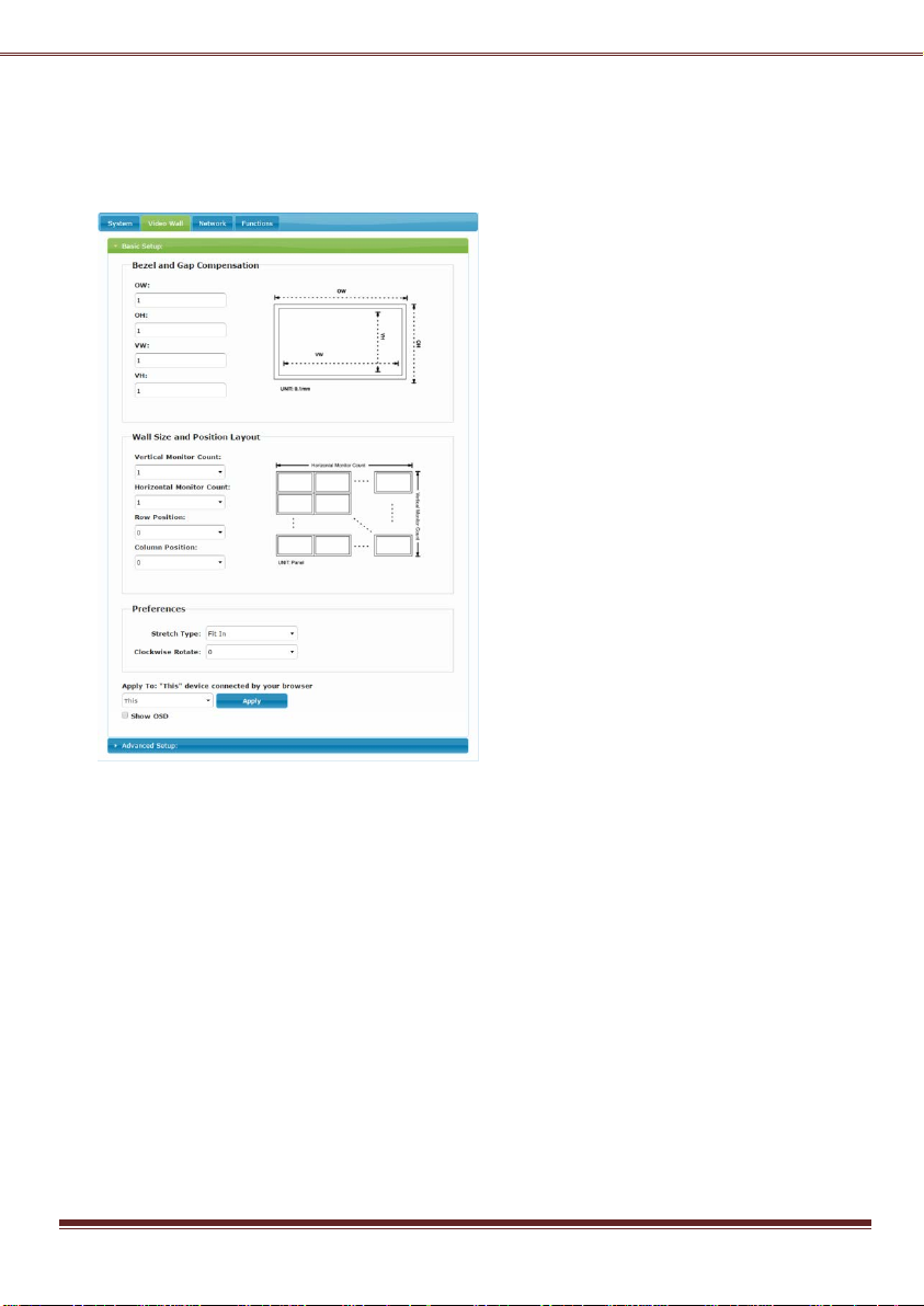
Video Wall Configuration (RX only)
The RX provides the following Video Wall related settings:
To adjust Bezel and Gap
Compensation
Enter RX Operation mode Web page ---> [Video
Wall] ---> [Basic Setup] ---> Measure and enter the
value for OW (Outside Width), OH (Outside Height),
VW (View Width), VH (View Height) in 0.1mm unit
---> [Apply].
To define Wall Size and Position
Layout
Enter RX Operation mode Web page ---> [Video
Wall] ---> [Basic Setup] ---> select the value for
Vertical Monitor Count, Horizontal Monitor Count,
Row Position, Column Position from the drop-down
menu ---> [Apply].
To define Stretch and Rotation
Enter RX Operation mode Web page ---> [Video
Wall] ---> [Basic Setup] ---> [Preferences] --->
[Stretch Type] ---> select options of ”Fit In” and
“Stretch Out” ---> [Apply]
[Clockwise Rotate] ---> select 0, 180, 270 rotation
--> [Apply]
Note:
Fit In: Stretch the full screen to the whole wall.
Stretch Out: keep picture aspect ratio and stretch out of the screen if needed.
To Show OSD
To identify the screen, check the “Show OSD” and select the device then click [Apply] button.
Video Wall Advanced Setup (RX only)
The Advanced Setup can be used for special effects which are not included in Basic Setup. There are two
steps in advanced setup:
Step 1: Choose one or more target(s) to apply setup to.
Step 2: After the targets are selected, changes can be applied in Step 2.
8
Page 9
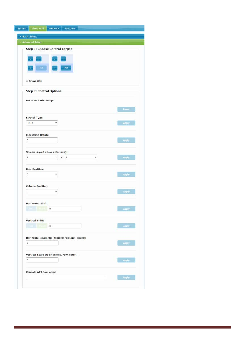
Reset to Basic Setup:
Reset the target(s) to the setting of “Basic
Setup”.
Stretch Type:
Fit In: Stretch the full screen to the whole
wall.
Stretch Out: keep picture aspect ratio
and stretch out of the screen if needed.
Clockwise Rotate:
0: No rotate
180: clockwise rotate 180 degree
270: clockwise rotate 270 degree
Screen Layout (Row x
Column):
To define the Video Wall size, select the
Row and Column count from the
drop-down menu.
Row Position:
To set the Row position for the selected
target RX. (The Row starting from 0)
Column Position:
To set the Column position for the
selected target RX. (The Column starting
from 0)
Horizontal Shift (Left,
Right):
Horizontal shift target screen to left or
right in 1 pixel unit.
Vertical Shift (Left, Right):
Vertical shift target screen to left or right
in 1 pixel unit.
Horizontal Scale Up
Horizontal scale up the target screen in
(1/column count) pixel.
Vertical Scale Up
Vertical scale up the target screen in
(1/row count) pixel.
9
Page 10

Installation
1. The system factory default Connection Method for RX is “First Available”, and TX is in Multicast mode with
its default Multicast IP which shown on the label. This means all of TXs will send packets with its default
Multicast IP (225.0.xxx.xxx), and all of RXs will find the first available TX for connection. Please refer to page
5 for how to change Connection Method.
2. Use a CAT6 UTP cable (straight, EIA 568B) to directly connect TX/RX as a pair connection, or connects to
IGMP enabled Gigabit Ethernet switch for the many TXs-to-many RXs installation.
Note: Each TX comes with individual factory default Multicast IP which shown on the unit label.
3. Connects RX HDMI-Out to screen by HDMI cable.
4. Assign a specific RX as the EDID Master. To do this, press and hold the [Mode] button of the specific RX unit
and power ON until Green LED blinking then release the [Mode] button. Then power ON other RX units
sequentially. In this step, RX’s Green LED will blink then ON, and Amber LED Off to indicate it is ready and
waiting for connecting with TX. (or refer to page 6 “To Copy EDID from this Video Output” to assign a
specific RX as EDID Master)
5. The following start-up messages will be displayed during RX powered on:
FW: 16-Jul-18 A6.2.5 ---> Firmware version
Local IP: 10.0.34.38 ---> RX’s IP address
MAC: 0020FExxxxxx ---> RX’s MAC address
Connection Method:
---> Possible messages are: “First Available”,
Multicast or TX IP, “OSD Transmitter List”,
“Direct Connection”.
Remote IP: 10.0.x.x / 225.0.x.x
---> Connecting target TX IP / Multicast IP.
6. If the HDMI input source is 4K2K then please refer to page 5 to enable TX/RX Jumbo Frame setting, and
set Ethernet Switch Jumbo Frame with minimum 8K bytes to get the best video quality.
7. Attach HDMI/DVI source to the TX’s HDMI-In. Then power ON the TX unit. The TX’s Green LED will blink
then ON to indicate ready and wait for connection with RX.
8. As long as TX/RX connection established, both of TX and RX Amber LED will start to blink indicating wait for
video input source (Green LED is ON).
9. If you are using PC as video source, it is recommended to check if the correct screen EDID shown on PC
graphic card control panel.
10. Activate video with audio source to TX, then check if all RXs are correctly displayed. In this step, both Green
and Amber LED should be ON to indicate the unit is ready and video source is also ready.
USB and KM over IP installation
11. Connects TX USB-B to PC, OS will detect a Generic USB Virtual Hub Device.
12. The system can support both “USB-over-IP” and “KM-over-IP”.
The USB-over-IP works as a Virtual 5-port HUB when connected to TX, it is compatible with most kind of
USB devices such as keyboard, mouse, Pen Drive, Touch Screen… The USB-over-IP connection can be
configured in “Active on link” (Sharing) mode or in “Active per request” (Exclusive) mode (default). In
“Active on link” mode, the maximum USB-over-IP connection for a TX is 5 due to the 5 ports of Virtual HUB.
10
Page 11
The KM-over-IP means that USB port will work as HID device only for keyboard/mouse emulation, the PC
don’t get BIOS “Keyboard Error” if there is no real keyboard attached during boot up. It is not necessary to
gain USB access right for the KM-over-IP port. The TX (PC) can be shared with multiple RXs for
keyboard/mouse access in KM-over-IP mode.
13. There are 4 USB-A ports on the RX. The factory default setting for the TX is both of USB-over-IP and
KM-over-IP enabled, all 4 USB ports of RX are in USB-over-IP mode (KM-over-IP disabled).
14. There are 2 methods to gain the access right for a USB-over-IP port:
14.1 Long press (3 sec.) the RX [Link button].
14.2 Press “U” key to toggle during Transmitter List OSD menu.
The RX display “Requesting USB” to indicate starting USB-over-IP connection, and message of “Starting USB”
will be displayed if it successfully gained the USB access right. Meanwhile, the previous USB Master unit will
show an OSD message of “USB Stopping”.
RX OSD Main Menu
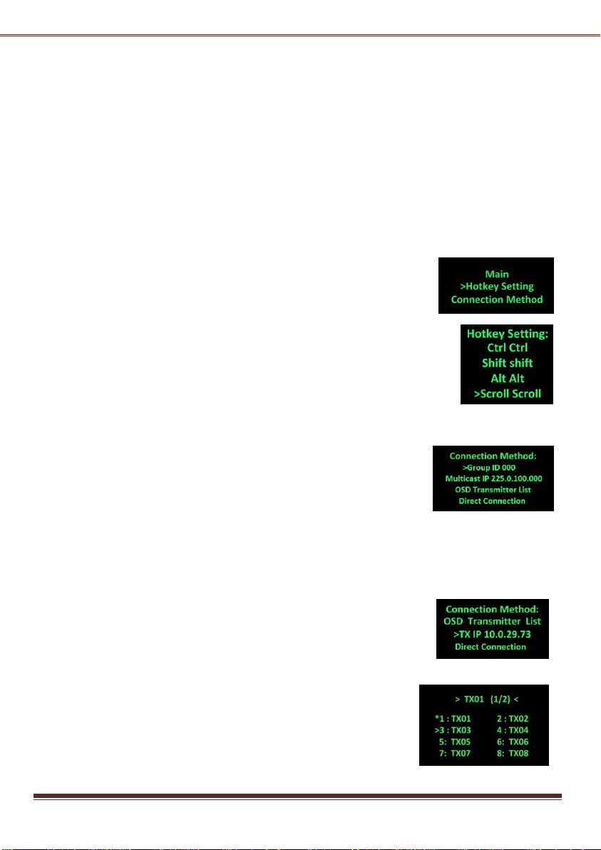
The RX supports OSD menu, press the RX’s [Link] button to get the OSD Main
menu: [Hotkey Setting] and [Connection Method].
RX OSD Hotkey selection Sub-Menu
From the OSD Main Menu, press [Link] button to move the highlight arrow to
[Hotkey Setting]. Wait a few seconds, the sub-menu will show up with 4 possible
selections: “Ctrl Ctrl”, “Shift Shift”, “Alt Alt”, or “Scroll Scroll”. Press [Link] button
again to move the highlight arrow to the desired selection. The RX unit will be
re-booted.
RX OSD Connection Method Sub-Menu
From the OSD Main Menu, press [Link] button to move the highlight arrow to
[Connection Method]. Wait a few seconds, either Multicast or Unicast
Connection Method sub-menu will show up depending on the RX’s Casting
mode.
The Multicast RX supports 4 possible connection methods: First Available,
Multicast IP, Transmitter List, and Direct Connection, as the right picture:
The First Available means the RX will connect to the first available TX that it finds on the network.
The Multicast IP 225.0.100.000 means the RX will connect to the TX with the same Multicast IP.
The OSD Transmitter List means the RX will show up the available Transmitters for user to select when
<Hotkey> <Hotkey> is pressed.
The Direct Connection means the RX will connect to a specific TX as a pair connection.
The Unicast RX supports 3 possible connection methods: OSD Transmitter List,
Dedicated TX IP, and Direct Connection, as the right picture:
Press the [Link] button to move the highlight arrow to the desired selection
and wait a while to confirm the selection.
Please note the Sub-Menu only provide selection, the Multicast IP or TX
IP can only be changed by the Web page setting.
RX OSD Transmitter List
Attach a keyboard to the RX’s any USB port, press <hotkey> <hotkey>. The
OSD List with maximum 8 Transmitters will be shown, as the right-hand
11
Page 12
picture indicates, the top line “TX01 (1/2)” means the current connection is “TX01” and there are 2 pages
and currently it’s on page 1. The TX with an asterisk (*) mark indicates the current connected TX.
You can select TX by the↑↓←→key and <Enter>, or 1 ~ 8 key to immediately connect to that TX.
Press F5 to refresh Transmitter List. Press U to request (or release) USB-over-IP. To end of OSD, press <ESC>
Connection Manager and Video-Wall Manager
The system provides Windows based Connection Manager and Video-Wall Manager software for the TX/RX
connection and Video-Wall management. Please refer to the Connection Manager and Video Wall Manager
Guide for details.
12
 Loading...