

Page 1
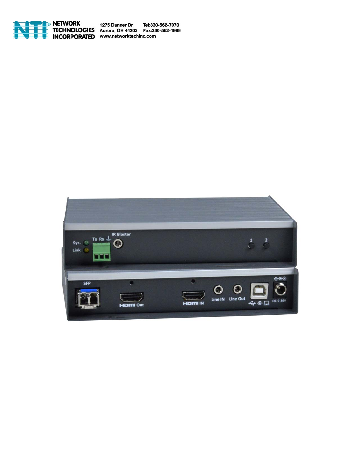
ST-IPFOUSB4K-L/R-LCVW
4K HDMI USB KVM Extender with Video Wall Support
Over IP via Two LC Singlemode/Multimode
Fiber Optic Cables
MAN374 REV 6/5/20
Page 2

INTRODUCTION ................................................................................................................................................................1
FEATURES AND FUNCTIONS..........................................................................................................................................2
CONFIGURATION..............................................................................................................................................................4
Setup Mode Configuration................................................................................................................................................................. 4
Operation Mode Configuration ..........................................................................................................................................................5
System........................................................................................................................................................................................... 5
Network .........................................................................................................................................................................................9
Functions.....................................................................................................................................................................................11
Video Wall Functions...................................................................................................................................................................19
INSTALLATION(TX/RX) ..................................................................................................................................................23
USB over IP and KM over IP installation.........................................................................................................................................23
Panel Button and Hotkey Operation................................................................................................................................................26
SPECIFICATIONS............................................................................................................................................................28
WARRANTY INFORMATION ..........................................................................................................................................29
Page 3

INTRODUCTION
The XTENDEX® 4K(30Hz) HDMI USB KVM Extender over IP via Fiber provides remote KVM (USB keyboard, USB mouse
(USB1.x/USB2) and 4Kx2K UHD HDMI monitor) access to a USB computer up to 9,842 feet (3,000 meters) away via a duplex LC
singlemode fiber optic cable and 1,804 feet (550 meters) using duplex LC multimode fiber optic cable.
Each KVM extender consists of a local unit that connects to a computer and also supplies video to a local monitor, and a remote
unit that connects to an HDMI monitor, 3.5mm stereo audio speakers and microphone, RS232, and up to four USB devices
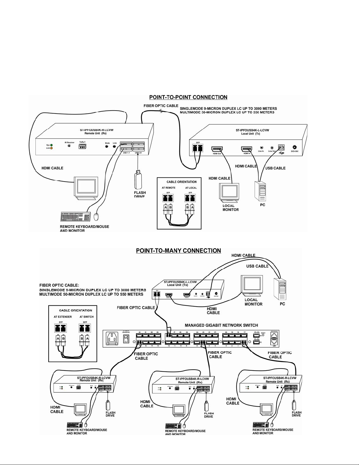
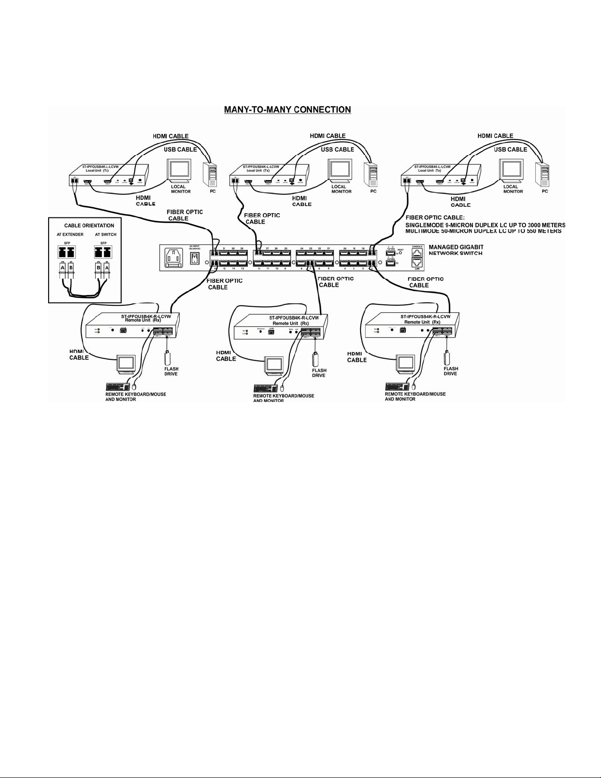
(keyboard, mouse, flash drive, HDD, or touchscreen display). The local and remote units can be connected together for a Point-toPoint connection via fiber cable, or a Point-to-Many or Many-to-Many connection via a managed Gigabit network switch.
Features:
Signal transmission via two-strand singlemode LC fiber optic cable.
o Using singlemode 9-micron cable, extend to 9,842 feet (3,000 meters).
o Using multimode 50-micron cable, extend to 1,804 feet (550 meters).
Supports Ultra-HD 4Kx2K resolutions to 3840x2160 (30Hz), 2K resolution 2048x1080, HDTV resolutions to 1080p, and up
to 1920x1200 (WUXGA).
HDMI features supported:
o HDMI 1.4
o x.v.Color, sYCC601 color, Adobe RGB Color and Adobe YCC601 color
o Dolby TrueHD, LPCM 7.1, DTS-HD Master Audio, Dolby Digital, and DTS
o Bandwidth up to 340 MHz (10.2 Gbps)
o Lip Sync
o HDCP 1.4 compliant.
USB ports for keyboard, mouse, flash drive, HDD or touchscreen display.
o Keyboard and mouse are hot-pluggable.
Supports video wall installations from 1x2 to 8x16 screens.
o Displays can be rotated 180 and 270°.
Plug-and-Play installation allows receivers to find the transmitter automatically on the same network. (Network
configuration may be required for managed network switch.)
Support for Point-to-Many or Many-to-Many connections requires a managed Gigabit network switch with IGMP support
and Jumbo frame support.
o Manage transmitter/receiver connections and video wall configuration with web interface or network switch that
supports VLAN; Each VLAN group acts as a separate HDMI Over IP Channel on the network.
When using multiple remote units, there are two USB control modes - Exclusive Mode and Sharing Mo de.
o USB Exclusive Mode: Only one remote unit can have USB control over the source computer at any time.
o USB Sharing Mode: Multiple remote units share the control of the source computer.
Up to 5 USB devices will be recognized by the computer.
Full Infrared Remote (IR) control of HDMI source from remote HDTV using existing source remote control.
Supports full-duplex RS232 up to 115200 baud.
Customizable EDID table on local unit.
Supp
Easily expandable – add receivers as you add control stations.
Integrated mounting brackets for easy surface/wall mounting.
orts the DDC2B protocol.
1
Page 4
FEATURES AND FUNCTIONS
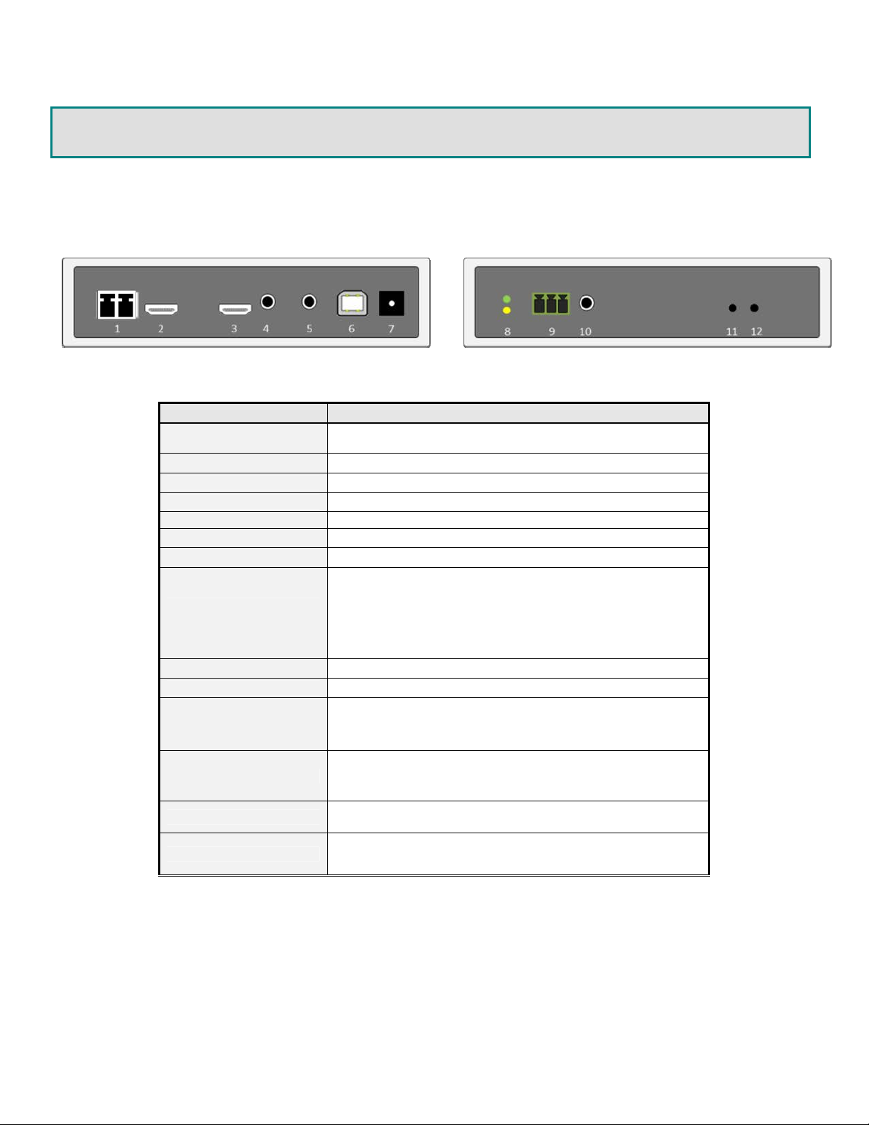
ST‐IPFOUSB4K‐L‐LCVWLocalUnit(TX)
No. Connector Description
1 SFP Port
2 HDMI OUT Local HDMI loop-out
3 HDMI IN Supports HDMI input video source up to 4K30Hz
4 Line in 3.5mm input audio will be extended to the Line Out of RX
5 Line out 3.5mm Line Out audio is extended from Microphone of RX
6 USB-to-PC USB-B to PC USB port for USB 2.0 Virtual HUB extension
7 DC 9~32V In System power input.
8 System LED (Green)
Link LED (Amber)
9 RS-232 (terminal block) Serial-over-IP function, pin assignment: TxD-RxD-GND
10 IR Blaster Connect to external IR Emitter
11 Button 1
Connect to Ethernet Switch SFP port or directly to RX using
duplex LC fiber optic cable with pre-installed transceiver
Green Blinking/Amber Off: System is starting up.
Green On/Amber Off: System is ready, but TX/RX not
connected.
Green On/Amber Blinking: TX/RX connected, but waiting for
video input.
Green On/Amber On:TX/RX connected, video input is ready.
Press and Hold at Power ON until Green and Amber LEDs are
blinking:
Reset to Factory default and enter 192.168.0.88 setup mode.
12 Button 2
Press and hold for 3 sec.: To Lock RX’s keyboard and mouse.
Press: To select Video/Graphic mode
Press and hold for 3 sec.: To Enable/Disable Anti-Dither.
2
Page 5
y
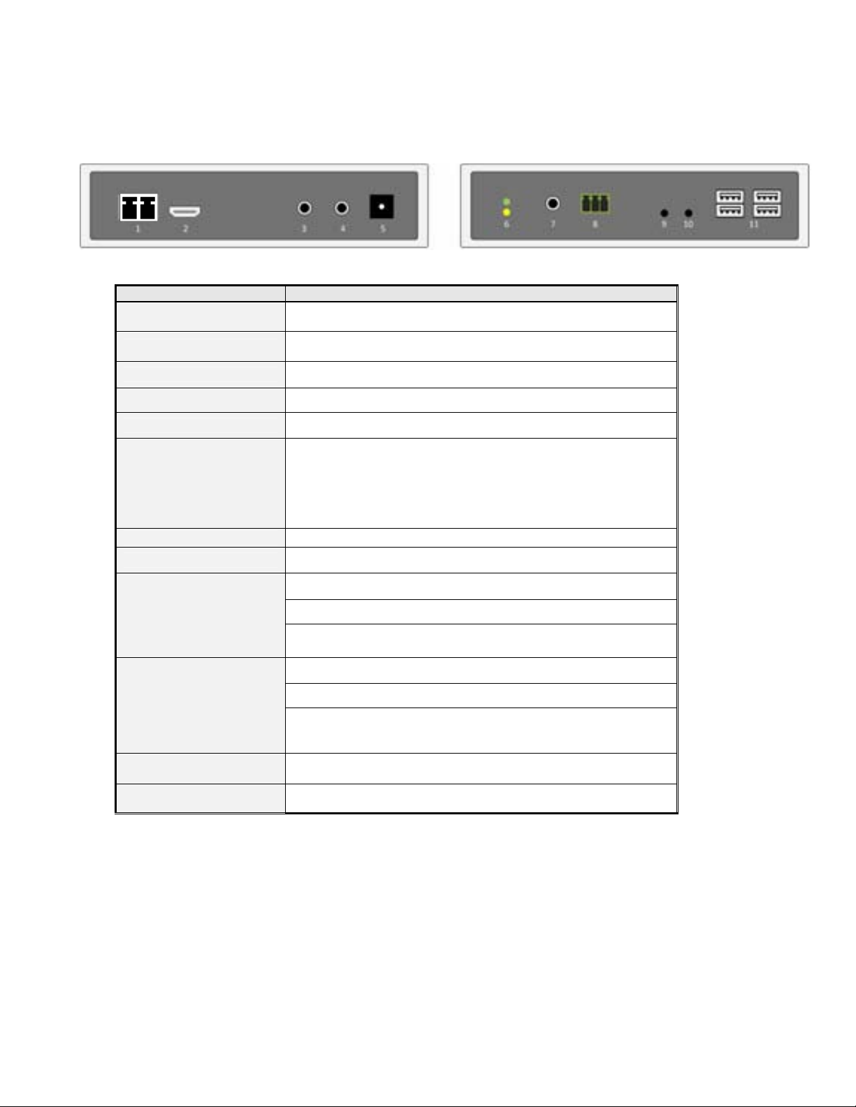
ST‐IPFOUSB4K‐R‐LCVWRemoteUnit(RX)
No. Connector Description
1 SFP Port
2 HDMI Out Connect to HDMI screen by HDMI-to-HDMI cable
Connect to Ethernet switch SFP port or directly to TX using duplex
LC fiber optic cable with pre-installed transceiver
3 Mic. IN
4 Line OUT 3.5mm Line Out, can be Line In or HDMI audio of source TX
5 DC 9~32V In System power input.
6 System LED(Green)
Link LED (Amber)
7 IR Receiver Remote Universal IR receiver(optional)
8 RS-232 (terminal block) Serial-over-IP function. (Pin assignment: TxD-RxD-GND)
9 Mode button
10 Link button
11 USB 1.1 Host 2 x USB 1.1 ports (left) for Keyboard, Mouse
3.5mm Mic. In, extended to Line Out of TX (Unicast mode)
Green Blinking/Amber Off: System is starting up.
Green On/Amber Off: System is ready, but TX/RX is not
connected.
Green On/Amber Blinking: TX/RX connected, waiting for video
source.
Green On/Amber On: TX/RX connected, input video source is read
Press: To select Video/Graphic mode
Press and hold for 3 sec.: To Enable/Disable Anti-Dither
Press and Hold at Power ON until Green LED is blinking:
Set this RX as EDID Master
Press: To enter OSD Transmitter List menu
Press and hold for 3 sec.: To request USB access right.
Press and Hold at Power ON until Green and Amber LEDs are
blinking:
Reset to Factory default and enter 192.168.0.88 Setup mode
11 USB 2.0 Host
2 x USB 2.0 ports (right) for Disk, Touchscreen, etc …
3
Page 6
CONFIGURATION
Use TX/RX Configuration Web page to configure. There are Setup mode and Oper at ion mode for the Configuration Web page.
Setup mode can be used in the event you change the IP address of the unit in Operation mode and forget what it is. The Setup
Mode IP address cannot be changed. By entering Setup mode, the Version Information screen will tell you what the current
Operation Mode IP address is.
Setup Mode Configuration
To enter TX/RX Setup Mode Configuration Web page, press and hold the Button 1 (on Tx) or Link button (on Rx) and Power ON
until the Green and Amber LEDs start blinking, then release the button. This will force the TX/RX to enter Setup mode.
1. Directly connect TX/RX to a PC LAN port and set the PC IP to 192.168.0.1, Net Mask 255.255.255.0.
2. Open PC’s Web Browser (we recommend Chrome) and enter IP address 192.168.0.88 to enter the Setup Mode Configuration
Web page.
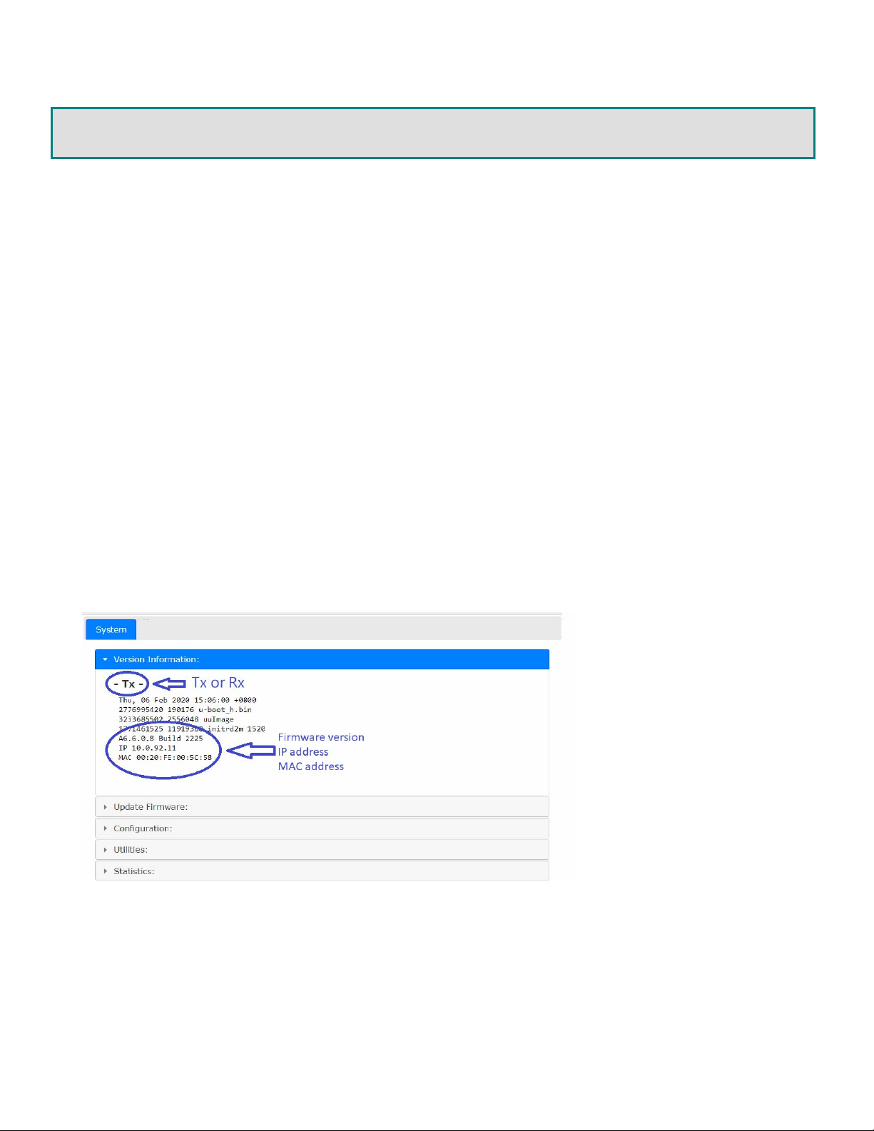
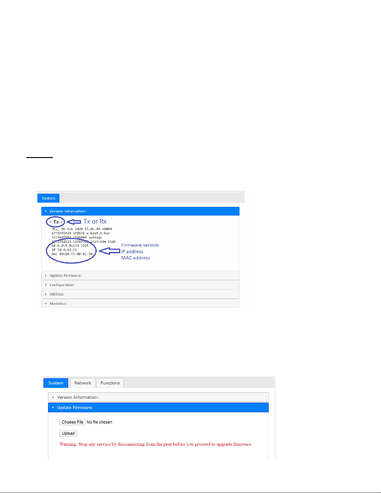
The Setup Mode Configuration Web page contains a System tab with sub-tabs Version Information, Update Firmware,
Configuration, Utilities, and Statistics. For determining the IP address, you only need the System tab and Version Information
(below).
Version Information
Provides information for “Tx” or “Rx”, Firmware version, IP address, MAC address:
4
Page 7
Operation Mode Configuration
To enter TX/RX Operation mode Configuration Web page:
Set PC IP 10.0.1.1, Net Mask 255.0.0.0.
Open Browser (we recommend Chrome), then enter TX/RX IP address 10.xx.xx.xx (the IP address can be found on the bottom of
the unit).
The TX Configuration Web Page contains 3 subtabs: System , Network , Functions .
The RX Configuration Web Page contains 4 subtabs: System , Video Wall , Network , Functions .
System
Version Information
Provides information for “Tx” or “Rx”, Firmware version, IP address, MAC address:
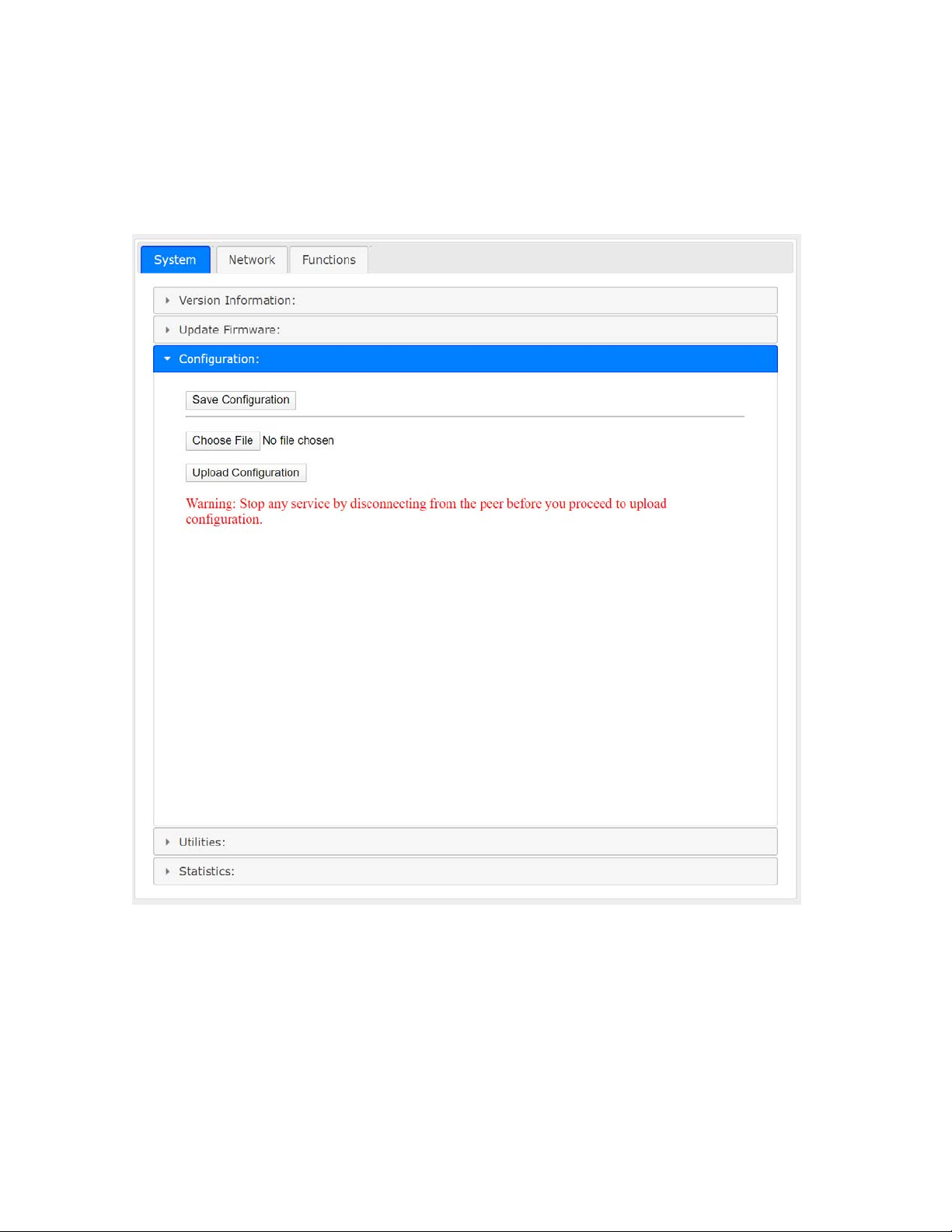
Update Firmware
Enter Update Firmware ---> navigate to the firmware file (.bin) then click Upload to start a firmware upgrade. The firmware
upgrade takes about 3 minutes, after which it will display “DONE Rebooting…” to indicate the unit has been upgraded and
rebooted.
5
Page 8
Configuration
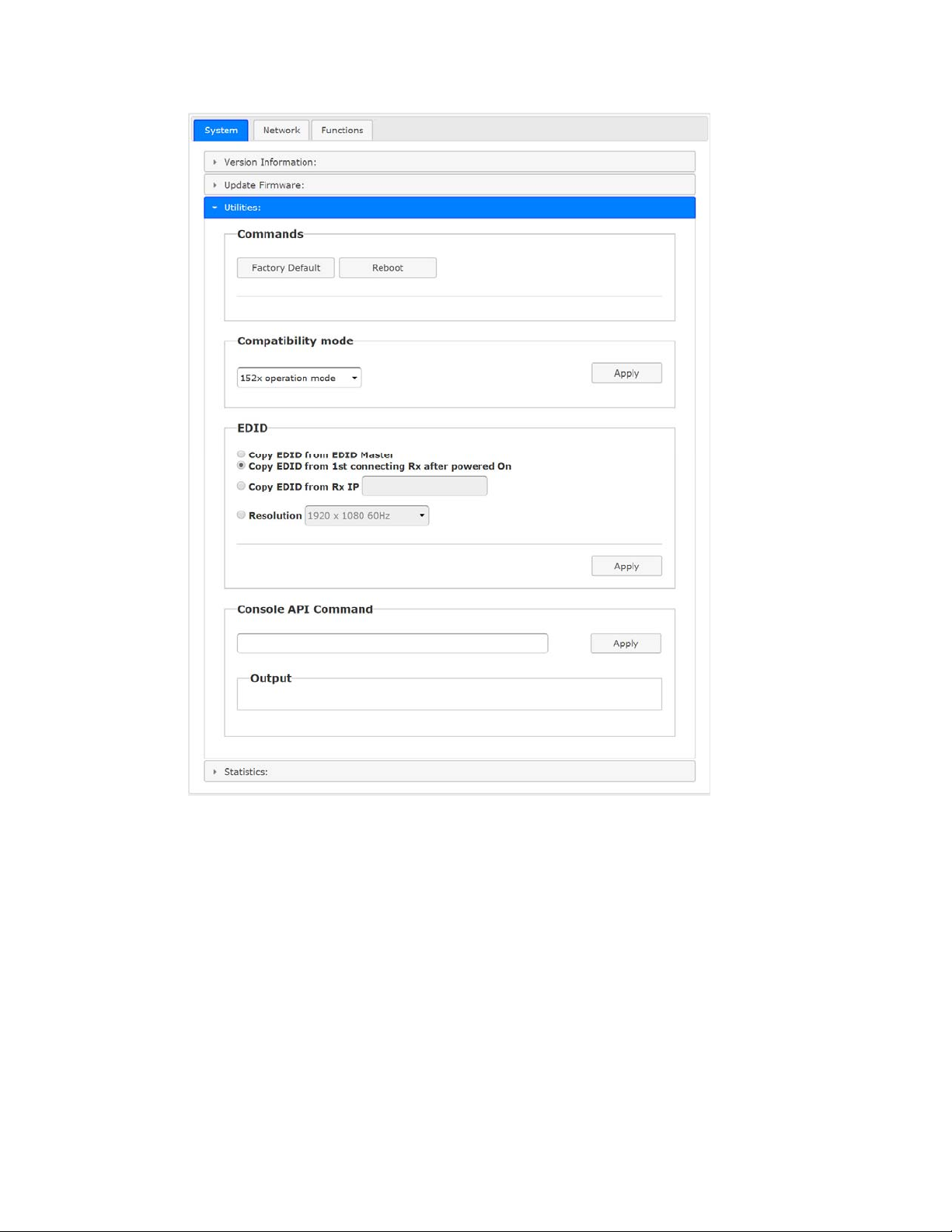
You can export the current settings to a configuration file, or import configuration from an external file. Enter Configuration --->
Click Save Configuration to export configuration, click Upload Configuration to import configuration.
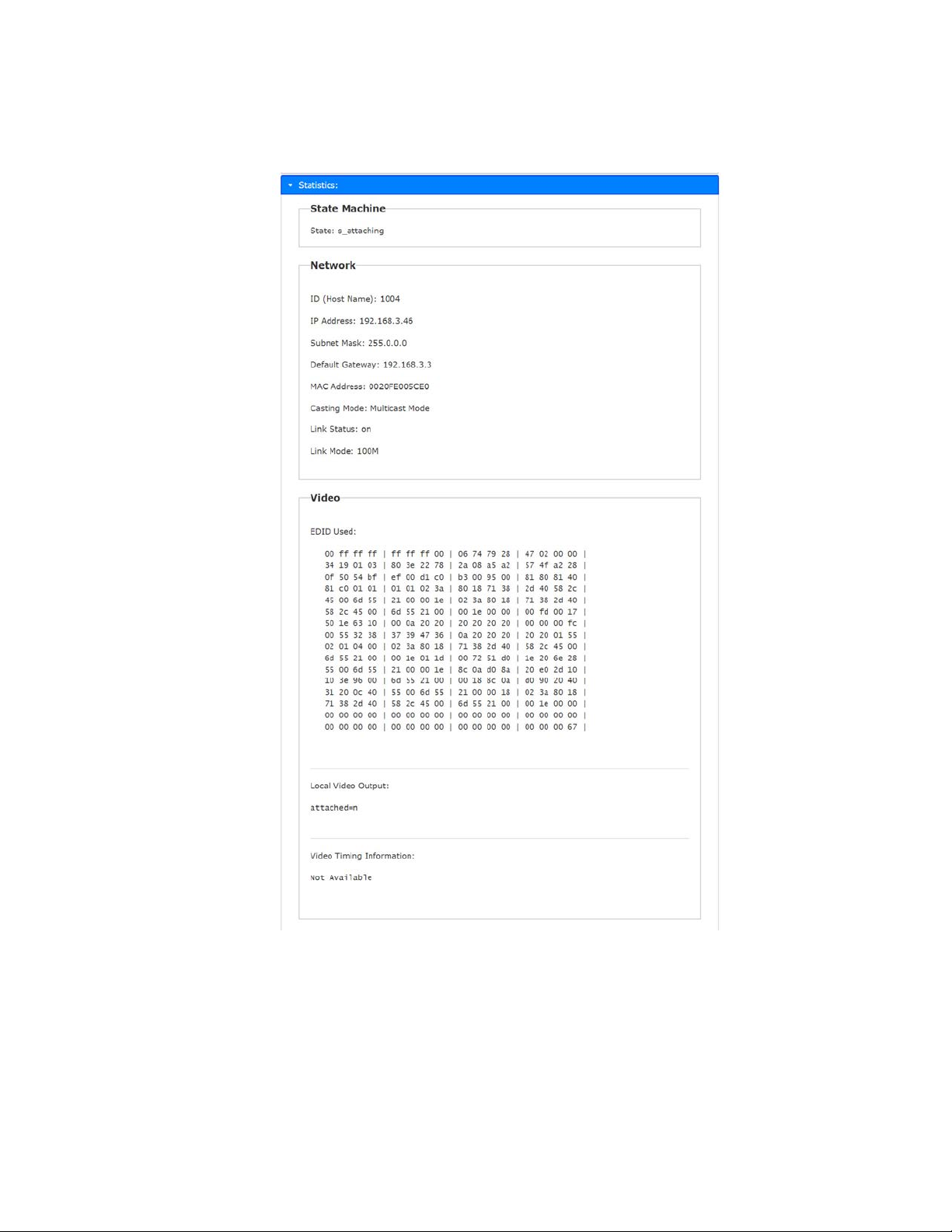
Utilities
Commands ---> Factory Default ---> To reset the device to the factory default.
Command ---> Reboot ---> To reboot the device.
Compatibility mode ---> Not applicable to this product
6
Page 9
EDID (TX only, not in RX)
The TX provides flexible EDID selections:
Copy EDID from EDID Master --->TX will get EDID from the RX with EDID Master setting.
Copy EDID from 1
Copy EDID from RX IP--->TX will get EDID from a specific RX, enter RX’s IP here.
Resolution--->You can set TX with a specific resolution from the drop-down menu.
Available resolutions are 3840x2160 30Hz, 2560x1440 60Hz, 1920 x 1200 60Hz, 1920 x 1080 60Hz(default), 1680 x
1050 60Hz, 1440 x 900 60Hz, 1366 x 768 60Hz, 1280 x 1024 60Hz, 1280 x 720 60Hz, 1024 x 768 60Hz, 720 x 480 60Hz.
Note: This Resolution option will be overwritten by the RX EDID Master if the TX is set on Unicast.
Console API Command --->Not applicable to this product
st
connecting RX after powered On--->TX will get EDID from the 1st connected RX.
7
Page 10
Statistics
Display system status for State Machine, Network, Video EDID, Video Screen attachment, Video Timing.
8
Page 11
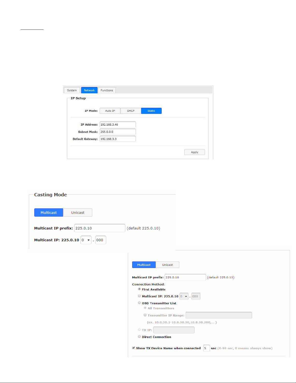
Network
IP Setup (TX/RX)
The system supports Auto IP, DHCP, and Static(default) for the IP configuration:
Auto IP ---> 169.254.xxx.xxx (Auto), Subnet Mask 255.2555.0.0, Default Gateway 192.168.0.1
DHCP ---> Get IP from DHCP Server
Static ---> Enter IP Address, Subnet Mask, Default Gateway, click Apply .
Casting Mode (TX)
TX can be set in Multicast (default) or Unicast mode.
In Multicast mode, the Multicast IP prefix can be configured:
Multicast IP prefix (default 225.0.10)
Multicast IP address (prefixed with
225.0.10x.x)
Casting Mode (RX)
The RX can be set in Multicast (default)
or Unicast mode as the below.
In Multicast mode, you can setup the
Multicast IP prefix and select the
Connection Method from:
First Available (default),
Multicast IP,
OSD Transmitter List, and
Direct Connection.
9
Page 12
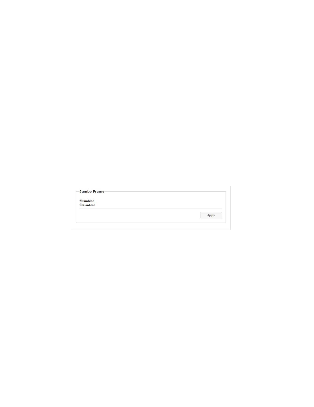
In Unicast mode, you can select the Connection Method from
First Available,
OSD Transmitter List,
TX IP and
Direct Connection.
RX supports the following Connection Methods:
First Available: the RX will connect to the first available TX when powered on.
Multicast IP 225.0.10x.xxx: the RX will connect to the TX with the same Multicast IP address specified here.
OSD Transmitter List: the RX will display the available TXs in the OSD menu for user to select. Select “All
Transmitters” if all of TXs are permitted. Select “Transmitter IP Range” and input the IP range with “-“ and“,”.
For example, “10.0.92.101 – 10.0.92.120, 10.0.92.135, 10.0.92.188, …”
TX IP: the RX will connect to this specified TX only.
Direct Connection: this setting enables RX to connect TX by the same subnet, same Casting Mode, Jumbo
Frame and EDID Master will be automatically enabled.
Show TX Device name when connected (RX)
This feature enables RX to display the TX name (or IP) when connected. Default is enabled with 5 seconds.
Jumbo Frame (TX/RX)
The TX/RX supports Jumbo Frame (8K bytes) for better video quality, default Enabled.
Note: The Ethernet Switch also must be set with Jumbo Frame enabled (at least 8K) if TX has been enabled.
10
Page 13
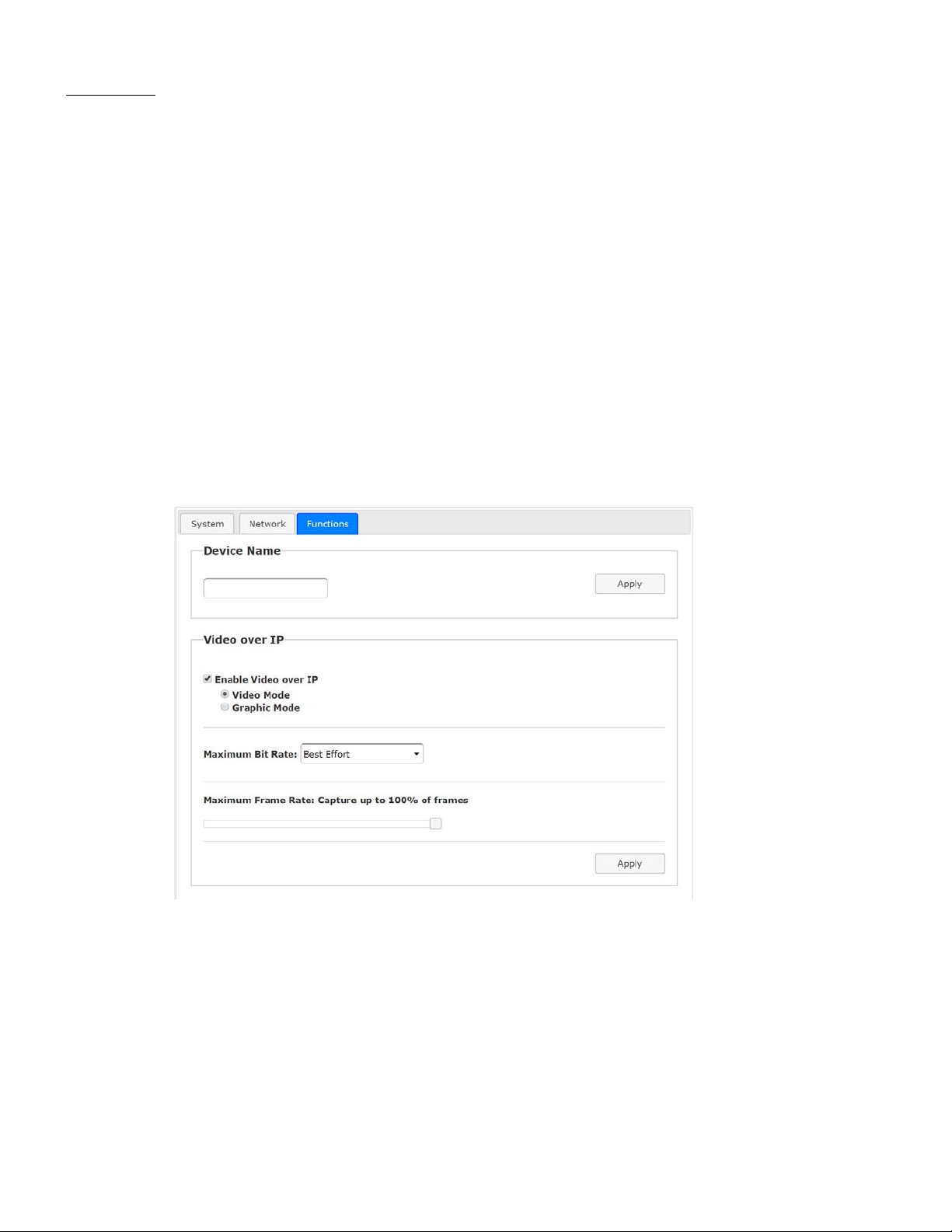
Functions
Device Name (TX/RX)
To set TX/RX Device name, enter ---> Functions ---> Device Name --->input name (8 characters max) --->
Apply to save the Device Name.
Video over IP (TX)
Features Include:
Enable Video over IP (Default: Enabled)
Video/Graphic Mode :Select Video Mode for video play smoothly.
Select Graphic Mode for static picture KVM application.
Maximum Bit Rate :Options are “Best Effort”, “200, 150, 100, 50, and 10 Mbps” for the TX bandwidth
selection.
(Default: Best Effort).
Maximum Frame Rate :This provides the maximum % of the TX frames rate capture up (Default: 100%).
11
Page 14
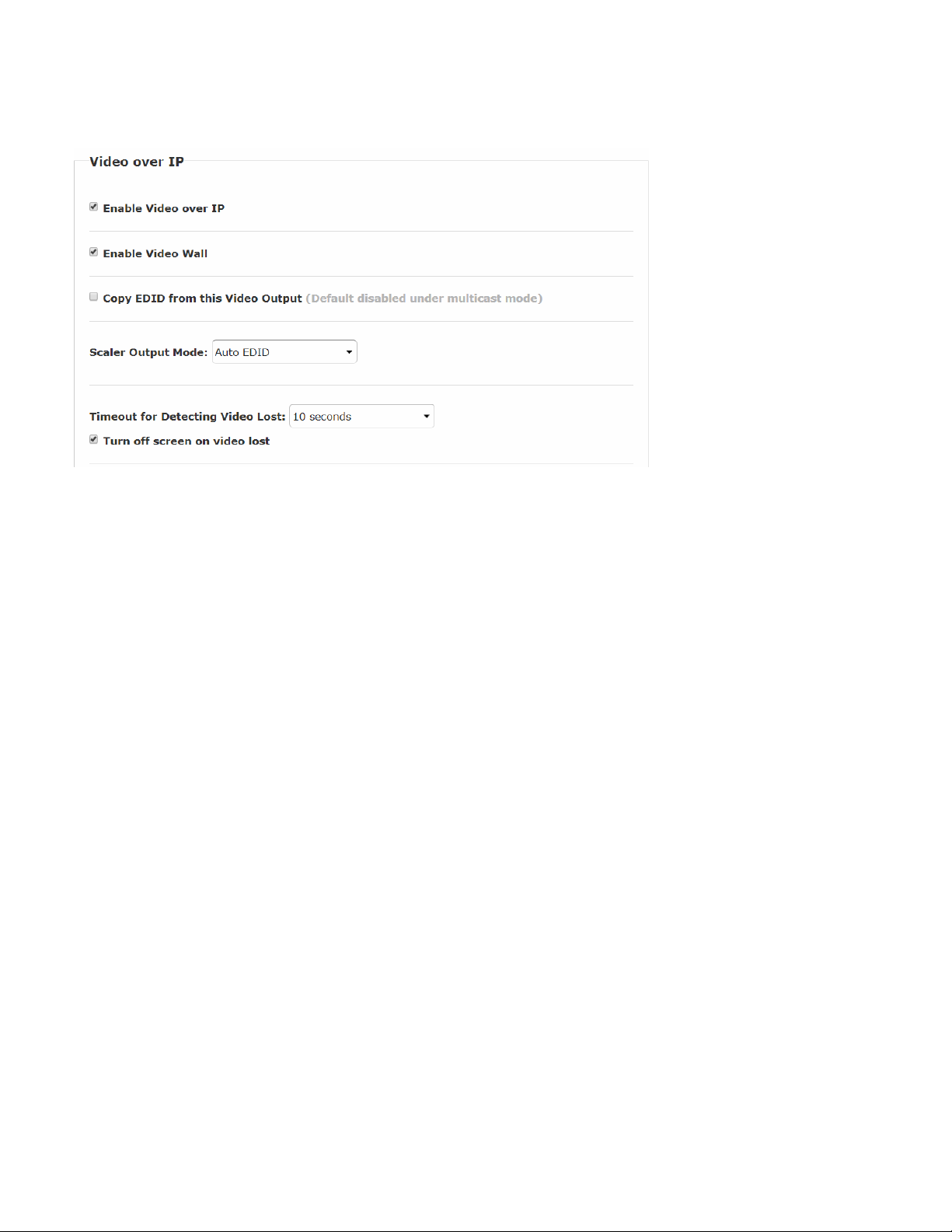
Video over IP (RX)
Functions ---> Video over IP :
Enable Video over IP (Default Enabled).
Enable Video Wall : Enable this setting for the Video Wall output.
Copy EDID from this Video Output : To assign this RX as the EDID Master.
Scaler Output Mode :The RX includes a scaler feature.
The output resolution can be selected from these options:
Auto EDID (default),
Pass Through,
2160p30, 2160p25, 1080p60, 1080p50, 1920x1200,
Customize.
Auto EDID means the RX will output to screen resolution according to screen’s EDID.
Timeout for detecting video lost :The timeout period for lost video detection (default 10 sec.)
Turn off screen on video lost : Stop the video output when video source is lost (default Enabled)
12
Page 15
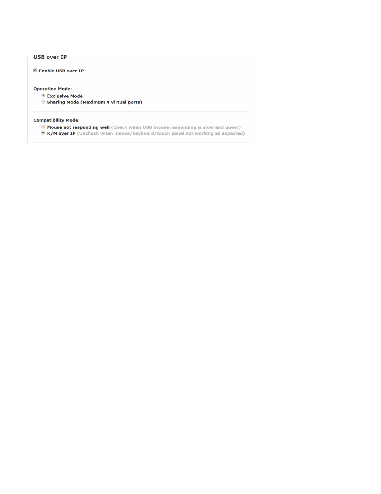
USB over IP (TX)
Enable USB over IP ---> Check to enable TX’s USB over IP feature (default Enabled). It works as a 5-port Virtual HUB when TX
is attached to a USB port on the PC. Up to 5 Virtual USB ports will be sequentially linked to the connected RX USB devices.
There are 4 USB ports on each RX, but only the ports with devices attached (up to 5 total) will occupy the TX’s Virtual USB port.
Operation Mode --->The TX USB-over-IP supports the following 2 operation modes:
Exclusive Mode: All of TX’s 5 Virtual USB ports will be exclusively assigned to the RX which has the USB access right.
The other RXs can request USB access right manually.
Sharing Mode: The TX’s 5 Virtual USB ports can be shared by multiple RXs. Depending on the number of USB
devices on each RX, it is possible to have maximum 5 RXs sharing the same TX’s Virtual USB. If more
than 5 devices are connected, the TX will randomly select the 5 ports that will work. The remaining
devices will be ignored.
Note: In Sharing Mode, using more than one mouse or keyboard at the same time from two different RXs will have
undesirable results, as the PC will try to respond to both.
Compatibility Mode
Mouse not responding well ---> enable this setting when mouse is slow and not very responsive.
K/M over IP ---> The TX also has built in K/M over IP HID emulation for multiple RXs to share the same TX’s
keyboard/mouse. This feature will occupy one TX’s Virtual USB port when it is enabled (default: Enabled).
13
Page 16
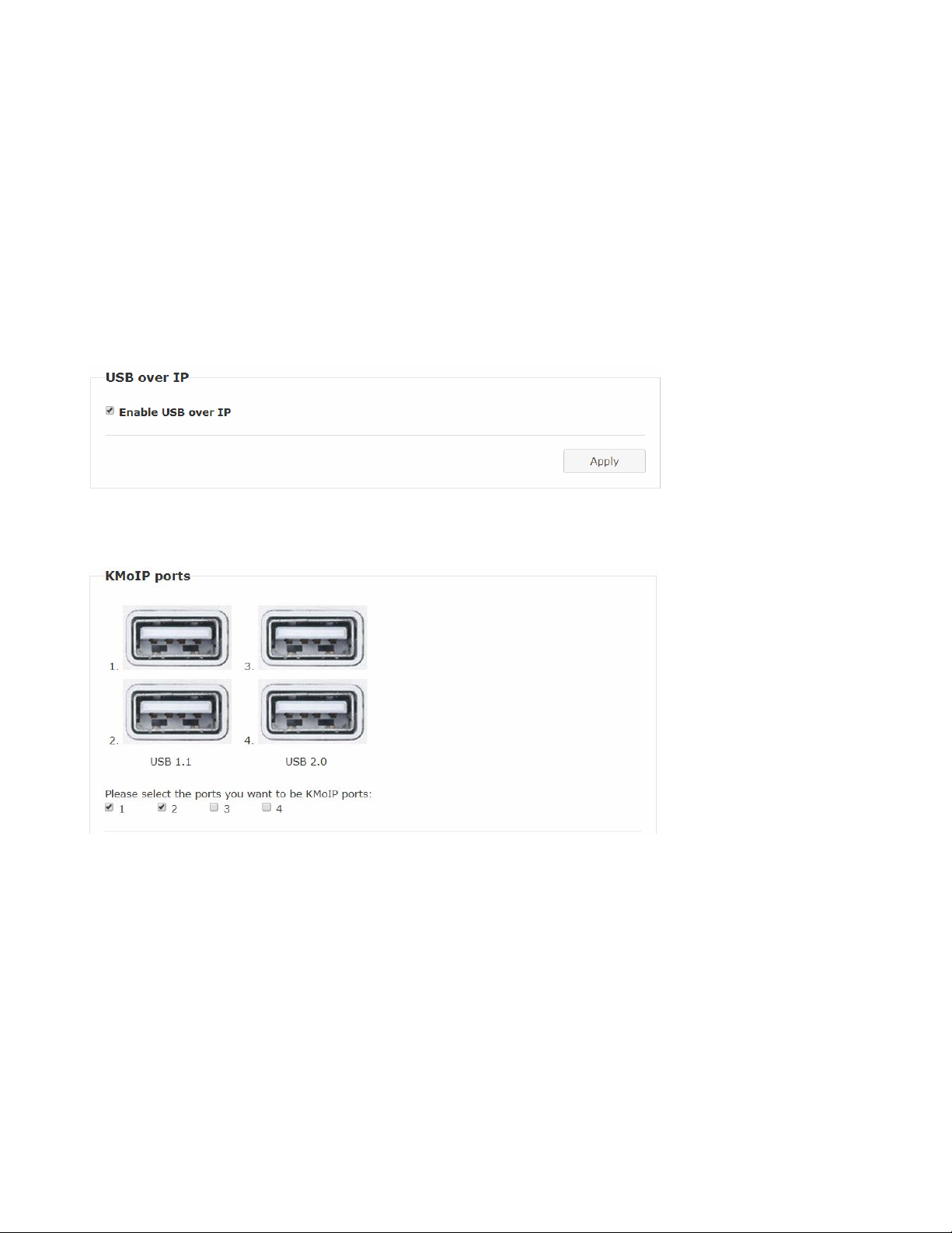
USB over IP KMoIP ports (RX)
There are 2 x USB 1.1 and 2 x USB 2.0 ports on each RX. These 4 USB ports can be configured for USB-over-IP or KM-over-IP
devices. The USB-over-IP devices will be virtually linked to the TX’s 5 VirtualUSB ports; the KM-over-IP devices will be linked and
shared with the TX’s K/M over IP HID emulation port.
The advantage of USB-over-IP device have better USB compatibility, for example USB Touch, Disk, … devices must be configured
with USB-over-IP. The advantage of KM-over-IP device is to have multiple RXs sharing the same TX’sK/M over IP HID emulation
port. It is recommended to configure the 2 x USB 1.1 (keyboard/mouse) as KMoIP ports and 2 x USB 2.0 as USB over IP ports (for
Touch, Disk).
The RX USB over IP Configuration Web page:
This USB over IP setting must be enabled for any USB devices to be attached with TX’s Virtual USB HUB.
The RX KMoIP ports Configuration Web page:
Enable the port #1, 2, 3, 4 for the device to be linked with the TX’s K/M over IP HID emulation port.Default Port 1 and 2 KMoIP
Enabled.
Note: All of RX’s 4 x USB ports will be configured as KMoIP if the USB over IP is disabled.
14
Page 17
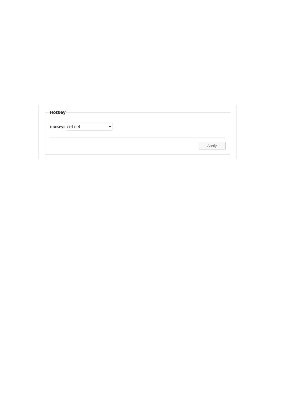
Hotkey (RX)
The RX supports Hotkey for OSD Menu.
To choose the RX OSD Hotkey:
Functions ---> Hotkey ---> select the Hotkey from the list: <Ctrl><Ctrl>, <Shift><Shift>, <Alt><Alt>, or <Scroll><Scroll>
(default: Ctrl Ctrl).
15
Page 18
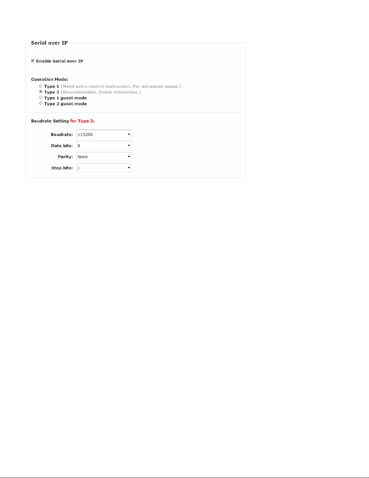
Serial over IP (TX/RX)
Serial over IP ---> Enable/Disable (default Enabled).
Operation Mode
Type 1: for Unicast application where user can dynamically link with any target RX.
Type 2: for Multicast application where TX RS-232 will link with all of connected RXs (default).
Type 1 guest: similar to type 1 but using PC to link with RX’s RS-232.
Type 2 guest: similar to type 2 but using PC to link with RX’s RS-232.
Baudrate Setting for Type 2
Set RS-232 Baudrate, Data bits, Parity, Stop bits. (default 115200, 8-n-1)
Point-to-Many connection via RS232
If one local unit pairs with multiple remote units, then point-to-many RS232 is supported.
When the Tx unit sends RS232 message, all Rx units receive the same message.
When multiple Rx units send an RS232 message at the same time, the fastest Rx will take control. The Tx unit
will only receive that Rx's message and reject messages sent from other Rx units. Once the controlling Rx stops
sending messages for about 1~2 seconds, the control authority will be released and all Rx units will be competing for
priority again.
16
Page 19
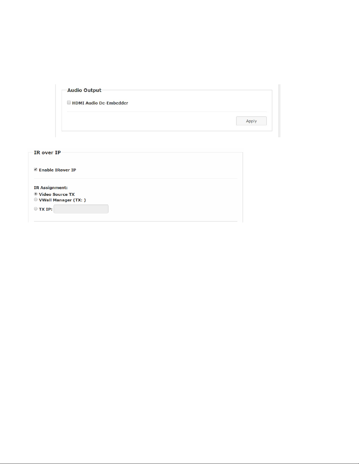
Audio Output (RX)
If the TX’s input audio is in HDMI, you can route the audio output on Line Out of the RX:
Functions ---> Audio Output ---> check “HDMI Audio De-Embedder”.
Click Apply to save the setting and reboot. (default Disabled)
IR over IP (RX)
It is possible to assign the IR signal routing path:
Enable IR over IP (default Enabled)
IR Assignment --->Select IR routing path from the following 3 options:
Video Source TX --->Send the RX’s IR input signals to the TX of current video source.
VWall Manager (TX: ) --->Not applicable
TX IP: --->Send the RX’s IR input signals to this specified TX.
17
Page 20
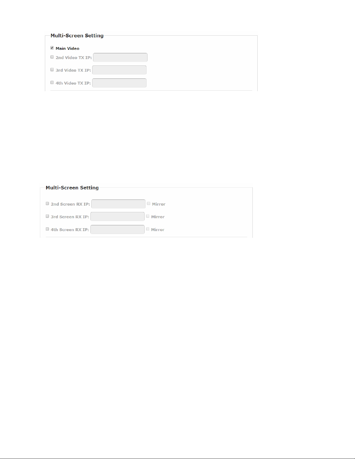
Multi-Screen Setting (TX)
The system supports Multi-Screen feature which is useful for PC with multiple screen outputs. As above TX Multi-Screen Setting
Web page:
Main Video : Enable this setting if this TX is connected to the PC’s main video output.
Note: Any TX with Main Video setting disabled will not be shown on the OSD Transmitter List.
nd
2
Video TX IP : Type in another TX IP address which is connected to the PC’s 2nd video output.
rd
3
Video TX IP : Type in another TX IP address which is connected to the PC’s 3rd video output.
th
4
Video TX IP : Type in another TX IP address which is connected to the PC’s 4th video output.
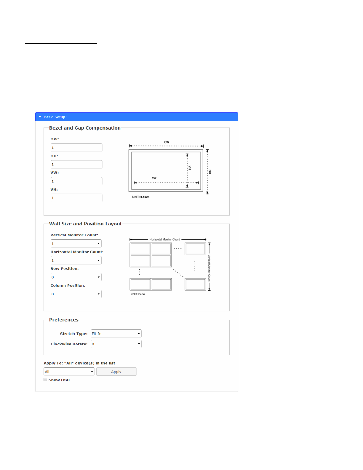
Multi-Screen Setting (RX)
Similar to the TX Multi-Screen Setting page, in the above RX Multi-Screen Setting Web page:
nd
2
ScreenRX IP : Type in another RX IP address which is connected to the 2nd screen.
rd
3
ScreenRX IP : Type in another RX IP address which is connected to the 3rd screen.
th
4
ScreenRX IP : Type in another RX IP address which is connected to the 4th screen.
When the Main RX switches to a new TX, its associated RXs will also be switched to the new TX’s associated TXs automatically.
Mirror (RX)
When the “Mirror” option is enabled, the associated RXs will connect to the same TX as the Main RX is connected to. This splitter
function enables multiple RXs to display the same TX.
18
Page 21
Video Wall Functions
Remote Unit function only (RX)
The RX comes with a Video-Wall feature. Multiple RXs can receive the same video stream and display on multiple screens in
a grid. You can setup the Video-Wall either by using OSD (On Screen Display) or the Web page.
The following section provides information for the Web page method of Video Wall setup.
19
Page 22
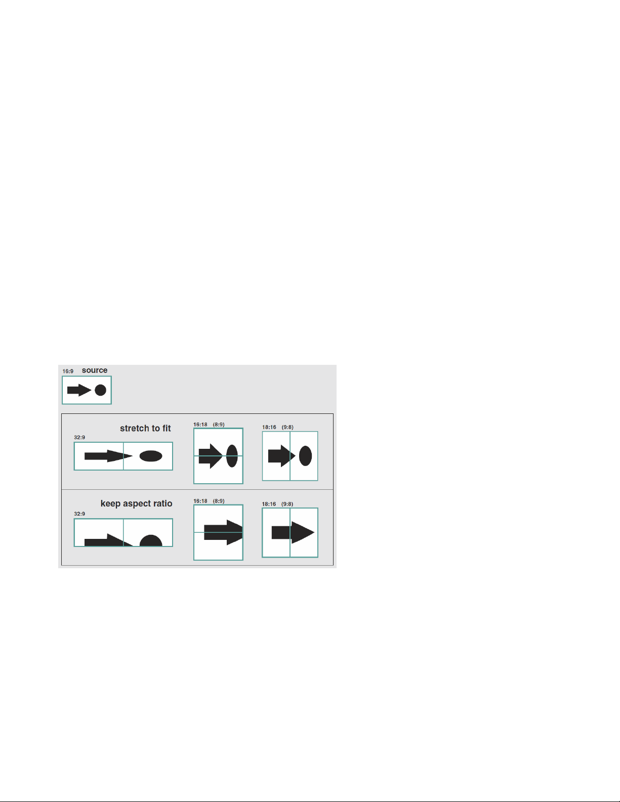
Basic Setup
Enter RX Web page ---> Video Wall ---> Basic Setup .
Bezel and Gap Compensation
Enter the value for OW (Outside Width), OH (Outside Height), VW (View Width), VH (View Height) in 0.1mm units ---> Apply .
Wall Size and Position Layout
Select the value for Vertical Monitor Count, Horizontal Monitor Count, Row Position, Column Position from the drop-down menu --> Apply .
Preferences
Stretch Type --->Select ”Fit In” or “Keep Aspect Ratio” ---> Apply
Clockwise Rotation ---> Select 0, 180, 270 --> Apply
Note:
Fit In: Stretches or compresses the broadcast screen to fill the whole wall.
Keep Aspect Ratio: keeps strict picture aspect ratio. If there is a mismatch, some image may fall beyond screen edges.
The following screenshot shows couple examples of Fit In and Keep Aspect Ratio:
Show OSD
To identify the screen, check the “Show OSD” and select the device then click Apply button.
20
Page 23
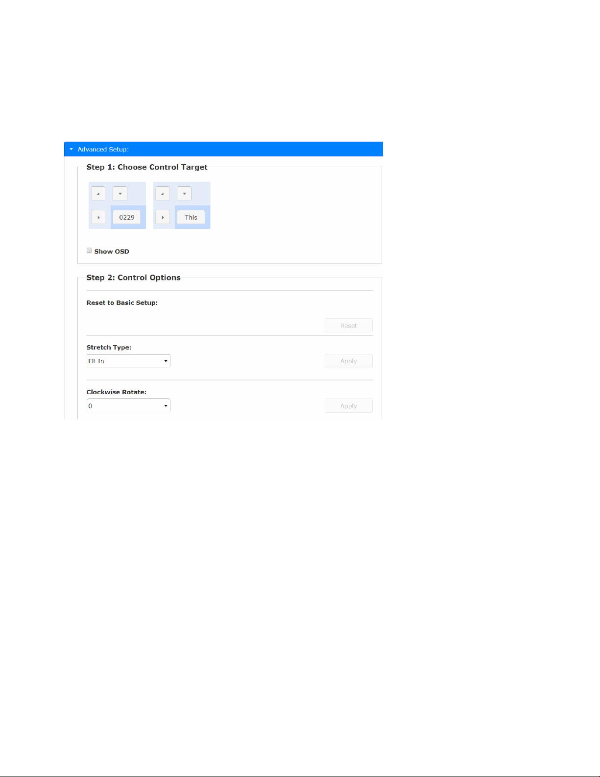
Video-Wall Advanced Setup
The Advanced Setup can be used for special effects which are not included in Basic Setup. There are two steps in advanced
setup:
Step 1: Choose one or more target RXs to apply setup to.
Step 2: After the targets are selected, changes can be applied in Step 2.
Show OSD
To identify the screen, check the “Show OSD” and select the device then click Apply button.
Reset to Basic Setup --->Reset the target(s) to the setting of “Basic Setup”.
Stretch Type
Fit In: Stretch the full screen to the whole wall.
Keep Aspect: keeps picture aspect ratio; some image may spill off screen if needed.
Clockwise Rotate
0: No rotation
180: clockwise rotate 180 degrees
270: clockwise rotate 270 degrees
21
Page 24
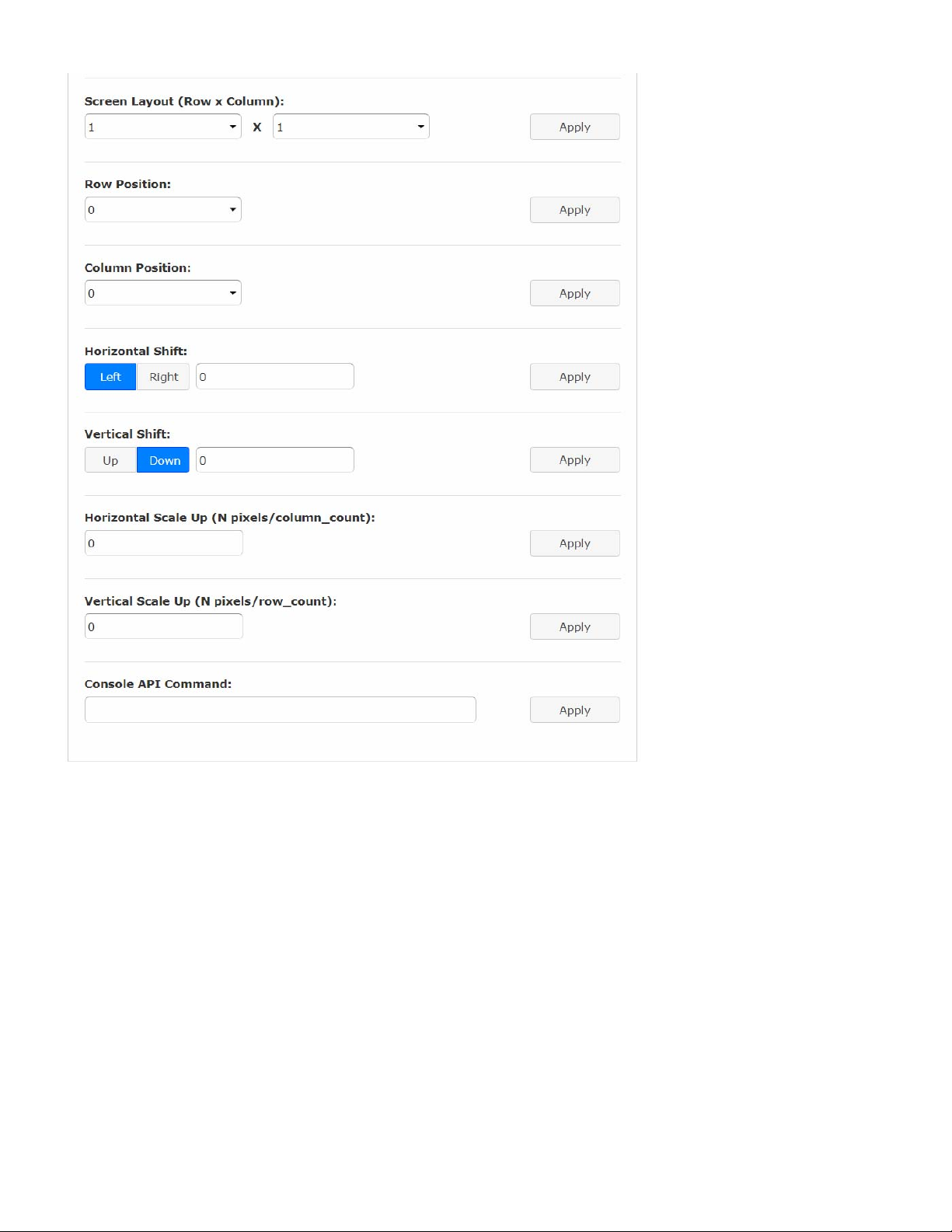
Screen Layout (Row x Column)
Define the Video Wall size, select the Row and Column count from the drop-down menu.
Row Position : Set the Row position for the selected target RX. (start from 0)
Column Position :Set the Column position for the selected target RX. (start from 0)
Horizontal Shift :Shift target screen horizontal to left/right in 1 pixel units.
Vertical Shift :Shift target screen vertically up or down in 1 pixel units.
Horizontal Scale Up (N pixels/column_count) : Scale up the target screen horizontally, by pixels (1/column count).
Vertical Scale Up (N pixels/column_count) : Scale up the target screen vertically, by pixels (1/row count).
22
Page 25

INSTALLATION(TX/RX)
1. The factory default Connection Method for RX is “First Available”, and TX is in Multicast mode with its default
Multicast IP (shown on the label). It means all TXs will send packets with default Multicast IP (225.0.10x.xxx), and
all RXs will find the first available TX for connection.
2. Use an Optical Fiber cable to directly connect TX/RX as a pair connection, or connect to an IGMP-enabl ed
Gigabit Ethernet switch for many-to-many installation.
Note: Each TX comes with individual factory default Multicast IP which is shown on the unit label.
3. Connect TX/RX to a video source/screen using an HDMI cable.
4. The TX factory default EDID setting is 1920x1080 @60Hz.
You can change TX to “Copy EDID from EDID Master“, and perform step 4.1/4.2 to assign a RX as the EDID
Master.
You can change TX to “Copy EDID from the 1
steps 4.3 or 4.4.
Or you can change and use the TX built-in EDID as instructed in step 4.5:
4.1 Press and hold the Mode button of the specific RX unit and power ON until Green LED blinking then
releasing the Mode button, this RX will be assigned as EDID Master (RX’s Green LED will blink, then steady
ON, and Amber LED Off to indicate it is ready and waiting for connecting with TX). Then power ON other RX
units sequentially.
4.2 Refer page 9, enable “Copy EDID from this Video Output” to assign a specific RX as EDID Master.
4.3 Refer page 6, enable “Copy EDID from 1
4.4 Refer page 6,enable “Copy EDID from RX IP” to set TX EDID from a specific RX.
4.5 To use TX built-in EDID for specific Resolution, refer to page 7 “Resolution Selection”.
5. The following start-up messages will be displayed during RX power on:
FW: 02-Jan-2019 A6.6.0.8 (Firmware date and version)
Local IP: 10.0.34.38 (RX’s IP address)
MAC: 0020FExxxxxx (RX’s MAC address)
Connection Method: First Available
Remote IP: 10.0.x.x/ 225.0.x.x (Connecting target TX IP / Multicast IP)
6. To get the best video performance, please refer to page 10 to enable TX/RX Jumbo Frame setting, and set
Ethernet Switch Jumbo Frame with minimum 8K bytes.
st
connected RX” or “Copy EDID from RX IP” and then perform
st
connecting RX” to set TX EDID from the first connected RX.
7. Attach HDMI/DVI source to the TX’s HDMI In. Then power ON the TX unit. The Green LED will blink , then go
steady ON to indicate ready and waiting for connecting with RX.
8. Until TX/RX connection is established, both TX and RX Amber LED will start to blink, indicating waiting for video
input source (Green LED is ON).
9. If you are using PC as video source, verify the correct screen EDID is shown on PC's graphic control panel.
10. Activate the video with audio source connected to TX, then check if all RXs are correctly displayed. In this step,
both Green and Amber LEDs should now be ON to indicate the unit is ready and video sou rce is also ready.
USB over IP and KM over IP installation
11. Connect TX USB-B port to the PC, the OS will detect a Generic USB 2.0 Virtual Hub Device.
12. Refer to the USB over IP , K/M over IP and KMoIP ports on page 13 to properly configure TX and RX for the
USB devices such as keyboard, mouse, Pen Drive, Touch Screen, etc.
Note: The RX KMoIP ports will be linked to TX’s KM over IP HID emulation; RX USB-over-IP ports will be linked
to TX’s Virtual USB ports.
It is not necessary to gain USB access rights for the KMoverIP port. The TX (PC) can be shared with multiple
RXs for keyboard/mouse access in KMoverIP mode.
13. There are 4 USB-A ports on the RX. The factory default setting for the TX is both USB-over-IP and KM-over-IP
enabled; all 4 RX USB ports are USB-over-IP enabled and KM-over-IP disabled.
23
Page 26
14. There are 2 methods to gain the access rights for a USB-over-IP port:
14.1 Pressing and hold for 3 sec.the RX Link button .
14.2 Press “U” key to toggle when the Transmitter List OSD menu is displayed.
The RX monitor will display “Requesting USB” to indicate starting a USB-over-IP connection, and message of
“Starting USB” will be displayed if it successfully gained the USB access rights. Meanwhile, the previous USB
Master unit will show an OSD message of “USB Stopping”.
24
Page 27
25
Page 28
Panel Button and Hotkey Operation
Press TX “Button 1” button to lock/unlock RX
Keep pressing TX “Button 1” button for 3 seconds to lock/unlock the RX’s USB and KMoIP ports. The RX will display “Locked by
TX” OSD message on the screen when it is locked.
Press TX “Button 2” or RX “Mode” button to select Video/Graphic mode
Press TX “Button 2” or RX “Mode” button to set RX in Video or Graphic mode. The RX will display “Graphic Mode” or “Video
Mode” OSD message on the screen.
Press and hold RX “Link” button for 3 seconds to request/release USB access rights
The RX user can manually request/release USB access rights when a TX is connected with multiple RXs. Press and hol d RX
“Link” button for 3 seconds to request USB access rights, the RX will display “Starting USB” OSD message. Pressing again will
release and display “Stopping USB”.
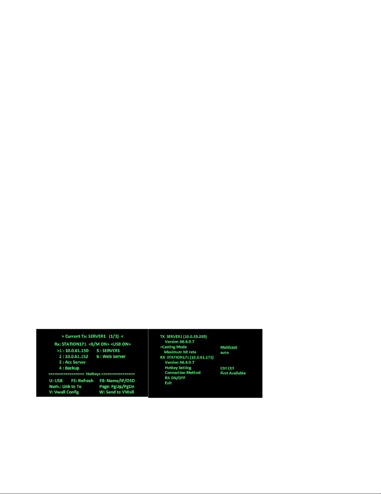
Press RX “Link” button for the “Transmitter List” and “Simple Configuration” OSD Menu
Press RX’s “Link” button for the Transmitter List OSD Menu as shown in the below left screenshot. Briefly press the button again
to move the highlighting arrow“>”to select the TX. The RX will connect to the selected TX after 3 seconds.
From the Transmitter List OSD Menu, press and hold the “Link” button for 3 secon
Menu as shown in the below right screenshot. Briefly press the button to move the highlighting arrow“>” to select the settings to
change. You can change Casting Mode, TX Maximum bit rate, Connection Method and RX ON/OFF (temporary
Connect/Disconnect with TX).
Move the highlighting arrow “>”to Hotkey Setting , wait a few seconds, and a sub-menu will show up wit h 4 possible selections:
“Ctrl Ctrl”, “Shift Shift”, “Alt Alt”, or “Scroll Scroll”. Press the “Link” button to move the highlighting arrow “>”to the desired
selection. The RX unit will be re-booted.
ds to enter the Simple Configuration OSD
RX“TransmitterListOSDMenu”byHotkey
Pressing<hotkey><hotkey>attheRXkeyboardwillactivatetheTransmitterListOSDMenuwithamaximumof8
Transmittersperpage,asshowninthescreenshotbelow.Thetop2linesarethecurrentTXandRXIPorname.Youcan
selecttheTXbypressingth
e↑↓keys,thenpress<Enter>toconnecttotheselectedTX.Youcanalsopresskeys1~8to
immediatelyconnecttothetargetTX.
26
Page 29
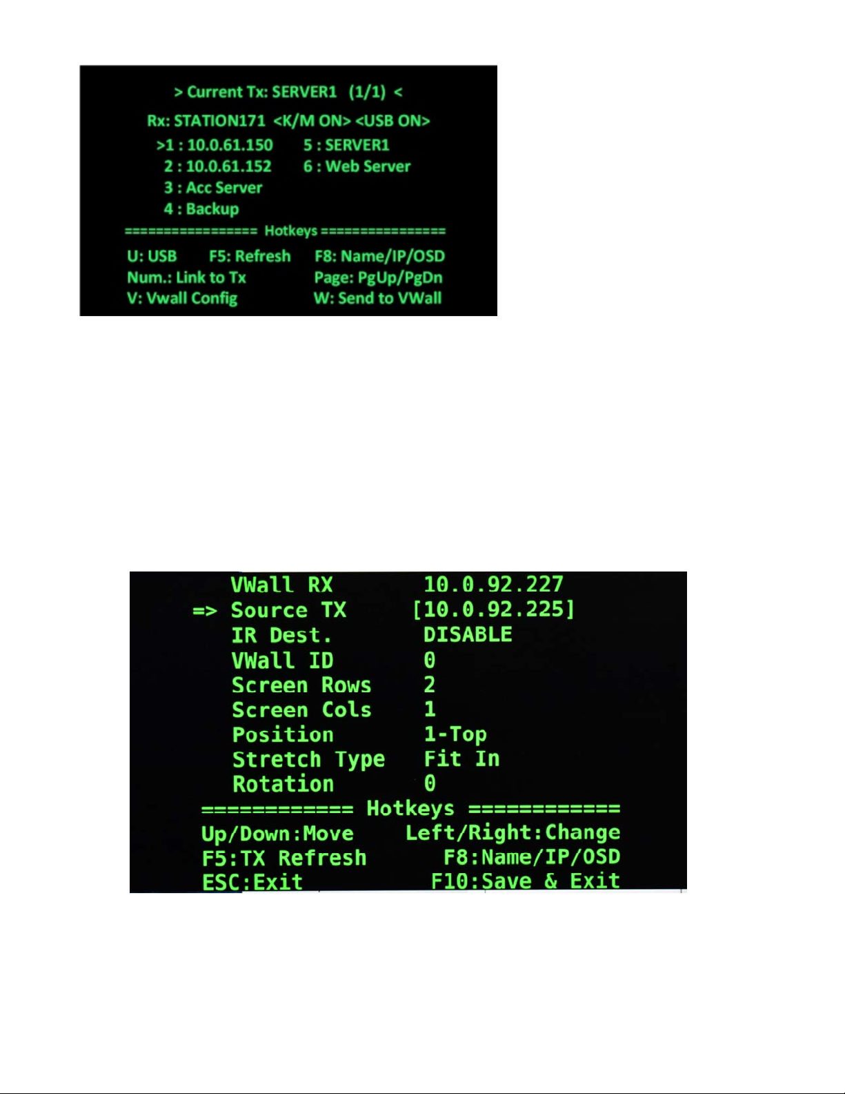
While in the Transmitter List OSD Menu, you can:
Press U to request/release USB-over-IP.
Press F5 to refresh the Transmitter List.
Press F8 to switch in between Name/IP/OSD modes.
Press V to enter Video-Wall configuration.
Press W to send the current display to other RX or RXs with VWall ID.
While the Video Wall OSD menu is up (below), the characteristics of the RX with the video wall can be adjusted as needed. Keys
to press for the desired changes are indicated at the bottom of the menu.
Don't forget to press <F10> to save any changes you make before you exit.
To exit the OSD without saving, press<ESC>
27
Page 30

SPECIFICATIONS
Local Unit
Compatible with a USB computer (PC, SUN and MAC) with Ultra-HD HDMI output.
Multiplatform support: Windows 2000/XP/Vista/7/8/10, Windows Server 2000/2003/2008/2012, Solaris, Linux, FreeBSD,
and MAC OS 9/10.
One female HDMI connector for source.
One female HDMI connector for display.
One female USB Type B connector.
Two female 3.5mm stereo jacks for audio out and mic in.
Speaker only works when in a point-to-point connection.
One female 3.5mm port for IR emitter (sold separately).
Screw terminal for RS232.
One duplex female LC fiber optic port for sending video/audio, USB, IR, and RS232 signals.
Remote Unit
One female HDMI connector.
Four female USB Type A connectors for keyboard, mouse, flash drive, HDD, or touchscreen display.
Two USB 2.0 and two USB 1.1
Two female 3.5mm stereo jacks for audio out and mic in.
Microphone only works when in a point-to-point connection.
One female 3.5mm port for IR receiver (sold separately).
Screw terminal for RS232.
One duplex female LC fiber optic port for sending video/audio, USB, IR, and RS232 signals.
Supported video resolutions:
Ultra-HD 4Kx2K resolutions (3840x2160 @ 30Hz)
2K Cinema (2048x1080 @ 60Hz)
HDTV resolutions to 1080p
Up to 1920x1200 (WUXGA)
Supports embedded digital audio through HDMI compatible TVs or audio receivers.
RS232
Supports TXD and RXD.
Baud rate: 9600/14400/19200/38400/57600/115200.
Power
Local and Remote unit:
o Input: 100 to 240 VAC at 50 or 60 Hz via AC adapter (included).
o Output: 12 VDC, 2A
Dimensions
WxDxH (in): 6.1x4.33x1.18 (155x110x30 mm).
28
Page 31

Enviro
nmental
Operating temperature: 32 to 122°F (0 to 50°C).
Storage temperature: -4 to 185°F (-20 to 85°C).
Operating/storage relative humidity: 0 to 80% non-condensing RH.
Regulatory Approvals
RoHS
TAA compliant
Max Distance
Using singlemode 9-micron cable, extend to 9,842 feet (3,000 meters).
Using multimode 50-micron cable, extend to 1,804 feet (550 meters).
WARRANTY INFORMATION
The warra
Technologies Inc at (800) 742-8324 (800-RGB-TECH) or (330) 562-7070 or visit our website at http://www.networktechinc.com for
information regarding repairs and/or returns. A return authorization number is required for all repairs/returns.
nty period on this product (parts and labor) is two (2) years from the date of purchase. Please contact Network
MAN374 Rev. 6/5/20
29
 Loading...