

Page 1
®
XTENDEX
Series
ST-C64K18GB-197
HDMI18GbpsExtenderwithone‐wayIR
InstallationManual
Page 2

TRADEMARK
XTENDEX is a registered trademark of Network Technologies Inc in the U.S. and other countries.
COPYRIGHT
Copyright © 2019 by Network Technologies Inc. All rights reserved. No part of this publication may be reproduced, stored in a retrieval
system, or transmitted, in any form or by any means, electronic, mechanical, photocopying, recording, or otherwise, without the prior
written consent of Network Technologies Inc, 1275 Danner Drive, Aurora, Ohio 44202.
CHANGES
The material in this guide is for information only and is subject to change without notice. Network Technologies Inc reserves the right to
make changes in the product design without reservation and without notification to its users.
Note: CATx connection cable used between NTI XTENDEX Series Transmitter and Receiver or any XTENDEX
Series products should not be run underground, outdoors or between buildings.
WARNING: Outdoor or underground runs of CATx cable could be dangerous and will void the warranty.
WARNING: The CATx connection cable used between NTI XTENDEX Series Transmitter and Receive r or any
XTENDEX Series products must be wired straight through (pin 1 to pin 1, pin 2 to pin 2, etc.) The use of a
CROSSOVER CABLE will damage the extender and void your warranty.
TableofContents
Introduction ............................................................................................................................................................ 1
Features................................................................................................................................................................... 1
MaterialsSupplied .................................................................................................................................................. 1
PreparationforInstallation..................................................................................................................................... 2
FeaturesandFunctions ........................................................................................................................................... 3
Transmitter Panel......................................................................................................................................3
Receiver Panel..........................................................................................................................................4
IR Pin Definition.........................................................................................................................................5
Application Example..................................................................................................................................6
Specifications .......................................................................................................................................................... 7
InterconnectionCable............................................................................................................................................. 8
NTIHDMICablesCompatiblewiththeExtender.................................................................................................... 8
WarrantyInformation ............................................................................................................................................. 9
Page 3

Introduction
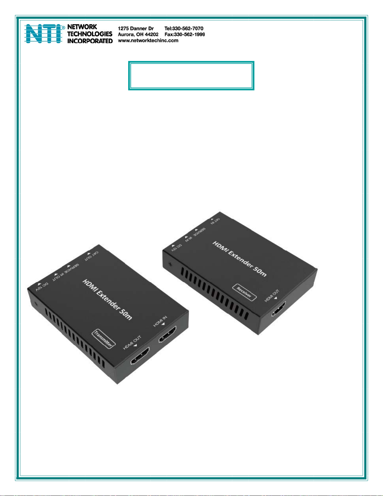
The ST-C64K18GB-197 HDMI 18Gbps Extender can extend high definition video / audio signal and one-wa y IR up to 197ft
/ 60 meters over a single Cat6/6a/7 cable (up to 164 feet (50m) with CAT5e). It supports resolutions up to
4K2K(3840x2160)@60Hz 4:4:4, 18Gbps and HDCP 2.2. In addition, the extender is equipped with one-way IR
pass-through which allows for source control and one HDMI loop output.
The XTENDEX includes two units: Transmitter unit and Receiver unit. The Transmitter unit carries an HDMI input signal to
the Receiver via one cost effective Cat5e/6/6a/7 cable. The Receiver will also sends a n IR control signal from a video
source remote to the Transmitter, enabling extended control of the video source.
Features
☆
HDMI 2.0, HDCP 2.2 / HDCP 1.4 and DVI 1.0 compliant
☆
Supports 18Gbps bandwidth
☆
Supports input and output video resolution up to 4k2k@60Hz 4:4:4, extends distance up to 197ft (60
meters)
☆
Supports one HDMI loop output
☆
Supports one-way IR pass-through
☆
Supports HDR function
☆
Supports PoC (Power over Cable) function, meaning that if either the Transmitter or Receiver is powered by the 12V/1A
power adapter, the other does not need a power supply.
☆
Supports automatic copy EDID function
☆
Compact design for easy and flexible installation.
MaterialsSupplied
1× HDMI 18Gbps XTENDEX Transmitter
1× HDMI 18Gbps XTENDEX Receiver
1× IR Blaster cable (1.5 meters)
1× 20~60KHz IR Receiver cable (1.5 meters)
1× 100-240VAC 50/60Hz ; 12VDC/1A Locking Power adapter
4× Mounting Ears
1× URL slip with path to this manual
Additional materials may need to be ordered, depending upon the configuration:
CAT5e/6/6A/7 unshielded twisted-pair cable(s) terminated with RJ45 connectors wired st raight thru- pin 1 to pin 1, etc. (se e
pg. 8 for proper EIA/TIA 568 B wiring method)
Contact your nearest NTI distributor or NTI directly for all of your KVM needs at 800-RGB-TECH (800-742-8324) in US &
Canada or 330-562-7070 (Worldwide) or at our website at
assistance.
http://www.networktechinc.com and we will be happy to be of
1
Page 4

PreparationforInstallation
Locations should be chosen for the monitors, mice, and keyboards that also have space to connect the Remote and
Local Units within the distance provided by the cables. If extension cables are needed, contact NTI for the cables
required.
The CATX cables must be run to the locations where the Remote and Local Units will be connected. Be careful to route
the cables away from any sources of magnetic fields or electrical interference that might reduce the quality of the video
signal (i.e. AC motors, welding equipment, etc.).
All cables should be installed in such a way that they do not cause stress on their connections to the equipment.
Extended lengths of cable hanging from a connection may interfere with the quality of that conn ection. Secure cables
as needed to minimize this.
Properly shut down and disconnect the power from the CPU and monitors to be separated. If other equipment is
involved whose connections are being interrupted, be sure to refer to the instruction manuals for that equipment for
proper disconnection and re-connection procedures before proceeding.
Local and Remote Units should be grounded through either a display or source that uses a 3-prong power co rd. If only
one unit is grounded, shielded CAT5 cable should be used.
Note: CATX connection cable used between NTI XTENDEX Series Local and Remote or any XTENDEX Series
products should not be run underground, outdoors or between buildings.
WARNING: Outdoor or underground runs of CATX cable could be dangerous and will void the warranty.
2
Page 5
FeaturesandFunctions
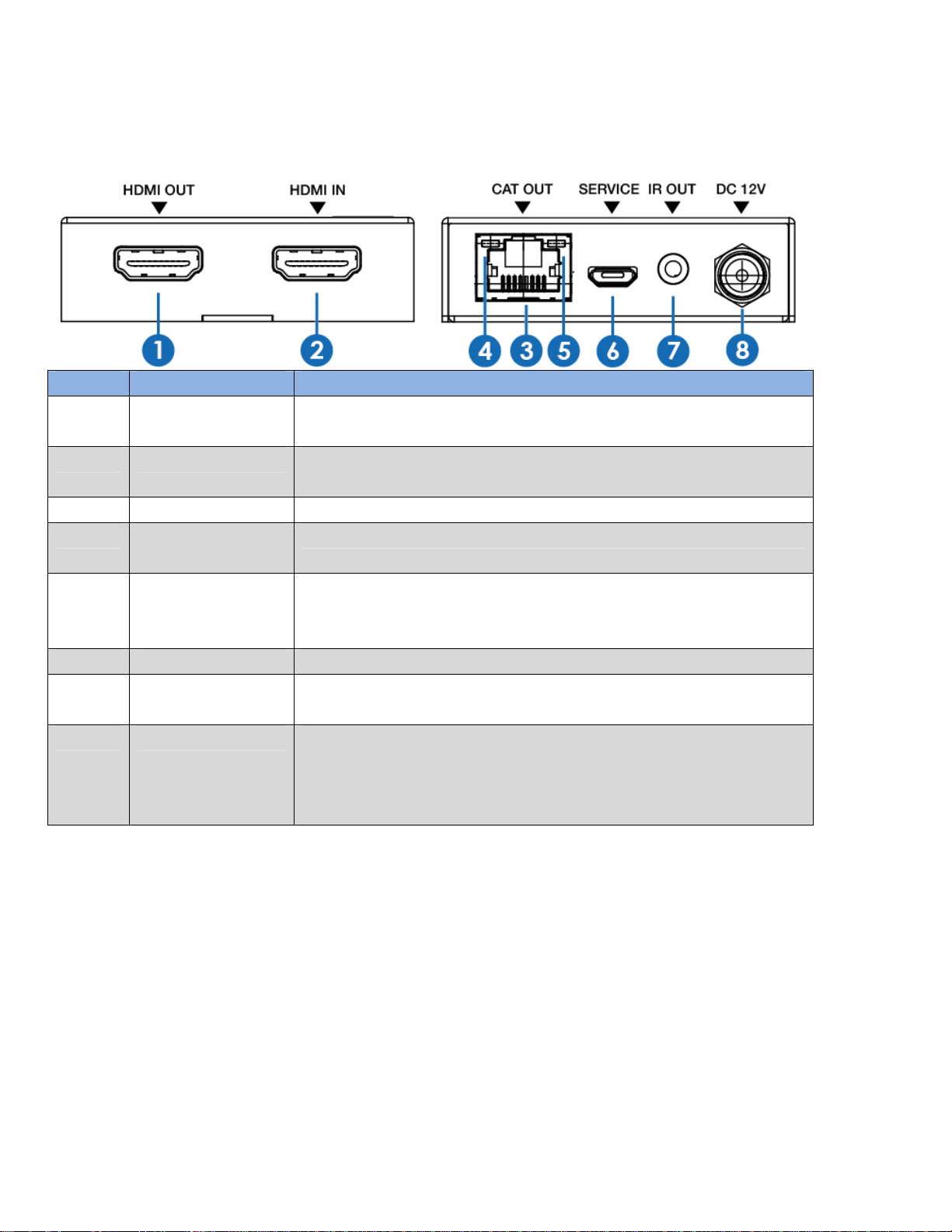
Transmitter Panel
Number Name Function description
1 HDMI OUT Connect to HDMI display device such as TV or Projector with an HDMI
cable.
2 HDMI IN Connect to HDMI source device such as DVD or PS4 player with an HDMI
cable.
3 CAT OUT Connect CAT6 cable between this and "CAT IN" port on the Receiver
4 Power Indicator
Lamp (Green)
5 Data signal
Indicator Lamp
(Orange)
6 SERVICE port For firmware update use.
7 IR OUT Connect wideband IR Blaster cable here. The IR signal is from the IR IN
8 DC 12V Plug 12VDC/1A power supply into the unit and connect the adapter to an
The lamp will illuminate when the Transmitter is powered ON.
The lamp will illuminate when the Transmitter and the Receiver have
signal transmission.
port of the Receiver.
AC outlet.
(Note: The extender supports PoC function; If the power supply is used for
the Transmitter, the Receiver does not require one)
3
Page 6
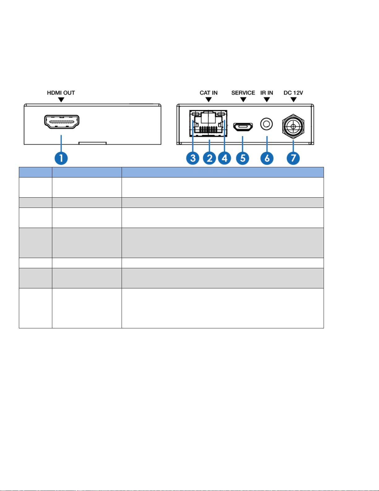
Receiver Panel
Number Name Function description
1 HDMI OUT Connect to HDMI display device such as TV or Projector with an HDMI
cable.
2 CAT IN Connect CAT6 cable from "CAT OUT" port on the Transmitter.
3 Power Indicator
Lamp (Green)
4 Data signal
Indicator Lamp
(Orange)
5 SERVICE port For firmware update use.
6 IR IN Connect wideband IR Receiver cable here. The IR signal will be se nt to
7 DC 12V Plug 12VDC/1A power supply into the unit and connect the adapter to an
The lamp will illuminate when the Receiver is powered ON.
The lamp will illuminate when the Transmitter and the Receiver have
signal transmission.
the IR OUT port of the Transmitter.
AC outlet.
(Note: The extender supports PoC function; If the power supply is used
for the Receiver, the Transmitter does not require one)
4
Page 7
IR Pin Definition
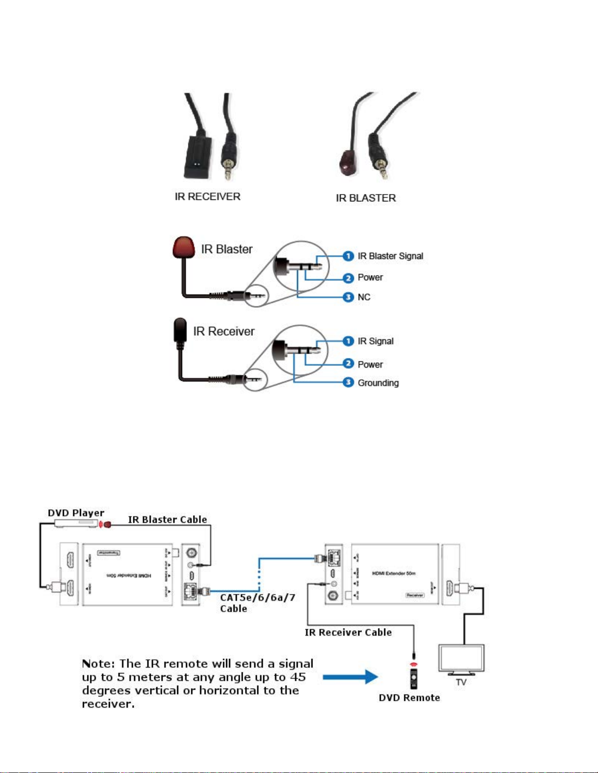
The IR Receiver and IR Blaster cables have pinout definition as shown below:
The following illustrates the IR system and how the IR cables are used.
5
Page 8
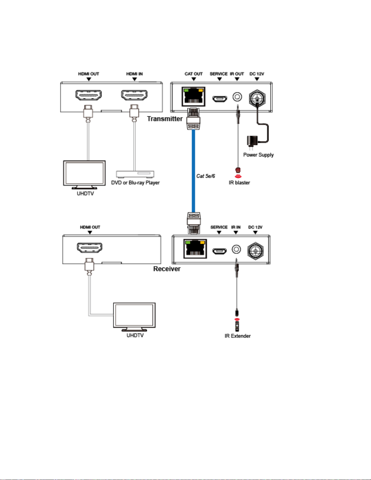
Application Example
6
Page 9

Specifications
Technical
HDMI Compliance HDMI 2.0
HDCP Compliance HDCP 2.2 / HDCP 1.4
Video Bandwidth 18Gbps
Video Resolution Up to 4K60Hz 4:4:4 (3840X2160@60Hz)
Color Space RGB / YCbCr 4:4:4, YCbCr 4:2:2/4:2:0, YUV 4:4:4
Color Depth 8/10/12-bit (1080P60Hz, 4K30Hz, 4K60Hz YCbCr 4:2:2/4:2:0)
HDMI Audio Formats LPCM 2.0/2.1/5.1/6.1/7.1, Dolby Digital, Dolby
ESD Protection Human body model — ±8kV (Air-gap discharge) &±4kV (Contact
Connections
Transmitter Inputs: 1x HDMI Type A [19-pin female]
Receiver Inputs: 1x IR IN [3.5mm Stereo Mini-jack]
Mechanical
Housing Metal Enclosure
Color Black
Dimensions WxDxH (In.) Transmitter / Receiver: 2.40x3.46x0.71 (61x88x18 mm)
Weight Transmitter: 160g, Receiver: 155g
Power Supply Input: 100-240VAC 50/60Hz
Power Consumption 4.44 W
Operating Temperature 32 - 104°F / 0 - 40°C
Storage Temperature -4 - 140°F / -20 - 60°C
Relative Humidity 20 - 90% RH (no condensation)
Resolution / Distance 4K60 (3840x2160)
CAT5e 100ft / 30M 164ft / 50M
CAT6/6a/7 197ft / 60M 230ft / 70M
HDMI IN/OUT See chart on next page
The use of “Premium High Speed HDMI” cable is highly recommended.
8-bit (4K60Hz 4:4:4 )
TrueHD, Dolby Digital Plus(DD+), DTS-ES, DTS
HD Master, DTS HD-HRA, DTS-X
discharge)
1x SERVICE [Micro USB, Firmware Update port]
Outputs: 1x HDMI Type A [19-pin female]
1x IR OUT [3.5mm Stereo Mini-jack]
1x CAT OUT [RJ45, 8-pin female]
1x CAT IN [RJ45, 8-pin female]
1x SERVICE [Micro USB, Firmware Update port]
Outputs: 1x HDMI Type A [19-pin female]
Output: 12VDC/1A
4K30 (3840x2160)/ 1080P -
Feet / Meters
Feet / Meters
7
Page 10
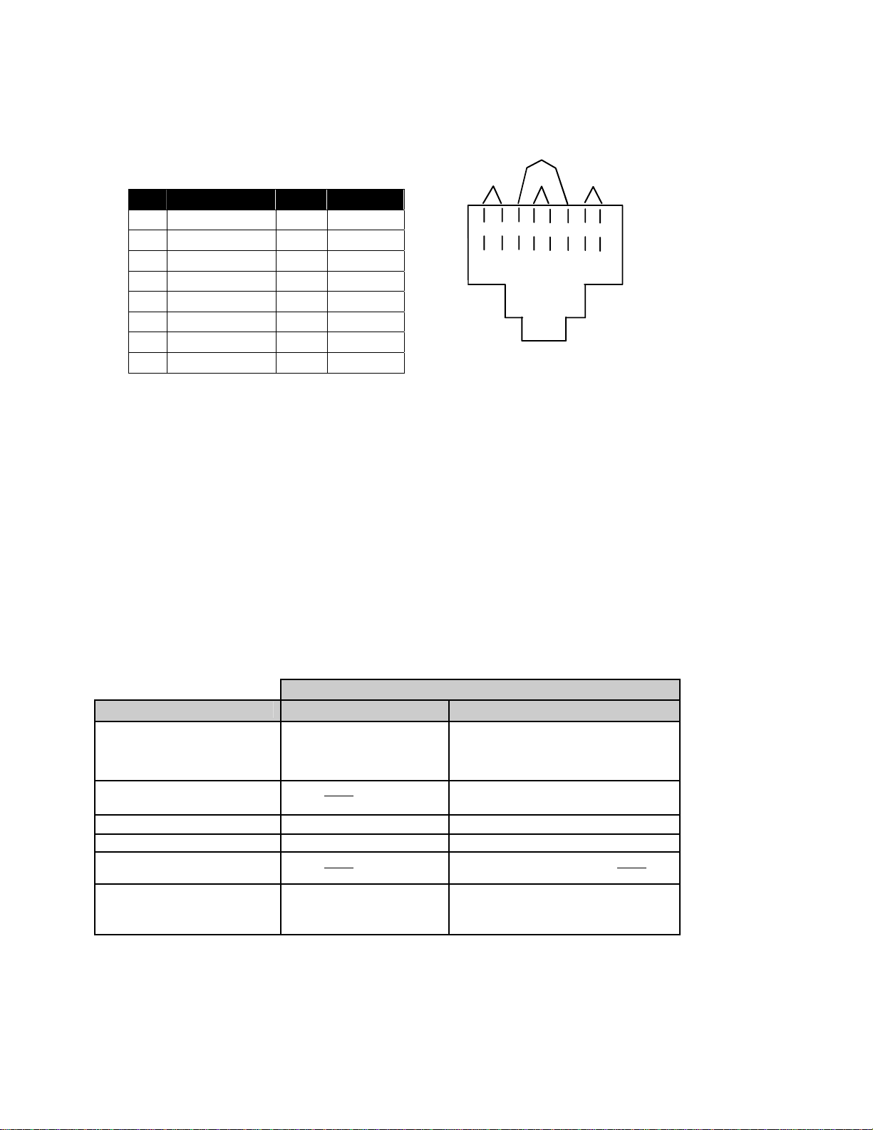
InterconnectionCable
The connection cable between the Transmitter and Receiver is terminated with RJ45 connectors and must be wired
according to the EIA/TIA 568 B industry standard. Wiring is as per the table and drawing below.
Pin Wire Color Pair Function
1 White/Orange 2 T
2 Orange 2 R
3 White/Green 3 T
4 Blue 1 R
5 White/Blue 1 T
6 Green 3 R
7 White/Brown 4 T
8 Brown 4 R
Pair 2 Pair 1
T
1
+
View looking into RJ45 female
Pair 3
Pair 4
T
R
R
T
3
2
4
5
+
-
-
+
R
R
T
8
6
7
+
-
-
NTIHDMICablesCompatiblewiththeExtender
Cables can be used on the Input (video source) or Output (display) unless otherwise indi cated.
Resolution supported
NTI # 1080p@60Hz 3840x2160
HD-xx-MM (Standard)
Where xx =
3,6,10,15,20,30 or 50ft
HD-xx-MM (Active)
Where xx = 75,100ft
HD-ACT-50-MM 50 ft 50 ft (@30/60Hz)
HD-ACT-100-MM 100 ft 100 ft (@30Hz)
HD4K18GB-FO-100M-MM Input Only 100 m (@30/60Hz) Input Only
DVI-HD-xM-MM
Where x = 1,2,3 or 5
meters
Up to 50 ft 30 ft (@30Hz)
20 ft (@60Hz)
Input Only No
Up to 5 meters No
8
Page 11

WarrantyInformation
The warranty period on this product (parts and labor) is two (2) years from the date of purchase. Please contact Network
Technologies Inc at (800) 742-8324 (800-RGB-TECH) or (330) 562-7070 o r visit our website at
http://www.networktechinc.com
for all repairs/returns.
Note: CATx connection cable used between NTI XTENDEX Series Transmitter and Receiver or any XTENDEX
Series products should not be run underground, outdoors or between buildings.
WARNING: Outdoor or underground runs of CATx cable could be dangerous and will void the warranty.
WARNING: The CATx connection cable used between NTI XTENDEX Series Transmitter and Receive r or any
XTENDEX Series products must be wired straight through (pin 1 to pin 1, pin 2 to pin 2, etc.) The use of a
CROSSOVER CABLE will damage the extender and void your warranty.
for information regarding repairs and/or returns. A return authorization number is required
MAN362 Rev 12/2/19
9
 Loading...