

Page 1
NTI
NETWORK
R
TECHNOLOGIES
INCORPORATED
1275 Danner Dr
Aurora, OH 44202
www.networktechinc.com
Tel:330-562-7070
Fax:330-562-1999
XTENDEX
EXTENDERS
Installation and Operation Manual
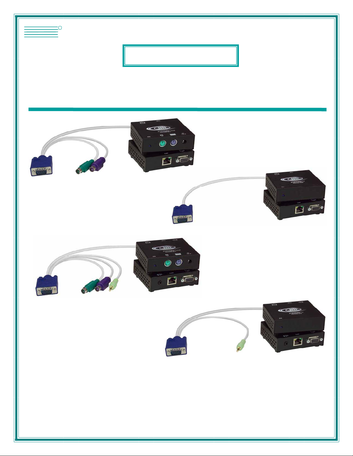
ST-C5KVM-300
PS/2 KVM Extender
ST-C5KVMA-300
PS/2 KVM and Audio
Extender
®
Series
ST-C5V-300
Video Extender
ST-C5VA-300
Video and Audio
Extender
MAN074 Rev Date 10/23/2013
Page 2

TRADEMARK
XTENDEX is a registered trademark of Network Technologies Inc in the U.S. and other countries.
COPYRIGHT
Copyright © 2005,2013 by Network Technologies Inc. All rights reserved. No part of this publication may be reproduced, stored
in a retrieval system, or transmitted, in any form or by any means, electronic, mechanical, photocopying, recording, or otherwise,
without the prior written consent of Network Technologies Inc, 1275 Danner Drive, Aurora, Ohio 44202.
CHANGES
The material in this guide is for information only and is subject to change without notice. Network Technologies Inc reserves the
right to make changes in the product design without reservation and without notification to its users.
Note: Shielded
requirements.
CAT 5,5e, or 6 cable must be used to connect to LOCAL and REMOTE units in order to meet CE emission
i
Page 3

TABLE OF CONTENTS
Introduction......................................................................................................................................................................1
Materials..........................................................................................................................................................................1
Features and Functions...................................................................................................................................................2
Limitations .......................................................................................................................................................................3
Preparation for Installation ..............................................................................................................................................4
Installation .......................................................................................................................................................................5
Installing The Remote Unit ..........................................................................................................................................5
Connect the CAT5 cable..............................................................................................................................................7
Installing The Local Unit ..............................................................................................................................................8
Connect The CAT5 Cable..........................................................................................................................................11
Plug-in and Boot Up...................................................................................................................................................11
Video Quality Adjustment..............................................................................................................................................12
Technical Specifications................................................................................................................................................13
Interconnection Cable Wiring Method...........................................................................................................................14
Troubleshooting.............................................................................................................................................................14
Index..............................................................................................................................................................................15
Warranty Information.....................................................................................................................................................15
TABLE OF FIGURES
Figure 1- Connect the Extended Components to the Remote Unit....................................................................................................5
Figure 2- Connect speakers to the Remote Unit................................................................................................................................6
Figure 3- Connect the extended components to the Remote Unit.....................................................................................................6
Figure 4- Connect the CAT5 cable to the Remote Unit......................................................................................................................7
Figure 5- Connect the local user to the XTENDEX Local Unit...........................................................................................................8
Figure 6- Connect speakers to Local Unit with audio support............................................................................................................8
Figure 7- Connect the local user with touchscreen monitor to the Local Unit ....................................................................................9
Figure 8- Connect the Local Unit with VGA video and audio support to the CPU............................................................................10
Figure 9- Connect the Local Unit with RS232 support to the CPU...................................................................................................10
Figure 10- Connect CAT5 cable to Local Unit..................................................................................................................................11
Figure 11- Connect the AC adapter to the Local Unit ......................................................................................................................11
Figure 12- Connect the AC adapter to the Remote Unit ..................................................................................................................12
Figure 13- Turn "Video Adjust" screw for video quality adjustment..................................................................................................12
Figure 14- View looking into RJ45 female........................................................................................................................................14
ii
Page 4
NTI XTENDEX 300 Foot Extenders
INTRODUCTION
The XTENDEX Series CAT5 Extender (XTENDEX) is designed to enable one CPU to be controlled by two users, one local and
one remote. The remote user can be located as much as 300 feet away from a PS/2 CPU via Category 5 unshielded twistedpair cable. The local user will be located near the CPU.
The XTENDEX Series Extender is extremely simple to install and has been thoroughly tested to insure reliable performance.
Through the use of Category 5 cable it is possible to economically increase the flexibility of a computer system. Here are some of
the features and ways this can benefit any workplace:
• Allows the placement of computer peripherals (monitor, keyboard, and mouse) in a location where
only these parts are needed without having the CPU there too, taking up valuable space
• Allows a PS/2 CPU to be acc essed by b oth a local and remote user (up to 300 feet away)
• Compatible with VGA and XGA systems
• Provides crisp and clear resolution up to 1280 x 1024 @ 300 feet (see page 11 for more details)
• Compatible with all NTI switches and splitters, enabling the joining of products to create a system that
satisfies all networking needs
• Video quality, for varyin g lengths of cable, is manually adjustable ( see page 10) providing optimum image
quality
• Audio frequency response is 20Hz to 20Khz, + 1dB (models with audio support only)
• Digital transmission of au dio signals reduces any loss in quality (models with audio support only)
This manual covers each of the XTENDEX Series CAT5-300 Extender models offered. Some features described in this manual
are available in some models and not in others. The chart below shows the features supported in each:
Model Video Keyboard Mouse Audio RS232
ST-C5KVM-300
ST-C5KVMA-300
ST-C5KVMRS-300
ST-C5V-300
ST-C5VA-300
ST-C5VRS-300
VGA Yes No No
VGA Yes Yes No
VGA Yes No Yes
VGA No No No
VGA No Yes No
VGA No No Yes
MATERIALS
Materials Included with this kit:
9 NTI XTENDEX Local Unit
9 NTI XTENDEX Remote Unit
9 120VAC or 240VAC at 50 or 60Hz-9VDC/1.0A AC Adapters (KVM/KVMA/KVMRS models include 2, V/VA/VRS models
include 1)
9 CD with a pdf copy of this owner's manual
Additional materials may need to be ordered, depending upon the configuration:
¾ CAT5/5e/6 unshielded twisted-pair cable(s) terminated with RJ45 connectors wired straight thru- pin 1 to pin 1, etc. (see pg.
14 for proper EIA/TIA 568 B wiring method)
¾ Cable(s) needed if Local Unit will be located further than 15" from the CPU
Model Cable(s) needed
ST-C5KVM-300 VKMEXT-xx
ST-C5KVMA-300 VKMEXT-xx and SA-xx-MF
ST-C5KVMRS-300 VKMEXT-xx and DINT-xx
ST-C5V-300 VEXT-xx
ST-C5VA-300 VEXT-xx and SA-xx-MF
ST-C5RS-300 VEXT-xx and DINT-xx
Contact your nearest NTI distributor or NTI directly for all of your KVM needs at 800-RGB-TECH (800-742-8324) in US & Canada
or 330-562-7070 (Worldwide) or at our website at http://www.networktechinc.com and we will be happy to be of assistance.
1
Page 5
NTI XTENDEX 300 Foot Extenders
9
10
10
11
19
8
9
8
6
Network Technol ogies Inc
XTENDEX
15
NTI
Network Te chnologie s Inc
XTENDEX
15
NTI
R
+
-
2
ST-C5KVMA-300 Local Unit
R
- +
2
ST-C5KVMRS-300 Local Unit
7
(Front View) (Rear View)
6
7
(Fron t View) (Rear View)
5
1
3
18
- +
1
3
4
XTENDEX
Network Technol ogies Inc
NTI
R
4
XTENDEX
Network Technologies Inc
NTI
R
FEATURES AND FUNCTIONS
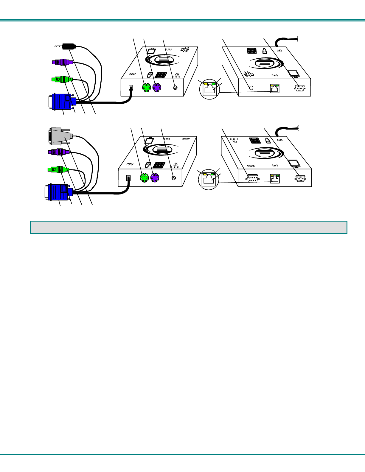
1. Green LED- power indicator- illuminates when power has been supplied to the unit
2. Yellow LED- traffic indicator- illuminates when there is communication between the local and remote units
3. Cat 5- RJ45 female- for connecting the CAT 5 cable
4. Video Connector- 15HD female- for connecting the local user's VGA monitor
5. Audio Jack- 3.5mm stereo audio jack- for connecting to local speakers (models with audio support only)
6. Keyboard Connector- purple female 6 miniDIN- for connecting the local user's keyboard
7. Mouse Connector- green female 6 miniDIN- for connecting the local user's mouse
8. Video Connector- blue 15HD male- for connecting to the video port on the CPU or KVM switch
9. Mouse Connector- green male 6 miniDIN- for connecting to the mouse port on the CPU or KVM switch
10. Keyboard Connector- purple male 6 miniDIN- for connecting to the keyboard port on the CPU or KVM switch
11. Audio Plug- 3.5mm stereo audio plug- for connecting to CPU audio line out (models with audio support only)
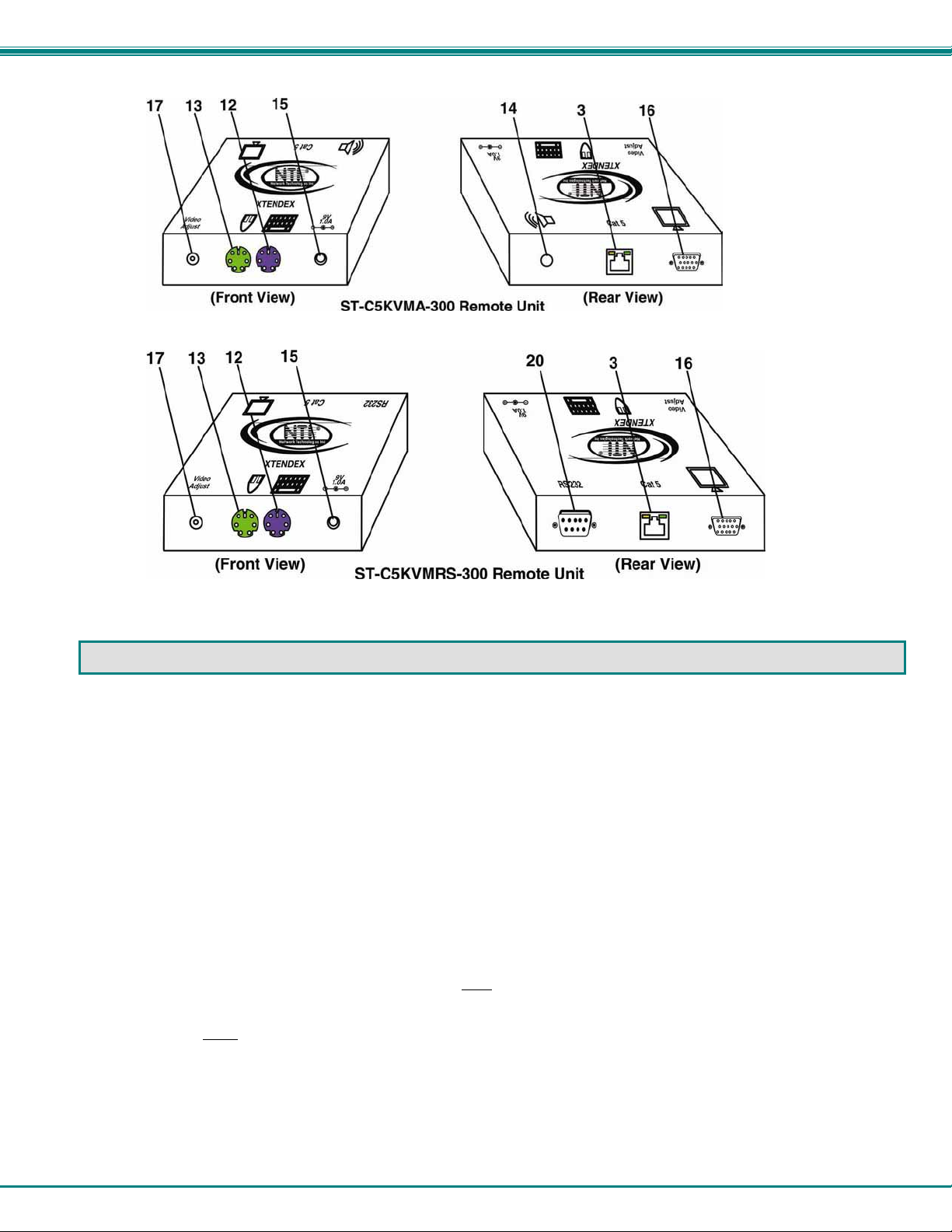
12. Keyboard Connector- purple female 6 miniDIN- for connecting the remote user's keyboard
13. Mouse Connector- green female 6 miniDIN- for connecting the remote user's mouse
14. Audio Jack- 3.5mm stereo audio jack- for connecting to remote speakers (models with audio support only)
15. 9VDC- 1.0A- connection jack for the AC adapter
16. Video Connector- 15HD female- for connecting the remote user's monitor
17. "Video Adjust" screw- for manually adjusting video quality
18. RS232 Connector- 9D male- for connecting the local user's touchscreen monitor (models with RS232 support only)
19. RS232 Connector- light gray 9D female- for connecting to the RS232 port on the CPU or KVM switch
(models with RS232 support only)
20. RS232 Connector- 9D male- for connecting the remote user's touchscreen monitor (models with RS232 support only)
2
Page 6
NTI XTENDEX 300 Foot Extenders
LIMITATIONS
• Hot-plugging of devices is supported provided devices were originally connected at power-up.
• In order for two users to share a PS/2 CPU, the user in control must pause for at least 3 seconds before another user can
take control. After the 3 second pause, either user can take control of the CPU.
For models with audio support:
• The audio input of the XTENDEX with audio support is compatible with the following standard CPU aud io outputs:
• Line out - typically lime green in color
• Speaker out- typically orange in color
• The audio output of the XTENDEX with audio support is compatible with self-powered stereo speakers.
For models with RS232 support:
• The RS232 ports on the Local and Remote Units will support serial devices other than touchscreen monitors as follows:
• 2 simple devices (i.e. mice) connected to each
• 1 complex device (i.e. serial modem, RS232 command port on an NTI switch) connected to
either
• In order for two users to share a PS/2 CPU, the user in control must pause for at least 3 seconds before another user can
take control. After the 3 second pause, either user can take control of the CPU.
• The RS232 port supports all baud rates up to 56K bits per second and the attached CPU must be configured accordingly.
• Headphone out- typically located on the CD-ROM
unit, or
the Remote or Local Unit.
3
Page 7

NTI XTENDEX 300 Foot Extenders
PREPARATION FOR INSTALLATION
• Locations should be chosen for the monitors, mice, and keyboards that also have space to connect the Remote and Local
Units within the distance provided by the cables. If extension cables are needed, contact NTI for the cables required.
• The CAT5 cables must be run to the locations where the Remote and Local Units will be connected. Be careful to route the
cables away from any sources of magnetic fields or electrical interference that might reduce the quality of the video signal
(i.e. AC motors, welding equipment, fluorescent lighting, etc.).
• All cables should be installed in such a way that they do not cause stress on their connections to the equipment. Extended
lengths of cable hanging from a connection may interfere with the quality of that connection. Secure cables as needed to
minimize this.
• Properly shut down and disconnect the power from the CPU and monitors to be separated. If other equipment is involved
whose connections are being interrupted, be sure to refer to the instruction manuals for that equipment for proper
disconnection and re-connection procedures before procee ding.
• Local and Remote Units should be grounded through either a display or source that uses a 3-prong power cord. If only one
unit is grounded, shielded CAT5 cable should be used.
Note: CAT5 connection cable used between NTI XTENDEX Series Local and Remote or any XTENDEX Series products
should not be run underground, outdoors or between buildings.
WARNING: Outdoor or underground runs of CAT5 cable could be dangerous and will void the warranty.
4
Page 8
NTI XTENDEX 300 Foot Extenders
INSTALLATION
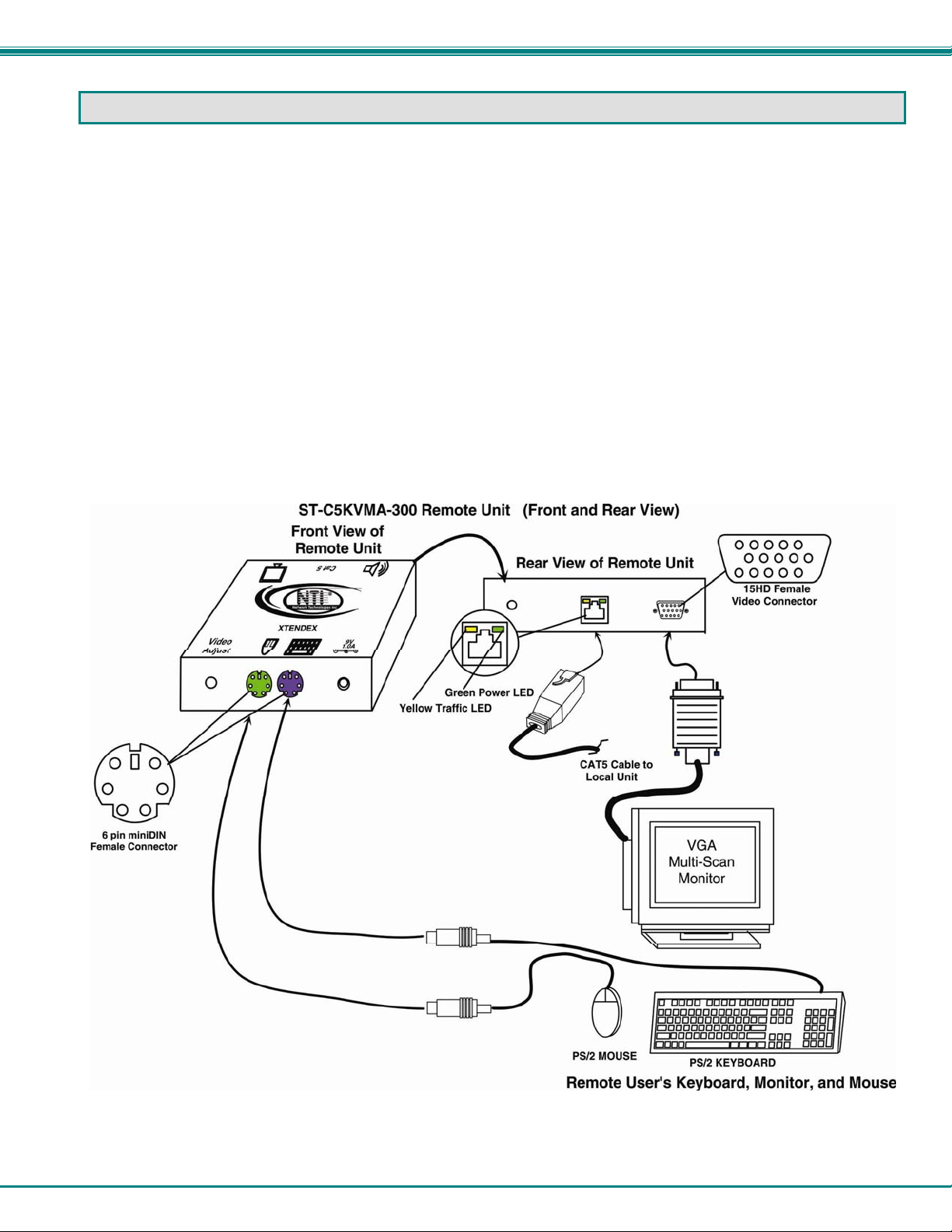
Installing The Remote Unit
1. Position the Remote Unit such that the CAT5 cable, the monitor cable, device cables, and the AC
adapter power connector can each reach the Remote Unit without putting strain on the cables.
2. Connect the monitor cable to the female 15HD video connector on the Remote Unit.
3. Connect the device(s) to the Remote Unit (see Fig. 1)(KVM models only).
a. Connect the keyboard to the purple female 6 pin miniDIN connector on the Remote Unit.
b. Connect the mouse to the green female 6 pin miniDIN connector on the Remote Unit.
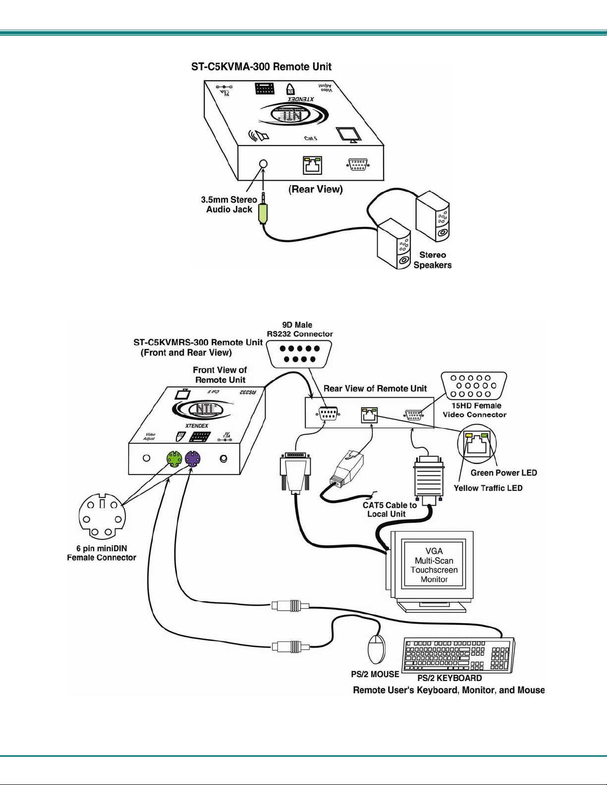
4. If the Remote Unit has audio support, connect the cable from the remote speakers to the 3.5mm
stereo audio jack on the Remote Unit. (See Figure 2)
Figure 1- Connect the Extended Components to the Remote Unit
5
Page 9
NTI XTENDEX 300 Foot Extenders
Figure 2- Connect speakers to the Remote Unit
5. If the Remote Unit has RS232 support, connect the remote user's RS232 cable from a touch
screen monitor to the 9D male port on the Remote Unit.
Figure 3- Connect the extended components to the Remote Unit
6
Page 10
NTI XTENDEX 300 Foot Extenders
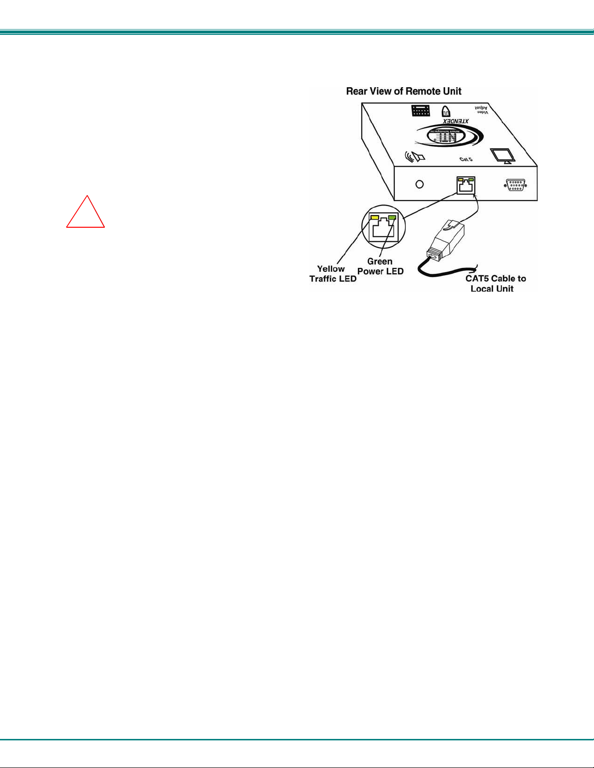
Connect the CAT5 cable
Make sure the CAT5 cable has been installed in
accordance with the “Preparation for Installation”
instructions on page 3. Connect the CAT5 cable to the “Cat 5”
port on the Remote Unit. (See Figure 4.)
When properly inserted the CAT5 cable end should snap
into place.
Note: If an RJ45 wall outlet is being used, connect the
other end of the extension cable to the RJ45 wall outlet.
!
WARNING: Never connect the XTENDEX to an
Ethernet card, Ethernet router, hub or switch or other
Ethernet RJ45 connector of an Ethernet device.
Damage to devices connected to the Ethernet may
result.
Figure 4- Connect the CAT5 cable to the Remote Unit
7
Page 11
NTI XTENDEX 300 Foot Extenders
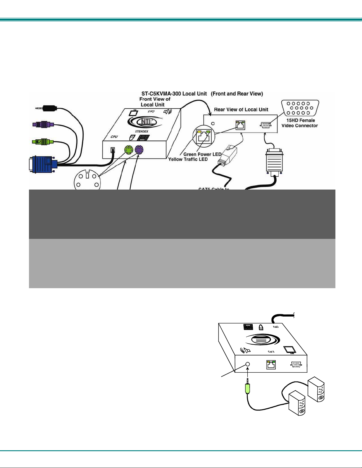
Installing The Local Unit
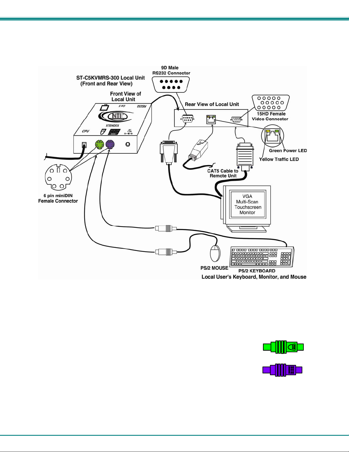
1. Make connections for a local user (see Figure 5).
a) Connect the cable from the local user's VGA monitor to the female 15HD port on the Local Unit.
b) Connect the local user's mouse to the green 6 pin miniDIN female port on the Local Unit.
c) Connect the local user's keyboard to the p urple 6 pin miniDIN female port on the Local Unit.
Figure 5- Connect the local user to the XTENDEX Local Unit
ST-C5KVMA-300 Local Unit
Rear View
R
XTENDEX
Network Tech nologies Inc
NTI
d) If the Local Unit has audio support, connect the
cable from the local speakers to the 3.5mm
stereo audio jack on the Local Unit.
(See Figure 6)
3.5mm Stereo
Audio Jack
Stereo
Speakers
Figure 6- Connect speakers to Local Unit with audio support
8
Page 12
NTI XTENDEX 300 Foot Extenders
e) If the Local Unit has RS232 support, connect the local user's RS232 cable from a touch screen
monitor to the 9D male port on the Local Unit.
Figure 7- Connect the local user with touchscreen monitor to the Local Unit
2. Plug the cables of the Local Unit into the back of the CPU. (See Figure 7.)
a) Connect the blue 15HD cable end to the VGA port on the back of the CPU.
b) Connect the green 6 pin miniDIN cable end with the mouse symbol
on it to the mouse port on the back of the CPU. (KVM models only)
c) Connect the purple 6 pin mini DIN cable end with the keyboard symbol
on it to the keyboard port on the back of the CPU. (KVM models only)
9
(Mouse)
(Keyboard)
Page 13
NTI XTENDEX 300 Foot Extenders
(PURPLE-KEYBOARD)
XTENDEX
AUDIO CONNECTOR
ONE WILL BE MARKED "line
out" ,"spkr", "headphones"
OR WITH THIS SYMBOL
line
out
PS/2 CPU
(GREEN-MOUSE)
ST-C5KVMA-300 Local Unit
(Front View)
(BLUE- VIDEO)
(BLACK- AUDIO)
3.5mm Stereo Plug
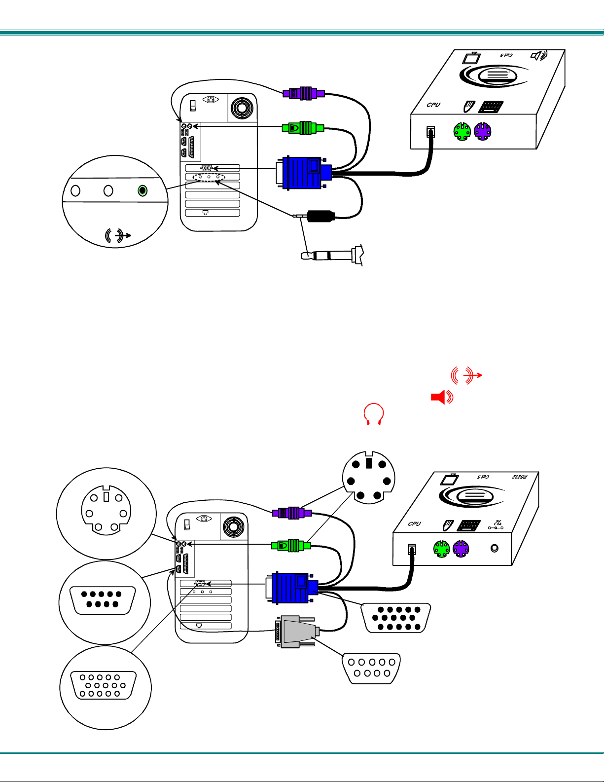
Figure 8- Connect the Local Unit with VGA video and audio support to the CPU
d) If the Local Unit has Audio support, connect the black 3.5mm stereo plug into the "line out",
"spkr", or "headphones" jack on the back of the CPU. (See Figure 8)
Notes:
If all 3 jacks are available, use the jack marked "line out".
The "line out" jack is typically lime green and may be marked with this symbol
The "spkr" jack is typically orange, and may be marked with this symbol
The "headphones" jack may be marked with this symbol
e) If the Local Unit has RS232 support, connect the light gray 9D cable end to the RS232 port on
the back of the CPU. (See Figure 9)
DEVICE
CONNECTORS
6 pin miniDIN
Female Connector
SERIAL
CONNECTOR
(PURPLE-KEYBOARD)
(GREEN-MOUSE)
6 pin miniDIN
Male Connector
NTI
Network Technologies Inc
XTENDEX
ST-C5KVMRS-300 Local Unit
(Front View)
9D Male
RS232 Conne cto r
VIDEO
CONN ECTO R
15HD Female
Video Connector
PS/2 CPU
(BLUE- VIDEO)
(LIGHT GRAY- RS232)
15HD Male
Video Connector
9D Female Connector
Figure 9- Connect the Local Unit with RS232 support to the CPU
NTI
Network Tech nologies Inc
R
- +
R
10
Page 14
NTI XTENDEX 300 Foot Extenders
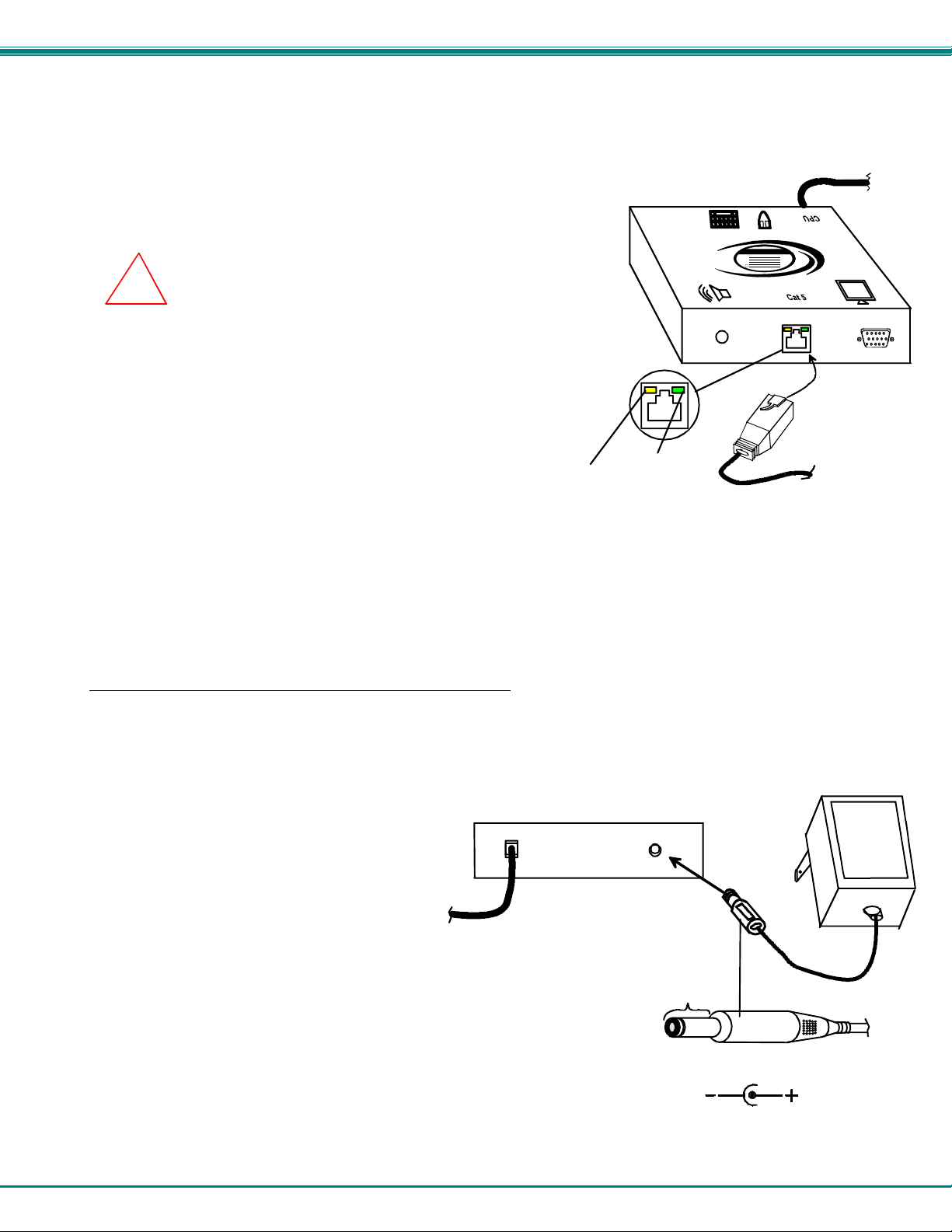
Connect The CAT5 Cable
Connect the CAT5 cable to the “Cat 5” port on the Local Unit. (See Figure 10.) When properly inserted
the cable end should snap into place.
Note: If an RJ45 wall outlet is being used, connect the other
end of the extension cable to the RJ45 wall outlet.
!
WARNING: Never connect the XTENDEX to an Ethernet card,
Ethernet router, hub or switch or other Ethernet RJ45 connector of an
Ethernet device. Damage to devices connected to the Ethernet may result.
Yellow
Traffic LED
Rear View of Local Unit
Green
Power LED
XTENDEX
Network Tech nologies Inc
NTI
R
CAT5 Cable to
Remote Unit
Figure 10- Connect CAT5 cable to Local Unit
Plug-in and Boot Up
For ST-C5V-300,ST-C5VA-300 and ST-C5VRS-300 models
1. Plug the power cord from the monitor into the power outlet.
Connect the AC adapter power connector to the 9VDC ports on the Local Unit. Plug the AC adapter into a power outlet. The
2.
green LED on the RJ45 connector of both the Remote and Local Units should illuminate, indicating that a proper power
connection has been made to them. (See Figure 11.)
3. Turn ON the CPU and Monitor. They should each
react as if they were directly connected to each other.
Note: The yellow LED on each RJ45 connector
will illuminate only on VA models anytime
data traffic is passing between the Local
and Remote Units, indicating proper CAT5
Cable to
CPU
cable connection and communication.
(See Fig. 10)
Front View of ST-C5V-300 Local Uni t
Barrel
(Outside
barrel)
2.1 mm x 5.5 mm Female
Power Connector
9VDC @ 1.0A OUTPUT
(Inside
barrel)
9 VDC
Adapter
ADAPTER
Figure 11- Connect the AC adapter to the Local Unit
11
Page 15
NTI XTENDEX 300 Foot Extenders
For ST-C5KVM-300, ST-C5KVMA-300 and ST-C5KVMRS-300 models
1. Plug the power cord from the monitor into the power outlet.
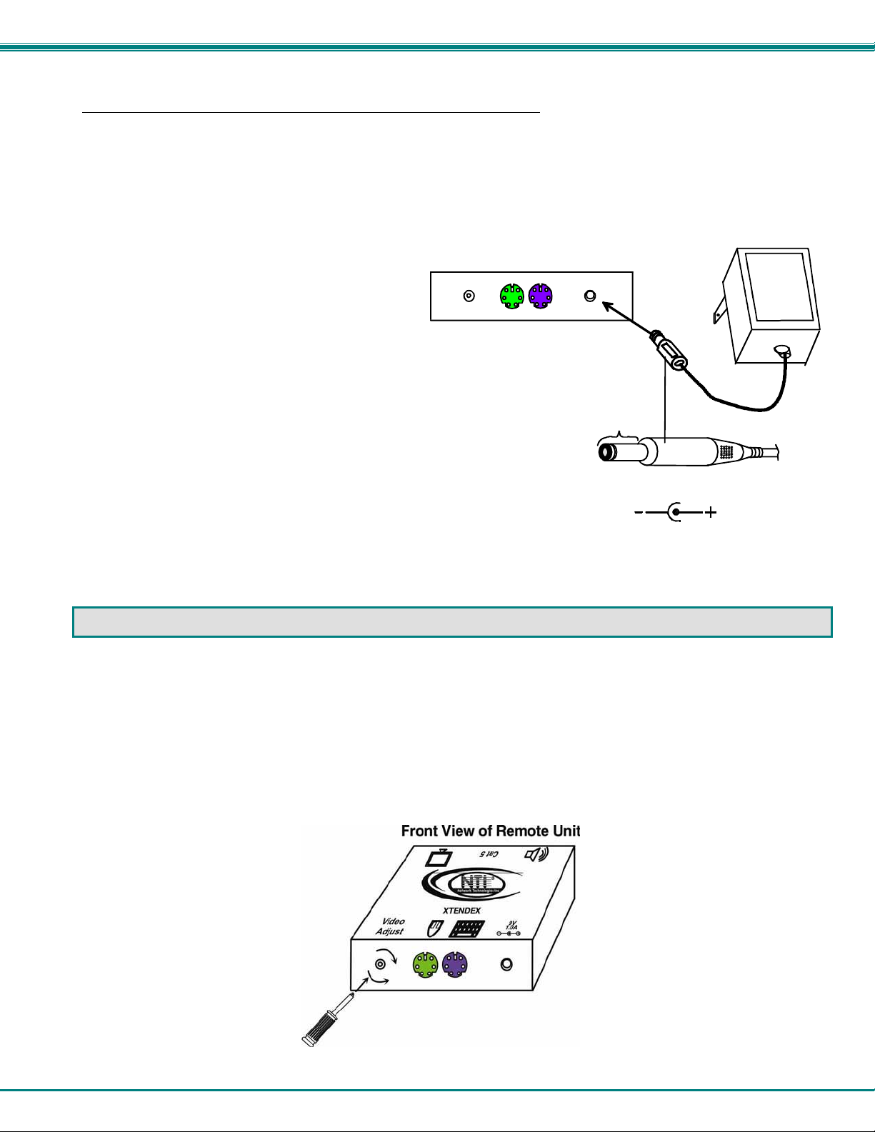
Connect the AC adapter power connectors to the 9VDC ports on the Remote and Local Units. Plug each AC adapter into a
2.
power outlet. The green LED on the RJ45 connector of the Remote and Local Units should illuminate, indicating that a
proper power connection has been made. (See Figure 12.)
3. Turn ON the CPU and Monitor. They should each react as if they were directly connected to each other.
Note: The yellow LED on each RJ45 connector will
Front View of ST- C5 K V M- 300 Remote Unit
illuminate anytime data traffic is passing between
the Local and Remote Units, indicating proper CAT5
cable connection and communication. (See Figure 10)
Barrel
Power Connector
9VDC @ 1.0A OUTPUT
(Outside
barrel)
2.1 mm x 5.5 mm Female
(Inside
barrel)
9 VDC
Adapter
ADAPTER
Figure 12- Connect the AC adapter to the Remote Unit
VIDEO QUALITY ADJUSTMENT
It is possible that on initial startup the image on the monitor will not be as crisp as the image normally is. This is due to the
frequency characteristics of the CAT5 cable. It may be necessary to turn the "Video Adjust" screw on the Remote Unit to
equalize the signal between the Local and Remote Units. Turn the "Video Adjust" screw using a very small screwdriver
(see Figure 13) until the image is crisp and clear. Turn the screw counterclockwise if the image is not crisp and clear enou gh.
Turn the screw clockwise if the image has been over-corrected (such that horizontal lines appear to trai l or shadow at the edge of
an open window). A very small amount of rotation will make a minor change in the image. Ultimately, the image quality should
improve to a satisfactory level.
Note: When the cable is longer than 150 feet some colored lines can be seen at the black-to-white transitions. This is a
normal behavior and is caused by the different twisting rates of each pair of wires in the CAT5 cable.
Figure 13- Turn "Video Adjust" screw for video quality adjustment
12
Page 16
NTI XTENDEX 300 Foot Extenders
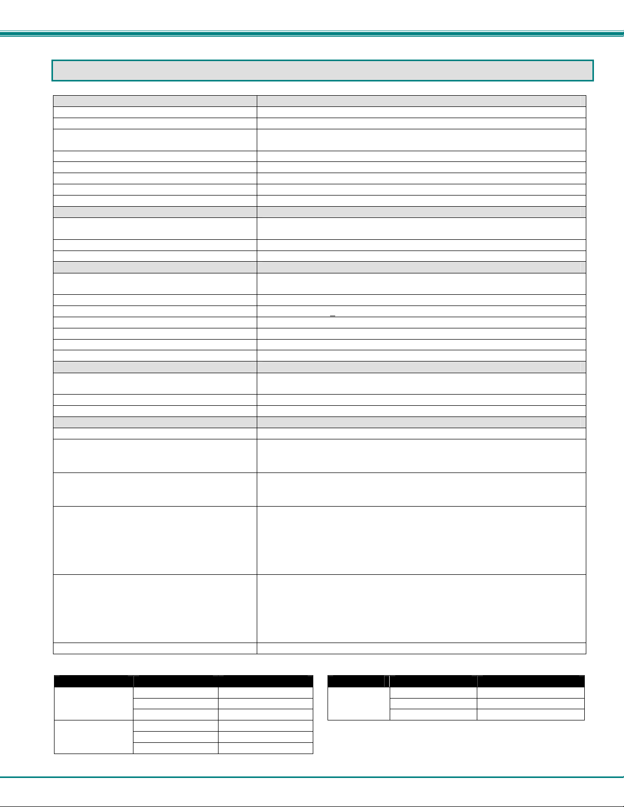
TECHNICAL SPECIFICATIONS
All Models
Video Compatibility XGA, VGA
Video Coupling DC
Video Connectors HD15 male to CPU
Input / Output Impedance 75 Ohms
Input Horizontal Frequency Range 15kHz to 130 Hz
Input Vertical Frequency Range 30 Hz to 150 Hz
Sync Types Supported Separate and composite TTL Level and sync on green
Video Maximum I/O Levels 1.45Vp-p
Models with Keyboard/Mouse support
Keyboard/Mouse Connectors Female 6 pin miniDIN to Keyboard and Mouse
Mouse and Keyboard Compatibility All PS/2 mice and keyboards
Keyboard and Mouse Current Rating 500mA maximum
Models with Audio Support
Audio Connectors 3.5mm stereo jack to speakers
Signal Type Line Level, stereo, unbalanced
Audio Frequency Response 20Hz to 20Khz, + 1dB
Signal-to-noise ratio 76 dBA
Total Harmonic Distortion and Noise 0.017%
Stereo Crosstalk -70 dB
Audio Maximum I/O Levels 3.1Vp-p
Models with RS232 Support
RS232 Connectors 9D male to device
RS232 Baud Rate 56K bps maximum (no adjustment for baud rate is needed)
RS232 Compatibility RXD, TXD, RTS, DTR, CTS, DSR
General
Interconnect Cable CAT5/5e/6 Solid UTP EIA/TIA 568 B wiring w/ male RJ45 connectors
Local Unit Power
ST-C5KVM/ST-C5KVMA/STKVMRS
ST-C5V/ST-C5VA/ST-C5VRS
Remote Unit Power
ST-C5KVM/ST-C5KVMA/ST-5KVMRS
ST-C5V/ST-C5VA/ST-C5VRS
Local Power Consumption (no devices
attached)
Remote Power Consumption (no devices
attached)
Size (In.) WxDxH 3.25x3.4x1
Distances and Resolutions for CAT5/CAT5e, CAT6 and CAT6a Cables
CABLE DISTANCE (feet) RESOLUTION CABLE DISTANCE (feet) RESOLUTION
CAT5/CAT5e
Solid UTP
CAT5/5E Solid
STP
CAT6 Solid UTP
300 1280x1024 at 60Hz 300 1024x768 at 60Hz
150 1600x1200 at 60Hz 150 1280x1024 at 60Hz
100 1920x1200 at 60Hz
300 1024x768 at 60Hz
150 1280x1024 at 60Hz
100 1600x1200 at 60Hz
HD15 female to monitor
Male 6 pin miniDIN to CPU device ports
3.5mm stereo plug to CPU
9D female to CPU
• 120V or 240V at 50 or 60Hz-9VDC/1.0A via AC Adapter
• 120V or 240V at 50 or 60Hz-9VDC/1.0A via AC Adapter
• 120V or 240V at 50 or 60Hz-9VDC/1.0A via AC Adapter
• powered by Local Unit through CAT5 cable
• ST-C5V: 105 mA
• ST-C5VA: 220 mA
• ST-C5VRS: 170mA
• ST-C5KVM: 200 mA
• ST-C5KVMA: 230 mA
• ST-C5KVMRS: 240 mA
• ST-C5V: 105 mA
• ST-C5VA: 220 mA
• ST-C5VRS: 210 mA
• ST-C5KVM: 180 mA
• ST-C5KVMA: 205 mA
• ST-C5KVMRS: 270 mA
CAT6a
Solid UTP
100 1920x1200 at 60Hz
13
Page 17
NTI XTENDEX 300 Foot Extenders
INTERCONNECTION CABLE WIRING METHOD
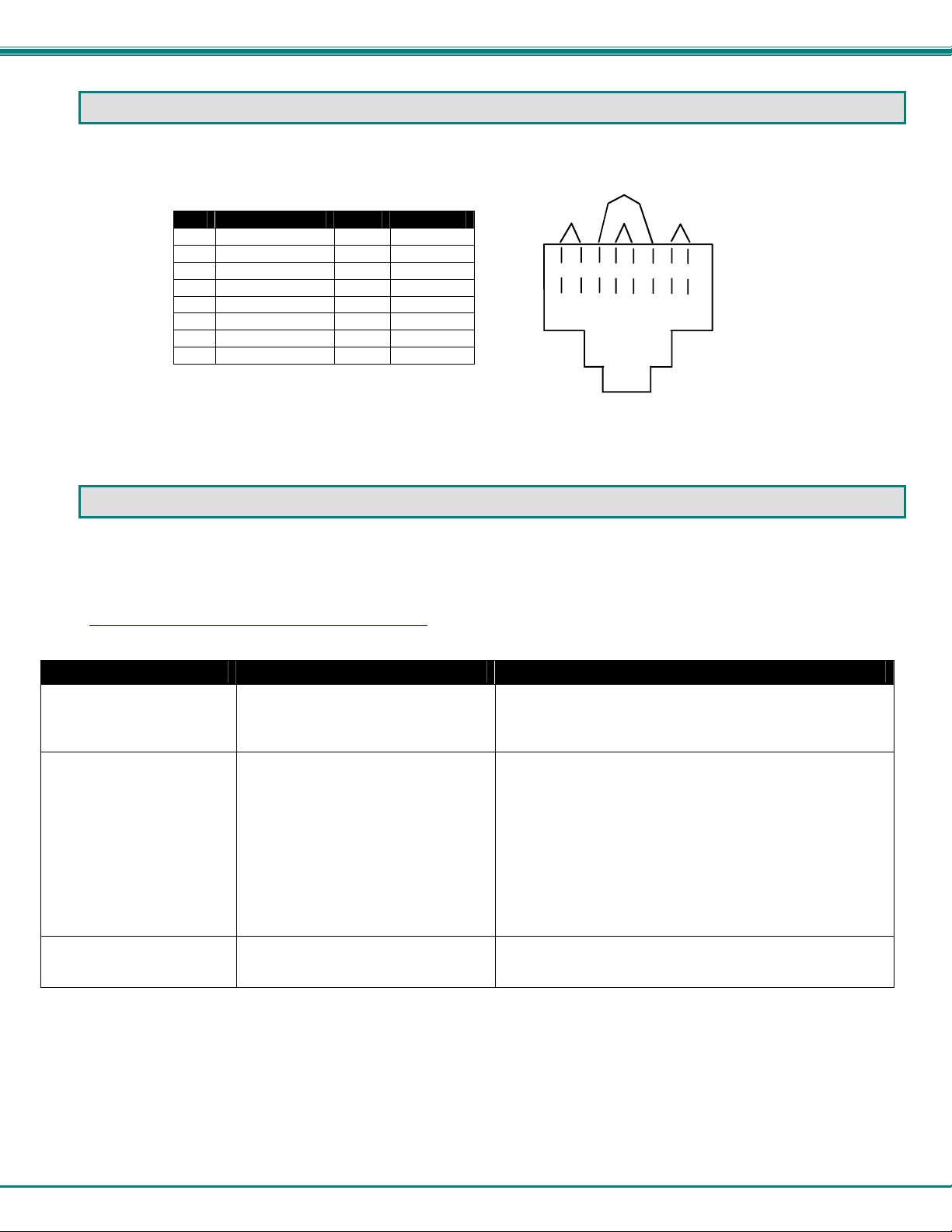
The connection cable between the remote and local is terminated with RJ45 connectors and must be wired according to the
EIA/TIA 568 B industry standard. Wiring is as per the table and drawing below.
1 White/Orange 2 T
2 Orange 2 R
3 White/Green 3 T
4 Blue 1 R
5 White/Blue 1 T
6 Green 3 R
7 White/Brown 4 T
8 Brown 4 R
Pin Wire Color Pair Function
Pair 2 Pair 1
T
1
+
Figure 14- View looking into RJ45 female
Pair 3
Pair 4
T
R
R
T
3
2
4
5
+
-
-
+
R
R
T
8
6
7
+
-
-
TROUBLESHOOTING
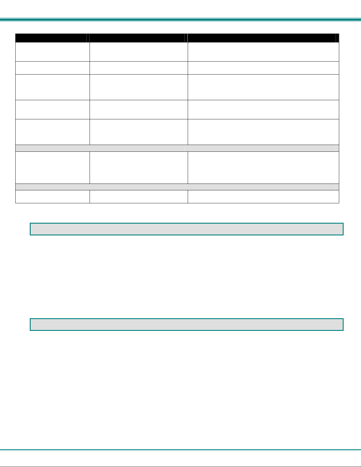
Each and every piece of every product produced by Network Technologies Inc is 100% tested to exacting specifications. W e
make every effort to insure trouble-free installation and operation of our products. If problems are experienced while i nstalling this
product, please look over the troubleshooting chart below to see if perhaps we can answer any questio ns that arise. If the
answer is not found in the chart, a solution may be found in the knowledgebase on our website at
http://information.networktechinc.com/jive/kbindex.jspa
562-7070 and we will be happy to assist in any way we can.
Problem Cause Solution
Remote or Local Unit
green power LED does not
illuminate
No Video on monitor
Video Picture is not sharp
or is smeared
• Power supply is not connected or
plugged-in.
• One or more video cables is loose
or disconnected.
• No power to Remote or Local
Units.
• Video Cable was not attached
when CPU was booted.
• CAT5 cable is not connected.
• Local and/or Remote Unit has no
earth ground
• CAT5 cable is too long.
• Video not adjusted
or please call us directly at (800) 742-8324 (800-RGB-TECH) or (330)
• Make sure outlet is live and AC adapter is plugged-in.
(one for the Remote and one for the Local)
• Make sure 9VDC jack is fully connected
• Check all video cable connections
• Make sure green LEDs are illuminated for local and
remote. If not, see solutions for first problem above.
• With all the cables properly connected, reboot the CPU.
• Check cable connections. Make sure they are snapped-
in properly and completely and reboot.
• Ensure Local and Remote Units are grounded either
through display or a source that uses a 3-prong power
cord.
• Verify length is within specified limits-300'.
• See page 10 for video quality adjustment instruction.
14
Page 18
NTI XTENDEX 300 Foot Extenders
Problem Cause Solution
The picture on the monitor
is black and white, rather
than color
A constant vertical wobble
appears down the screen
Monitor sometimes loses
sync, causing it to go
blank for a second or two
Wrong or missing
characters from those
typed
CPU doesn't detect the
keyboard and the mouse
Models with Audio Support
No audio
Models with RS232 Support
No RS232 communication
The video cable was not attached to
the CPU when it was booted.
CAT5 cable is too close to a strong
power source.
• Electrical power system is very
noisy, particularly the ground.
• The CAT5 cable is not properly
connected.
The keyboard may be in the wrong
mode.
• Keyboard cable or mouse cable
are loose or reversed
• Cat 5 cable is too long
• Audio cable is not properly
plugged in
• Speakers are not plugged in
• CAT5 cable is not properly
connected
• One or more RS232 cables is
loose or disconnected
With the cables all properly connected, reboot the CPU.
Reroute CAT5 cable if possible.
• Make sure the interconnection cable is not near any
power lines.
• Check cable connections. Make sure they are snappedin properly and completely.
• Disconnect keyboard at Remote Unit end and reconnect.
• Reboot the system.
• Check cable connections
• Cat 5 cable can be no more than 300 feet in length
• Check all cable connections
• Verify speakers are connected and powered
• Check CAT5 cable connections
• Check all RS232 cable connections
INDEX
AC adapter, 11
audio support, 5, 8, 10
baud rates, 3
cable(s) needed, 1
CAT5 cable, 7, 11, 13
CAT5 cable pinout, 14
features, 1
green LED, 11
Limitations, 3
RS232 support, 6, 9, 10
serial devices, 3
speakers-self-powered, 3
Technical Specifications, 13
Troubleshooting, 14
Video quality adjustment, 12
yellow LED, 11
WARRANTY INFORMATION
The warranty period on this product (parts and labor) is two (2) years from the date of purchase. Please contact Network
Technologies Inc at (800) 742-8324 (800-RGB-TECH) or (330) 562-7070 or visit our website at http://www.networktechinc.com
for information regarding repairs and/or returns. A return authorization number is required for all repairs/returns.
Manual 074 Rev. 10/23/13
15
 Loading...