

Page 1
T
®
SPLITMUX
Series
SPLITMUX-4K-4RT(-R)
SPLITMUX-USB4K-4RT
Quad Screen 4K Multiviewer
Installation and Operation Manual
S P LITM U X -U S B4 K-4 R
SPLITMUX-4K-4RT
MAN240 Rev Date 5/6/19
Page 2

SPLITMUX Quad Screen 4K Multiviewer
TRADEMARK
SPLITMUX is a registered trademark of Network Technologies Inc in the U.S. and other countries.
COPYRIGHT
Copyright © 2014-2019 by Network Technologies Inc. All rights reserved. No part of this publication ma y be
reproduced, stored in a retrieval system, or transmitted, in any form or by any means, electronic, mechanical,
photocopying, recording, or otherwise, without the prior written consent of Network Technologies Inc, 127 5 Danner
Drive, Aurora, Ohio 44202.
CHANGES
The material in this guide is for information only and is subject to change without notice. Network Technologies Inc
reserves the right to make changes in the product design without reservation and without notification to its users.
FIRMWARE VERSION
1.10
WARRANTY INFORMATION
The warranty period on this product (parts and labor) is two (2) years from the date of purchase. Please contact
Network Technologies Inc at (800) 742-8324 (800-RGB-TECH) or (330) 562-7070 or visit ou r website at
http://www.networktechinc.com for information regarding repairs and/or returns. A return aut horization number is
required for all repairs/returns.
i
Page 3

SPLITMUX Quad Screen 4K Multiviewer
TABLE OF CONTENTS
Introduction......................................................................................................................................................................1
Supported Web Browsers ...............................................................................................................................................2
Materials..........................................................................................................................................................................2
Connectors and LEDs.....................................................................................................................................................3
Mounting..........................................................................................................................................................................4
Single-SPLITMUX mounting........................................................................................................................................5
Dual-SPLITMUX mounting ..........................................................................................................................................6
Reversible Mounting Assembly ................................................................................................................................7
Installation .......................................................................................................................................................................8
Terminal Connection for RS232 ................................................................................................................................10
Ethernet Connection for Remote User Control..........................................................................................................10
Power ON......................................................................................................................................................................11
Control Methods............................................................................................................................................................12
Front Panel Buttons...................................................................................................................................................12
Standard Mode .......................................................................................................................................................12
OSD Mode..............................................................................................................................................................14
Reset Resolution .................................................................................................................................................14
Device Discovery Tool...................................................................................................................................................15
How to Use the Device Discovery Tool.....................................................................................................................15
Use and Operation via Web Interface...........................................................................................................................16
Log In and Enter Password .......................................................................................................................................16
Administration-System............................................................................................................................................18
Administration-Network...........................................................................................................................................20
Administration- Input Settings.................................................................................................................................21
Administration- Output Settings..............................................................................................................................22
Audio Level and Gain..........................................................................................................................................23
Audio Mode Settings ...........................................................................................................................................23
Administration-Mode Settings.................................................................................................................................24
Administration- Custom Settings ............................................................................................................................26
Preset Layouts and Display Preview...................................................................................................................27
Alignment Tools...................................................................................................................................................27
Channel Settings.................................................................................................................................................28
Enable/Disable Channels....................................................................................................................................28
Save/Restore Layouts.........................................................................................................................................29
Cascade Settings....................................................................................................................................................30
Administration-User Config.....................................................................................................................................32
Administration- Firmware........................................................................................................................................33
Administration- System Information........................................................................................................................34
Logout........................................................................................................................................................................34
Support ......................................................................................................................................................................35
Reboot .......................................................................................................................................................................35
Command Line Interface...............................................................................................................................................36
RS232 Control...........................................................................................................................................................36
Baud Rate............................................................................................................................................................36
RS232 Command Protocol.....................................................................................................................................37
Telnet Control............................................................................................................................................................38
Using The Text Menu....................................................................................................................................................39
ii
Page 4

SPLITMUX Quad Screen 4K Multiviewer
Text Menu Navigation..........................................................................................................................................39
Current Mode.............................................................................................................................................................40
System Configuration ................................................................................................................................................41
Network Configuration...............................................................................................................................................43
User Configuration.....................................................................................................................................................45
Input Configuration ....................................................................................................................................................47
Output Configuration..................................................................................................................................................48
Mode Configuration ...................................................................................................................................................50
Load/Save Layout......................................................................................................................................................53
System Information....................................................................................................................................................54
Using OSD.....................................................................................................................................................................55
Navigating the OSD menus....................................................................................................................................55
System Configuration ................................................................................................................................................56
Network Configuration...............................................................................................................................................57
Input Configuration ....................................................................................................................................................59
Output Configuration..................................................................................................................................................60
Mode Configuration ...................................................................................................................................................61
Load / Save Layout....................................................................................................................................................64
System Information....................................................................................................................................................65
Infrared Remote Control................................................................................................................................................66
Materials ....................................................................................................................................................................66
Buttons.......................................................................................................................................................................66
Operation...................................................................................................................................................................67
Changing Ports.......................................................................................................................................................67
Save and Recall......................................................................................................................................................67
Multiple Switch Control...........................................................................................................................................67
Technical Specifications For IRT-UNV......................................................................................................................68
Troubleshooting the IRT-UNV ...................................................................................................................................68
Example of Cascaded Configuration.............................................................................................................................69
Specifications ................................................................................................................................................................72
Troubleshooting.............................................................................................................................................................73
Index..............................................................................................................................................................................73
TABLE OF FIGURES
Figure 1- Attach ear brackets to front corners or rear corners...........................................................................................................4
Figure 2- Attach cable tray (if applicable)...........................................................................................................................................4
Figure 3- Attach rack ears..................................................................................................................................................................5
Figure 4- Assembled unit, ready to mount in rack..............................................................................................................................5
Figure 5- Attach ears and connector plate.........................................................................................................................................6
Figure 6- Attach cable tray connector................................................................................................................................................6
Figure 7- Assembly method for SPLITMUX with cables facing forward.............................................................................................7
Figure 8- Assembled SPLITMUX-4K-4RT-2R....................................................................................................................................7
Figure 9- Video Source/Display Connections-SPLITMUX-4K-4RT....................................................................................................8
Figure 10- Video Source\Display Connections- SPLITMUX-USB4K-4RT..........................................................................................9
Figure 11- RS232 Terminal Connection...........................................................................................................................................10
Figure 12- Ethernet connection........................................................................................................................................................10
Figure 13- Power Switch and LED...................................................................................................................................................11
iii
Page 5

SPLITMUX Quad Screen 4K Multiviewer
Figure 14- Front Panel Button Functions.........................................................................................................................................14
Figure 15- Device Discovery Tool....................................................................................................................................................15
Figure 16- Login prompt to access web interface............................................................................................................................16
Figure 17- Initial page- Administrator...............................................................................................................................................17
Figure 18- Initial page- Non-Admin User..........................................................................................................................................17
Figure 19- System Configuration.....................................................................................................................................................18
Figure 20- Network Configuration....................................................................................................................................................20
Figure 21- Input Settings..................................................................................................................................................................21
Figure 22- Output Settings...............................................................................................................................................................22
Figure 23- Display with sound level indications ...............................................................................................................................23
Figure 24- Mode Settings.................................................................................................................................................................24
Figure 25- PIP Screen Mode Settings .............................................................................................................................................25
Figure 26- Custom Screen Mode Settings.......................................................................................................................................26
Figure 27- Pan and Crop Enabled...................................................................................................................................................27
Figure 28- Cascading SPLITMUXs..................................................................................................................................................30
Figure 29- Cascade Settings ...........................................................................................................................................................30
Figure 30- User Configuration..........................................................................................................................................................32
Figure 31- Firmware Update............................................................................................................................................................33
Figure 32- System Information page................................................................................................................................................34
Figure 33- Text Menu- Login screen................................................................................................................................................39
Figure 34- Text Menu-Main Menu....................................................................................................................................................40
Figure 35- Text Menu-Current Mode Selection ................................................................................................................................40
Figure 36- Text Menu- System Configuration..................................................................................................................................41
Figure 37- Text Menu- Unit Settings................................................................................................................................................41
Figure 38- Text Menu- Serial Port Settings......................................................................................................................................42
Figure 39- Text Menu- OSD Screen Settings ..................................................................................................................................42
Figure 40- Text Menu- Restore Default Settings..............................................................................................................................43
Figure 41- Text Menu- Network Configuration.................................................................................................................................43
Figure 42-Text Menu- IPv4 Network Settings..................................................................................................................................44
Figure 43- Text Menu-Server Settings.............................................................................................................................................45
Figure 44- Text Menu- Users List ....................................................................................................................................................45
Figure 45- Text Menu- Account Settings..........................................................................................................................................46
Figure 46- Text Menu- User Account Settings.................................................................................................................................46
Figure 47- Text Menu- Input Configuration......................................................................................................................................47
Figure 48- Text Menu- Output Configuration ...................................................................................................................................48
Figure 49- Text Menu- Audio Output Configuration.........................................................................................................................49
Figure 50- Text Menu- Mode Settings Menu....................................................................................................................................50
Figure 51- Text Menu- Default Mode Configuration.........................................................................................................................50
Figure 52- Text Menu- Full Screen Mode Settings ..........................................................................................................................51
Figure 53- Text Menu- Quad Mode Settings....................................................................................................................................51
Figure 54- Text Menu- PIP Mode Settings .......................................................................................................................................52
Figure 55- Text Menu- Custom Mode Settings................................................................................................................................53
Figure 56- Text Menu- Load/Save Layout........................................................................................................................................53
Figure 57- Text Menu- System Information......................................................................................................................................54
Figure 58- Front Panel Button OSD Functions ................................................................................................................................55
Figure 59- The OSD Menu...............................................................................................................................................................55
Figure 60- OSD System Configuration.............................................................................................................................................56
Figure 61- OSD Network Configuration ...........................................................................................................................................57
Figure 62- OSD IP Settings .............................................................................................................................................................58
Figure 63- OSD Server Settings......................................................................................................................................................58
Figure 64- OSD Input Configuration ................................................................................................................................................59
Figure 65- OSD Input Settings.........................................................................................................................................................59
Figure 66- OSD Output Settings......................................................................................................................................................60
Figure 67- OSD Mode Settings........................................................................................................................................................61
iv
Page 6

SPLITMUX Quad Screen 4K Multiviewer
Figure 68- Default, Full Screen and Quad Screen Settings.............................................................................................................62
Figure 69- PIP Screen Mode settings.............................................................................................................................................. 63
Figure 70- OSD- Custom Screen Mode Settings.............................................................................................................................64
Figure 71- OSD- Load/Save Layout functions .................................................................................................................................64
Figure 72- Save or Load a Custom Layout......................................................................................................................................65
Figure 73- OSD- System Information Page .....................................................................................................................................65
Figure 74- View of cascaded configuration from Master..................................................................................................................69
Figure 75- View of cascaded configuration from Slave at IP 192.168.3.173 ....................................................................................70
Figure 76- View of cascade configuration from Slave at IP 192.168.3.125......................................................................................70
Figure 77- View of custom configuration of Slave at IP 192.168.3.183............................................................................................71
Figure 78- Current output mode selection........................................................................................................................................71
v
Page 7

SPLITMUX Quad Screen 4K Multiviewer
INTRODUCTION
The SPLITMUX® HD Quad Screen Multiviewer allows you to simultaneously display 4k Ultra High Definition video from four
different computers or video sources on a single monitor providing resolutions up to 4096 x 2160.
Features:
Quad, Picture in Picture, Full Screen, and Custom display modes.
Independent video in to video out resolution.
Supports HDTV input resolutions
o Up to 1080p/36-bit, 2048x1080 @ 60Hz or 1920x1200 @ 60Hz HDMI 1.3a inputs (2.25Gbps ban dwidth).
Supports HDTV output resolutions
o Up to UHD(2160p), 4096x2160 @ 60Hz HDMI 2.0 output (4k/UHD real-time video).
Connect digital video sources to the splitter and display images on a digital monitor.
Output resolution and frame rate independent of input.
Full-screen, quad-screen, picture-in-picture, and custom modes with configurable window transparency.
o Full-screen and quad-screen display at up to 4k resolution
o Picture-in-picture and custom modes display at maximum 1080p resolution
On-screen display.
Front panel pushbutton, two USB hot keyboard/mouse ports (for navigating OSD, moving/resizing windows, naming
inputs, etc.), Ethernet (web server with GUI and Telnet), RS-232, and IR control.
Infinite number of levels of video cascading with web server GUI support .
USB KVM version:
o The two attached USB device ports (for hot keyboard/mouse) double as inputs for human interface device
emulation.
o 2-port USB 2.0 high-speed transparent switch.
HDMI features supported:
o Inputs: 24-, 30-, and 36-bit xvYCC, sRGB, and YCbCr.
o Outputs: 24- and 30-bit sRGB.
o Four-channel mixing stereo with 16-, 20-, or 24-bit uncompressed PCM audio.
o Input Bandwidth up to 165 MHz (2.25 Gbps); Output bandwidth up to 594Mhz (5.94Gbps).
Any DVI source or display can be connected by using the DVI-HD-xx-MM cable (not included).
o Use DVIA-HD-CNVTR-LC or DVI-HD-CNVTR DVI + Audio to HDMI Converters to pass and independently
switch audio signals to the multiviewer.
HDCP compliant - V1.2 (on Inputs) and V1.4\2.2 (on Outputs)
On-screen display
Fluid, real-time video performance with up to 60 frames per second (fps) in all four quadrants
HDMI-embedded audio switching (four-channel stereo, non-mixing or one-channel stereo, mixing).
o Switch audio independently of video from HDMI sources
Control the multiviewer through the front panel buttons, on screen display (OSD), RS232 serial port, infrared remote
control or Ethernet.
1
Page 8
SPLITMUX Quad Screen 4K Multiviewer
Backup and restore multiviewer configuration.
Supported output resolutions can be selected or set to auto detect.
Available options: desktop unit, 1RU rackmount unit, dual side-by-side rackmount units in 1RU.
o Rackmount units can be mounted so that the front panel buttons are facing the front or back of the rack.
o Rackmount units include cable management shelf.
o All units can be purchased with a medical grade power supply for healthcare ind ustries.
SUPPORTED WEB BROWSERS
Most modern web browsers should be supported. The following browsers have been te sted:
Microsoft Internet Explorer 8.0 or higher
Mozilla FireFox 30.0 or higher
Opera 12.02 or higher
Google Chrome 9.0.5 or higher
Safari 5.0 or higher for MAC and PC
MATERIALS
Materials supplied with SPLITMUX-4K-4RT:
NTI SPLITMUX-4K-4RT Multiviewer
1- 120VAC or 240VAC at 50 or 60Hz-5VDC/6A AC Adapter (PS4091)
CT6182 DB9 Female-to-RJ45 Female adapter
CB7094 5 foot CAT5E-SF32-5-BLACK patch cable
CT7003 IR Remote Control with two (2) AAA batteries (PS0154)
Materials supplied with SPLITMUX-USB4K-4RT:
NTI SPLITMUX-USB4K-4RT Multiviewer
1- 120VAC or 240VAC at 50 or 60Hz-9VDC/8A AC Adapter (PS4212)
CT6182 DB9 Female-to-RJ45 Female adapter
CB7094 5 foot CAT5E-SF32-5-BLACK patch cable
CT7003 IR Remote Control with two (2) AAA batteries (PS0154)
Additional Materials Included with SPLITMUX-4K-4RT-R (same as SPLITMUX-4K-4RT plus the following):
2- MP4829 Ear Brackets
2- MP4826 Long Rack Ears
1- MP4825 Cable Tray
12- HW5133 #6-32x1/4” Flat head Screws
Materials Included with SPLITMUX-4K-4RT-2R (same as SPLITMUX-4K-4RT plus the following):
6- MP4829 Ear Brackets
2- MP4827 Short Rack Ears
1- MP4830 Cable Tray Connector
2- MP4828 Connector Plate
2- MP4825 Cable Tray
28- HW5133 #6-32x1/4” Flat head Screws
Additional materials may need to be ordered;
CAT5/5e/6 unshielded twisted-pair cable(s) terminated with RJ45 connectors wired straight thru- pin 1 to pin 1, etc. for Ethernet
connection
Contact your nearest NTI distributor or NTI directly for all of your cable needs at 800-RGB-TECH (800-742-8324) in US & Canada
or 330-562-7070 (Worldwide) or at our website at http://www.networktechinc.com
and we will be happy to be of assistance.
2
Page 9
SPLITMUX Quad Screen 4K Multiviewer
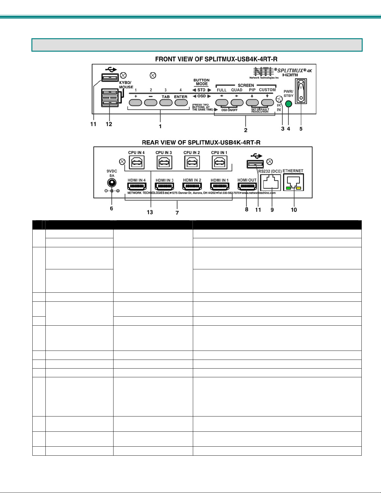
CONNECTORS AND LEDS
#
LABEL CONNECTOR/LED DESCRIPTION
1-4
1
+, -, TAB, ENTER
SCREEN-
2
FULL,QUAD,PIP,MODE
(Display Modes)
Directional Arrows
3 IR IN
4
PWR/STBY
5
6 5VDC
7 HDMI IN 1-4
8 HDMI OUT
9 RS232 (DCE)
10 ETHERNET
11 USB
12 KYBD/MOUSE
13 CPU IN 1-4
Pushbuttons
Pushbuttons
IR Sensor Input sensor to receive IR signals from remote control
Green/Red LED To indicate when the SPLITMUX is powered ON (Green) or in
Rocker switch For switching the SPLITMUX between ON (I) and Standby (O)
Power Jack For connection of power supply
HDMI female connector For connection of HDMI video sources
HDMI female connector For connection of cable to HDMI Monitor
RJ45 female connector For RS232 serial connection of a terminal to control the system
RJ45 female connector For connection to an Ethernet for remote multi-user control
USB Type A Female For connecting USB devices (mouse and keyboard) to control
USB Type A Female For connecting keyboard and mouse to control SPLITMUX from
USB Type B Female For connecting USB device cables from connected PCs
HDMI Input Selection (Standard Mode)
OSD Menu Navigation (OSD Mode)
For selecting the display mode for image placement on the user’s
monitor
Used for OSD Menu Navigation
Also used to toggle the OSD Menu ON/OFF and returning the
SPLITMUX to the default display resolution
Standby (Red)
“9V8A” for SPLITMUX-USB4K-4RT (2.5x5.5mm)
“5V3A” for SPLITMUX-4K-4RT (2.1x5.5mm)
Yellow LED- indicates 100Base-T activity when illuminated,
Green LED – illuminated when Ethernet link is present,
connected CPUs (SPLITMUX-USB4K-4RT only)
OSD menus
10Base-T activity when dark
strobing indicates activity on the Ethernet port
3
Page 10
SPLITMUX Quad Screen 4K Multiviewer
MOUNTING
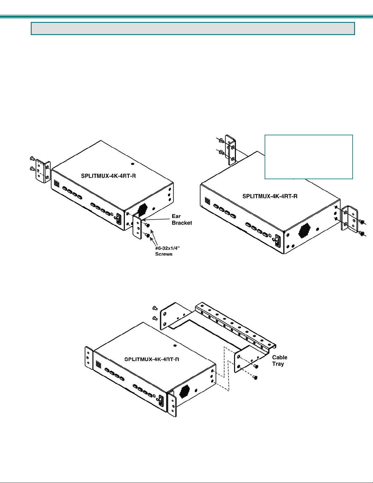
The SPLITMUX-4K-4RT can be purchased in a 1RU case with parts and hardware for mounting i n a ra ck as a single unit
(SPLITMUX-4K-4RT-R) or as a dual unit (SPLITMUX-4K-4RT-2R). (SPLITMUX-4K-4RT is for desktop mount only. The
SPLITMUX-USB4K-4RT comes standard as a rackmount unit.) Follow the instructions below for assembly and installation.
Whether the SPLITMUX will be mounted as a single or a double, brackets will be attached to the case to enable mounting ears or
a connector plate to be attached.
1. Attach the ear brackets to the SPLITMUX. The holes in the brackets should line up with pre-threaded holes in the sides
of the SPLITMUX. Tighten the screws securely.
Note: If the ear brackets are applied to the rear, the cable management tray cannot be used.
FYI: The same hole pattern is
provided at the front and rear of
the SPLITMUX, enabling the
SPLITMUX to be mounted with
the front facing out or rear
facing out.
Figure 1- Attach ear brackets to front corners or rear corners.
2. If the ear brackets have been applied such that the front will face out, assemble the cable tray to the holes in the rear of the
SPLITMUX as shown below.
Figure 2- Attach cable tray (if applicable)
4
Page 11
SPLITMUX Quad Screen 4K Multiviewer
Single-SPLITMUX mounting
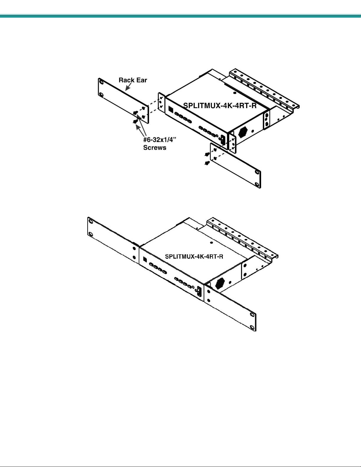
1. To mount a single SPLITMUX in a rack (SPLITMUX-4K-4RT-R), attach the rack mounting ears to the ear brackets using the
#6-32 x 1/4” screws provided. Tighten all screws securely.
Figure 3- Attach rack ears
Figure 4- Assembled unit, ready to mount in rack
2. Install 4 cage nuts (provided) to the rack in locations that line up with the holes in the mounting ears on the SPLITMUX.
3. Secure the SPLITMUX to the rack using the four #10-32x3/4” screws provided. Be sure to tighten all mounting screws
securely.
Note: Do not block power supply vents in the SPLITMUX case. Be sure to enable adequate airflow in front of and
behind the SPLITMUX.
5
Page 12
SPLITMUX Quad Screen 4K Multiviewer
Dual-SPLITMUX mounting
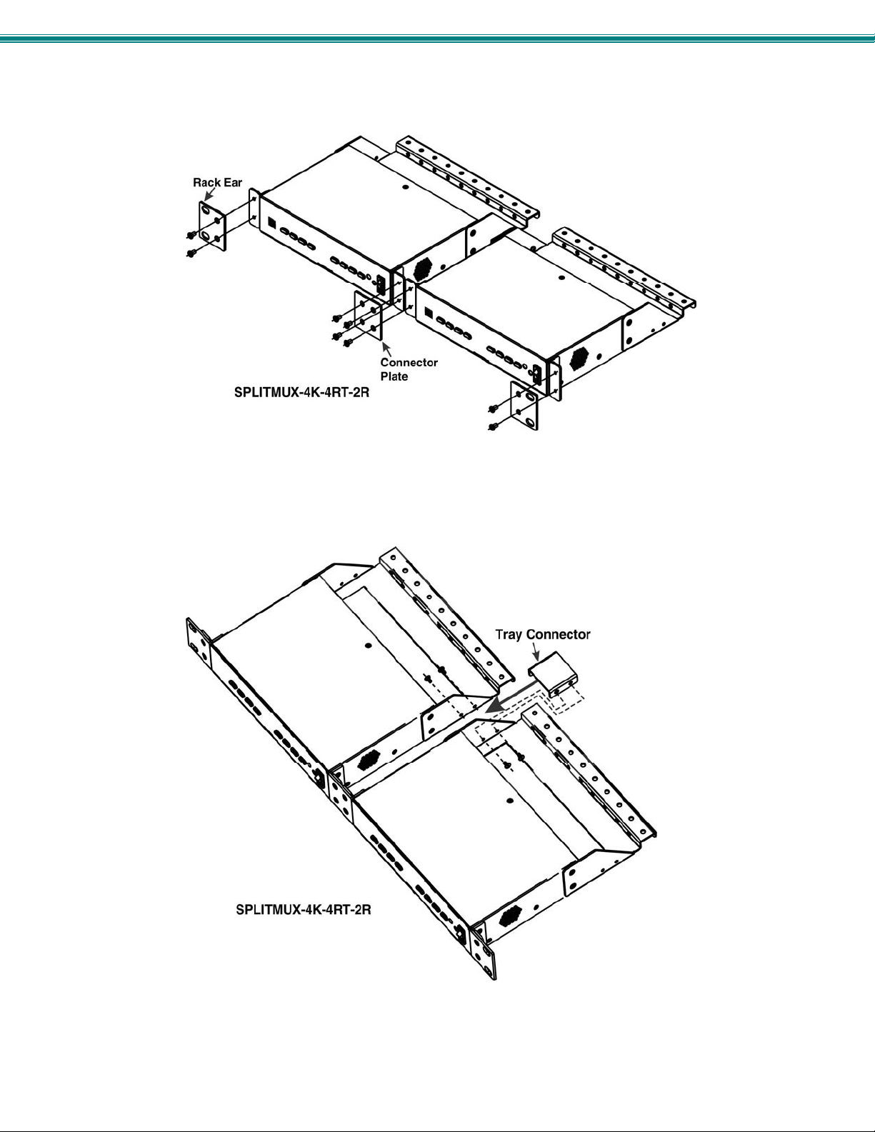
1. To mount a dual SPLITMUX in a rack (SPLITMUX-4K-4RT-2R), attach the rack ears to the far left side of the left SPLITMUX
and right side of the right SPLITMUX using the #6-32 x 1/4” screws provided. Then install a connector plate to join the two
SPLITMUXs in the front.
Figure 5- Attach ears and connector plate
2. Install a cable tray connector between the cable trays using 4 more #6-32x1/4” screws.
Figure 6- Attach cable tray connector
6
Page 13
SPLITMUX Quad Screen 4K Multiviewer
Reversible Mounting Assembly
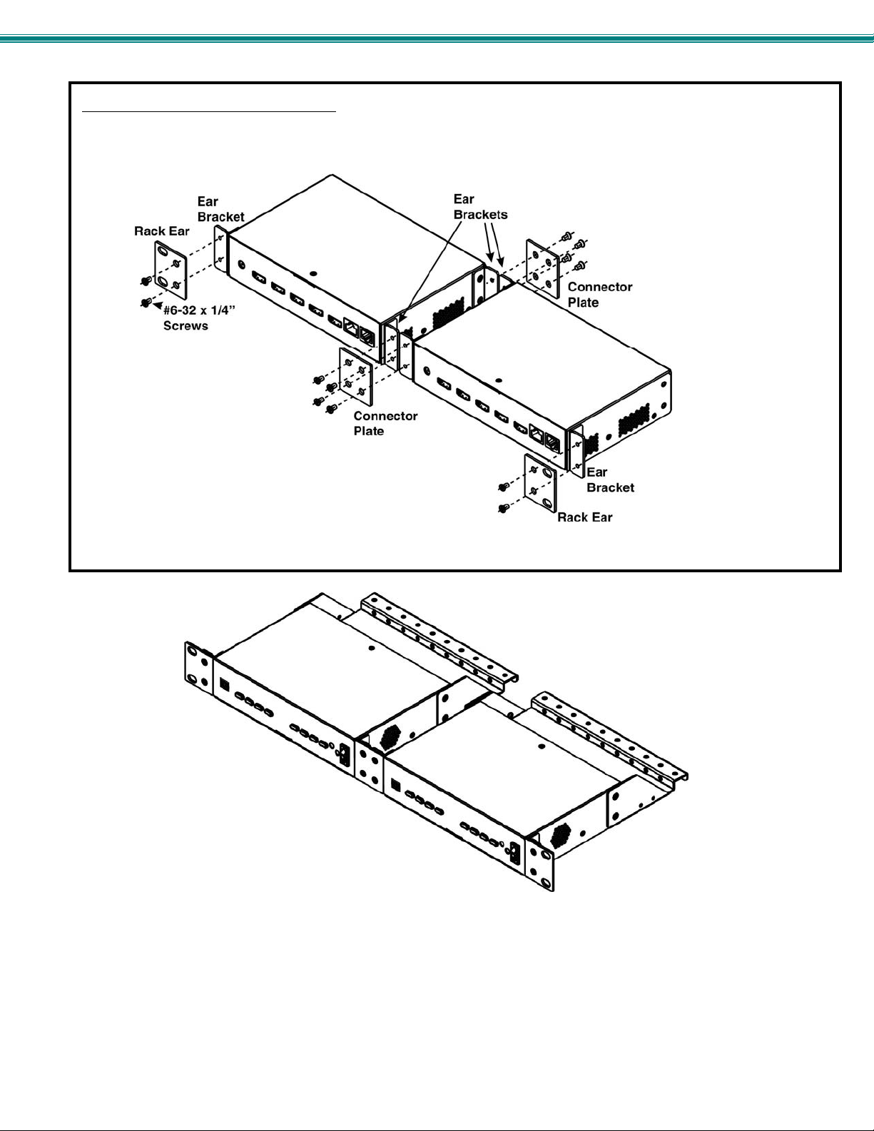
If the SPLITMUXs will have the cable connections facing the front of the rack, then two more ear brackets will need to be installed
to the rear corners of the cases that will be closest to each other. (Install these before attaching the connector plate to the front.)
Once the ear brackets are applied, the ears and connector plates can be attached.
Figure 7- Assembly method for SPLITMUX with cables facing forward
Figure 8- Assembled SPLITMUX-4K-4RT-2R
3. Tighten all screws securely. The SPLITMUX is ready for mounting.
4. Install 4 cage nuts (provided) to the rack in locations that line up with the holes in the mounting ears on the SPLITMUX
assembly.
5. Secure the SPLITMUX to the rack using the four #10-32x3/4” screws provided. Be sure to tighten all mounting screws
securely.
Note: Do not block vents in the SPLITMUX case. Be sure to enable adequate airflow in front of and behind the
SPLITMUX.
7
Page 14
SPLITMUX Quad Screen 4K Multiviewer
INSTALLATION
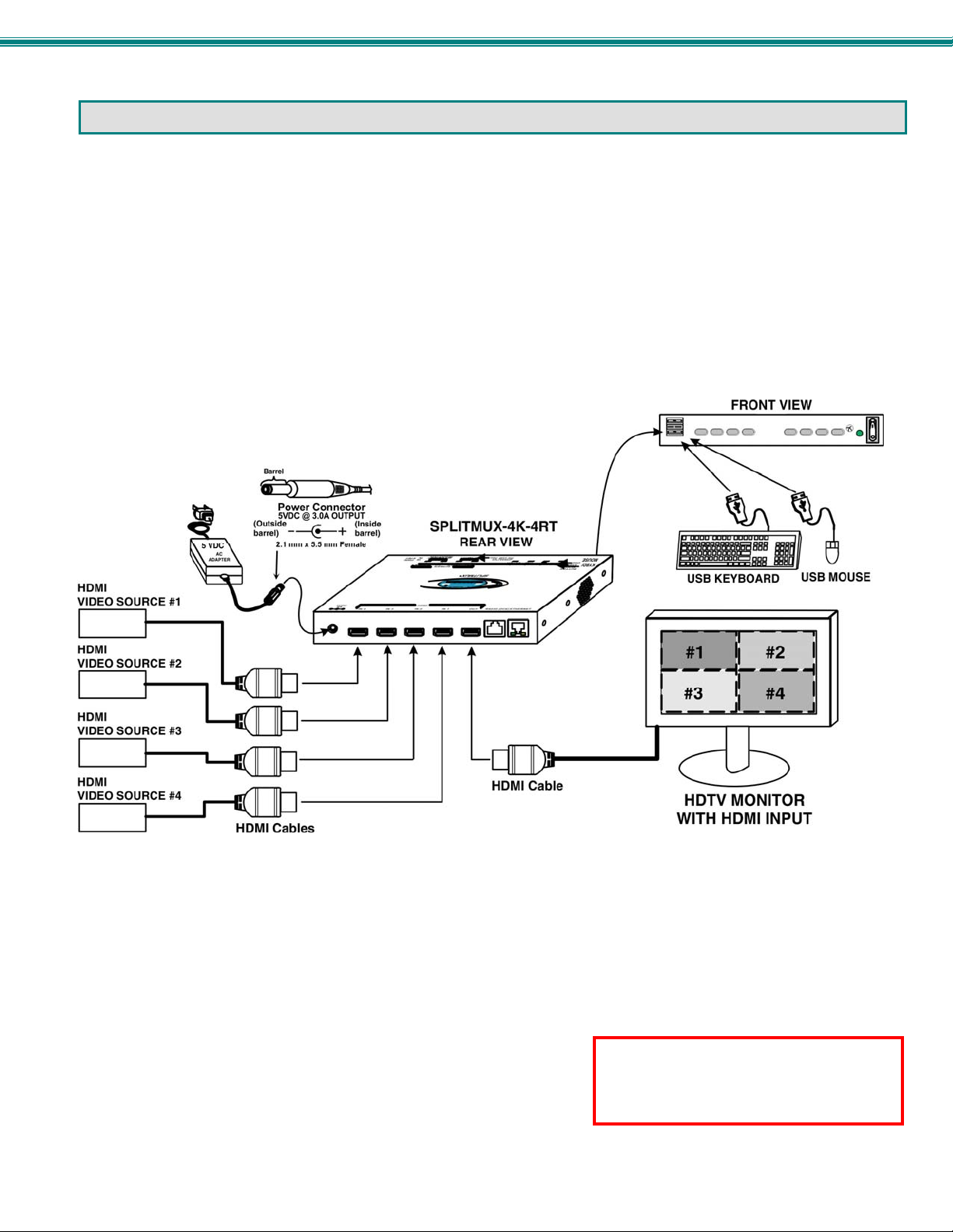
1. Connect each of the HDMI or DVI video sources to the ports on the SPLITMUX marked “HDMI IN x” (x = 1-4).
2. Connect the display to the port marked “HDMI OUT”.
3. Connect the power supply to the power jack and plug it in. In approximately 20 seconds, the LED on the SPLITMUX will
illuminate red (standby).
4. Press the switch on the front to power the SPLITMUX ON. Within 20 more seconds the LED will change from red to green
(ON) and the SPLITMUX will be ready to use.
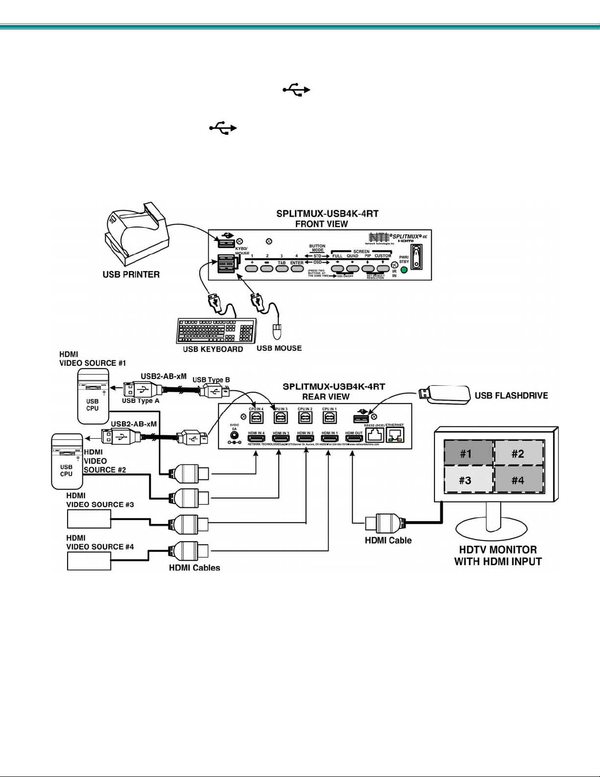
5. For keyboard and/or mouse control of the OSD menu of the SPLITMUX, connect a USB keyboard and/or mouse to the USB
type A ports labeled “KYBD/MOUSE” on the SPLITMUX. On models supporting transparent USB device connection
(SPLITMUX-USB4K-4RT), the keyboard and mouse connected to these ports will also control the keyboard and mouse functi ons
on any connected PC. (See Figure 10)
Figure 9- Video Source/Display Connections-SPLITMUX-4K-4RT
Note: If the connected display does not
support an HDMI input (typically it will
have at least one HDMI input port), the
display will not be compatible.
8
Page 15
SPLITMUX Quad Screen 4K Multiviewer
6. For SPLITMUX units supporting USB CPUs (SPLITMUX-USB4K-4RT), a USB2-AB-xM cable (where x = 0.5 meter, 3,6,10 or
15 feet)(sold separately) can be connected between a USB port on the CPU and a “CPU IN x) port corresponding with the
“HDMI IN x” port the video from the CPU is connected to.
7. Connect any desired USB devices to the ports labeled .
With the connections made in steps 6 and 7, the keyboard and mouse connected to the “KYBD/MOUSE” ports and any USB
device connected to the ports labeled will be active for the connected CPU when the video from that CPU is selected in
the SPLITMUX.
Figure 10- Video Source\Display Connections- SPLITMUX-USB4K-4RT
9
Page 16
SPLITMUX Quad Screen 4K Multiviewer
Terminal Connection for RS232
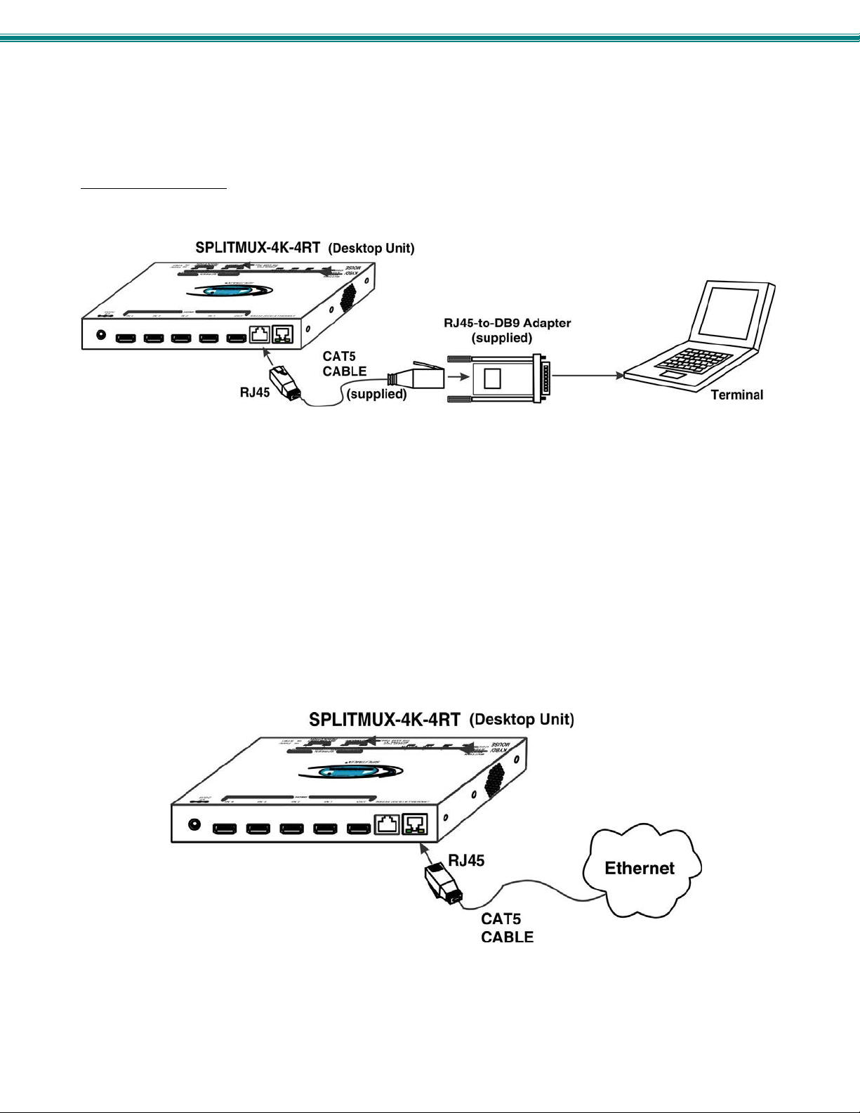
If control via serial connection is going to be used, serial control can be achieved by connecting a control terminal to the “RS232”
port .
To use the “RS232” port
SPLITMUX. Plug the other end of the CAT5 cable into an RJ45-to-DB9F adapter (supplied), and connect the adapter to the
RS232 port on the control terminal.
, connect one end of a CAT5 patch cable (supplied) to the port labeled “RS232” on the rear of the
Figure 11- RS232 Terminal Connection
Ethernet Connection for Remote User Control
To make a remote connection, over the Ethernet, from anywhere on the local area network, connect a CAT5/5e/6 Ethernet
cable with RJ45 male connectors on the ends, wired straight through (pin 1 to pin 1, pin 2 to pin 2, etc.). Up to 8 users can
connect to the SPLITMUX using the Ethernet at a time.
Note: A direct connection from a computer’s Ethernet port to the SPLITMUX “ETHERNET” port may also be made using
the same cable.
Figure 12- Ethernet connection
10
Page 17
SPLITMUX Quad Screen 4K Multiviewer
POWER ON
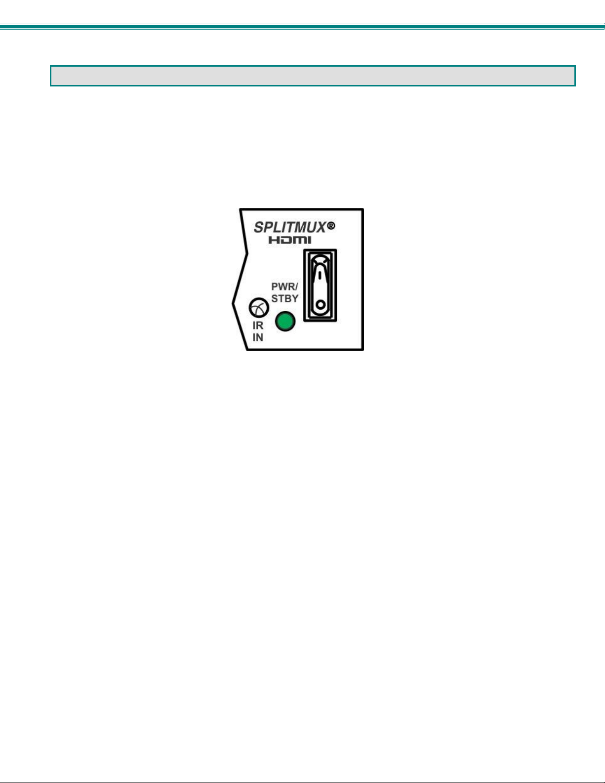
When you plug in the AC adapter between the SPLITMUX and your power supply, with the power switch OFF (switch towards
“O”), the LED on the SPLITMUX will illuminate red after approximately 20 seconds. To use the SPLITMUX, press the power
switch to ON (switch towards “I”). After 20 more seconds the LED will change from red (standby) to green (ON). The
SPLITMUX is now powered up and ready to use.
When powering the SPLITMUX OFF, always press the power switch to OFF (switch towards “O”). Then wait 5 seconds or so
until the green LED changes to red. Once it is red, you can then safely unplug the SPLITMUX from the power source.
WARNING: If you unplug the power source before powering OFF the SPLITMUX at the power switch, you may lose saved
data and configuration information.
Figure 13- Power Switch and LED
11
Page 18
SPLITMUX Quad Screen 4K Multiviewer
CONTROL METHODS
The SPLITMUX can be controlled using any of six methods;
Standard Mode using the front panel buttons
OSD Mode using the front panel buttons and/or keyboard and mouse,
Using the Command Line Interface either through RS232 or remote connection
Using a Text Menu either through RS232 or remote connection
Using a hand-held IR Remote Control
Remotely through the Web Interface using an Ethernet connection.
Front Panel Buttons
The buttons on the front panel have two separate sets of functions, depending upon what mode the SPLITMUX is in; Standard
Mode or OSD Mode.
Standard Mode
In Standard Mode, the left 4 buttons control which video source is viewed as the active image on the monitor, whether the
SPLITMUX is in Full or PiP mode. The right 4 buttons determine which mode format the monitor will display the video signals in.
When FULL is pressed, the input selected using buttons 1 through 4 (or “active” image) will be the only image on
the display. The audio from the selected input will also be heard provided the audio input is set to "Automatic".(See
pages 23 or 60)
When QUAD is pressed, images from all 4 inputs will be displayed equally on the monitor. The audio from the last
active image will continue to be heard.
When PIP is pressed, the active image will occupy the entire screen and the images from the remaining inputs will
be displayed in lower resolution on the right side of the screen.
When CUSTOM is pressed, the images will be displayed in whatever way you have the SPLITMUX configure d to
present them. Each input can be sized and positioned on the screen as desired.
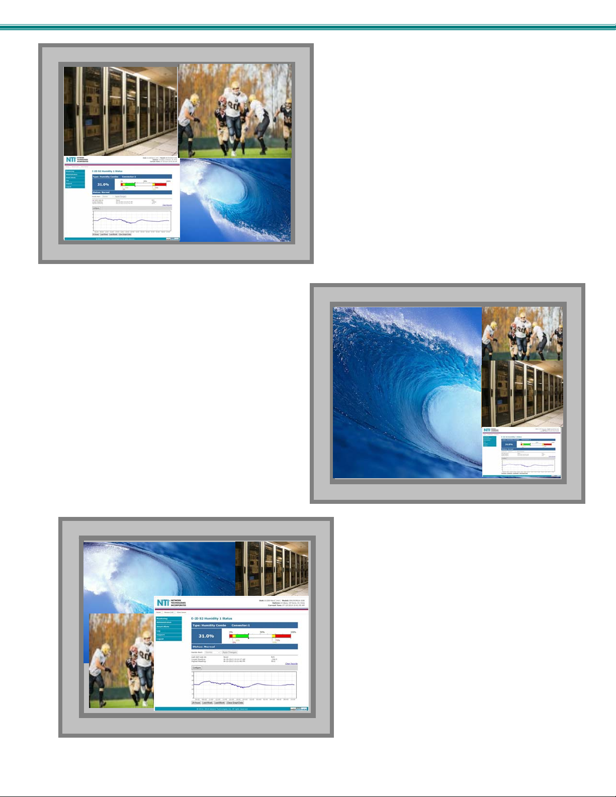
In FULL screen mode, only the active video source will be displayed. The image will be viewed at full size
and up to 4K resolution.
12
Page 19
SPLITMUX Quad Screen 4K Multiviewer
In PIP mode (right) , either 2, 3 or all 4 video sources can be
displayed, with the active source being displayed in its
entirety on the full screen and the remaining selected
images at a reduced resolution for simultaneous viewing.
The position of the reduced images can be configured for
preferred viewing. The maximum output resolution is 1080p
in PIP mode.
In CUSTOM mode (below) the 4 video sources can be
placed where ever you want, at what ever size you want.
The amount of each source that is viewed is determined by
your configuration. The maximum output resolution
is 1080p in Custom mode.
In QUAD screen mode, all four video sources share the screen
equally. Each video source is displayed completely. The
maximum output resolution is 4K in Quad mode.
13
Page 20
SPLITMUX Quad Screen 4K Multiviewer
OSD Mode
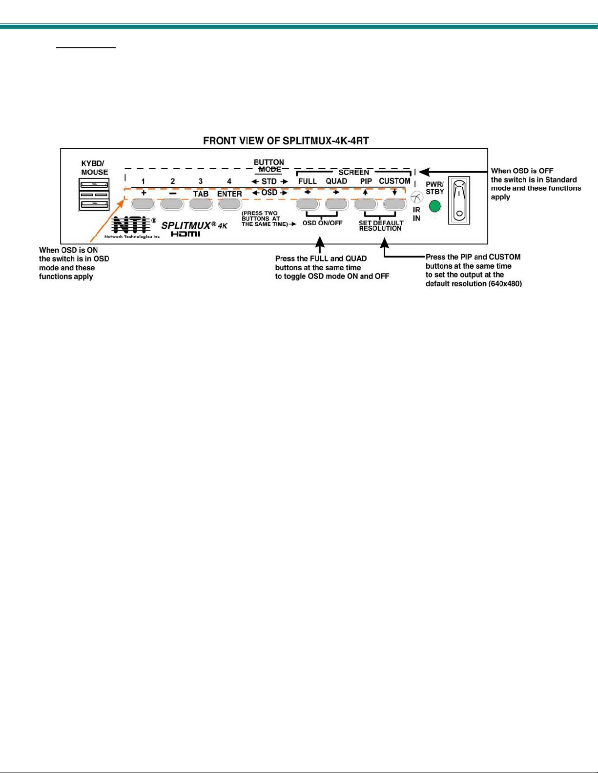
In OSD Mode, the buttons are used to navigate and control the SPLITMUX using the OSD menu.
To bring up the OSD menu, press the FULL and QUAD buttons at the same.
To exit the OSD menu, press the FULL and QUAD buttons at the same time again, or press <Esc> on the keyboard..
Figure 14- Front Panel Button Functions
Reset Resolution
In the event an incompatible resolution setting is applied to the SPLITMUX, to quickly restore the images of video sources to the
SPLITMUX, press the PIP and CUSTOM buttons at the same time. This will reset the output to the default resolution of
640x480 @60Hz.
14
Page 21
SPLITMUX Quad Screen 4K Multiviewer
DEVICE DISCOVERY TOOL
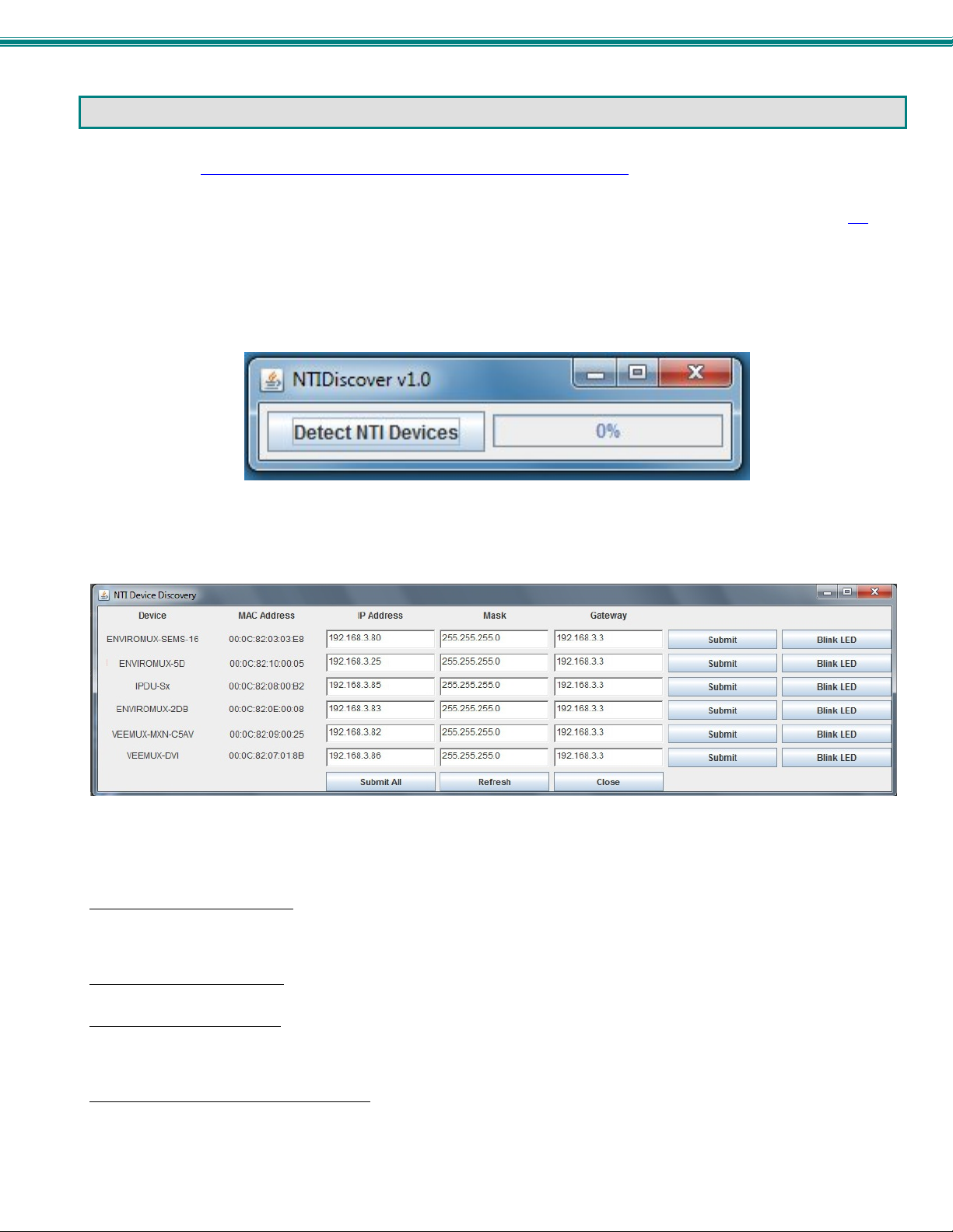
In order to easily locate NTI Devices on a network, the NTI Device Discovery Tool may be used. The Discover Tool can be
downloaded from http://www.networktechinc.com/download/d-4k-hdmi-multiviewer.html, unzipped and saved to a location on your
PC. To open it just double-click on the file NTIdiscover.jar . This will open the NTI Device Discovery Tool.
Note: The Device Discovery Tool requires the Java Runtime Environment (version 6 or later) to operate. Here is a link to
the web page from which it can be downloaded.
Note: The computer using the Device Discovery Tool and the NTI Device must be connected to the same subnet in order
for the Device Discovery Tool to work. If no devices are found, the message “No Devices Found” will be displayed.
Tip: If your Windows program asks which program to open the NTIDiscover.jar file with, select the Java program.
Figure 15- Device Discovery Tool
Click on the “Detect NTI Devices” button to start the discovery process. After a short time, the tool will display all NTI devices on
your network, along with their network settings.
How to Use the Device Discovery Tool
To Change a Device’s Settings
on the Enter key, or the Submit button on that row. If the tool discovers more than one device, the settings for all devices can be
changed and you can click on the Submit All button to submit all changes at once.
To Refresh the list of devices
To Blink the LEDs of the unit
button will change to a “Blinking….” button. The LEDs of the unit will blink until the Blinking… button is clicked on, or the NTI
Device Discovery Application is closed. The LEDs will automatically cease blinking after 2 hours.
To Stop the LEDs of the unit from blinking
button.
, within the row of the device whose settings you wish to change, type in a new setting and click
, click on the Refresh button.
, click on the Blink LED button (This feature is not supported on all products.) The Blink LED
, click on the Blinking… button. The Blinking…. button will change to a Blink LED
15
Page 22
SPLITMUX Quad Screen 4K Multiviewer
USE AND OPERATION VIA WEB INTERFACE
A user may configure the settings of the SPLITMUX using the Web Interface via any web browser (see page 2 for supported web
browsers). To access the Web Interface, connect the SPLITMUX to the Ethernet (page 10). Use the Device Discovery Tool
(page 15) to setup the network settings. Then, to access the web interface controls, the user must log in.
Note: In order to view all of the graphics in the Web Interface, the browser’s JavaScript and Java must be enabled.
By default, the SPLITMUX is configured to dynamically assign network settings received from a DHCP server on the network it is
connected to. (This can be changed to a static IP address to manually enter these settings in the Network Settings on page 20.)
The SPLITMUX will search for a DHCP server to automatically assign its IP address each time the unit is powered up. If the
SPLITMUX does not find a DHCP server, the address entered into the static IP address field (page 20-default address shown
below) will be used. If a DHCP server on the network has assigned the IP address, use the Device Discovery Tool to identify the
IP address to enter when logging in to the SPLITMUX, or use the OSD menu to view the System Info page.
Note: The computer using the Device Discovery Tool and the NTI Device must be connected to the same subnet in order
for the Device Discovery Tool to work. If no devices are found, the message “No Devices Found” will be displayed.
Log In and Enter Password
To access the web interface, type the current IP address into the address bar of the web browser. (The default IP address for the
SPLITMUX is shown below):
To open a SSL-encrypted connection, type:
Address
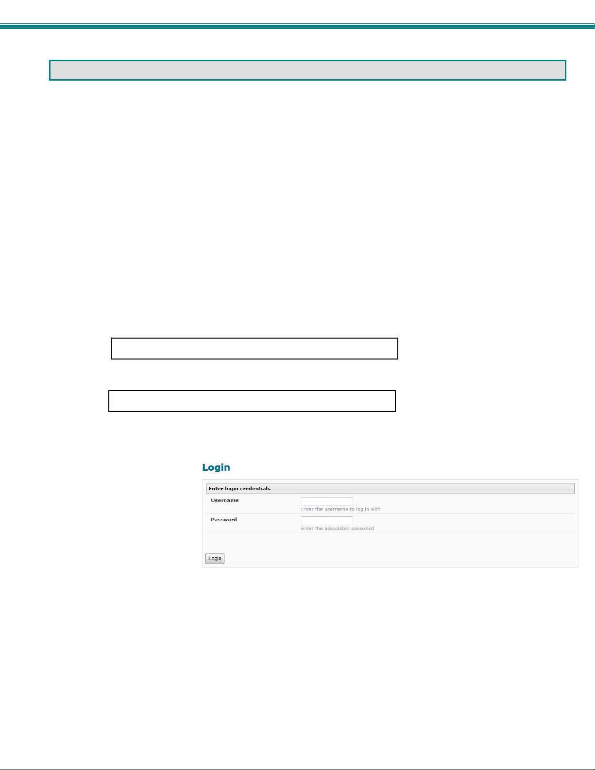
A log in prompt requiring a username and password will appear:
Username = root
http://192.168.1.30
https://192.168.1.30
Password = nti
(lower case letters only)
Note: usernames and passwords
are case sensitive
Figure 16- Login prompt to access web interface
16
Page 23
SPLITMUX Quad Screen 4K Multiviewer
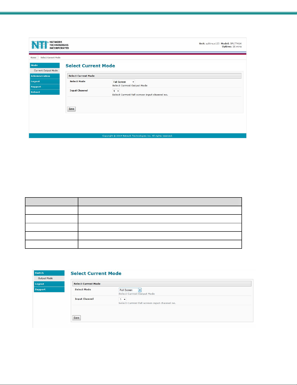
With a successful log in, a screen similar to the following will appear:
Figure 17- Initial page- Administrator
The initial page is the Mode page where the current operating mode of the SPLITMUX is selected and the input channel to be
displayed in Full Screen mode is assigned. A menu to the left is presented to administrative users with access to all pages used
to manage the functions of the SPLITMUX. When the selected mode is Quad, PIP or Custom the Input Channel selected
indicates which input will pass audio through to the output (provided the audio mode for each inp ut is set to Automatic (page 23).
Function Description
MODE Select the current operating mode and main input channel
ADMINISTRATION Configure all network and multi-user access settings (page 18)
LOGOUT Log the user out of the SPLITMUX web interface
SUPPORT Links for downloading a manual or firmware upgrades
REBOOT Enables user to reboot the SPLITMUX using the web interface
A non-administrative user will only have access to select the current mode or to the support links.
Figure 18- Initial page- Non-Admin User
17
Page 24
SPLITMUX Quad Screen 4K Multiviewer
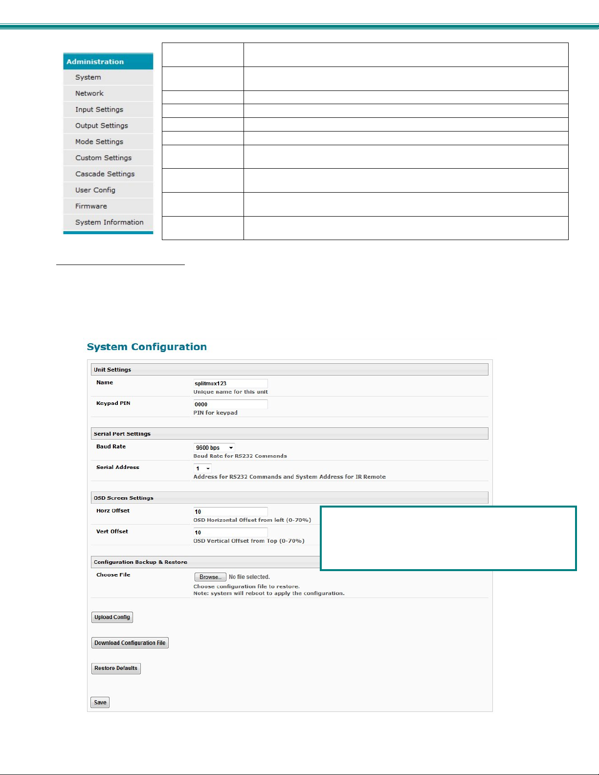
System Fields for applying unit settings (name and keypad PIN), Serial configuration
settings, OSD screen position, and configuration backup and restore options
Network Fields for providing all the network settings the SPLITMUX and access control
settings
Input Settings Display configuration settings for each input channel
Output Settings Video and Audio controls for the output channel
Mode Settings All settings for each operating mode of the SPLITMUX
Custom Settings Settings for customizing the layout of the channels on the display
Cascade Settings Settings to control cascading of the video and audio inputs/outputs on other
SPLITMUXs to/from this SPLITMUX
User Config Fields for assigning users, access privileges, passwords, contact settings, and
schedule settings
Firmware For updating the firmware of the SPLITMUX when improved software becomes
available.
System
Information
Provides firmware version, MAC address, network settings and input
connection status
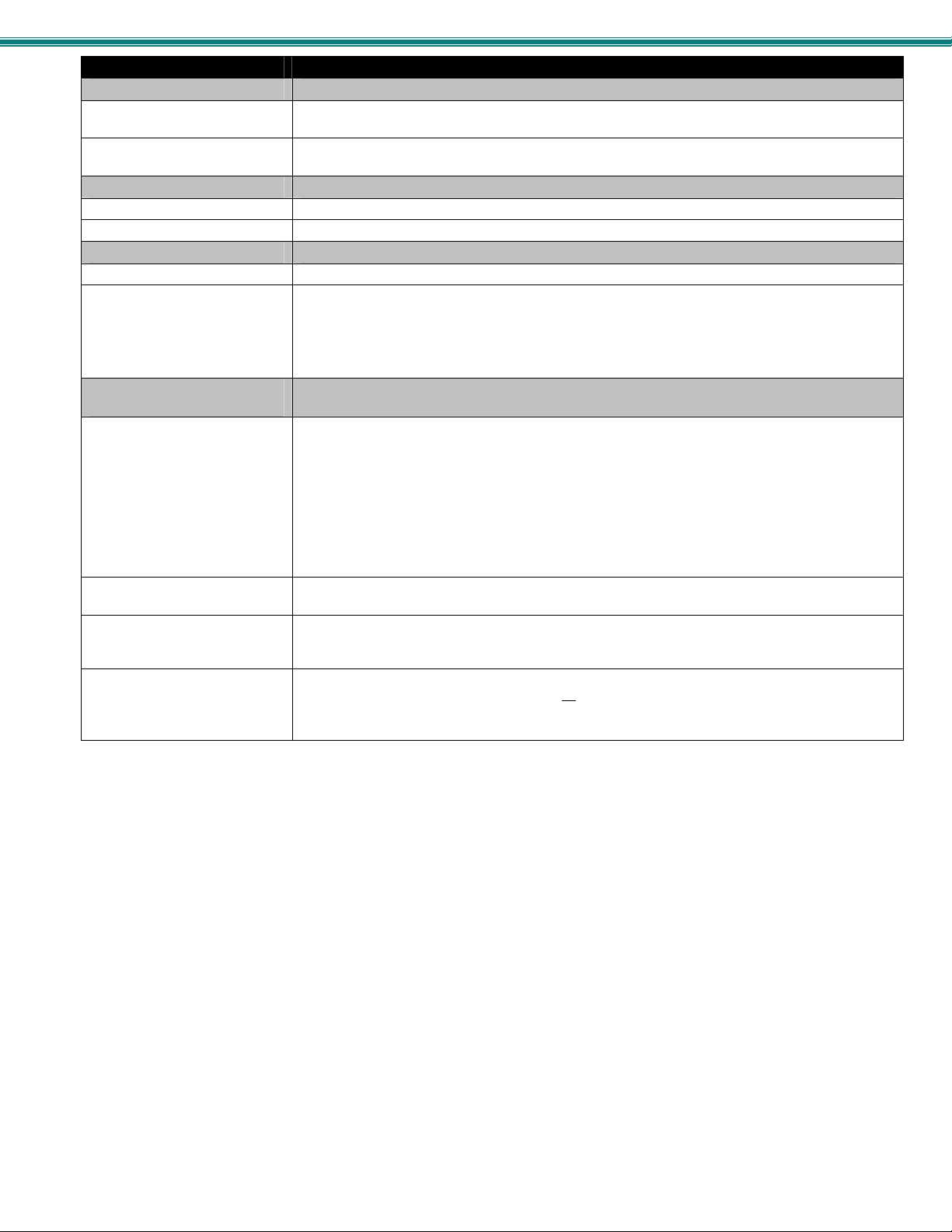
Administration-System
The System Configuration page provides blocks to enter the switch name and a PIN number that will be used to allow access to
the SPLITMUX from the front panel. The name will appear on each page in the web interface identifying which SPLITMUX is
being controlled. Serial port settings for communication with the unit can be entered and the position of the OSD menu on the
monitor is defined. Configuration Backup and Restore provides utility for saving all configuration settings to a file on your PC and
being able to restore them at any time, in addition to being able to restore the SPLITMUX to default settings with the click of a
button.
Note: Changing the OSD Screen Settings will only be
effective when the output resolution is set to 1080P or
less. When set above 1080P, the default settings of 10
will take effect, regardless of what these values are
changed to.
Figure 19- System Configuration
18
Page 25
SPLITMUX Quad Screen 4K Multiviewer
System Settings Description
Unit Settings
Name Unique name for this SPLITMUX to appear on the login page and header of each web interface
Keypad Pin PIN number that must be entered before using the keypad to change settings- 4 digits using
Serial Port Settings
Baud Rate Baud rate for RS232 commands- select a value between 1200 and 115200 bps
Serial Address Serial Address for RS232 commands and for the IR Remote- select value from 1-15
OSD Screen Settings
Horiz Offset OSD Horizontal Offset from left (0-70%)
Vert Offset OSD Horizontal Offset from top (0-70%)
Configuration Backup and
Restore
Choose file Browse for a saved configuration file to be restored to the SPLITMUX. Upon selection, press
page
buttons 1-4.
Note: Changing the OSD Screen Settings will only be effective when the output
resolution is set to 1080P or less. When set above 1080P, the default Horiz. Offset and
Vert. Offset settings of 10 will take effect, regardless of what these values are changed
to.
“Save” and the SPLITMUX will restore the configuration settings and reboot. Allow 1 minute
before trying to reconnect and log in again.
Note: The IP address will be set to the IP address in the file and may be different
Note: Before overwriting the existing configuration, consider whether the existing
configuration should be saved first. If it will be saved, be sure to save the current
configuration file under a different name than the configuration file to be loaded.
Upload Config
Download Configuration File Click this button to save the configuration of the SPLITMUX to a location on your PC. This file
Restore Defaults Click this button to restore the SPLITMUX to the configuration settings it had upon receipt from
Click on the Browse button to browse to the file, then click on “Upload Config”, and restore the
SPLITMUX to the configuration stored in the uploaded file.
can be restored using the “Upload Config” button in the event you wish to return the SPLITMUX
to a former state
the factory. Be careful! This will erase all
SPLITMUX will reboot. Allow 1 minute before trying to reconnect and log in again.
Confirmation is required.
user configuration settings. Upon restoration, the
19
Page 26
SPLITMUX Quad Screen 4K Multiviewer
g
y
Administration-Network
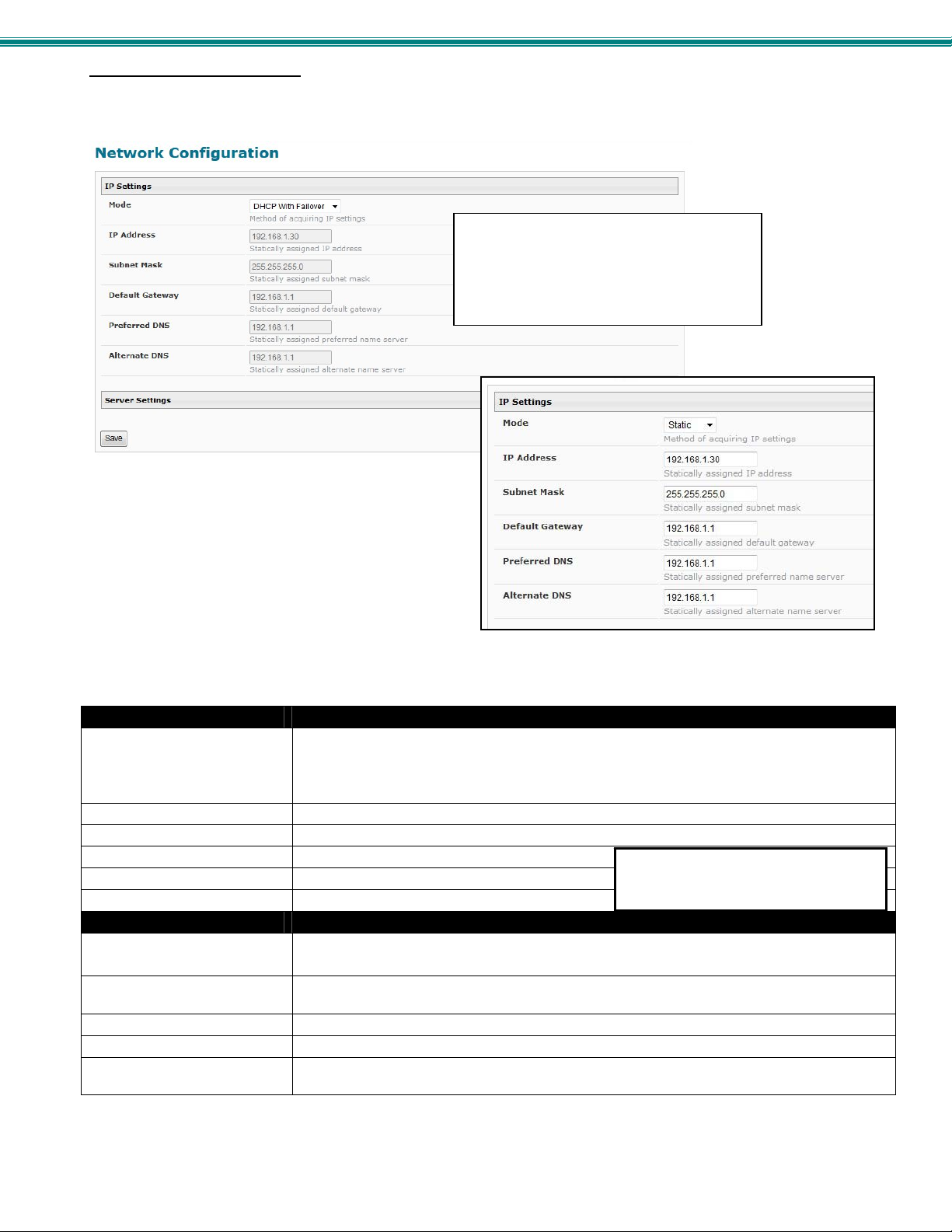
The Network Configuration page is where all network settings are entered. These settings determine how you will remotely
access the SPLITMUX.
Note: When Mode is set to “DHCP With Failover”, in the
event the DHCP server is not available, the SPLITMUX
will automatically revert to the Static IP address and
settings assigned.
This IP address is ONLY used if the Mode
is set to “Static” ” (settings are grayed-out
when set to DHCP). The System
Information page always shows the
assigned IP address whether the Mode is
set to “Static” or “DHCP”. (See pa
e 32)
Figure 20- Network Configuration
IP Settings Description
Mode Select the method for acquiring IP Settings- Static (manual), DHCP with Failover (automatic)
or Disable. Failover enables the SPLITMUX to automatically switch to the Static Mode IP
settings in the event the DHCP server is not available.
(default is DHCP With Failover)
IP Address Enter valid IPv4 address (for Static Mode) (default is 192.168.1.30)
Subnet Mask Enter valid subnet mask (for Static Mode)
Default Gateway Enter valid default gateway (for Static Mode)
Primary DNS Address Enter preferred name server (for Static Mode)
Alternate DNS Address Enter alternate name server (for Static Mode)
Server Settings Description
Enable Telnet Place a checkmark in the box to enable access to the SPLITMUX via Telnet
The default is disabled.
Allow HTTP access Place a checkmark in the box to enable access to the SPLITMUX via standard (non-secure)
HTTP requests (default is enabled)
HTTP Port Port to be used for standard HTTP requests
HTTPS Port Port to be used for HTTPS requests
Web Timeout Number of minutes after which idle web users will be logged-out (maximum is 32000, enter 0
to disable this feature)
Note: If you select “DHCP” for the mode, make sure a DHCP server is running on the network the SPLITMUX is
connected to.
When in DHCP mode, the Primary
and Alternate DNS addresses are set
b
the DHCP server.
20
Page 27
SPLITMUX Quad Screen 4K Multiviewer
Administration- Input Settings
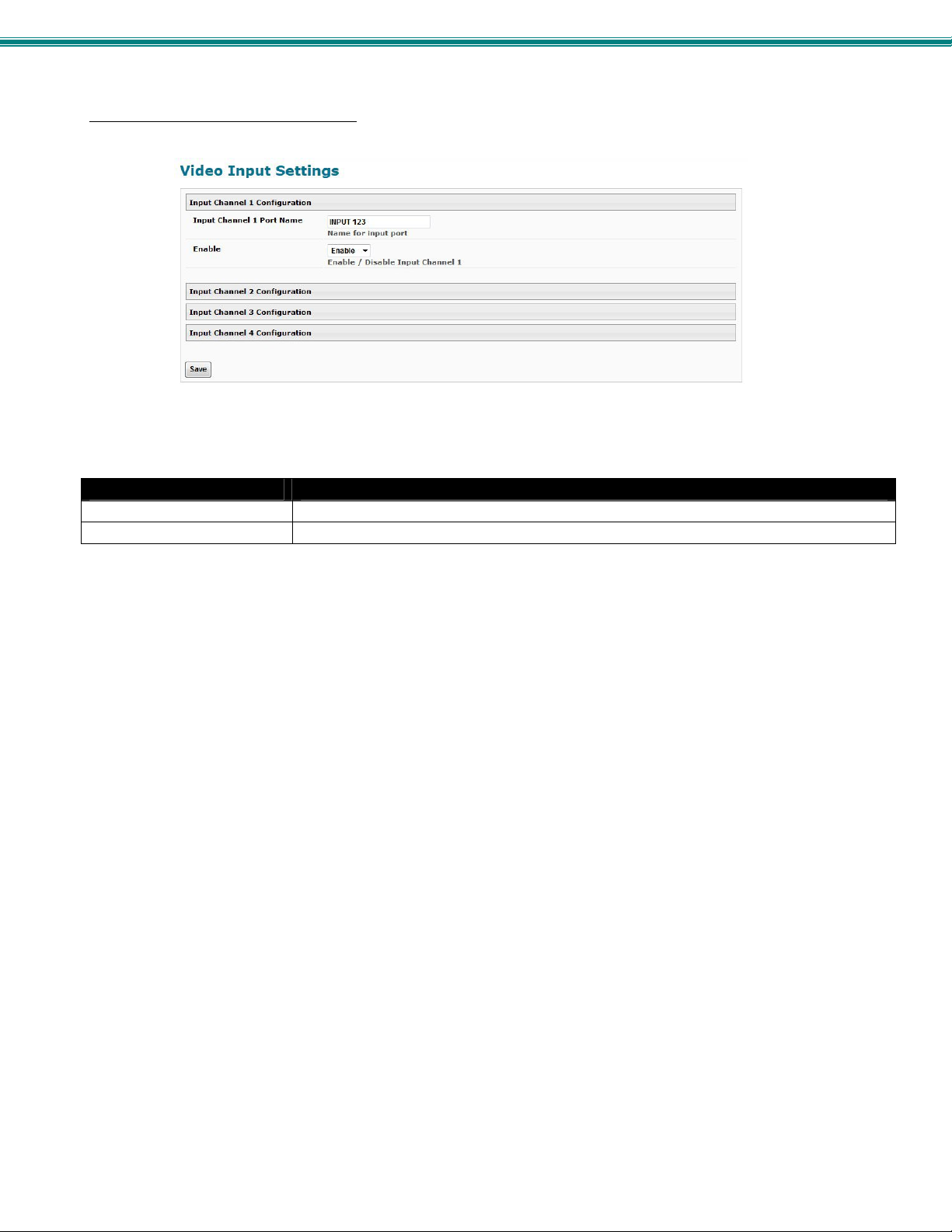
Figure 21- Input Settings
Input Settings Description
Input Channel x Port Name Enter a port name to associate with the video source on Input 1
Enable Choose to Enable or Disable the video input for this channel
Each Input channel can be configured with these settings.
Note: Make sure the input channel port names contain at least 7 characters (including spaces) or they will not be
controllable through the Serial/Telnet interface (page 38).
21
Page 28
SPLITMUX Quad Screen 4K Multiviewer
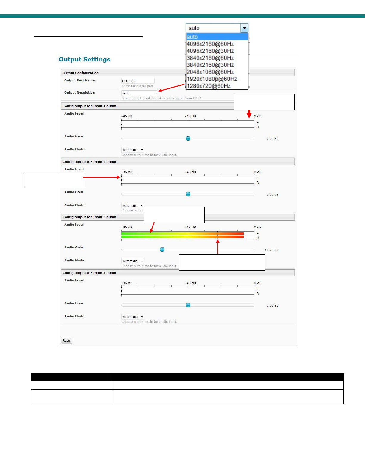
Administration- Output Settings
Indicates no audio
at source
Maximum
recommended level
Colors show input
volume from source
Arrows indicate output
volume through SPLITMUX
Figure 22- Output Settings
Video Output Configuration Description
Output Port Name Enter a port name to associate with the display
Output resolution Select the output resolution to send to the display or select “Auto” to have it choose from the
EDID table.
Note: When the Output resolution is set to “Auto”, your SPLITMUX will automatically sense the native resolution of your
monitor and set the output resolution to that when powering ON the SPLITMUX.
22
Page 29
SPLITMUX Quad Screen 4K Multiviewer
Audio Level and Gain
The Audio level bar indicates the sound level output for the left and right speakers of that input chann el. T he level “ -96dB”
indicates minimum sound output and “0dB” indicates maximum sound output. The audio level can also be viewed on the display
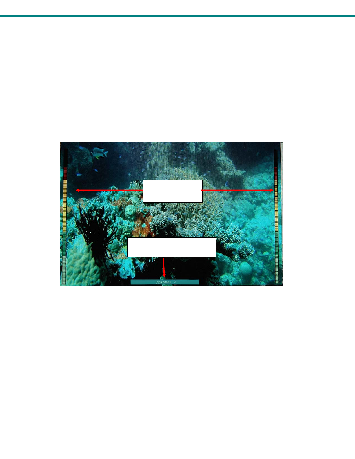
(see Figure 23) when enabled through the web interface (see Figure 26).
The Audio Gain provides control over the Audio level output by the SPLITMUX. Drag the slide button to the left or right to adjust
the audio level. If the Audio level indicates -96dB for an input channel, it means there is no audio at that source.
Note: If sliding the Audio Gain button towards 0.00 dB results in the Audio level reaching 0 dB, back it down towards
the left enough to reduce the Audio level to at least -3dB (red arrow in Fig. 20.). Levels higher than 0dB will likely result
in significant audio static or noise.
Note: The audio that is heard is determined by the Audio Mode Settings (below) and the Input Channel selected under
Current Output Mode (page 17).
Sound level
indications for left
and right speaker
Channel label
(when UMD is enabled (Fig. 24))
Figure 23- Display with sound level indications
Audio Mode Settings
When Audio Mode is enabled, the audio will come through any time the in put signal is present (whether the video is enabled or
not).
When Audio Mode is disabled, no audio will be heard from that input.
When Audio Mode is automatic, the audio will only be heard from that input if that input is the currently active input. To avoid
confusion from multiple audio inputs when using Quad or PIP modes, set each audio input to automatic.
23
Page 30
SPLITMUX Quad Screen 4K Multiviewer
Administration-Mode Settings
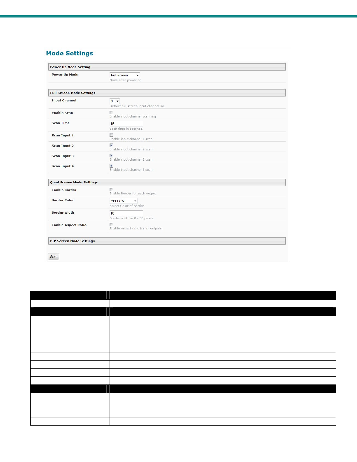
Figure 24- Mode Settings
Power Up Mode Setting Description
Power Up Mode Choose the mode the SPLITMUX will be in when powered ON
Full Screen Mode Settings Description
Input Channel Select the input channel assigned to Full Screen
Enable Scan Enable scanning for the full screen input channel- to automatically switch from one channel to
another
Scan time Set the dwell time while scanning- the amount of time (in seconds) each channel will appear
at full screen- range is 0-999
Scan input 1 Enable or disable to include input 1 in the scanning sequence
Scan input 2 Enable or disable to include input 2 in the scanning sequence
Scan input 3 Enable or disable to include input 3 in the scanning sequence
Scan input 4 Enable or disable to include input 4 in the scanning sequence
Quad Screen Mode Settings Description
Enable Border Place a border around each input displayed
Border Color Choose the color of the border around each input
Border Width Choose the width of the border around each input- from 0-50 pixels
Aspect Ratio enable to maintain the aspect ratio for each displayed image
Note: Quad Screen Mode will work but the Settings will not be applicable when the Output Setting is set above 1080p.
24
Page 31
SPLITMUX Quad Screen 4K Multiviewer
Note: PIP Screen Mode will not
support resolution above 1920x1080p.
If resolution is set above 1080p, the
SPLITMUX will only output 1080p
resolution while in Custom mode.
Note: Make sure INPUT 1 has a
source connected when enabling
Scan function in PIP Screen Mode
Figure 25- PIP Screen Mode Settings
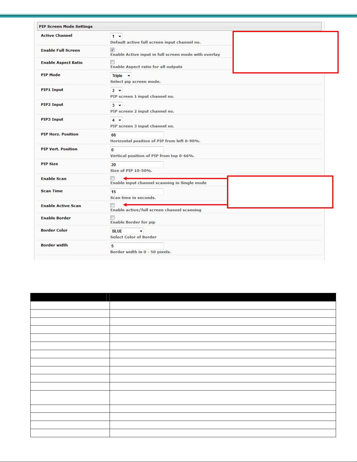
Pip Screen Mode Settings Description
Active Channel Select which active channel is in full screen mode
Enable full screen Enable active input in full screen mode with overlay
Enable aspect ratio Enable to maintain the aspect ratio for all displayed images
PIP Mode Select how many PIP images will b e displayed, 2, 3 or 4 (one will be at full screen)
PIP 1 Input Select which input channel will be in PIP up per right position
PIP 2 Input Select which input channel will be in PIP center position
PIP 3 Input Select which input channel will be in PIP low er right position
PIP Horz. Position Position of PIP images from the right side of the screen- range is 0-90% of screen width
PIP Vert Position Position of uppermost PIP from the top of the screen- range is 0-60% of screen height
PIP Size Size of the PIP image- range is 10-50%
Enable Scan Enable input channel scanning when PIP Mode is set to “Single”
Scan Time Set the dwell time while scanning- the amount of time (in seconds) each channel will appear in
the single PIP position- range is 0-999
Enable Active Scan Enable full screen scanning between the inputs while in PIP mode
Enable Border Place a border around each input displayed
Border Color Choose the color of the border around each input
Border Width Choose the width of the border around each input- from 0-50 pixels
25
Page 32
SPLITMUX Quad Screen 4K Multiviewer
y
Administration- Custom Settings
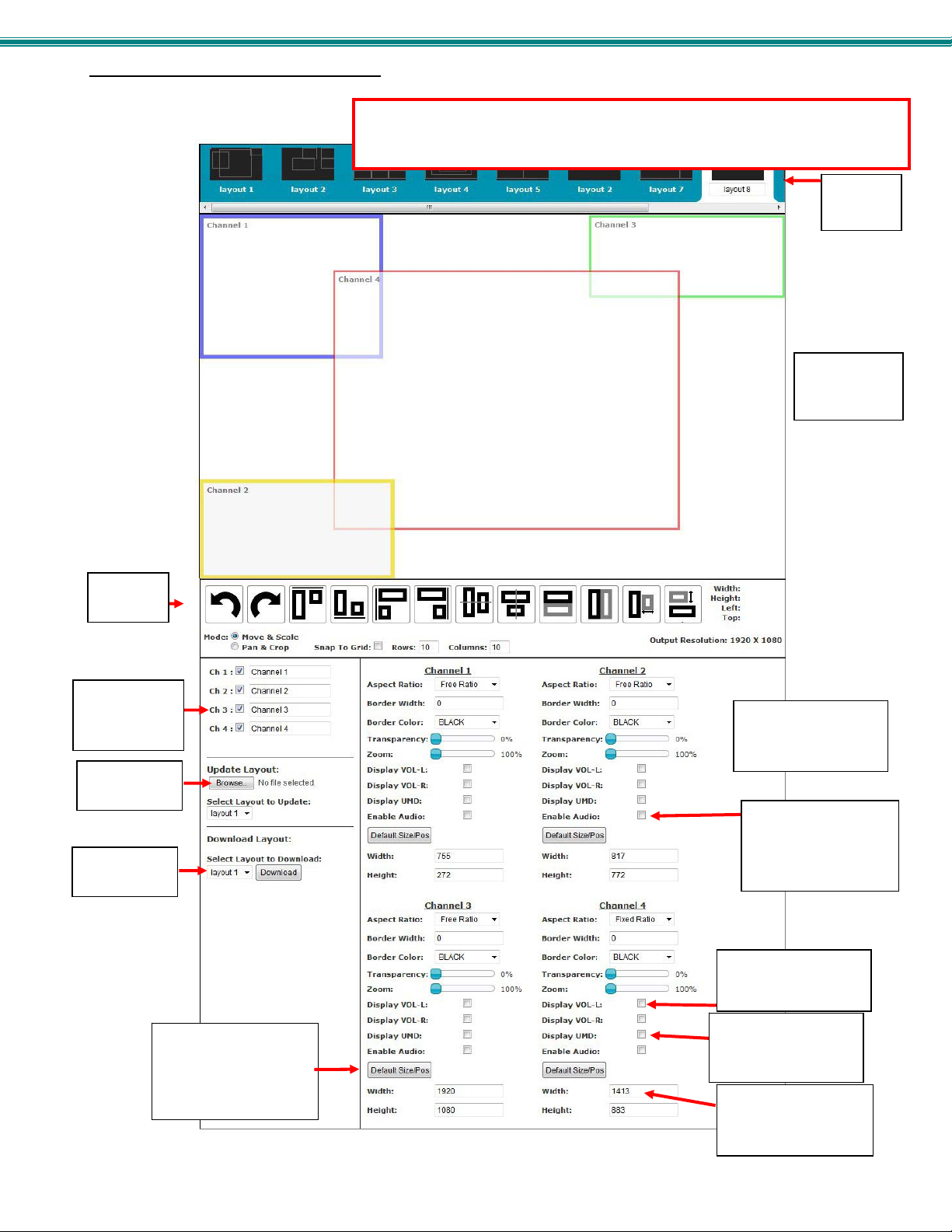
Using the Custom Mode Settings page (Figure 26) you can customize how you want the video from each channel to appear on
the display.
Alignment
Tools
Enable/Disable
and Label each
channel
Restore saved
layout
Download to
save layout
Restore to full screen at
either native resolution
or a combination of
output and native
(whichever is lower)
Figure 26- Custom Screen Mode Settings
Note: Custom Screen Mode will not support resolution above 1920x1080p. If
resolution is set above 1080p, the SPLITMUX will only output 1080p resolution
while in Custom mode.
10 Preset
Layouts
View of display
positions by
channel
Configure the size,
position, appearance
of each input channel
Turn ON/OFF audio
for each channel
(effects Custom Mode
performance only)
Show audio levels for
the channel on the
displa
Enter checkmark to
show channel label
on the display
Enter image size
parameters for each
channel
26
Page 33
SPLITMUX Quad Screen 4K Multiviewer
Preset Layouts and Display Preview
You can use any of the 10 preset layouts (use the slide bar to scroll to 9 and 10) or you can change the presets to a custom
configuration and save those as well.
The window below the presets provides a preview of the spacing of each channel on the display.
When you click on a channel within the window, the box will turn grey to indicate it has been sel ected. W hile sel ected, you can
click and drag any point on the border to resize the channel. Click within the channel and drag to relocate the channel on the
display.
Note: If you click on a channel that covers another channel (bringing the selected channel to the front) , you won’t be
able to re-select the covered channel unless you either move the selected channel or click th e d isab le/en ab le block for
the covered channel to bring the covered channel to the front ag ain.
Alignment Tools
Alignment tools enable the user to select two channels and quickly have them positioned in relationship to each other. Select one
channel, press the <Ctrl> key and select another channel. Then click an alignment tool. The second channel will move in
relationship to the first channel based on the tool you selected. Select Undo or Redo to reverse or repeat an action.
Enter a checkmark in “Snap To Grid” to manually drag channels to invisible grid points for easy alignment of the displayed
images. The distance between grid points is adjusted by changing the numbers of “Rows” and “Columns” (default is 10).
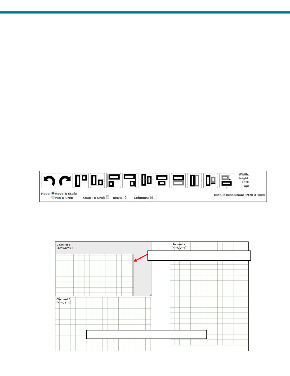
Click the radio button “Move & Scale” (the default) to be able to move the position of the channel on the display. Drag the
corners of the channel to change the size of the displayed image in relationship to your selected aspect ration (See Aspect Ratio
under Channel Settings- page 28)
Click the radio button “Pan & Crop” to enable panning and cropping of the viewed image.
Note: For this to work, the image must first be zoomed (see Channel Settings – page 28).
When “Pan & Crop” is selected, the displayed image will not change in size, but rather your adjustments will change what portion
of the viewed image is visible.
With the image zoomed, use the “Pan & Crop” feature to bring your preferred area of focus into view. When the “Pan & Crop”
feature is enabled, a grid will appear in the web interface to represent the image being adjusted.
Either click and drag the grid itself to pan your view, or click on the edges of the image box (top, bottom, left or right) and drag the
edge in to hide that portion of the image you don’t need to see. (You will want to view the actual display as you do this to see
what portion of the image you are hiding.) When panning, the edges of the grid will tell you where the image e dges are (if you
aren’t looking at the actual display when you adjust this).
Grid pattern in zoomed image with Pan & Cropenabled
Edges of displayed image indicate limits of view.
Figure 27- Pan and Crop Enabled
27
Page 34
SPLITMUX Quad Screen 4K Multiviewer
L
Channel Settings
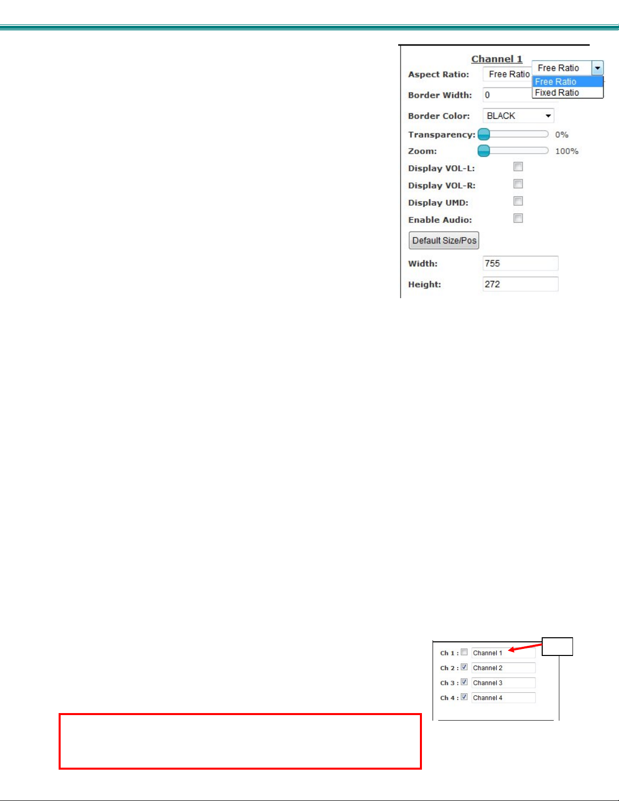
The Aspect Ratio can be configured to be a Fixed or Free Ratio.
When set to Fixed Ratio, no matter what size you drag the channel to be,
the viewed image will retain the ratio of the source.
When set to Free Ratio, the displayed video will adjust to whatever size or
shape you have dragged that channel to be.
To switch between aspect ratio settings, click on the drop-down arrow and select
the desired setting.
Note: When you switch from Free Ratio to Fixed Ratio after having resized
the image, the image on that channel will automatically crop to retain the
displayed size and shape while adjusting to the proper aspect ratio.
The border width can be set from 0-50 pixels (0 = no border).
The border color is selected from an array of options by clicking on the arrow.
Control the level of transparency for an input by sliding the “Transparency” button to the right.
Use the Zoom slider to zoom in on the image to enlarge your view of the source. Zoom range is from 100% (full size) to 500%.
With the image zoomed, you can also use the “Pan and Crop” feature (see Alignment Tools- page 27) to bring your preferred
area of focus into view.
Place a checkmark in “VOL-L” and/or “VOL-R” to display audio levels to the left and right of the video on the display for that
channel. (See Figure 23 on page 23).
Place a checkmark in “UMD” (Under Monitor Display) to show the channel name beneath the video on the display.
Note: The audio level and UMD will only be viewable on the display when the SPLITMUX is in Custom Mode.
Place a checkmark in “Enable Audio” to hear the audio from that channel. Remove the checkmark to disable audio, but this will
only effect audio operation while in Custom Mode.
If your adjustments result in distortions in the channel and you want to start from scratch, click on “Default Size/Pos” button. The
channel resolution will either change to a full screen display at the native resolution for that channel, or to a combination of the
native resolution and the set output resolution of the SPLITMUX. If the output resolution is set smaller than the channel (source)
resolution, then the resulting display image will be limited by the size and aspect ratio of the output setting.
For a specific display dimension for the selected channel, enter the desired values under “Width” and “Height”.
Enable/Disable Channels
You can enable or disable each channel being displayed, and provide labels for the
channels. These labels are displayed in this interface as well as on the display
device when “UMD” (under monitor display) is selected for the channel.
Note: Custom Mode Settings will not support resolution above 1920x1080p. If
resolution is set above 1080p while in PIP mode, the screen will go blank. If set
above 1080p before enabling PIP mode, the resolution will automatically be
reduced to 1080p.
28
abel
Page 35
SPLITMUX Quad Screen 4K Multiviewer
T
Save/Restore Layouts
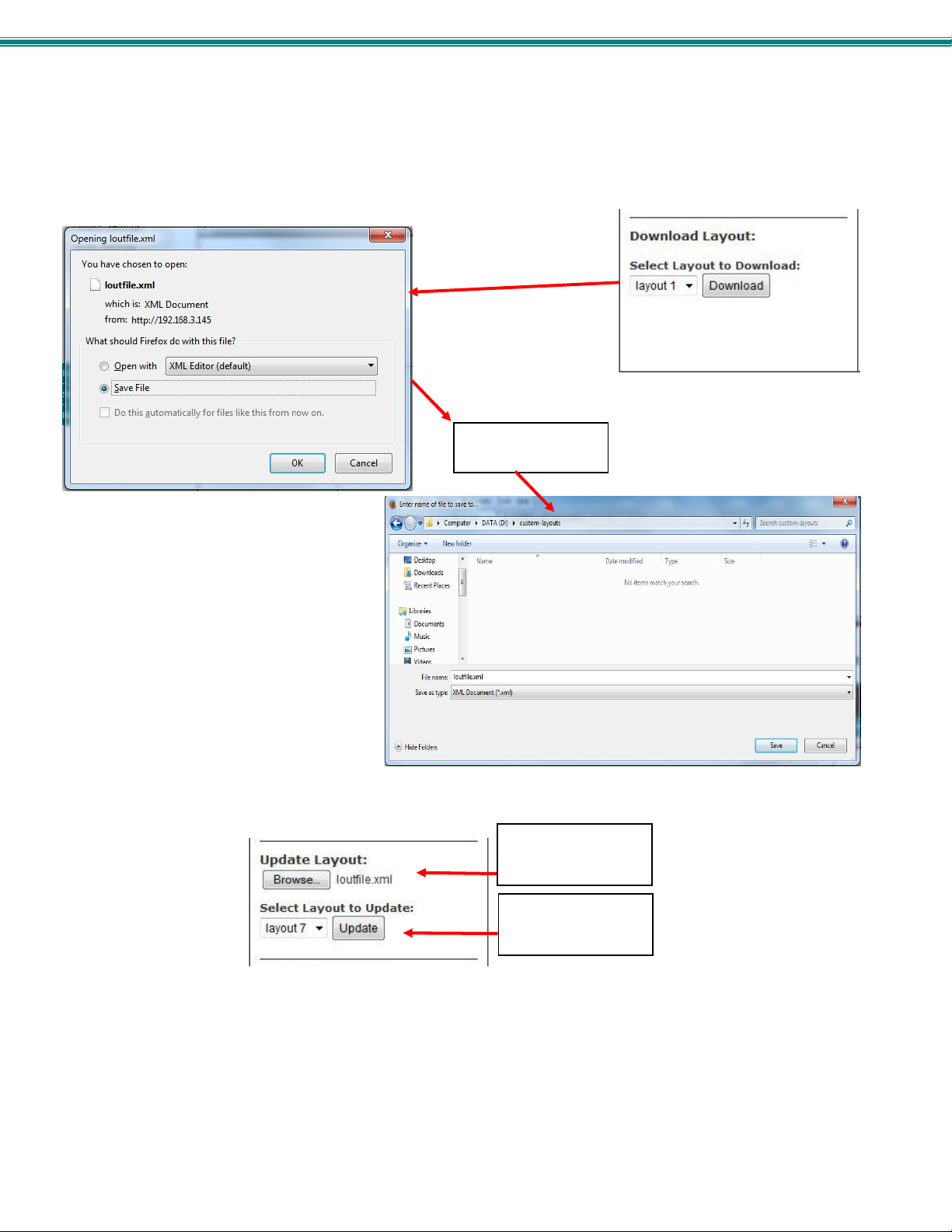
Any customized layout can be saved as a preset. Once you have the desired layout settings, click on “Download” and save the
layout file to a location on your PC.
To replace an existing preset with your custom preset, click on “Browse” under “Update Layout” and select the saved preset file
on your PC. Then select which preset layout to update with your custom layout and click on “Update”.
Note: If you don’t want to overwrite an existing preset, save that layout to a file on your PC before updating the preset
layout with your custom one. This way you can easily restore the preset at any time.
When resetting the SPLITMUX to default settings, all factory defined presets will be restored. Be sure any customized layouts are
saved to your PC before resetting to defaults.
Save the layout file to
a location on your PC.
Browse, locate and
select the saved
layout
hen select the preset
name to update and
click on “Update”
29
Page 36
SPLITMUX Quad Screen 4K Multiviewer
Cascade Settings
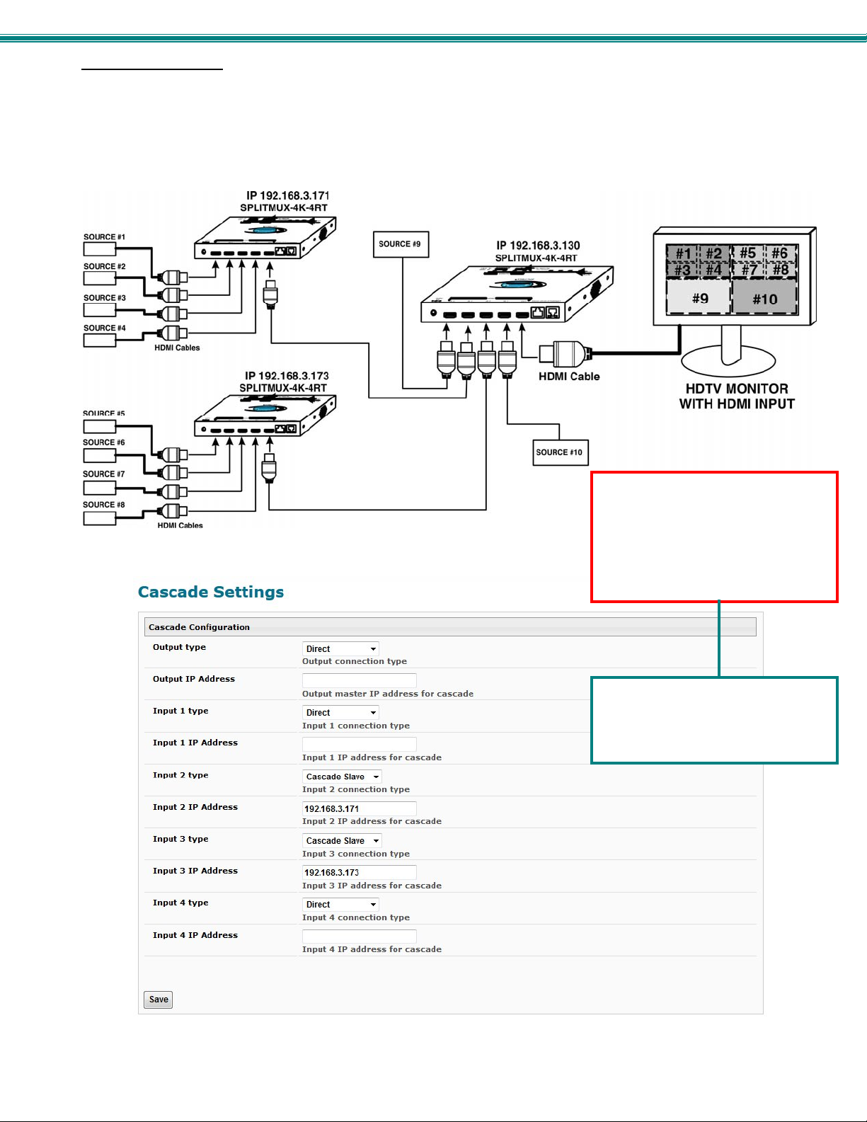
In order to expand the number of video inputs that can be monitored by one display, SPLITMUXs can be connecte d in a cascaded
configuration.
To cascade SPLITMUXs, simply connect the output port of any downstream SPLITMUXs to the input port of an upstream
SPLITMUX. Any input sources will be viewable from the monitor connected at the most upstream SPLITMUX. Using Cascade
Settings under Administration, configure the SPLITMUX for the connection method that will be employed.
Figure 28- Cascading SPLITMUXs
Note: When cascading SPLITMUXs,
make sure the Output Settings of all
slaves are set at or below
1920x1080p. The Input of the
Master does not support higher
resolution settings from the slave
units.
To reduce cost, we recommend
using the SPLITMUX-HD-4RT for any
units connected as Slaves in a
cascaded configuration.
Figure 29- Cascade Settings
30
Page 37

SPLITMUX Quad Screen 4K Multiviewer
Cascade Configuration Description
Output type
Output IP Address When the Output is connected to another SPLITMUX, enter the IP address of that SPLITMUX
Input X (1-4) type
Input X IP Address When the Input is connected to another SPLITMUX, enter the IP address of that SPLITMUX
Be sure to click on “Save” after changing these settings.
Notes:
Each SPLITMUX must be properly configured in the cascade settings in order to view the inputs at the master level.
The Custom Mode layout will display the custom mode layout outline of each slave connected to it.
The Current Mode setting of the slave will determine what video is viewed and audio is heard at the master level, regardless of
what the custom mode layout is set at.
The configuration menu for each slave is accessible from the web interface of the master SPLITMUX with a proper cascade
configuration.
To adjust the custom layout settings for a slave, you must be at the IP address of that slave.
The dotted lines in the custom layout are indication of connection to a slave on that channel of the SPLITMUX. To access that
slave, double-click on the channel image. Allow a few seconds for the screen to update. You will see that the IP address in the
URL bar has updated.
In order to control the configuration of any slave unit from the web interface, that unit must be connected to the LAN through the
Ethernet port. If web interface control is not required for a slave unit, connection to the Ethernet is not required in order to use it
in a cascaded configuration.
With a proper cascade configuration at each level, the IP hierarchy will be displayed in tabs on the Custom Mode Settin gs page.
Direct- port will be directly connected to a display
Cascade Slave- port will be connected to the Input port of an upstream SPLITMUX
Direct- port will be directly connected to a source
Cascade Slave- port will be connected to the Output port of a downstream SPLITMUX
When cascading SPLITMUXs, make sure the Output Settings of all slaves are set at or below 1920x1080p. The Input of
the Master does not support higher resolution settings from the slave units.
For an example of cascading, see page 69.
31
Page 38
SPLITMUX Quad Screen 4K Multiviewer
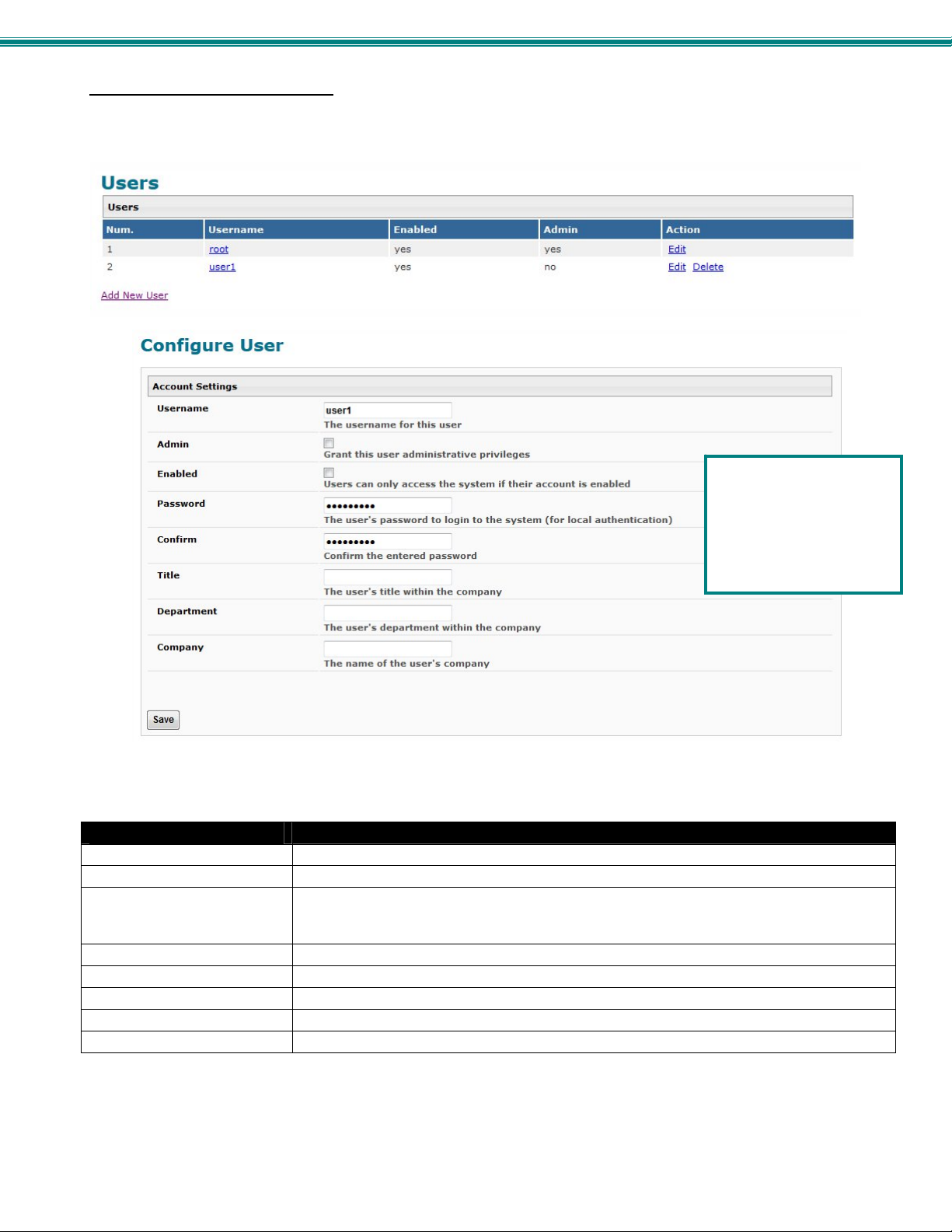
Administration-User Config
Selection of this menu will display a list of all configure users and their status, including the name, if they are enabled to access
the SPLITMUX and if they have basic potentially limited user privileges or full administrative privileges.
Click on “Add new user” to configure up 15 users beyond the “root” user for a total of 16 users.
FYI: Only user “root” can
change the password for
user “root”. An
administrative user can
edit any other user’s
password, except for
user “root”.
Figure 30- User Configuration
Account Settings
Username name the user will use to login
Admin grant this user administrative privileges or not
Enabled enable or disable this users access to the SPLITMUX
Password enter a passwor d for this user to login with
Confirm re-enter the password this user will login with
Title Title of this user in the company
Department Department of this user
Company Name of this user’s company
To edit a user’s settings, double-click on the user name within the list. The “root” username and privileges cannot be changed,
but the root password can be edited. If the root password is changed and forgotten, contact NTI to provide instruction to reset
the password back to “nti”.
Note: a user that is not enabled will not be able to log in to the SPLITMUX
32
Page 39
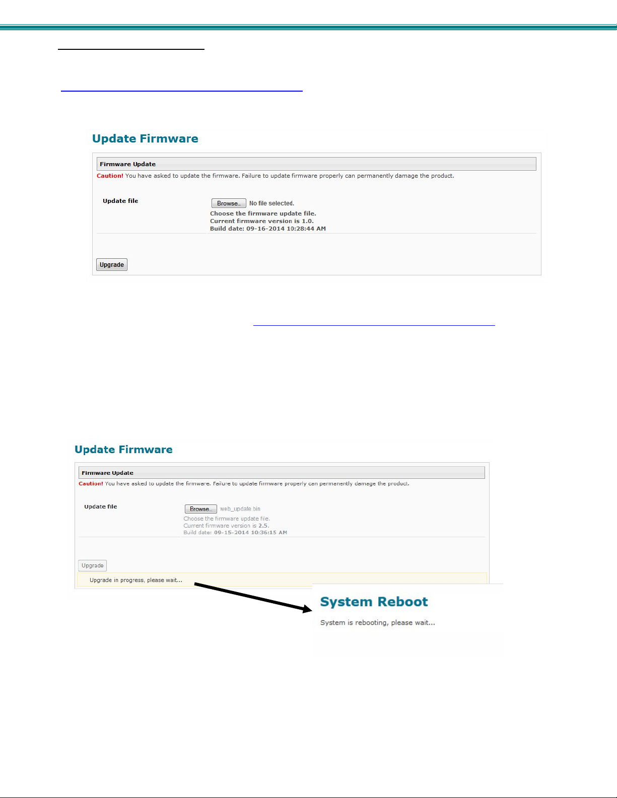
SPLITMUX Quad Screen 4K Multiviewer
Administration- Firmware
The Update Firmware page is used to change the firmware of the SPLITMUX. Occasionally new features or changes to existing
features will be introduced and new firmware with these changes will be made available on the NTI webs ite
(www.networktechinc.com/download/d-hdmi-multiviewer.html
Administration section of the main menu. Once a user has downloaded the required file for firmware upgrade, this page will be
used to upload it to the SPLITMUX.
Figure 31- Firmware Update
1. Download the most current firmware file from www.networktechinc.com/download/d-hdmi-multiviewer.html
to a location on your PC.
2. Click on the “Browse” button and locate and select the firmware file for the SPLITMUX (splitmux-hd-4rt-vx-x.bin,
for example).
3. Click on the “Upgrade” button to perform the firmware update. The firmware update process will take approximately 5 minutes
while the SPLITMUX installs the firmware.
Once the update file has been installed, the unit will automatically reboot. Wait for the SPLITMUX to finish rebooting (5
minutes). Then click on any menu item and the login screen will appear. Login as normal and resume operation.
Note: In the event the SPLITMUX firmware should be corrupted, such that connection through the web interface is no
longer possible, contact NTI for instruction and recovery files to access the SPLITMUX and restore the firmware using a
TFTP server and Terminal connection (page 10).
). To view the Update Firmware page, select Firmware in the
33
Page 40
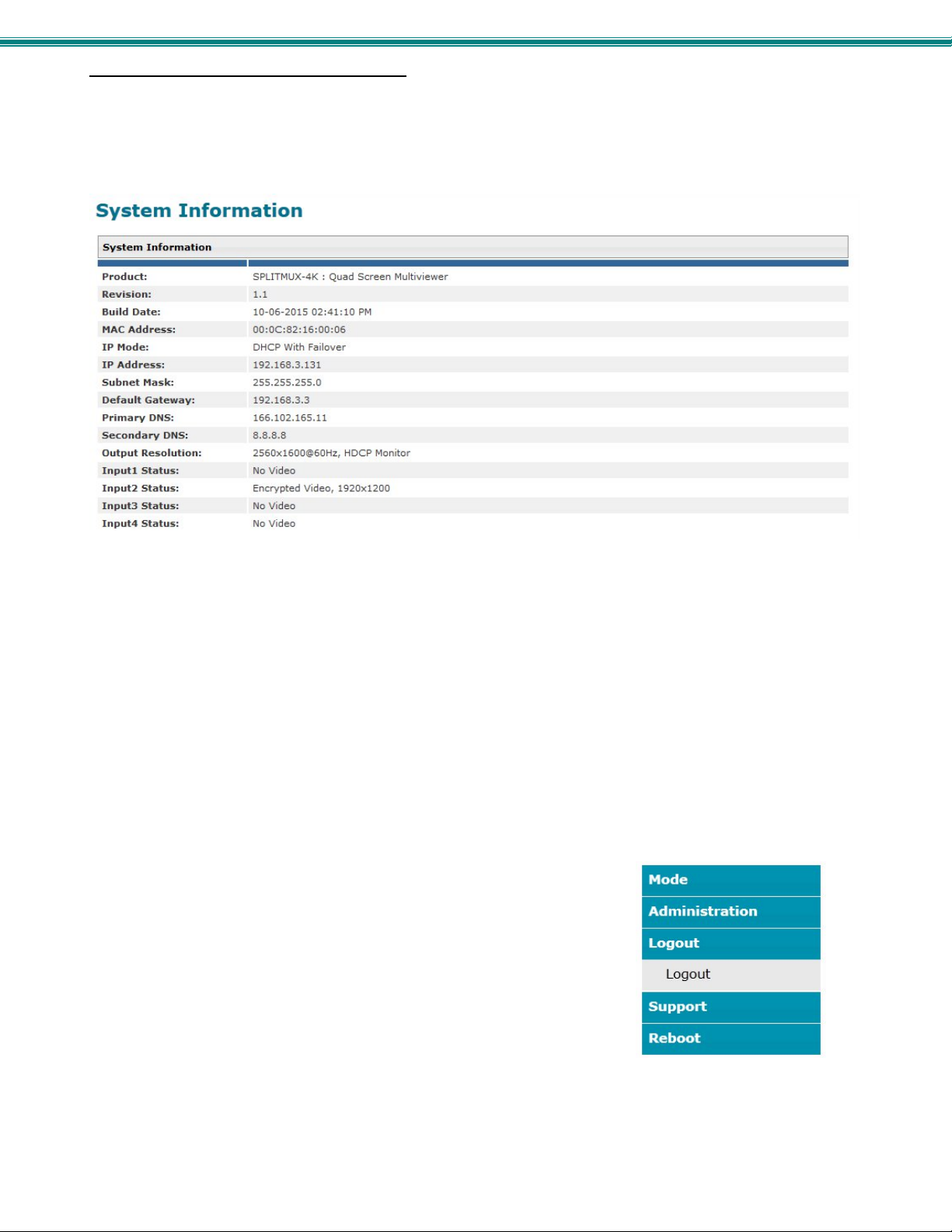
SPLITMUX Quad Screen 4K Multiviewer
Administration- System Information
The System Information page provides firmware version, serial number (version 1.1 and later), MAC address, network settings
and input connection status for the SPLITMUX. This information is particularly helpful when the IP mode is set to “DHCP With
Failover” (the default setting) because it displays the DHCP server-assigned settings, regardless of the network setting applied on
the Network Configuration page (page 20) which only apply when the IP mode is set to “Static”.
Figure 32- System Information page
Note: The System Information page always shows the assigned IP address whether the IP Mode is set to “Static” or
“DHCP with Failover”. (See page 20) This information is also easily accessed from the OSD screen using the front
panel buttons.
Logout
To logout of the SPLITMUX, click on the Logout link in the left menu.
This will return you to the login screen.
34
Page 41
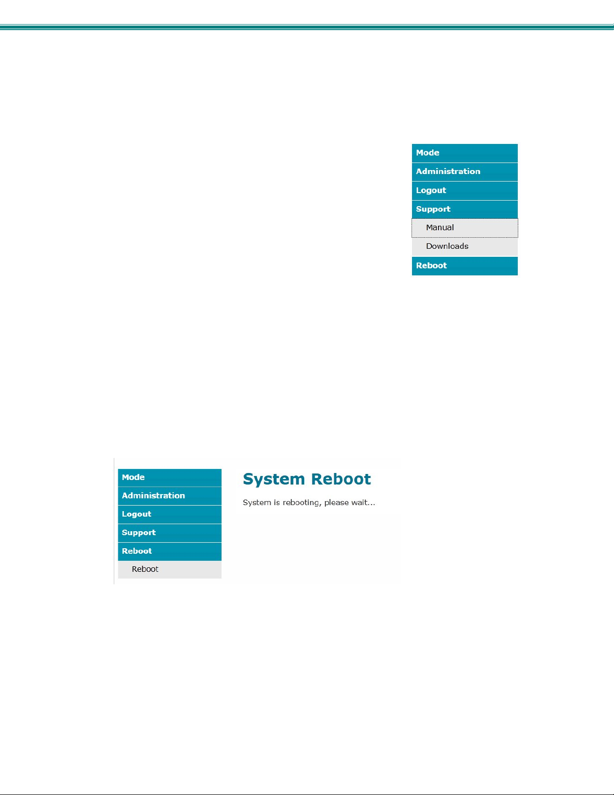
SPLITMUX Quad Screen 4K Multiviewer
Support
The Support section of the menu includes two links, Manual and Downloads.
The Manual link will open the pdf manual for the SPLITMUX on the NTI website.
You must have Adobe Reader installed on your PC to open this.
The Downloads link will take you to the Firmware Downloads page for the SPLITMUX
on the NTI website. All versions of firmware for the SPLITMUX will be found there,
available for immediate download to your PC.
Reboot
To remotely cause the SPLITMUX to reboot and refresh, click on “Reboot” under “Reboot” in the side menu.
The SPLITMUX will immediately log any users out and reboot the SPLITMUX. Another click on anything in the side menu will
return you to the login screen.
35
Page 42
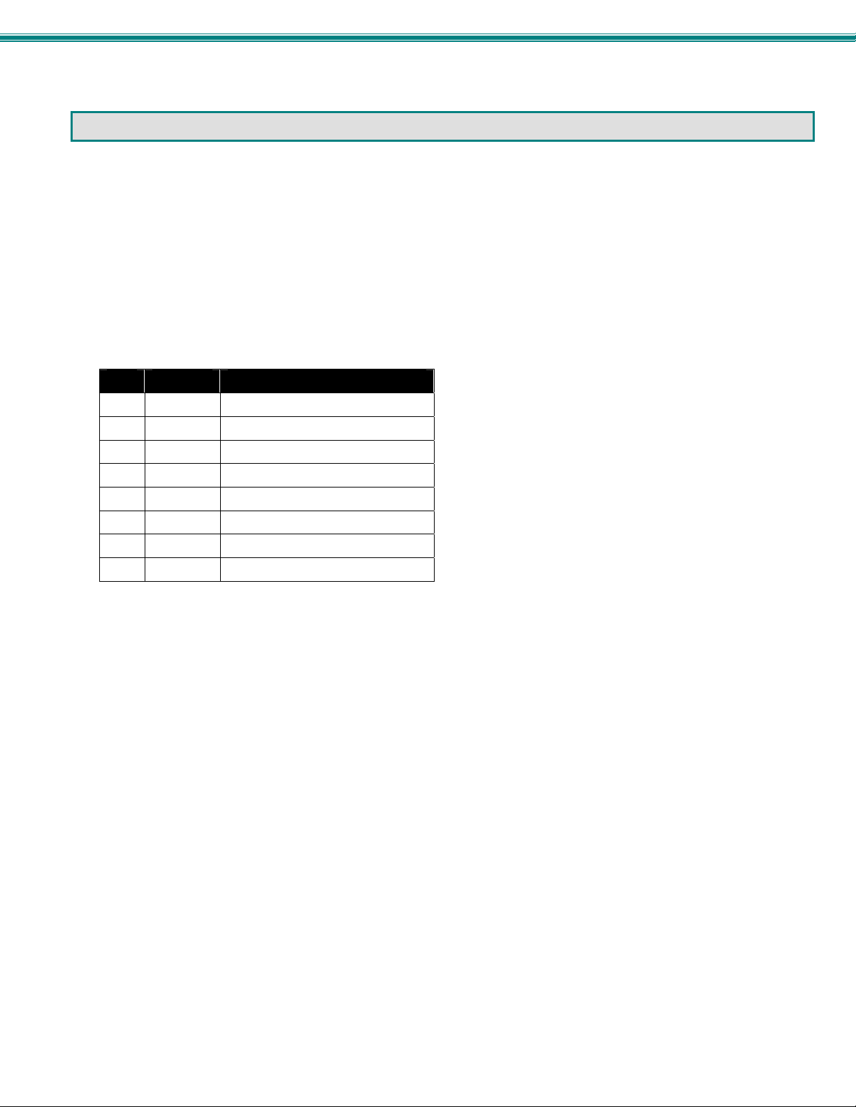
SPLITMUX Quad Screen 4K Multiviewer
COMMAND LINE INTERFACE
The SPLITMUX can be controlled using a command line interface from either a terminal connection to the “RS232” serial port
(page 10) or through an Ethernet connection (page 10).
RS232 Control
The RS232 Interface is designed to meet the RS232C standard and can be controlled from any CPU or other contro ller with an
RS232 communications port. The pin-out for the RJ45 connector on the unit is as follows:
RS232 (RJ45) CONNECTOR
PIN SIGNAL FUNCTION
1 - No connection
2 - No connection
3 RX+ Receive data (TXD at host)
4 GND Ground
5 - No connection
6 TX+ Transmit data (RXD at host)
7 - No connection
8 - No connection
A 5 foot patch cable and adapter, RJ45-to-DB9, have been provided for connection to most CPUs (see page 10).
Baud Rate
The baud rate can be changed using the OSD menu (page 56), using T elnet commands (page 38) from the RS232 commands
(page 37), from the Text Menu (page 42), or through the WEB Interface (page 18). The baud rate can be set to 115200, 57600,
38400, 19200, 9600, 4800, 2400, or 1200. A data protocol of 8 data bits, no parity, and 1 stop bit is used for communications.
The default baud rate setting is 9600. The terminal should be in VT100 terminal mode.
36
Page 43
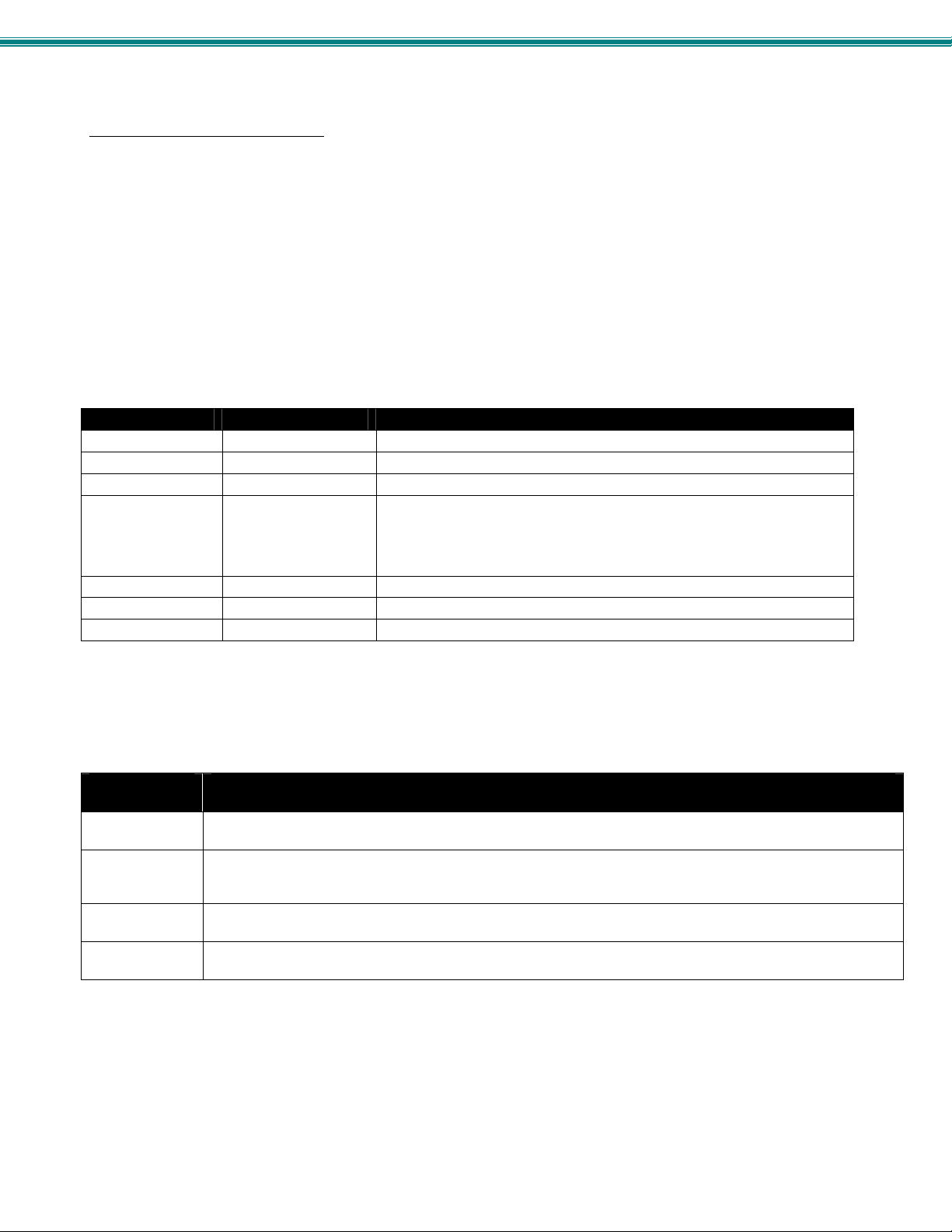
SPLITMUX Quad Screen 4K Multiviewer
RS232 Command Protocol
CPU controller commands supported by the unit are defined below. All commands must be terminated with a <CR> (carriage
return). When a command is sent, the entire string is echoed back along with a response from the addressed unit as shown in the
Command Definitions table (below). All characters in the command string are case sensitive (see Command Definiti ons table),
and all numbers below 10 must have a leading 0 (ex: 1 = 01).
Legend:
(All numbers must be two digits)
SA : Serial Address (01-15)
BR : Baud Rate Code
ip : Input Port (01-04)
Command Definitions
Command String Good Response Description
CS SA,ip,01 *<CR> Connect input X to the output port
CM SA,mode,01 *<CR> Change the mode of the switch
CF SA Login Prompt Open Text Menu
CB 00,BR None
BR=11(5200),57(600),38(400),19(200)96(00),48(00),24(00),12(00)
LA SA,nn *<CR> Load saved custom layout (01-10)
RU SA *<CR>IP,OP<CR> Read Unit Size
RS SA *<CR> Reset unit
If the first field is not a known command (as listed above) or SW field is different from the serial address programmed in the switch
memory, the command will be ignored. If the SW field corresponds to the unit address, but the syntax is wrong after this field, the
switch will answer with a bad response ?<CR>.
Examples:
(From the screen in the Terminal program (HyperTerminal, Putty, etc)
Type, then
press <Enter>
RU 01
CS 01,02,01
CM 01,03,01
CF 01
Action
This will return the unit size. RU must be in upper case. There is a space (press the <Spacebar>) between RU
and 01. 01 is the default serial address of the unit.
This will connect input 2 to output 1. The first 01 is unit serial address; 02 is input 2; the last 01 means output
1. (There is only 1 output, so this value will always be 01). There is a space between letters and numbers,
but a comma between just number values.
This will change output mode to PIP. The first 01 is the serial address. Change as needed for the SPLITMUX
you are controlling. 03 is the mode setting desired (PIP). The second 01 means output 1.
This will bring up the Text Menu for the SPLITMUX with serial address 01. Text menu functions begin on
page 39.
<CR> : Carriage Return (Hex 0xD)
mode : 01 = FULL, 02 = QUAD, 03 = PIP, 04 = CUSTOM
nn : Custom Layout (01-10)
Change baud rate of serial line,
Factory default is 9600
37
Page 44
SPLITMUX Quad Screen 4K Multiviewer
Telnet Control
To control the SPLITMUX using telnet from the command line, the SPLITMUX must first be connected to the Ethernet.
Note: Telnet must be enabled through the web interface (page 20) for a connection via Telnet to be possible.
To open a telnet session to the SPLITMUX
telnet <SPLITMUX IP address> 2000
<SPLITMUX IP address> is IP address of the SPLITMUX (default is
The user will be prompted for the root password to connect to the SPLITMUX.
The factory default password is "nti". (all lowercase letters).
With a proper password sent the SPLITMUX will respond with:
Password Successful
Connection Established
The commands below are now available.
Command String Good Response Description
CS,ip,01 *<CR> Connect input X to the output port
CM,mode,01 *<CR> Change the mode of the switch
CF Login Prompt Open Text Menu
CB 00,BR None
LA,nn *<CR> Load saved custom layout (01-10)
RU *<CR>IP,OP<CR> Read Unit Size
RS *<CR> Reset unit
, Issue the following command from the command line:
Note: When making a Telnet
connection through any terminal
192.168.1.30).
software, be sure to configure to
connect through port 2000.
Change baud rate of serial line,
BR=11(5200),57(600),38(400),19(200)96(00),48(00),24(00),12(00)
Factory default is 9600
38
Page 45
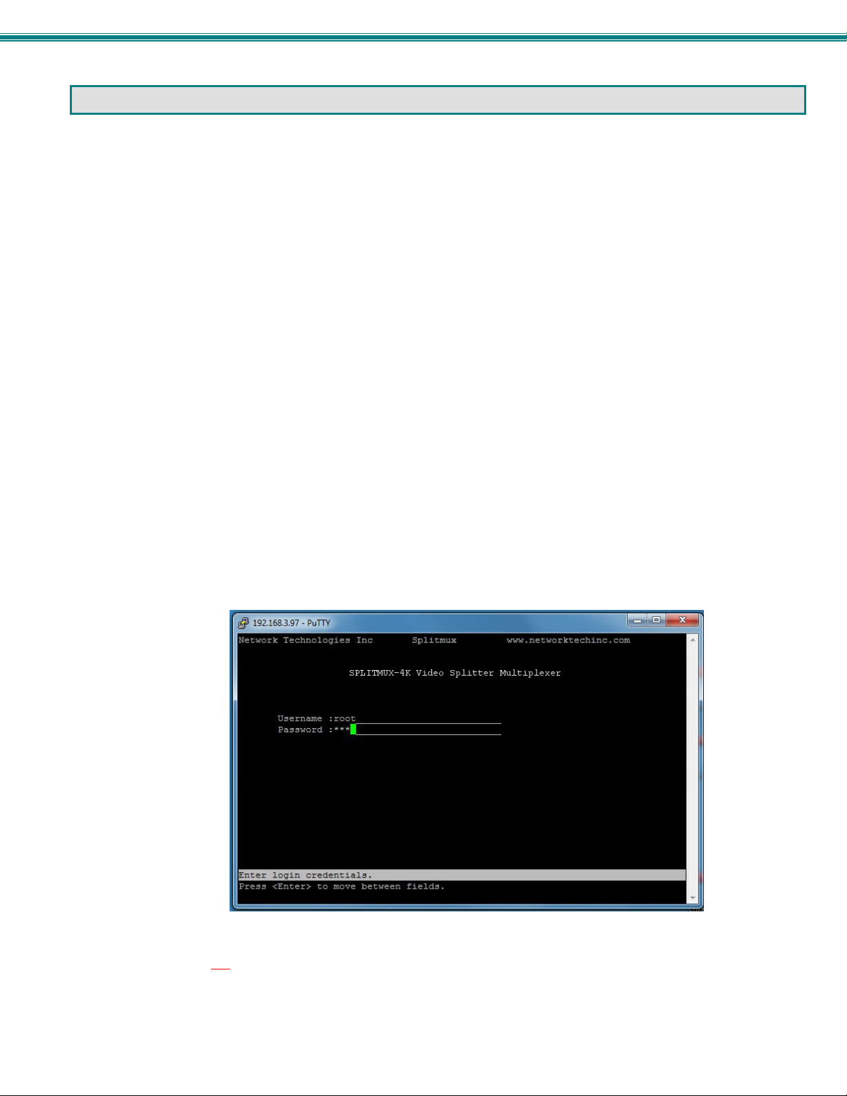
SPLITMUX Quad Screen 4K Multiviewer
USING THE TEXT MENU
The text menu can be reached either by using a serial command through the RS232 port or a Telnet command throug h an
Ethernet connection. Either way, a text menu with full feature control can be reached by any administrative user.
Text Menu Navigation
To move up and down the numbered menu items or toggle through field options, use the arrow keys.
To jump from menu item to another quickly, press the numbered key above the QWERTY keys (the numberpad number
keys are not used).
To move from menu list to action key (such as “Save” in Figure 35), press <Tab>.
To exit an action or menu, press <Esc>.
To select a highlighted item or move to another field in a configuration page, press <Enter>.
Be sure to Tab to “Save” and press <Enter> when configuration changes are made.
To return from “Save” back to a field on the configuration page, press <Tab>.
From a terminal connection to the “RS232” port, enter the command “CF SA” (where SA is the serial address of the
SPLITMUX) and press <Enter>.
From an Ethernet connection through the LAN, enter the Telnet command “CF” (provided you already have a Telnet
connection as described on page 38) and press <Enter>.
You will be presented with a login screen.
1. At “Username” type <
2. At “Password” type <
If you are an administrative user, alternatively enter a valid username and password to also access this menu.
root> (all lowercase letters) and press <Enter>.
nti> (all lowercase letters) and press <Enter>.
Figure 33- Text Menu- Login screen
Note: User names and passwords are case sensitive. It is important to know what characters must be capitalized and
what characters must not
.
39
Page 46
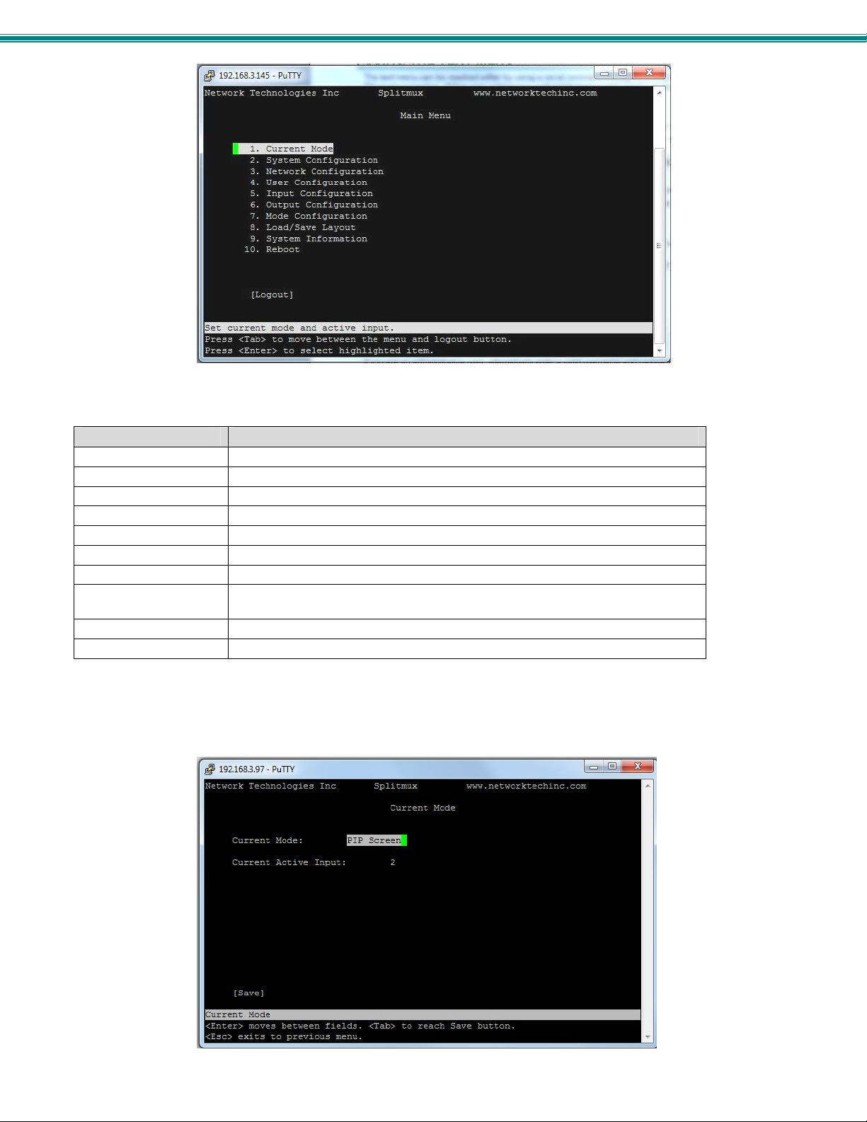
SPLITMUX Quad Screen 4K Multiviewer
Figure 34- Text Menu-Main Menu
The Main Menu is broken into 10 categories:
Function Description
Current Mode Sets the current viewing mode of the SPLITMUX
System Configuration Configure system settings
Network Configuration Configure network settings
User Configuration Configure user access settings
Input Configuration Configure which inputs will be viewed
Output Configuration Configure how the images will appear on the display
Mode Configuration Configure how each mode will behave
Load/Save Layout Choose to save custom layout (up to 10 different layouts) or load one of saved
custom layouts.
System Information Displays information a bout the configuration of the SPLITMUX
Reboot Enables the user to reboot the SPLITMUX
Current Mode
In the Current Mode screen (Main Menu--> 1), set the active mode of the SPLITMUX. This is the mode the SPLITMUX will be in
if the unit is power-cycled. The selected Current Active Input will be the primary input (i.e. when in PIP mode, this will be the
largest image on the screen at power ON.
Figure 35- Text Menu-Current Mode Selection
40
Page 47
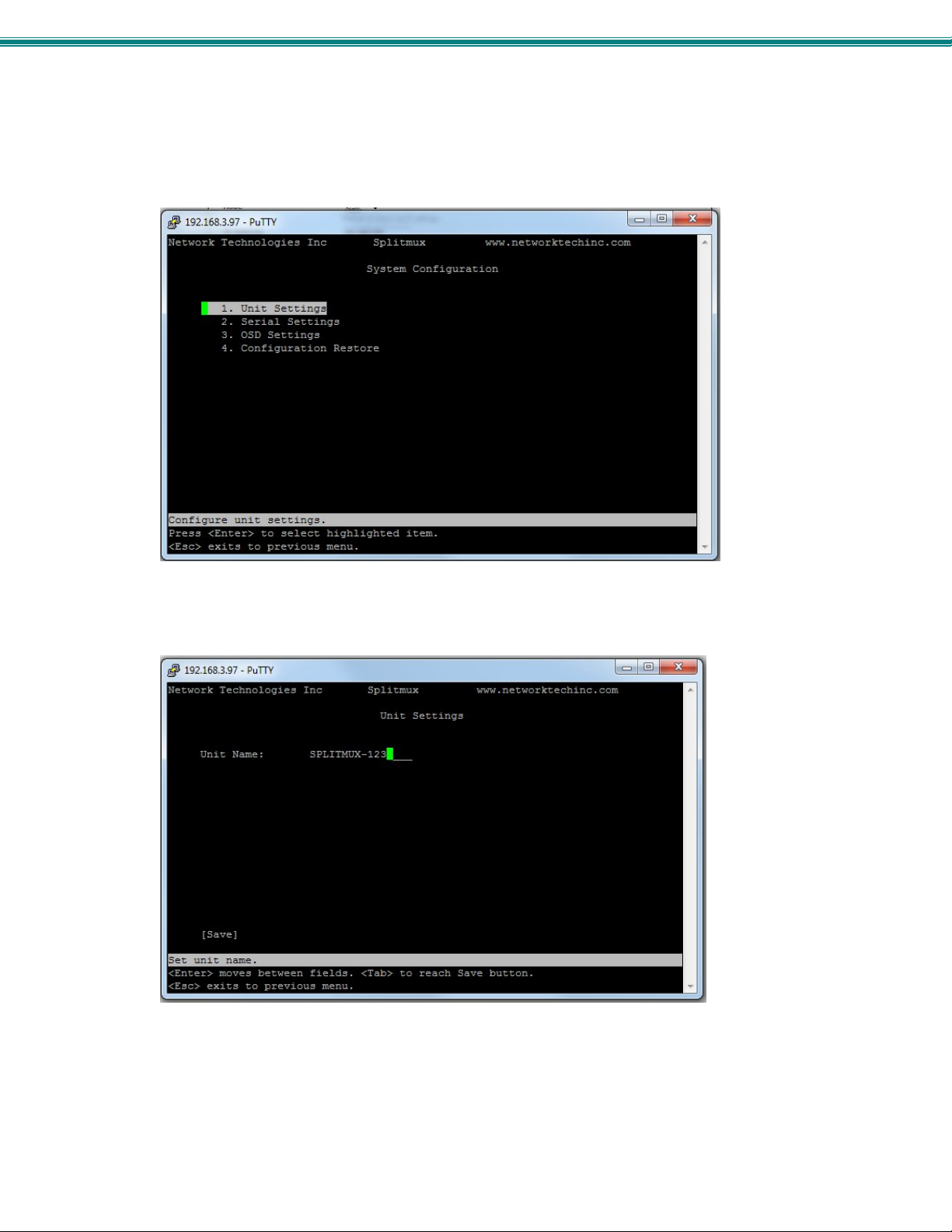
SPLITMUX Quad Screen 4K Multiviewer
System Configuration
In the System Configuration screen (Main Menu—>2) provides 3 categories of settings to configure, and provides an option to
restore the SPLITMUX configuration to default settings.
Figure 36- Text Menu- System Configuration
The Unit Settings page provides a place to enter the name as you want it to appear in the web interface.
Figure 37- Text Menu- Unit Settings
41
Page 48
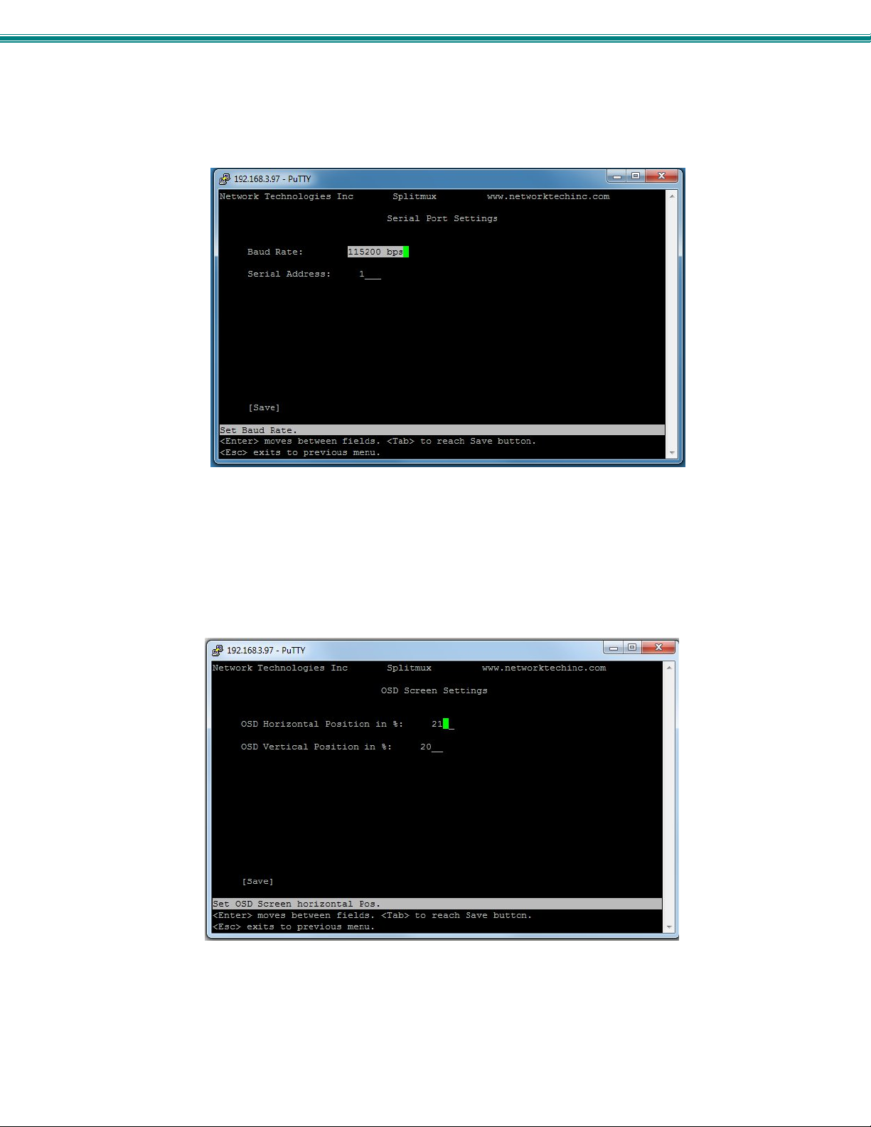
SPLITMUX Quad Screen 4K Multiviewer
Serial Settings page provides configuration of the baud rate (select a value betwe en 1200 and 115200 bps) and the assigned
serial address (1-5).
Figure 38- Text Menu- Serial Port Settings
The OSD Screen Settings page provides values for the placement of the OSD menu on your screen. Values of the Horizontal
and Vertical Position offsets are in percentage of the screen and range from 0 to 70%.
Note: OSD position settings are not applicable when output resolution is set above 1080p. When set above 1080p, the
default values of 10 for Horizontal Position and Vertical position will be in effect.
Figure 39- Text Menu- OSD Screen Settings
42
Page 49
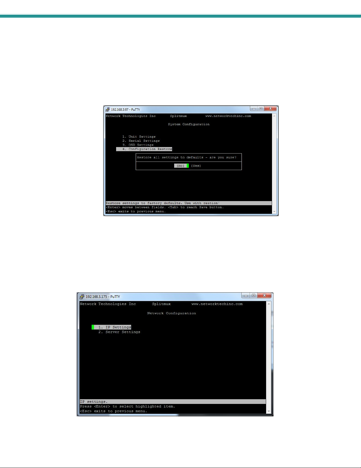
SPLITMUX Quad Screen 4K Multiviewer
If item 4 is selected from the System Configuration menu, you will be prompted for a “Yes” or “No” selection as to whether you are
sure you want to reset all settings in the SPLITMUX to default values, or not. Be careful here, but the default answer is “No” for
your protection.
Figure 40- Text Menu- Restore Default Settings
Network Configuration
The Network Configuration screen (Main Menu—>3) is where all network settings are entered. These settings determine how
you will remotely access the SPLITMUX. Choose between your basic network (IP) settings and several server settings.
Figure 41- Text Menu- Network Configuration
43
Page 50
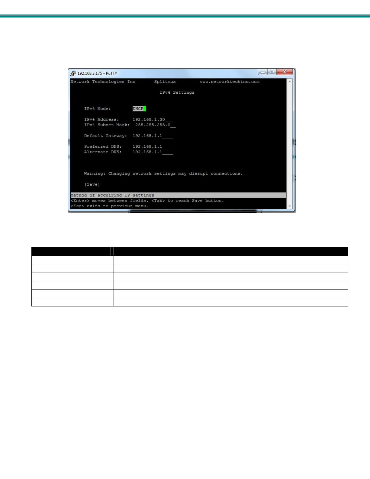
SPLITMUX Quad Screen 4K Multiviewer
The main network settings required to connect the SPLITMUX to your network are found under IP Settings.
Figure 42-Text Menu- IPv4 Network Settings
(Default settings are shown in this image)
IP Settings
Mode Select the method for acquiring IP Settings- Static (manual), DHCP (automatic) or Disable
IP Address
Subnet Mask Enter valid subnet mask (for Static Mode)
Default Gateway Enter valid default gateway (for Static Mode)
Primary DNS Address Enter preferred name server (for Static Mode)
Alternate DNS Address Enter alternate name server (for Static Mode)
Note: If you select “DHCP” for the mode, make sure a DHCP server is running on the network the SPLITMUX is
connected to.
If, upon bootup, the SPLITMUX does not find a DHCP server, the SPLITMUX can be accessed using its default IP address and
network settings (above).
Note: The IP address shown here is only used when the IPv4 mode is set to “STATIC”. To view the IP address when the
mode is set to “DHCP”, go to the “System Information” page (page 54).
Enter valid IPv4 address (for Static Mode) (default is 192.168.1.30)
44
Page 51
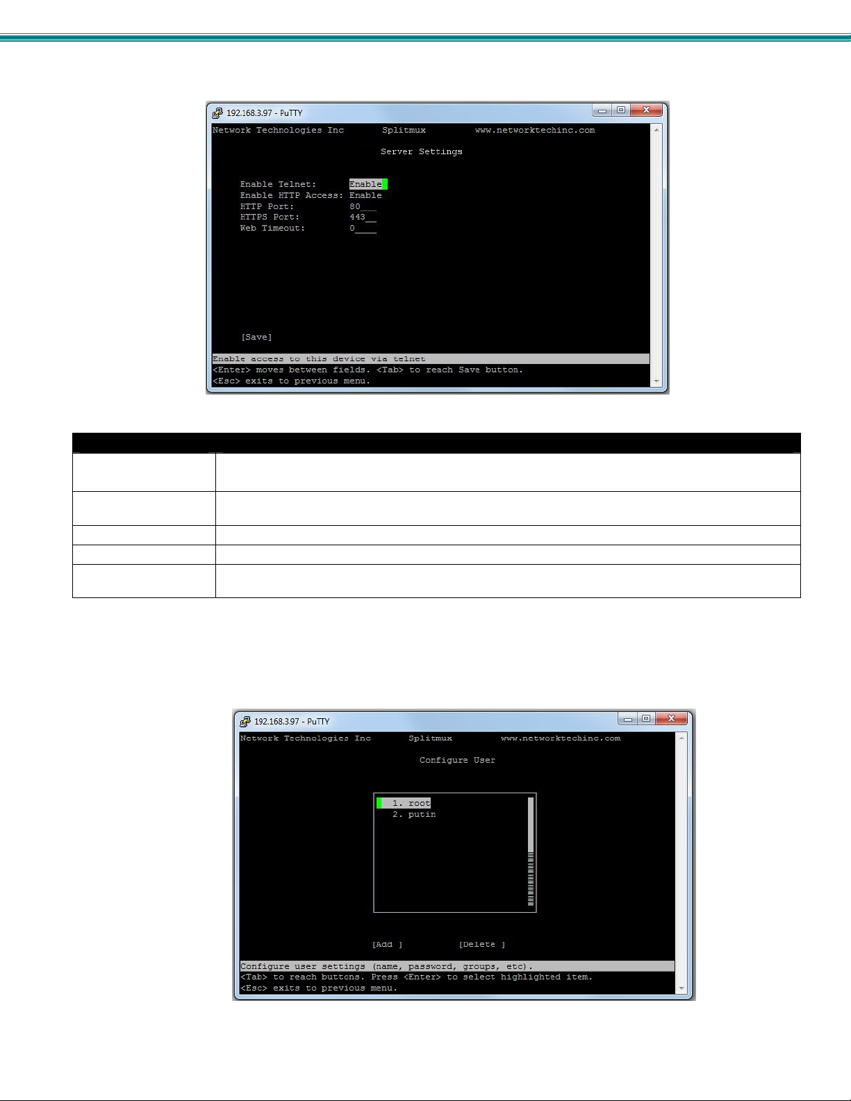
SPLITMUX Quad Screen 4K Multiviewer
Important server settings that determine your ability to connect the SPLITMUX and stay connected are found under Server
Settings.
Figure 43- Text Menu-Server Settings
Server Settings
Enable Telnet Change to “Enable” to permit access to the SPLITMUX via Telnet
The default is disabled.
Allow HTTP access Change to “Enable” to allow access to the SPLITMUX via standard (non-secure) HTTP requests
The default is disabled.
HTTP Port Port to be used for standard HTTP requests (default is 80)
HTTPS Port Port to be used for HTTPS requests (default is 443)
Web Timeout Number of minutes after which idle web users will be logged-out (maximum is 32000, enter 0 to disable
this feature)
User Configuration
The configured users are listed on the Configure User screen (Main Menu—>4). Up to 15 users can be configured to access the
SPLITMUX (16 total including “root”). Select a user and press Enter to edit the user settings, Tab to “Add User” to create a new
one, or Tab to Delete.
Figure 44- Text Menu- Users List
45
Page 52
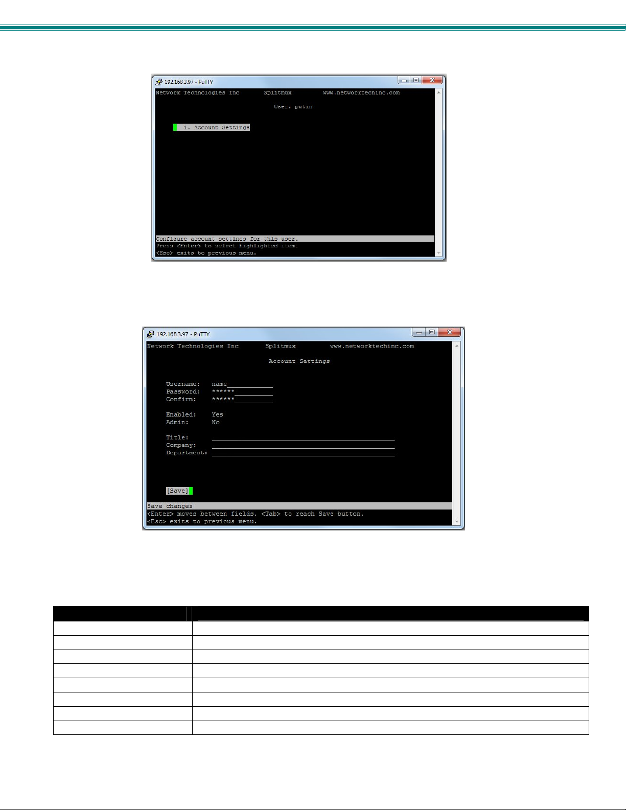
SPLITMUX Quad Screen 4K Multiviewer
Figure 45- Text Menu- Account Settings
Figure 46- Text Menu- User Account Settings
Account Settings
Username enter the name the user will use to login
Password enter a passwor d for this user to login with
Confirm re-enter the password this user will login with
Enabled Yes or No to enable this user to access the SPLITMUX
Admin grant this user administrative privileges - or not
Title Title of this user in the company
Company Name of this user’s company
Department Department of this user
46
Page 53
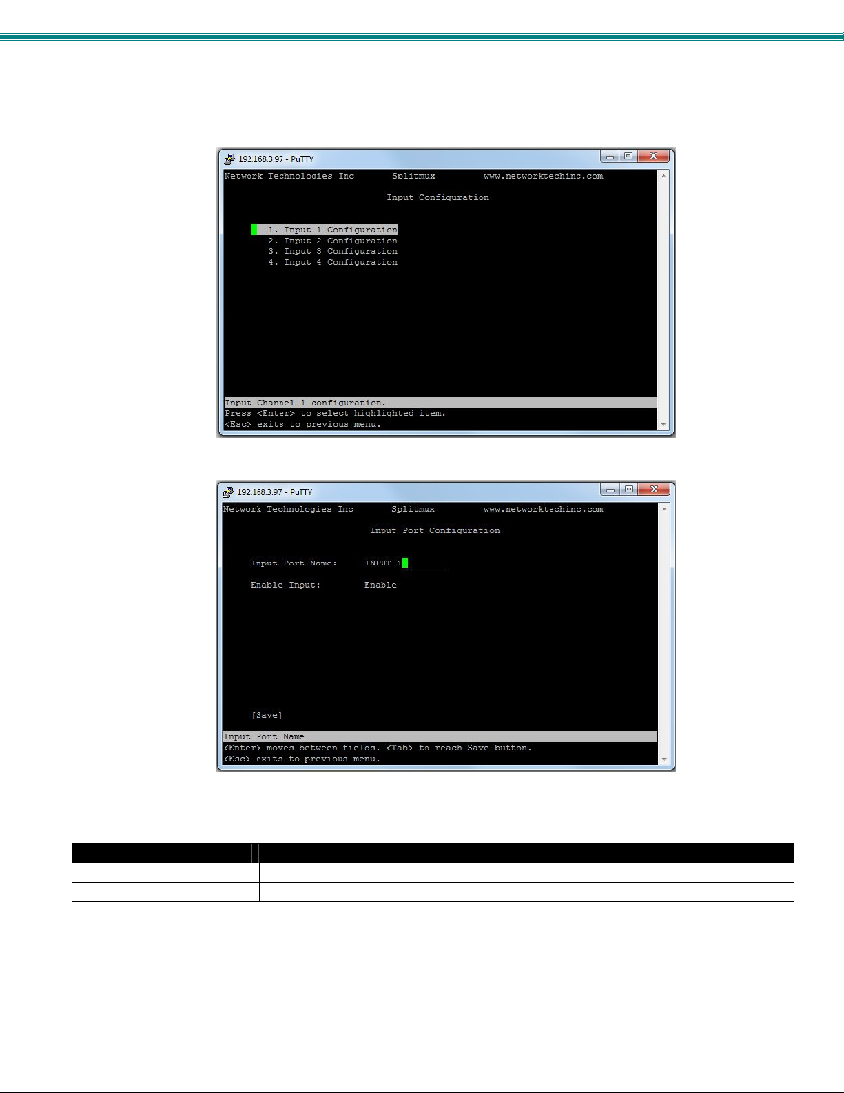
SPLITMUX Quad Screen 4K Multiviewer
Input Configuration
Configure what inputs will be viewed on the display in the Input Configuration screen (Main Menu—>5). Select wh ich input to
configure and choose the settings to be applied.
Figure 47- Text Menu- Input Configuration
Input Settings
Input Channel x Port Name Enter a port name to associate with the video source on Input 1
Enable Choose to Enable or Disable the video input for this channel
Each Input channel can be configured with these settings.
47
Page 54
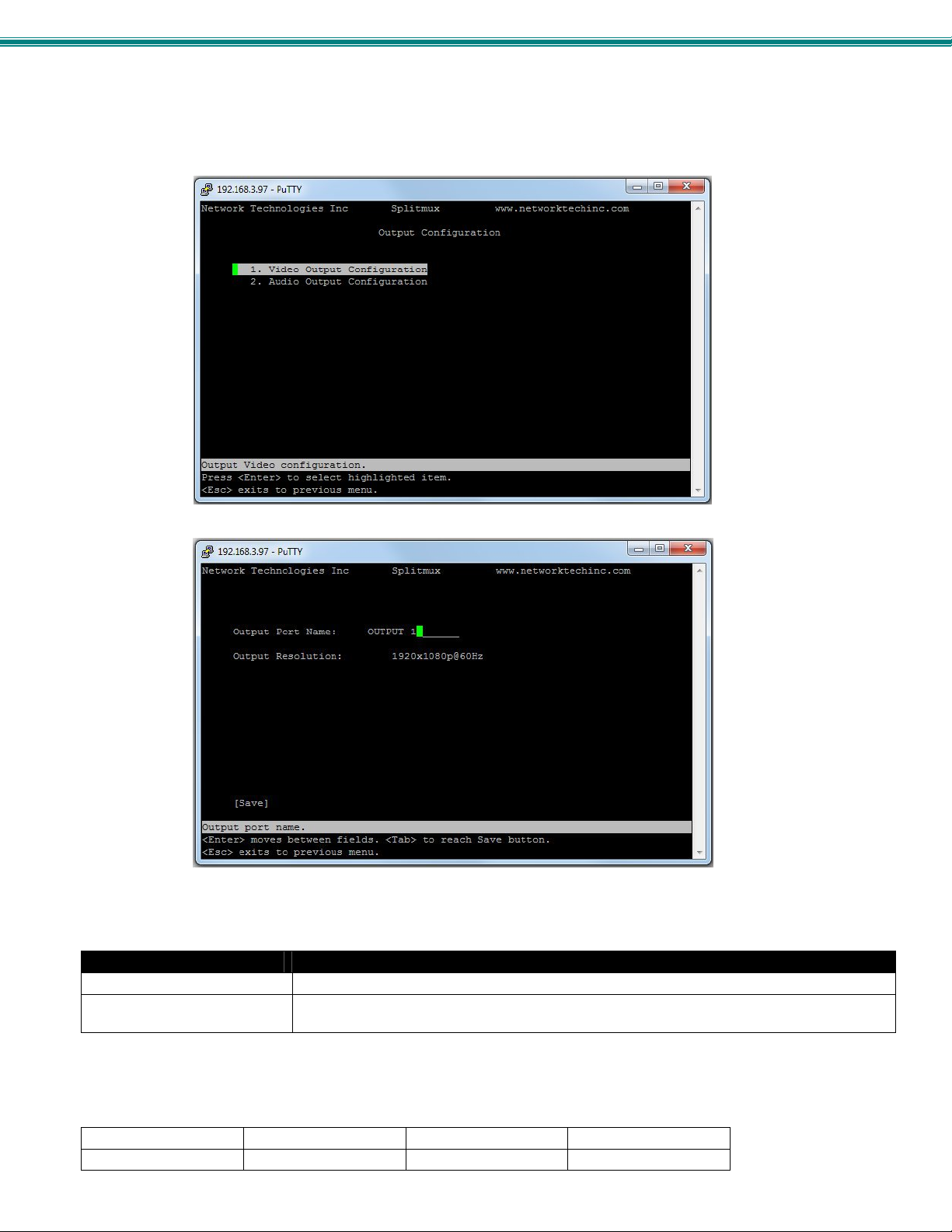
SPLITMUX Quad Screen 4K Multiviewer
Output Configuration
The Output Configuration determines how the inputs will be viewed on the display (Main Menu—> 6). From this menu you can
also select the Audio Output Configuration which will provide settings for how the audio from the inputs is managed.
Figure 48- Text Menu- Output Configuration
Video Output Configuration
Output Port Name Enter a port name to associate with the displ ay
Output resolution Select the output resolution to send to the display (see table below for resolutions to choose
Note: When the Output resolution is set to “Auto”, your SPLITMUX will automatically sense the native resolution of your
monitor and set the output resolution to that when powering ON the SPLITMUX.
Video Output Resolutions to choose from (progressive scan):
1280x720@60Hz 2048x1080@60Hz 3840x2160@60Hz 4096x2160@30Hz
1920x1080@60Hz 3840x2160@30Hz 4096x2160@60Hz
from) or select Auto to have it choose from the EDID table.
48
Page 55
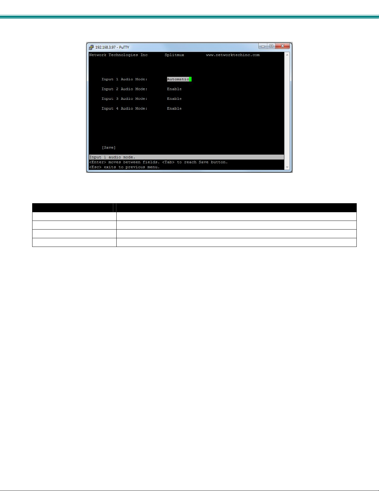
SPLITMUX Quad Screen 4K Multiviewer
Figure 49- Text Menu- Audio Output Configuration
Audio Output Configuration
Input 1 Audio Mode Select the audio mode for the Input- between enabled/disabled/automatic
Input 2 Audio Mode Select the audio mode for the Input- between enabled/disabled/automatic
Input 3 Audio Mode Select the audio mode for the Input- between enabled/disabled/automatic
Input 4 Audio Mode Select the audio mode for the Input- between enabled/disabled/automatic
When Audio Mode is enabled, the audio will come through any time the input signal is present (whether the video is enabled or
not)
When Audio Mode is disabled, no audio will be heard from that input.
When Audio Mode is automatic, the audio will only be heard from that input if that input is the currently selected input. To avoid
confusion from multiple audio inputs when using Quad or PIP modes, set each audio input to automatic.
49
Page 56
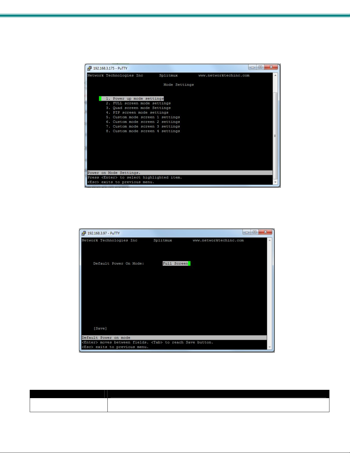
SPLITMUX Quad Screen 4K Multiviewer
Mode Configuration
Mode Configuration (Main Menu—>7) will determine how each display mode provided by the SPLITMUX will be presented.
Mode characteristics will determine how the images will look on the display.
Figure 50- Text Menu- Mode Settings Menu
Figure 51- Text Menu- Default Mode Configuration
Power Up Mode Setting
Default Power On Mode Choose the default mode the SPLITMUX will be in when powered ON. Choose from Full, Pip,
Quad or Custom
50
Page 57
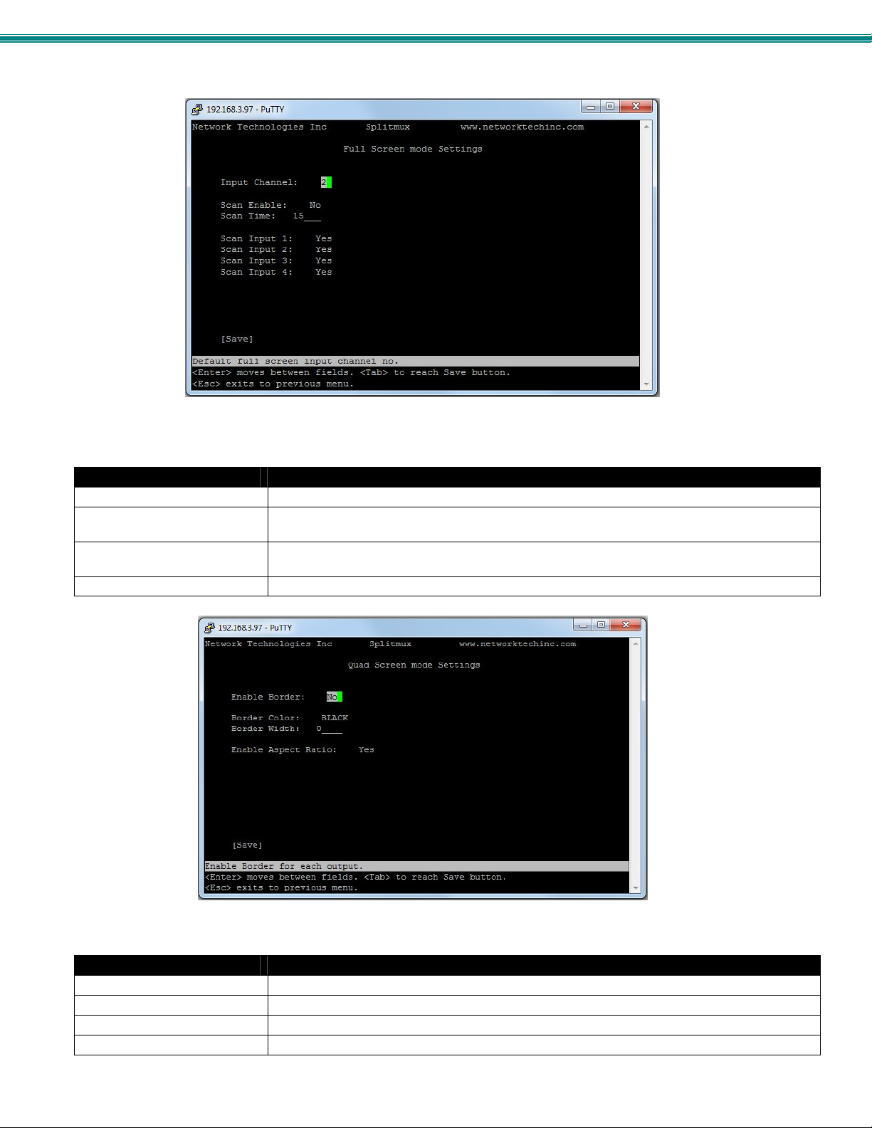
SPLITMUX Quad Screen 4K Multiviewer
Figure 52- Text Menu- Full Screen Mode Settings
Full Screen Mode Settings
Input Channel Select the input channel assigned to Full Screen
Enable Scan Enable scanning for the full screen input channel- to automatically switch from one channel to
Scan time Set the dwell time while scanning- the amount of time (in seconds) each channel will appear
Scan input 1-4 Select Yes or No to include input 1, 2, 3 or 4 in the scanning seq uence
another
at full screen- range is 0-999
Figure 53- Text Menu- Quad Mode Settings
Quad Screen Mode Settings
Enable Border Choose whether or not to place a border around each input displayed
Border Color Choose the color of the border around each input
Border Width Choose the width of the border around each input- from 0-50 pixels
Aspect Ratio Choose whether or not to maintain the aspect ratio for each displayed image
Note: Quad Screen Mode border settings will not be applicable when the output settings are set above 1920x1 080p.
51
Page 58
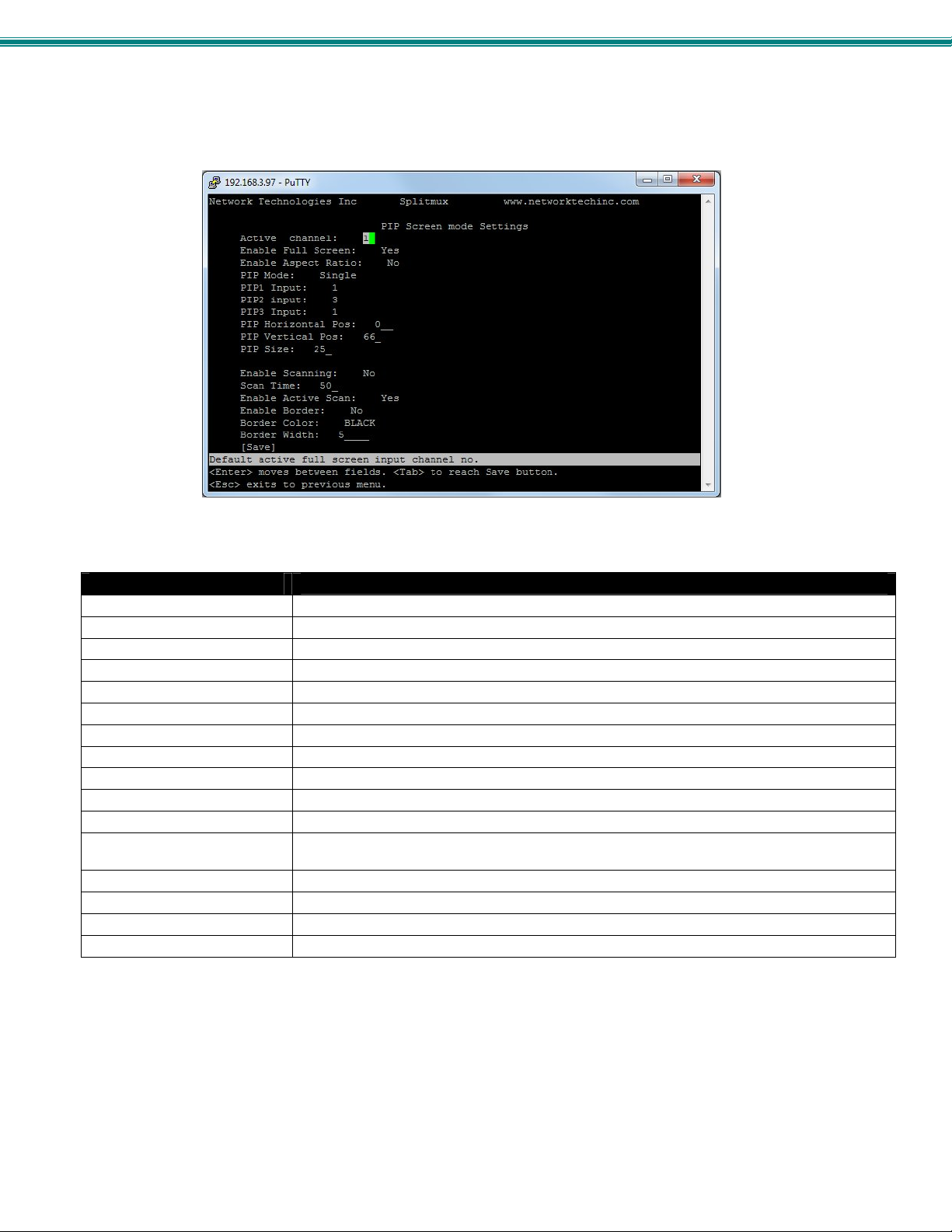
SPLITMUX Quad Screen 4K Multiviewer
Figure 54- Text Menu- PIP Mode Settings
Pip Screen Mode Settings
Active Channel Select which active channel is in full screen mode
Enable full screen Enable active input in full screen mode with overlay
Enable aspect ratio enable the aspect ratio to be maintained for all displayed images
PIP Mode Select how many PIP images will b e displayed, 2, 3 or 4 (one will be at full screen)
PIP 1 Input Select which input channel will be in PIP up per right position
PIP 2 Input Select which input channel will be in PIP center position
PIP 3 Input Select which input channel will be in PIP low er right position
PIP Horizontal Position Position of PIP images from the right side of the screen- range is 0-90% of screen width
PIP Vertical Position Position of uppermost PIP from the top of the screen- range is 0-60% of screen height
PIP Size Size of the PIP image- range is 10-50%
Enable Scan Enable input channel scanning when PIP Mode is set to “Single”
Scan Time Set the dwell time while scanning- the amount of time (in seconds) each channel will appear in
Enable Active Scan Enable full screen scanning between the inputs while in PIP mode
Enable Border Place a border around each input displayed
Border Color Choose the color of the border around each input
Border Width Choose the width of the border around each input- from 0-50 pixels
the single PIP position- range is 0-999
Note: PIP Screen Mode will not support resolution above 1920x1080p. If resolution is set above 1080p, the SPLITMUX
will only output 1080p resolution while in PIP mode.
52
Page 59
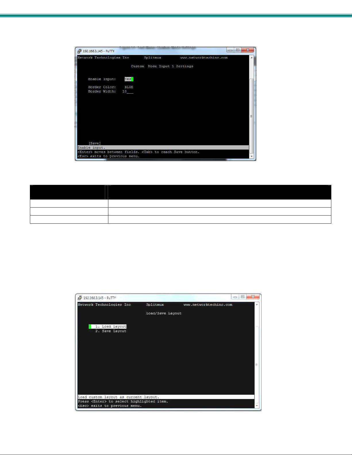
SPLITMUX Quad Screen 4K Multiviewer
Figure 55- Text Menu- Custom Mode Settings
Custom Screen Mode
Settings Input x (1-4)
Enable Input Enter a checkmark to enable the display of the input
Border color for Input Choose the color of the border around each input
Border width for Input Choose the width of the border around each input- from 0-50 pixels (0 = no border)
Note: Custom Screen Mode will not support resolution above 1920x1080p. If resolution is set above 1080p, the
SPLITMUX will only output 1080p resolution while in Custom mode.
Load/Save Layout
Select Load/Save Layout from the main menu (Main Menu—>8) to save or recall a display configuration of video sources being
viewed.
Figure 56- Text Menu- Load/Save Layout
53
Page 60
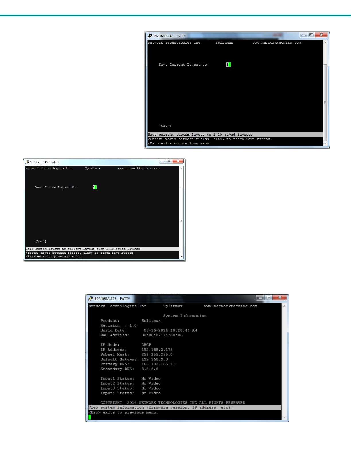
SPLITMUX Quad Screen 4K Multiviewer
Either save your current layout to one of
10 possible saved layouts……
…… or load one of up to 10 previously viewed and saved
layouts.
System Information
Select System Information from the main menu (Main Menu—>9) to view the port status, network configuration, firmware version
and MAC address for the SPLITMUX.
Figure 57- Text Menu- System Information
54
Page 61
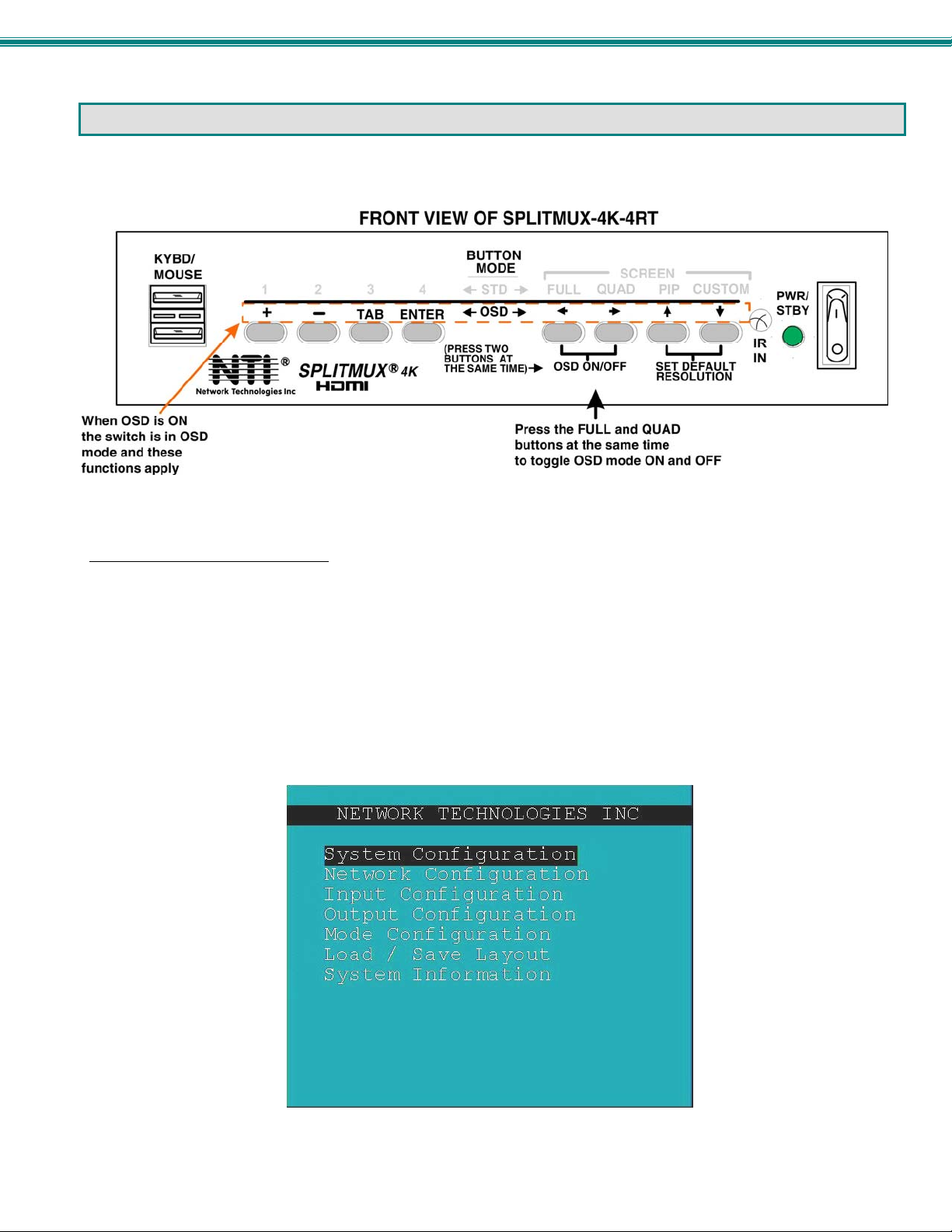
SPLITMUX Quad Screen 4K Multiviewer
USING OSD
In OSD Mode, the front panel buttons are used to navigate and control the SPLITMUX using an on screen display (OSD) menu.
To bring up the OSD menu, press the FULL and QUAD buttons at the same time. To exit the OSD menu, press them again.
Figure 58- Front Panel Button OSD Functions
Navigating the OSD menus
While the OSD menu is on the display, the front panel buttons have the following functions:
The “ENTER” button is used to execute a choice, like pressing the <Enter> key on the keyboard.
The “TAB” button is used to move from one field to another in the menus.
The “+” button is used to advance the field to another option, or increase a numeric value by one.
The left, right, up and down arrows are only used in the OSD position screen to move the OSD screen to a different location on
the display. As an arrow is pressed, the value of the horizontal or vertical position will increase or decrease as the OSD menu
also moves in response to the button press.
TAB to “Save” and press ENTER to record your changes in the SPLITMUX.
TAB to “Cancel” and press ENTER to ignore and cancel any changes that were made
The “–“ button is used to decrement the field to another option, or decrease a numeric value by one.
Figure 59- The OSD Menu
55
Page 62
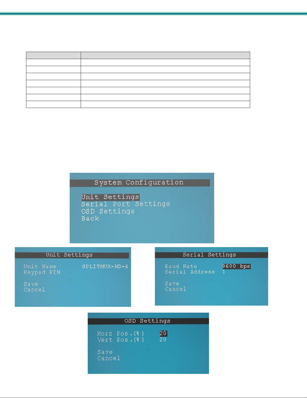
SPLITMUX Quad Screen 4K Multiviewer
Most of the settings that can be changed using the web interface and text menus can also be changed using the OSD menus.
Function Description
System Configuration Configure system settings
Network Configuration Configure network settings
Input Configuration Configure which inputs will be viewed
Output Configuration Configure how the images will appear on the display
Mode Configuration Configure how each mode will behave
Load/Save Layout Load or Save Custom Layout configurations
System Information Display firmware version, MAC address, network settings and port status
System Configuration
In the System Configuration screen provides 3 categories of settings to configure. Access to the OSD menus is controlled under
Unit Settings, serial communication baud rate and address under Serial Settings, and the position of the OSD menu on the disp lay
under OSD Settings.
Note: OSD position settings are not applicable when output resolution is set above 1080p. When set above 1080p, the
default values of 10 for Horizontal Position and Vertical position will be in effect.
Select “Back” and press ENTER to return to the main menu.
Figure 60- OSD System Configuration
56
Page 63
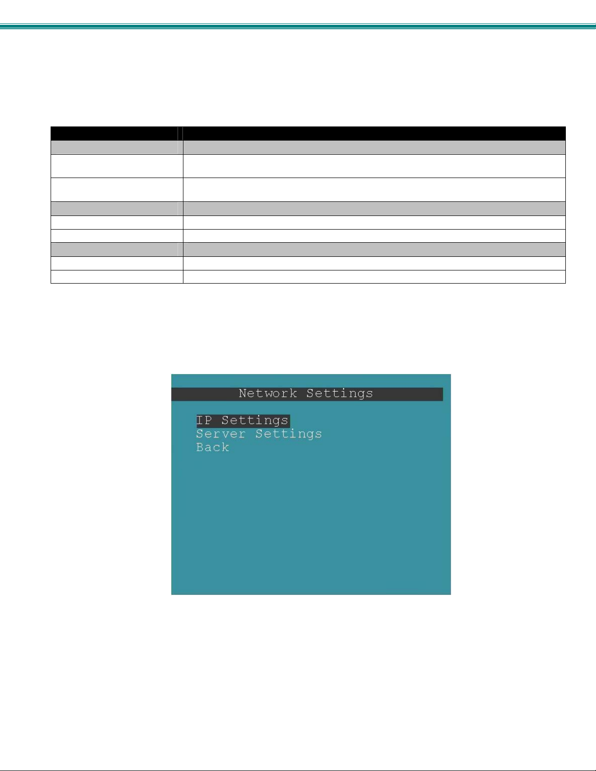
SPLITMUX Quad Screen 4K Multiviewer
System Settings Description
Unit Settings
Name Unique name for this SPLITMUX to appear on the web interface login page and header of each
Keypad Pin PIN number that must be entered before OSD mode can be accessed to change settings- 4
Serial Port Settings
Baud Rate Baud rate for RS232 commands- select a value between 1200 and 115200 bps
Serial Address Serial Address for RS232 commands and for the IR Remote- select value from 1-15
OSD Screen Settings
Horiz Offset Position OSD Horizontal Offset from left (0-70%) Use Arrow Buttons to move
Vert Offset Position OSD Horizontal Offset from top (0-70%) Use Arrow Buttons to move
web interface page
digits using buttons 1-4. 0000 (default) = No PIN required
Network Configuration
The Network Configuration screen is where all network settings are entered. These settings determine how you will remotely
access the SPLITMUX. Choose between your basic network (IPv4) settings and several miscellaneous server settings.
Figure 61- OSD Network Configuration
57
Page 64
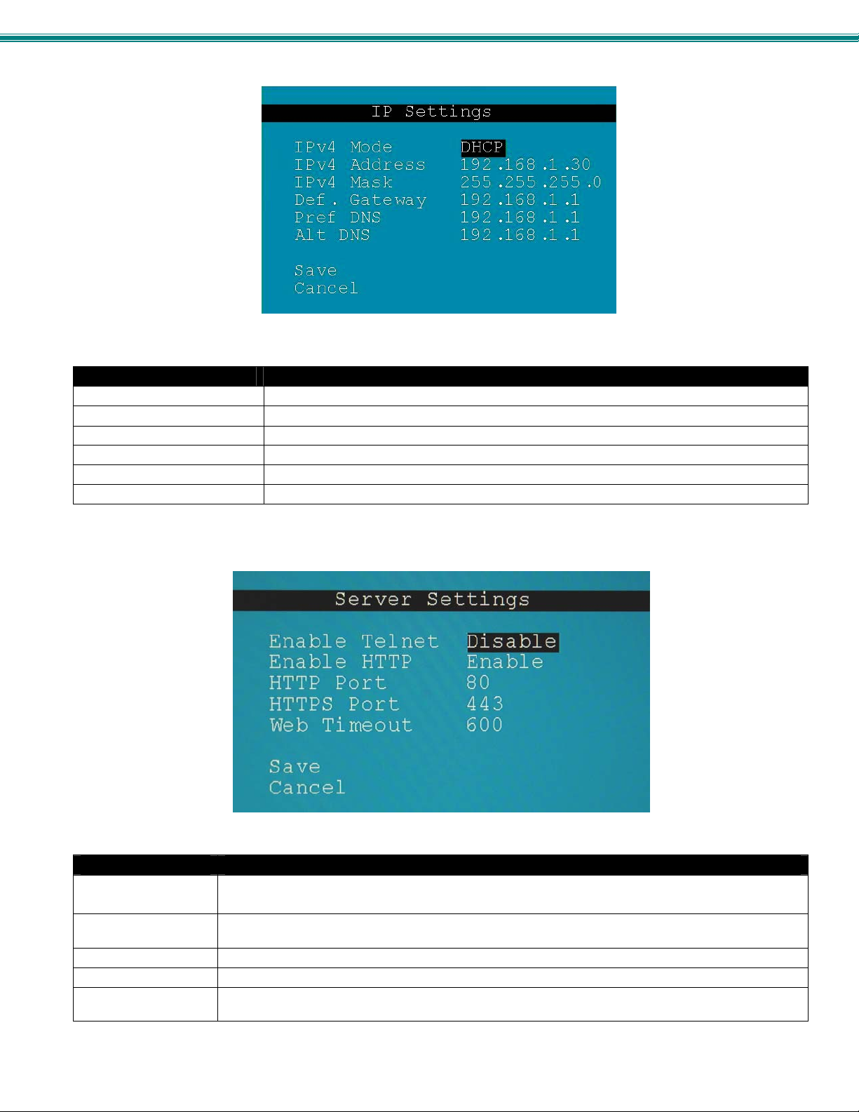
SPLITMUX Quad Screen 4K Multiviewer
The IP address shown here
is only used when the IPv4
mode is set to “STATIC”.
To view the IP address when
the mode is set to “DHCP”,
go to the “System Information”
page (page 65).
Figure 62- OSD IP Settings
IP Settings
Mode Select the method for acquiring IP Settings- Static (manual), DHCP (automatic) or Disable
IP Address
Subnet Mask Enter valid subnet mask (for Static Mode)
Default Gateway Enter valid default gateway (for Static Mode)
Primary DNS Address Enter preferred name server (for Static Mode)
Alternate DNS Address Enter alternate name server (for Static Mode)
Note: If you select “DHCP” for the mode, make sure a DHCP server is running on the network the SPLITMUX is
connected to.
Enter valid IPv4 address (for Static Mode) (default is 192.168.1.30)
Figure 63- OSD Server Settings
Server Settings
Enable Telnet Change to “Enable” to permit access to the SPLITMUX via Telnet
The default is disabled.
Enable HTTP Change to “Enable” to allow access to the SPLITMUX via standard (non-secure) HTTP requests
The default is disabled.
HTTP Port Port to be used for standard HTTP requests (default is 80)
HTTPS Port Port to be used for HTTPS requests (default is 443)
Web Timeout Number of minutes after which idle web users will be logged-out (maximum is 32000, enter 0 to disable
this feature)
58
Page 65
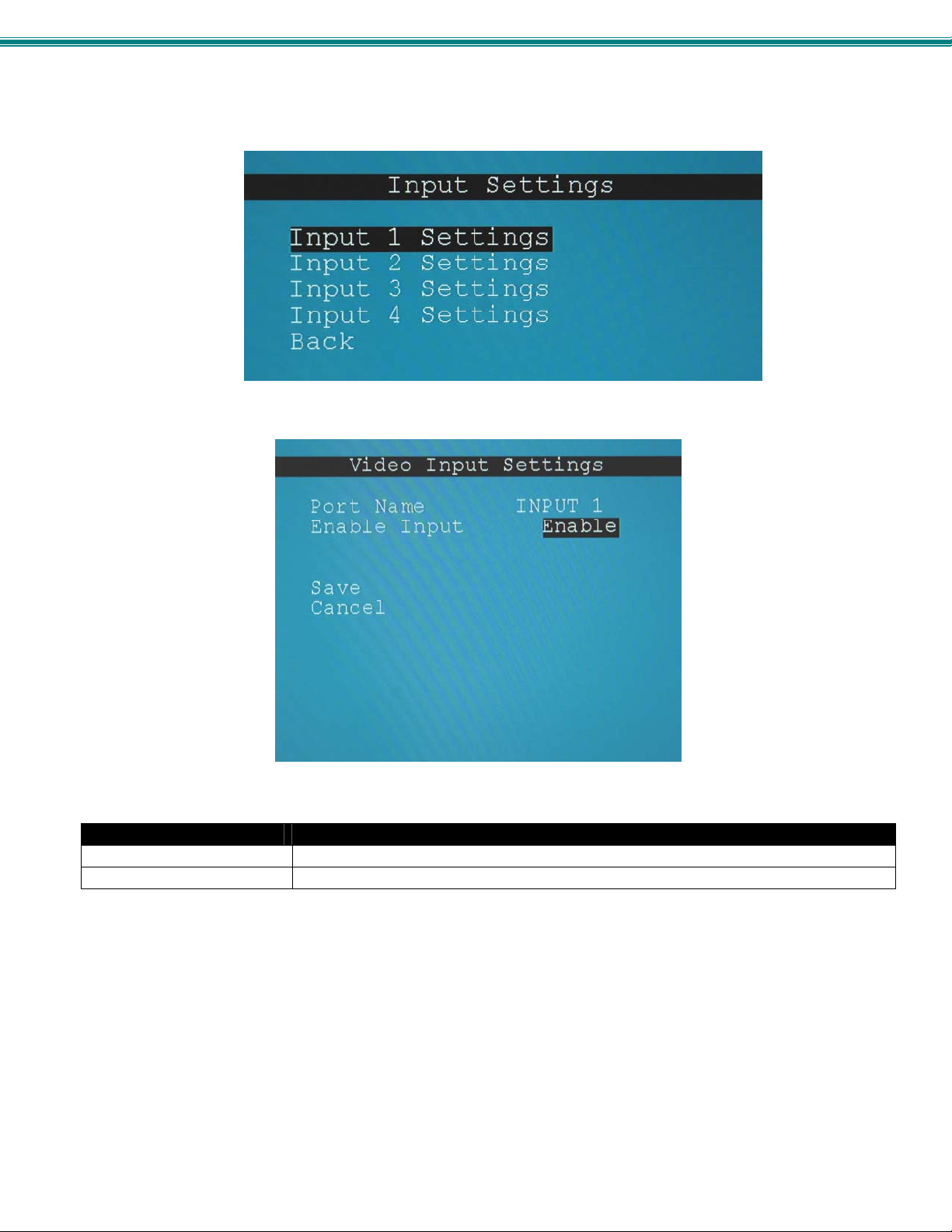
SPLITMUX Quad Screen 4K Multiviewer
Input Configuration
Configure what inputs will be viewed and heard on the display and what EDID mode they should be in from the Input
Configuration screen. Select which input to configure and choose the settings to be applied.
Figure 64- OSD Input Configuration
Figure 65- OSD Input Settings
Input Settings
Input Channel x Port Name Enter a port name to associate with the video source on Input 1
Enable Choose to Enable or Disable the video input for this channel
Each Input channel can be configured with these settings.
59
Page 66
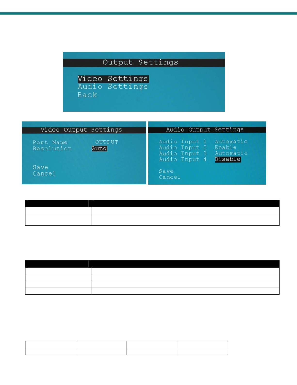
SPLITMUX Quad Screen 4K Multiviewer
Output Configuration
The Output Configuration determines how the inputs will be viewed on the display. From this menu you can also sel ect the Audio
Output Configuration which will provide settings for how the audio from the inputs is managed.
Figure 66- OSD Output Settings
Video Output Settings
Output Port Name Enter a port name to associate with the display (optional)
Output resolution Select the output resolution to send to the display (options shown below) or select Auto to
Note: PIP and Custom Screen Mode Settings will not be applicable when the output settings are set above 1920x1080p.
Note: When the Output resolution is set to “Auto”, your SPLITMUX will automatically sense the native resolution of your
monitor and set the output resolution to that when powering ON the SPLITMUX.
Audio Output Settings
Input 1 Audio Mode Select the audio mode for the Input- between enabled/disabled/automatic
Input 2 Audio Mode Select the audio mode for the Input- between enabled/disabled/automatic
Input 3 Audio Mode Select the audio mode for the Input- between enabled/disabled/automatic
Input 4 Audio Mode Select the audio mode for the Input- between enabled/disabled/automatic
When Audio Mode is enabled, the audio will come through any time the input signal is present (whether the video is enabled or
not)
When Audio Mode is disabled, no audio will be heard from that input.
When Audio Mode is automatic, the audio will only be heard from that input if that input is the currently selected input. To avoid
confusion from multiple audio inputs when using Quad or PIP modes, set each audio input to automatic.
Video Output Resolutions to choose from (progressive scan):
1280x720@60Hz 2048x1080@60Hz 3840x2160@60Hz 4096x2160@30Hz
1920x1080@60Hz 3840x2160@30Hz 4096x2160@60Hz
have it choose from the EDID table.
60
Page 67
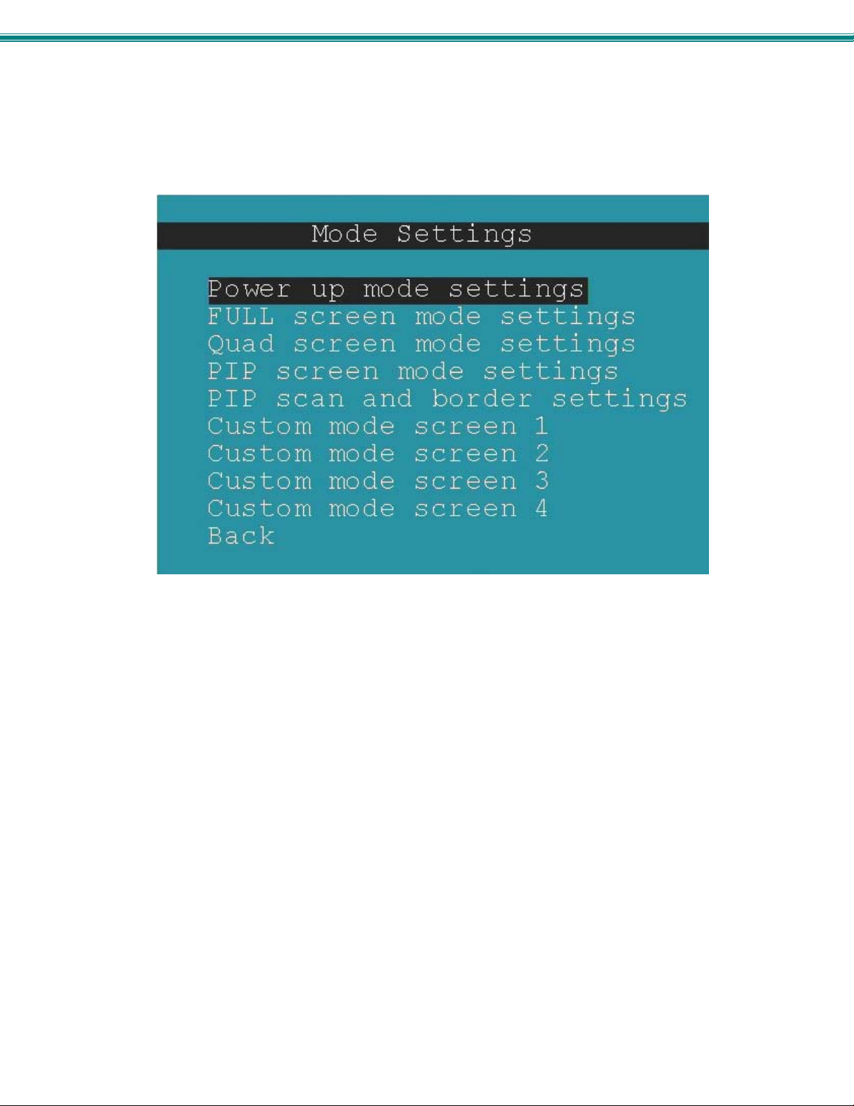
SPLITMUX Quad Screen 4K Multiviewer
Mode Configuration
Mode Configuration will determine how each display mode provided by the SPLITMUX will be presented. Mode characteristics
will determine how the images will look on the display.
Figure 67- OSD Mode Settings
61
Page 68
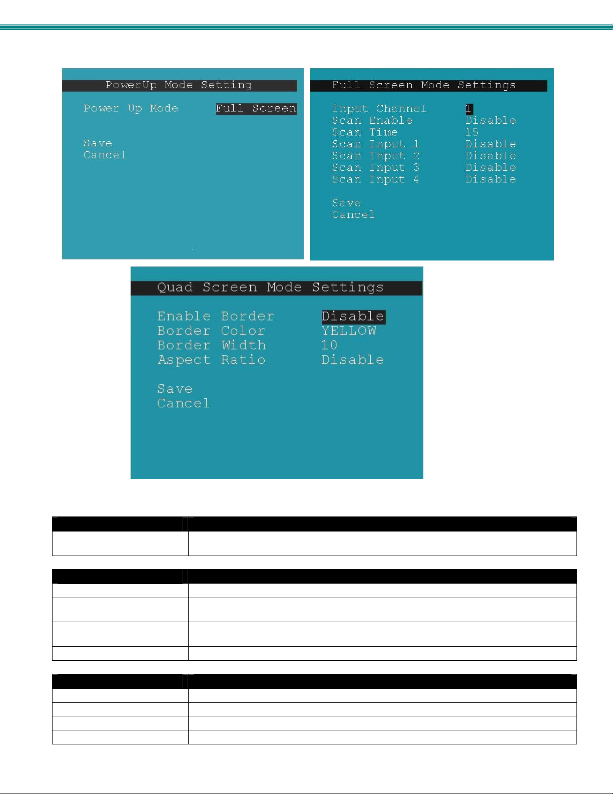
SPLITMUX Quad Screen 4K Multiviewer
Figure 68- Default, Full Screen and Quad Screen Settings
Power Up Mode Setting
Power Up Mode Choose the default mode the SPLITMUX will be in when powered ON. Choose from Full
Full Screen Mode Settings
Input Channel Select the input channel assigned to Full Screen
Enable Scan Enable scanning for the full screen input channel- to automatically switch from one channel to
Scan time Set the dwell time while scanning- the amount of time (in seconds) each channel will appear
Scan input 1-4 Select Enable or Disable to include input 1, 2, 3 or 4 in the scanning sequence
Quad Screen Mode Settings
Enable Border Choose whether or not to place a border around each input displayed
Border Color Choose the color of the border around each input
Border Width Choose the width of the border around each input (0-50 pixels)
Aspect Ratio Choose whether or not to maintain the aspect ratio for each displayed image
Note: Quad Screen Mode border settings will not be applicable when the output settings are set above 1920x1 080p.
screen , PiP screen, Quad screen or Custom screen
another
at full screen- range is 0-999
62
Page 69
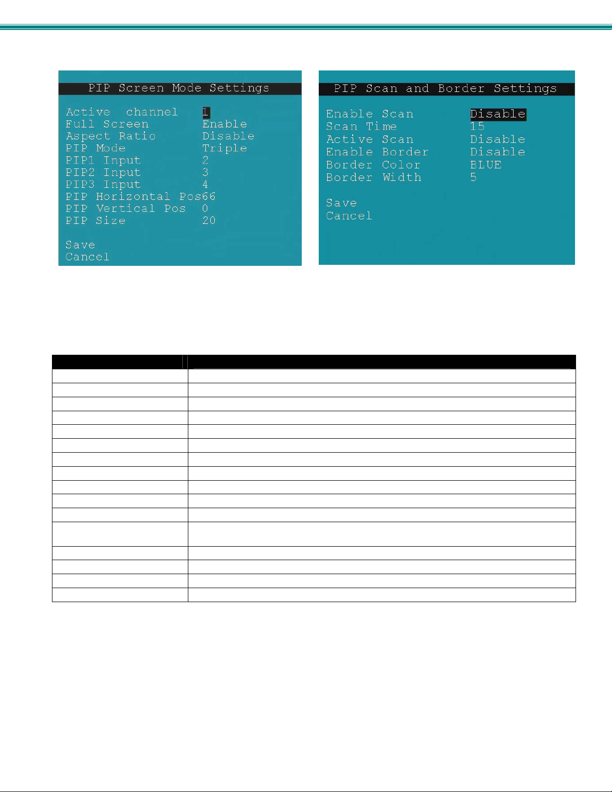
SPLITMUX Quad Screen 4K Multiviewer
Figure 69- PIP Screen Mode settings
Pip Screen Mode Settings
Active Channel Select which active channel is in full screen mode
Enable full screen Enable/disable active input in full screen mode with overlay
Enable aspect ratio Enable/disable the aspect ratio to be maintained for all displayed images
PIP Mode Select how many PIP images will b e displayed, 2, 3 or 4 (one will be at full screen)
PIP 1 Input Select which input channel will be in PIP up per right position
PIP 2 Input Select which input channel will be in PIP center position
PIP 3 Input Select which input channel will be in PIP low er right position
PIP Horizontal Position Position of PIP images from the right side of the screen- range is 0-90% of screen width
PIP Vertical Position Position of uppermost PIP from the top of the screen- range is 0-60% of screen height
PIP Size Size of the PIP image- range is 10-50%
Enable Scan Enable input channel scanning when PIP Mode is set to “Single”
Scan Time Set the dwell time while scanning- the amount of time (in seconds) each channel will appear in
Active Scan Enable/disable full screen scanning between the inputs while in PIP mode
Enable Border Place a border around each input displayed
Border Color Choose the color of the border around each input
Border Width Choose the width of the border around each input- from 0-50 pixels
the single PIP position- range is 0-999
Note: Custom and PIP Screen Mode will not support resolution above 1920x1080p. If reso lution is set above 1080p, the
SPLITMUX will only output 1080p resolution while in PIP or Custom modes.
63
Page 70
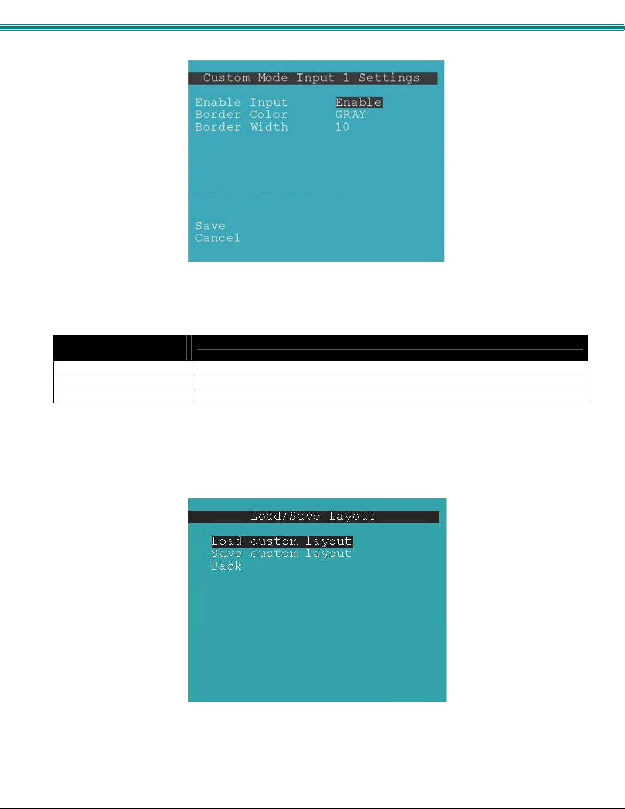
SPLITMUX Quad Screen 4K Multiviewer
Figure 70- OSD- Custom Screen Mode Settings
Custom Screen Mode
Settings Input x (1-4)
Enable Input Enable/disable displayin g the content of the input
Border color for Input Choose the color of the border aroun d the input
Border width for Input Choose the width of the border around the input (0-50 pixels) (0 = no border)
Load / Save Layout
When you have a screen layout configured in such a way that you want to save that layout for future viewing, select Load / Save
Layout to open the Save Layout menu.
Figure 71- OSD- Load/Save Layout functions
64
Page 71
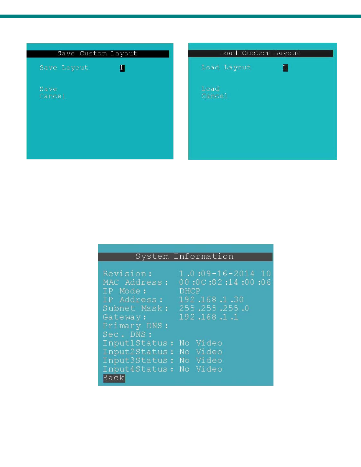
SPLITMUX Quad Screen 4K Multiviewer
Figure 72- Save or Load a Custom Layout
Up to 10 custom layouts can be saved and re-loaded as needed.
System Information
Select System Information from the main menu to view the current network settings, MAC address, and port status.
This is particularly
helpful when the
SPLITMUX is in DHCP
mode with a serverassigned IP address.
Figure 73- OSD- System Information Page
65
Page 72

SPLITMUX Quad Screen 4K Multiviewer
INFRARED REMOTE CONTROL
The IRT-UNV Infrared Remote Control provides the user with limited remote control of up to 15 NT I SPLITMUX-4K-4RT switches.
The IRT-UNV can control connections and change the operating modes without having to press buttons on the SPLITMUX case.
Note: The IRT-UNV will have no control over OSD menus.
Materials
Materials supplied with the IRT-UNV
NTI IRT-UNV Infrared Remote Control
2- AAA Batteries (installed)
:
Buttons
The IRT-UNV Infrared Remote Control user interface consists of a keypad with
29 buttons. Fourteen of those buttons are used for the SPLITMUX
and have the following functions:
Numerical Values (1-4)
Selects port numbers (for IN)
Select mode to switch to
IN
Pressed to indicate an input port selection
OUT
Pressed to initiate change of mode
SYS
Pressed to select the desired SPLITMUX to be controlled
Only used when controlling multiple systems
Must be followed by a system number: 1-15
ENTER
Press to have command take immediate effect
Press to complete command when SYS is used
SAVE
Pressed to save a configuration of channels as viewed on the display
RECALL
Pressed to recall and restore a configuration of channels previously
viewed on the display
AUDIO
Press to select which input the audio controls will effect
VOL + / -
Press to increase/decrease audio levels from selected input
MUTE Audio
Press to toggle audio on/off from selected input
66
Page 73

SPLITMUX Quad Screen 4K Multiviewer
Operation
Operation of the IRT-UNV is intuitive. The number of button presses required to complete any operation is kept to a
minimum. This is accomplished using intelligent software within the NTI SPLITMUX. As a button is pressed, the PWR/ST ANDY
green LED on the SPLITMUX will flash red to indicate it has received the signa l (whether that signal is valid to cause a chan ge or
not).
Changing Ports
To change the Active input port (FULL screen mode),
press <IN>, then the port number (1-4).
To change modes,
For Full Screen Mode press <OUT>, then <1>
For Quad Screen Mode press <OUT>, then <2>
For PIP Screen Mode press <OUT>, then <3>
For Custom Screen Mode press <OUT>, then <4>
To have any command take immediate effect, end it by pressing <ENTER>. (Example- press <IN> then <1> then
<ENTER> to change to Active input port 1) Otherwise, there will be a 2 second delay for it to take effect.
When changing the Active input port, the audio from that
input port will also be heard provided the audio mode for the
input is set to "Automatic" and no other audio mode for an
input port is set to "Enable". See pages 23 or 61 for more.
Audio Control
Toggling Mute On/Off: Press <Audio>, then the port number (1-4), then <Mute>
Changing Audio Gain (Volume): Press <Audio>, then the port number (1-4), then Vol+ / Vol- (can be pressed once or
many times)
Save and Recall
To save a configuration of channels on the display using the IR Remote control, the <Save> and <Recall> buttons are provided.
Up to 10 configurations can be saved and recalled. Once the display has the configuration you want to be able to quickly return
to, press the <Save> button followed by two digits (01-10). To recall a configuration at any time, press the <Recall> button
followed by the associated two digit number.
Multiple Switch Control
All NTI SPLITMUX-4K-4RT will work with the same IRT-UNV IR Remote control. As a result, a user with multiple NTI
SPLITMUXs may find that, if the switches are installed too close together, both switches may respond to an IR command intended
only for one switch. Also, the user may want to control multiple s witches with a single remote, instead of having one remote per
switch. To control more than one SPLITMUX from one R emote, the IRT -UNV IR Remote provides the “S YS” button, which can be
used to select the specific NTI switch to be controlled.
All switches will have the capability to allow the user to set the switch address (1-15) (see page 1 8, 42 or 56 ). The default
switch address is 1. Each switch to be separately controlled must be set to a different address prior to using the Remote Control.
With the addresses set;
1. press the <SYS> button on the IRT-UNV,
2. followed by a single (i.e. <1>) or two digit number (i.e. <0> then <1>) corresponding to the address of the switch to be
controlled,
3. followed by <ENTER>.
Upon accepting the SYS command, the switch with the corresponding address will illum inate the “IR” L ED in gree n for visual
indication and respond to all IR Remote commands. All other units will illuminate in red and ignore any further commands.
Note: To prepare to send a command to all SPLITMUXs at the same time (all SPLITMUXs would have to b e within
line-of-sight of the IRT-UNV), press <SYS> then <0> then <ENTER>. Pressing <0> tells the Remote to send the
command to all addresses. The PWR/STANDY LED on each SPLITMUX will illuminate and remain green to indicate
readiness to receive commands.
67
Page 74
SPLITMUX Quad Screen 4K Multiviewer
Technical Specifications For IRT-UNV
Number of Controllable Systems Max: 15
Pushbutton Control 29 keys
Power supply 2x AAA Battery
Chassis material Plastic
Approvals RoHS
Troubleshooting the IRT-UNV
PROBLEM SOLUTION
IRT-UNV is not selecting inputs
or changing modes
Check battery
The IRT-UNV may be configured to control the wrong switch- see “Multiple
Switch Control” above.
68
Page 75
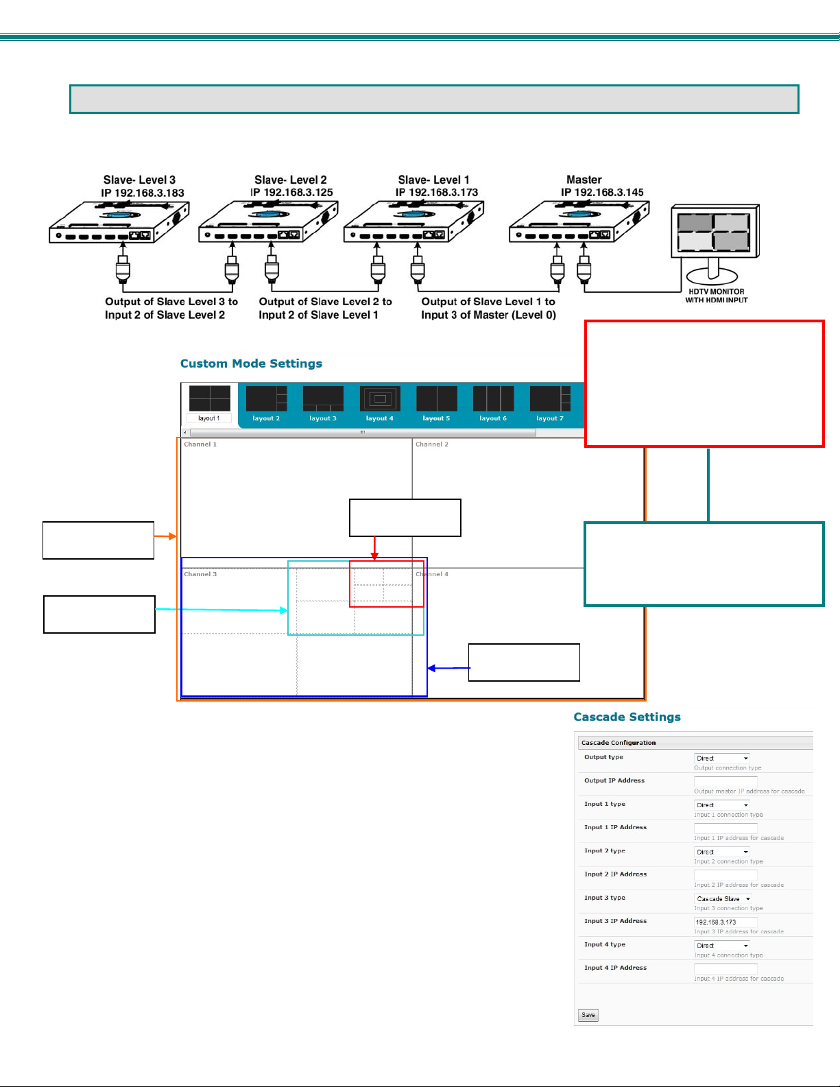
SPLITMUX Quad Screen 4K Multiviewer
EXAMPLE OF CASCADED CONFIGURATION
In the example below, 4 SPLITMUXs are connected in a cascaded configuration.
IP
IP
Figure 74- View of cascaded configuration from Master
The Custom Mode Settings page provides a view of the combined custom mode
settings of the configuration. Dotted lines indicate input layouts of slave units
connected. In order to make edits to the configuration of slave units, either change
the IP address in the URL bar or double-click on the channel where slave units are
indicated.
In Cascade Settings (image right), the slave connected to Input 3 is indicated. All other
connections are direct, including the Output since on this SPLITMUX the output is
connected to the display.
In this case, double-click on channel 3 to switch to the configuration of the SPLITMUX
at IP 192.168.3.173.
IP
IP
Note: When cascading SPLITMUXs,
make sure the Output Settings of all
slaves are set at or below
1920x1080p. The Input of the
Master does not support higher
resolution settings from the slave
units.
To reduce cost, we recommend
using the SPLITMUX-HD-4RT for any
units connected as Slaves in a
cascaded configuration.
69
Page 76
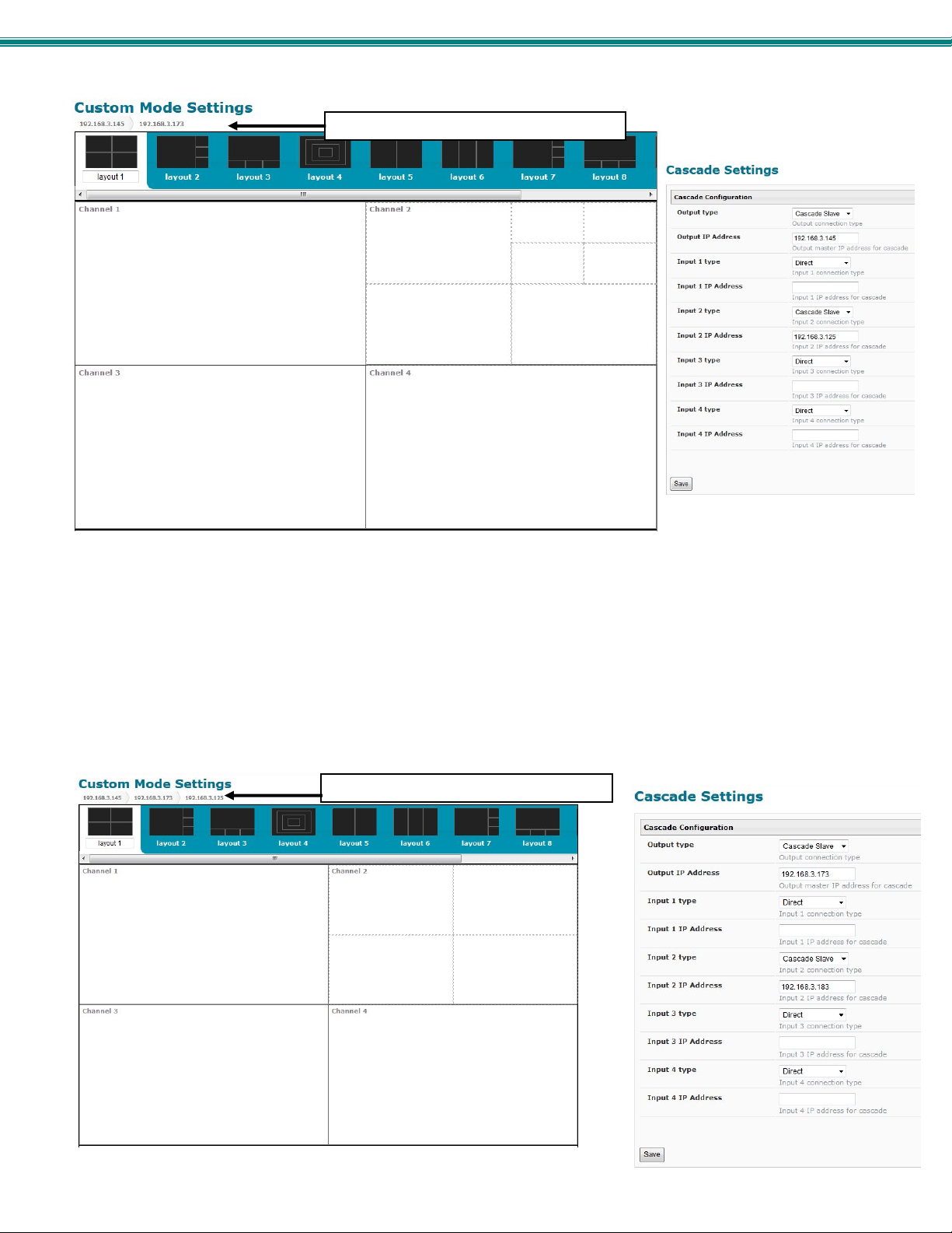
SPLITMUX Quad Screen 4K Multiviewer
tabs showing hierarchy of configuration
Figure 75- View of cascaded configuration from Slave at IP 192.168.3.173
When looking at a slave unit, the hierarchy will be indicated at the upper left of the layout choices. The leftmost tab is the master,
followed by the nearest connected slave. In Figure 73, it is indicated that two levels of SPLITMUXs are connected through
channel 2 (Input 2). These are, of course, IP 192.168.3.125 and IP 192.168.3. 183.
Any edits made using the web interface configuration menu at this level will directly and only impact the SPLITMUX at IP
192.168.3.173.
To switch back to the configuration of the master, click on the tab labeled “192.168.3.145”.
To switch to the next slave in the configuration (IP 192.168.3.125), double-click on channel 2.
tabs showing hierarchy of configuration
Figure 76- View of cascade configuration from Slave at IP 192.168.3.125
70
Page 77
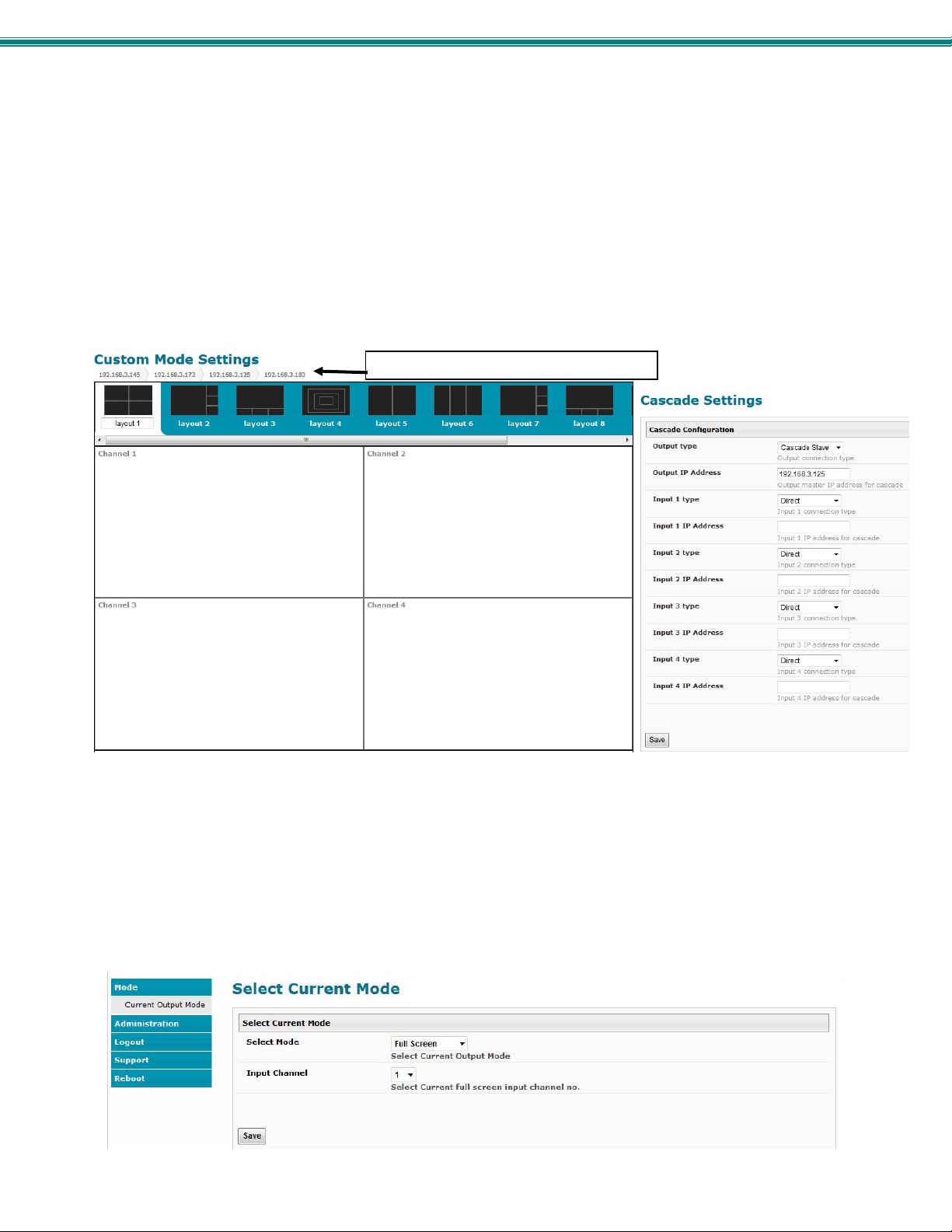
SPLITMUX Quad Screen 4K Multiviewer
In Figure 77, it is indicated that one level of SPLITMUX is connected through channel 2 (Input 2). This is IP 192.168.3.183.
Notice that in Cascade Settings the slave (192.168.3.183) is configured for connection to Input 2, and the upstream slave
(192.168.3.173) is connected to the output. Other input ports are configured for direct connection to input sources.
Any edits made using the web interface configuration menu at this level will directly and only impact the SPLITMUX at IP
192.168.3.125.
To switch to the last slave in that configuration (IP 192.168.3.183), double-click on channel 2.
To switch back to the configuration of the master or upper level slave, click on the appropriate tab.
tabs showing hierarchy of configuration
Figure 77- View of custom configuration of Slave at IP 192.168.3.183
In Figure 78, we see that there are no slaves connected to this SPLITMUX. In Cascade Settings, only the output master IP
address is configured.
At each configuration level, the Current Mode setting will dictate what is viewed upstream at the output, regardless of how the
custom layout is configured. The custom layout will only impact what is viewed if the Current Mode is set to “Custom” (page 17).
The audio is impacted in the same fashion. If the audio from an input on the lowest-level slave is desired, the configured in put
channel for each higher level slave must be set to pass that audio signal, all the way through to the master.
Figure 78- Current output mode selection
71
Page 78
SPLITMUX Quad Screen 4K Multiviewer
SPECIFICATIONS
Video Signal Supported HDMI and DVI
Input Resolution supported 1080p, 2048x1080@ 60Hz, 1920x1200 @ 60Hz
Output Resolution supported Up to UHD(2160p), 4096 x 2160 @ 60Hz
HDMI supported- Inputs 24,30 and 36 bit, xvYCC, YCbCr
HDMI supported- Output 24 and 30 bit sRGB
Audio supported 4-channel mixing stereo with 16,20 or 24 bit uncompressed PCM audio
Input Bandwidth 165 MHz (2.25 Gbps)
Output Bandwidth 594 MHz (5.94 Gbps)
HDCP Compliant- V1.2 (on Inputs) and V1.4\2.2 (on Outputs)
Platforms supported Windows 2000/XP/Vista/7/8, Windows Server 2000/2003/2008, Solaris, Linux, FreeBSD, and
MAC OS 9/10.
Ports (SPLITMUX-4K-4RT) 1- HDMI output
4- HDMI inputs
1- RJ45 Ethernet
1- RJ45 RS232
1- 2.1mm x 5.5mm power jack
2- USB Keyboard/Mouse
Additional Ports
(SPLITMUX-USB4K-4RT
only)
Protocols supported HTTP, HTTPS, TCP/IP, DHCP, UDP, ARP, IPV4
Operating temperature 32 to 122°F (0 to 50°C).
Storage temperature -22 to 140°F (-30 to 60°C).
Operating and storage relative
humidity
Power
SPLITMUX-4K-4RT
SPLUTMUX-USB4K-4RT
Power consumption 20W
Dimensions WxDxH (in)
SPLITMUX-4K-4RT
SPLITMUX-4K-4RT-(2)R w/o
rackmount kit
SPLITMUX-4K-4RT-(2)R w/
rackmount kit
SPLITMUX-USB4K-4RT
SPLITMUX-USB4K-4RT-(2)R
w/o rackmount kit
SPLITMUX-USB4K-4RT-(2)R
w/rackmount kit
Case material powder coated steel
Regulatory approvals CE, RoHS
2- USB 2.0 High Speed Transparent
17 to 90% non-condensing RH.
120VAC or 240VAC at 50 or 60Hz-5VDC/6A AC Adapter
120VAC or 240VAC at 50 or 60Hz-9VDC/8A AC Adapter
7.35x4.98x1.09 (187x126x28 mm)
7.35x4.98x1.75 (187x126x45 mm)
19x4.98x1.75 (483x126x45 mm) (excludes cable tray)
(cable management tray adds 3.37” to depth)
72
Page 79
SPLITMUX Quad Screen 4K Multiviewer
TROUBLESHOOTING
Each and every piece of every product produced by Network Technologies Inc is 100% tested to exacting specifications. W e
make every effort to insure trouble-free installation and operation of our products. If problems are experienced w hile installing this
product, please look over the troubleshooting chart below to see if perhaps we can answer any questions that arise. If the
answer is not found in the chart, a solution may be found in the knowledgebase on our website at
http://information.networktechinc.com/jive/kbindex.jspa
& Canada or 1-330-562-7070 worldwide. We will be happy to assist in any way we can.
Problem Cause Solution
Image on monitor is blurry,
has wavy lines, colors are
off, or just is not very good
on all ports; all modes
Cannot log in to SPLITMUX
via Ethernet
Cannot connect to
SPLITMUX via Telnet
No Audio The audio may be disabled or the
Cannot get an image on the
display
Image poor coming from
input port X (1-4)
Resolution of Output Setting is not
supported by the monitor.
Poor quality output cable
Poor cable connection
Incorrect IP address has been
entered in the browser
User is on a different subnet
Settings are not correct
User is on different subnet
channel with the audio has not been
selected
The display does not support the
selected output resolution
There may be a sync issue
Poor cable or poor connection
or contact us directly for help at 1-800-742-8324 (800-RGB-TECH) in US
Check the Output Resolution setting (page 23) against
the specifications for the connected display.
Try a different output cable
Try to hot plug cable at the SPLITMUX and at the display
Check the System Information page from the front panel
LCD display for the assigned IP Address
Make sure user is on same subnet as the SPLITMUX
Enable Telnet using the Web Interface (Network Settings
page
Make sure you are entering the correct IP Address
(check System Information page)
Make sure you connect via port 2000 (the default port for
Telnet is 23 but this will not work)
Make sure you are trying to connect from the same
subnet the SPLITMUX is on
Make sure audio has been enabled and the channel from
which audio is desired has been selected
Check the Output Resolution setting (page 23) against
the specifications for the connected display.
Hot plug the output cable to the display
Try a different cable
Hot plug the cable at the SPLITMUX and at the source
as needed
INDEX
baud rate, 36
cascade settings, 30
connections, 8
custom settings, 26
default IP address, 16
Device Discovery Tool, 15
downloads, 35
Ethernet, 10
firmware update-web, 33
IRT-UNV, 66
Java Runtime Environment, 15
load layout, 29, 53, 64
log in, 16
mounting, 4
network settings, 20
OSD menus, 55
output settings, 22
Password, 16
RS232 pinout, 36
save layout, 29, 53, 64
serial settings, 18
system information, 34
Telnet, 38
terminal, 10
text menu, 39
username and password, 16
users, 32, 45
web browsers supported, 2
MAN240 REV 5/6/19
73
 Loading...