

Page 1
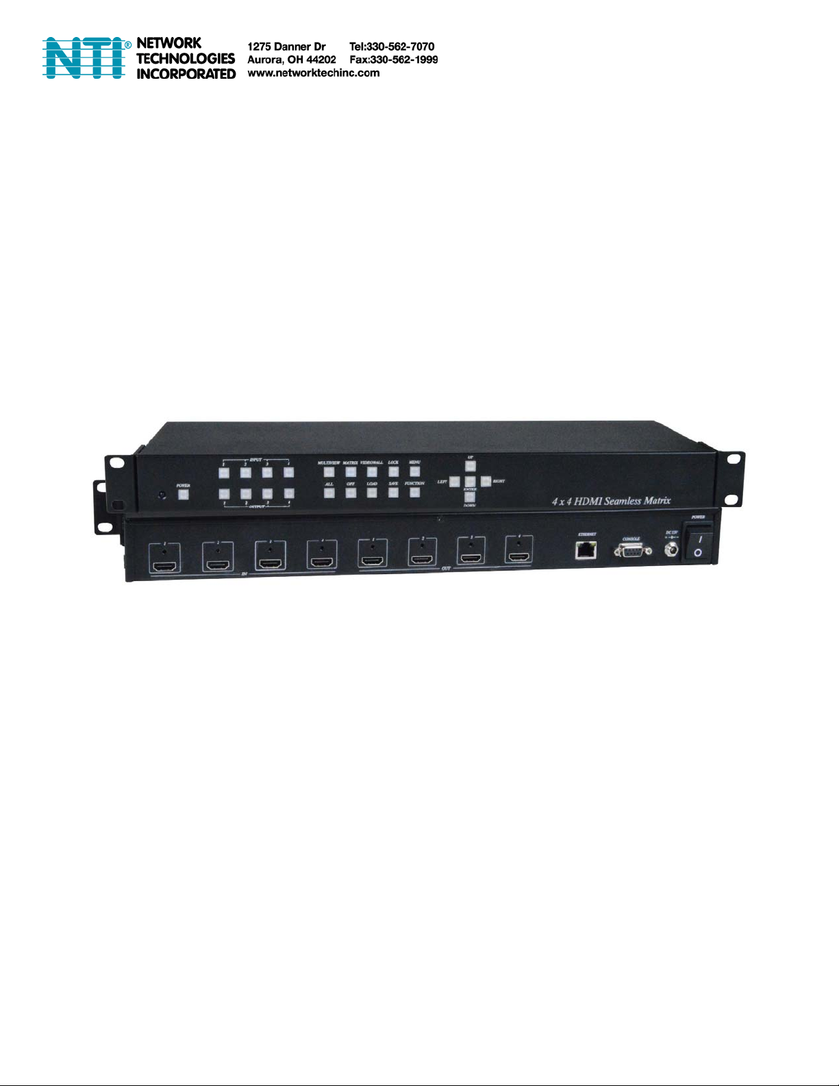
SPLITMUX-4X4-HDVWC
4x4 HDMI Multiviewer / Video Matrix Switch / Video Wall Processor
Installation and Operation Manual
MAN307 3/5
/18
Page 2
4x4 HDMI Multiviewer/Video Matrix Switch/Video Wall Processor
This SPLITMUX-4X4-HDVWC is the perfect solution for displaying content from up to four sources
on four HDTV displays. Each of the sources can be individually scaled. Seamless switching ensures
no frame loss during picture transitions. Eight preset buttons allow the user to store and recall
custom-configured routing presets. Build in OSD menu simplifies system configuration. The HM44
HDMI Seamless Matrix is a great solution for small and large commercial venues that require content
from four sources displayed on four displays instantly and without any loss of picture.
Features:
Input and Output resolutions up to 1080p Full HD and 1920x1200 (WUXGA)
Support LPCM7.1 @ 192KHz, Dolby True HD, DTS-HD MA
HDMI1.3, DVI1.0, and HDCP 1.4 compliant
Video-Wall mode supports 2 x 2 Video-Wall with 4 selectable input sources
Support 4 input and 4 multiview windows seamless switching
Multiview mode support scales and sizes each picture.
Multiview mode support PIP, POP and set PIP priority
Support panel button, IR remote, RS232, Web GUI and APP control
Support OSD menu setting
Field-upgradable firmware for both web server and RS232.
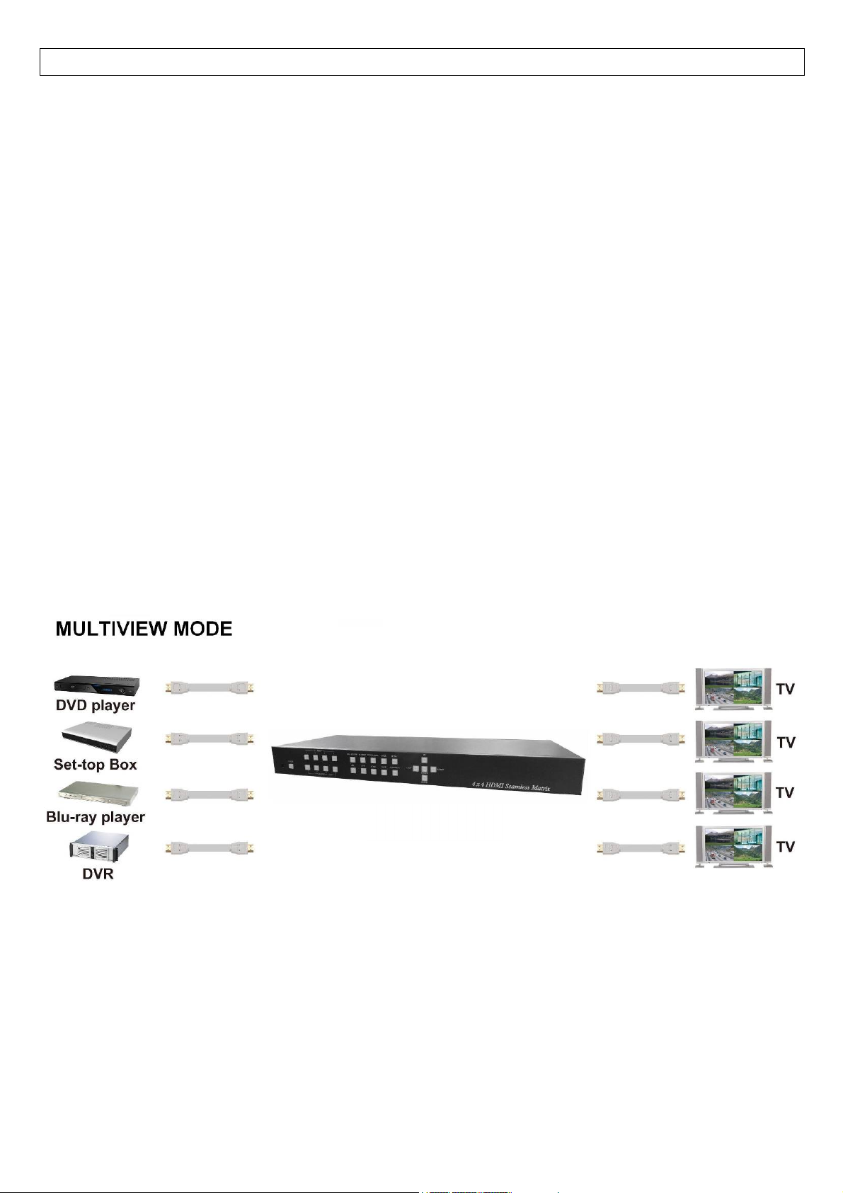
Application View:
1
Page 3
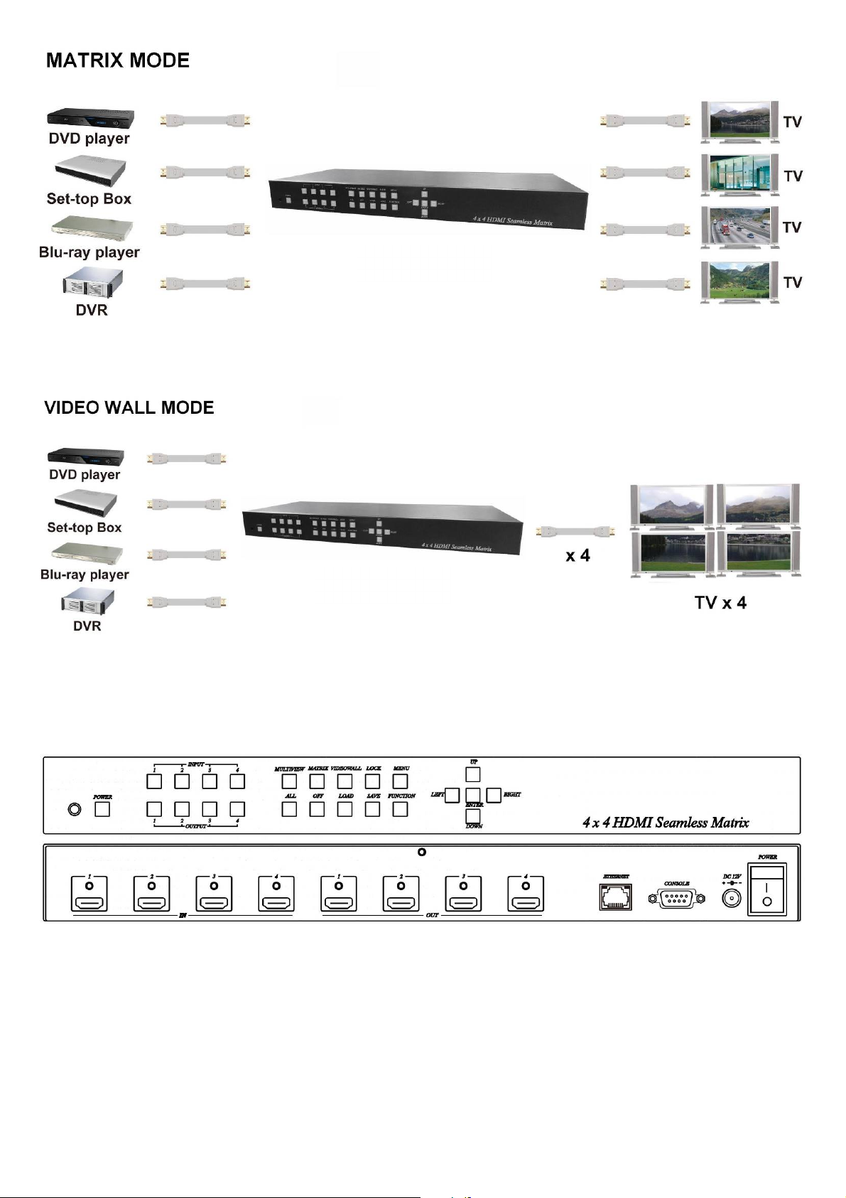
Panel View :
2
Page 4
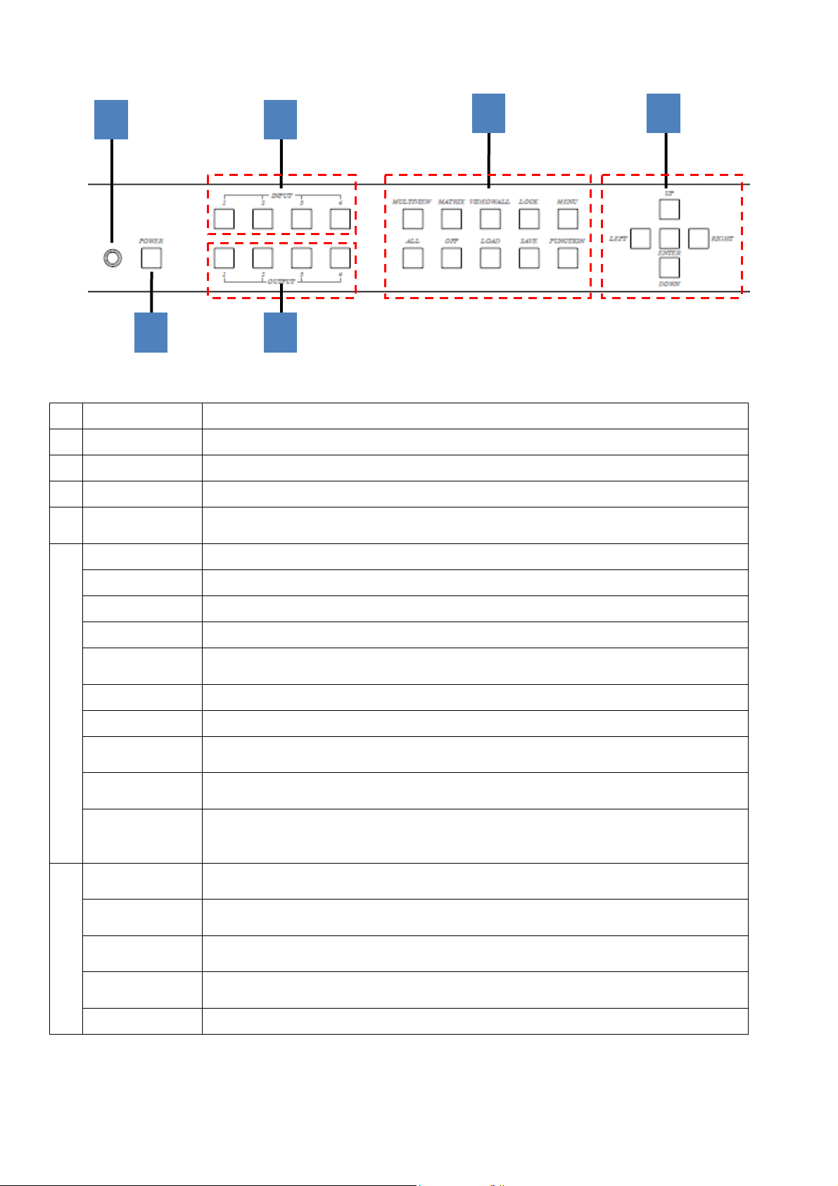
Front Panel Function:
1
2
3
4
Panel Button Function:
No. Function Name Description
1 IR
2 POWER Power on / standby
3 INPUT 1~4 Press these buttons to select the desired input
4 OUTPUT 1~4
MULTIVIEW
Receiving IR remote signal
Press these buttons to select the desired output (not available for videowall
mode)
Enter Multiview mode (All output display same screen)
5
6
MATRIX Enter Matrix mode
VIDEOWALL Enter videowall mode
LOCK
MENU
ALL Select all output (not available for videowall mode )
5
OFF Turn off the selected output (not available for videowall mode )
LOAD
SAVE
FUNCTION
UP
DOWN
6
LEFT
RIGHT
ENTER Execution selected function
Use this button to lock / unlock panel button and prevent accidental changes.
Enter OSD menu (only viewed at Monitor connected to Output 1)
Back to upper level of menu
Load layout/source in Multiview and Matrix mode from scene 1~8
Load screen position in VIDEOWALL mode from scene 1~4
Save current layout/source in Multiview and Matrix mode to scene 1~8
Save screen position in VIDEOWALL mode to scene 2~4
Switch different PIP/POP layout in Multiview Mode
Bezel correction (adjust screen position) in VIDEOWALL
Not available in MATRIX
Move menu function up in OSD
Move screen position up in videowall mode.
Move menu function down in OSD
Move screen position down in videowall mode.
Move menu function left in OSD
Move screen position left in videowall mode.
Move menu function right in OSD
Move screen position right in videowall mode.
MODE
MODE
3
Page 5

Operating:
Multiview mode:
Output/input selection:
1. Press OUTPUT 1~4 buttons to select the desired output windows (A~D), button LED will light on. You could select
multiple outputs at the same time.
2. Press INPUT 1~4 buttons to switch to desired input
3. Press ENTER to quit the input selection.
Window layout selection:
1. Press FUNCTION button to enter layout selection.
2. Press INPUT /OUTPUT 1~4 to select desired layout, total 8 sets.
3. Press ENTER to quit the layout selection.
Save scene:
1. Press SAVE button.
2. Press INPUT /OUTPUT 1~4 to save current windows layout and source of windows.
3. Press ENTER to confirm.
Load scene:
1. Press LOAD button.
2. Press INPUT /OUTPUT 1~4 to load saved layout/source.
3. Press ENTER to confirm.
Matrix mode:
Output/input selection:
1.
Press OUTPUT 1~4 buttons to select the desired output monitor, button LED will light on. You could select
UT at the same time.
OUTP
Press INPUT 1~4 buttons to switch to desired input
2.
3.
Press ENTER to quit the input selec
tion.
multiple
Save scene:
1.
Press SA
Press INPUT /OUTPUT 1~4 to save current sou
2.
Press ENTER to c
3.
Load sc
Press LOAD
1.
Press INPUT /OUTPUT 1~4 to load saved output/source, total 8 sets.
2.
3.
Press ENTER to c
VE button.
rce of output.
onfirm.
ene:
button.
onfirm.
Videowall mode:
Input selection:
1. Press INPUT 1~4 buttons to switch to desired input
Bezel correction:
1. Press FUNCTION button.
2. Press OUTPUT 1~4 to select the monitor to adjust screen position, shift depends on output resolution.
3. Press INPUT 1~4 to select the monitor to adjust screen position, shift depends on input resolution.
4. Press UP, DOWN, LEFT or RIGHT button to shift the screen.
5. Press ENTER to quit the position adjustment.
Save scene:
1. Press SAVE button.
2. Press INPUT 2~4 to save current position of each screen.
3. Press ENTER to confirm.
Load scene:
1. Press LOAD button.
2. Press INPUT 1~4 to load saved position of each screen(1 is factory default), total 4 sets.
3. Press ENTER to confirm.
4
Page 6
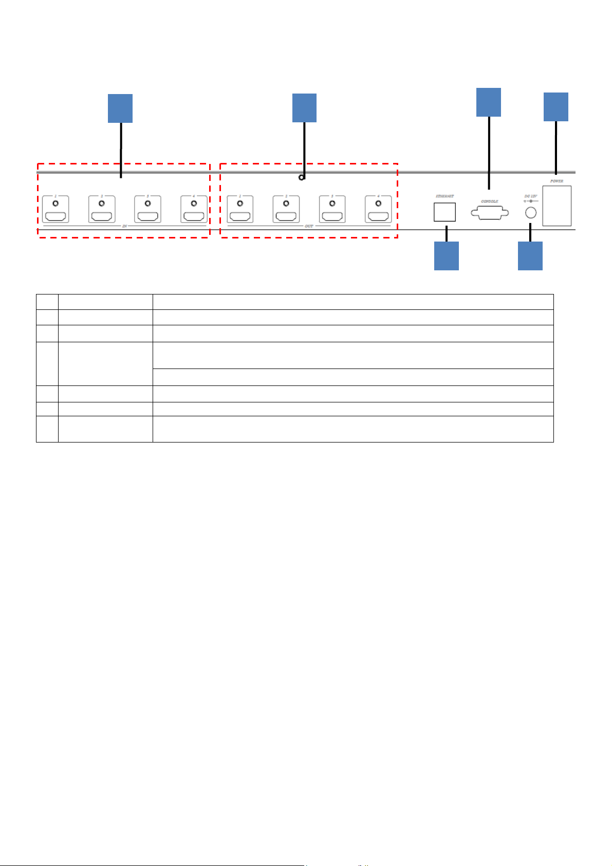
Rear Panel Function:
1
2
Panel Connector Function:
No. Name Description
1 INPUT 1~4 HDMI Input 1~4
2 OUTPUT 1~4 HDMI Output 1~4
Yellow LED: Link
3 ETHERNET
4 RS232 RS232 control / firmware update
5 DC12V External power supply
6 I/O
Green LED: Data transmit/receive
WebGUI control / Web firmware update
I: Power on
O: Power off
3
4
6
5
5
Page 7
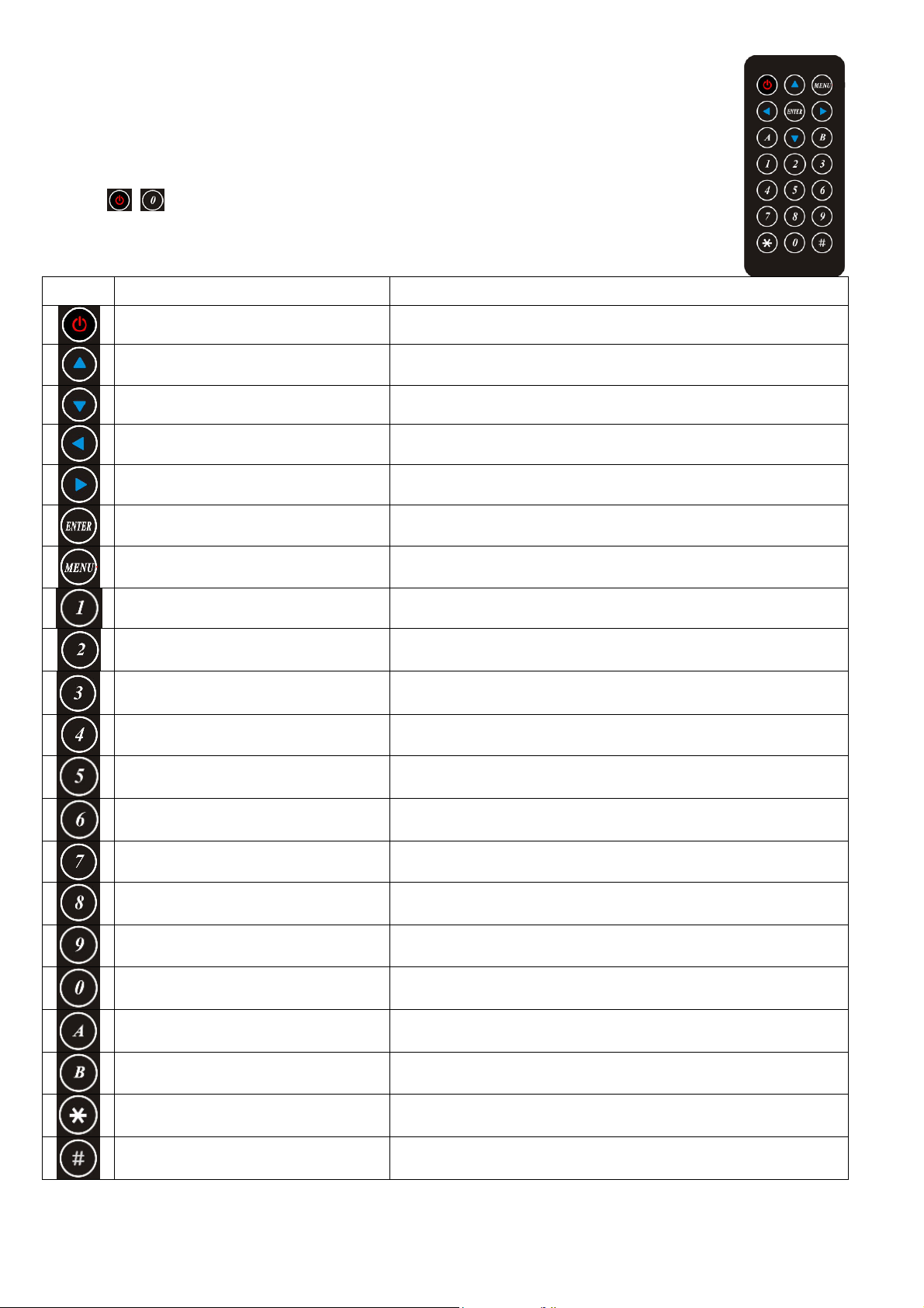
IR Remote Control (IR01) :
Initial at first time use the remote control or after change battery of remote control, the IR
remote control and the equipment IR Remote ID must be using same. The default IR
Remote ID is 0.
To setting the Remote ID, Press and hold power button, then press button 0 to complete the
setting.
+ .(for example)
Remote Control Button Function:
Symbol Function Name Description
POWER Power on / standby
UP Move menu function up in OSD
DOWN Move menu function down in OSD
LEFT Move menu function left in OSD
RIGHT Move menu function right in OSD
ENTER Execution selected function
Enter OSD menu (only viewed on Monitor at Output 1)
MENU
Quick output/input selection
Quick output/input selection
Quick output/input selection
Quick output/input selection
Back to upp
Press to select output 1
Switch to input 1 if output have been selected
Press to select output 2
Switch to input 2 if output have been selected
Press to select output 3
Switch to input 3 if output have been selected
Press to select output 4
Switch to input 4 if output have been selected
er level of menu
Reserved
Reserved
Multiview Switch to Multiview Mode
Matrix Switch to Matrix mode
Videowall Switch to Videowall mode
Turn off video Turn off video if output have been selected
Reserved
Reserved
Reserved
Reserved
6
Page 8
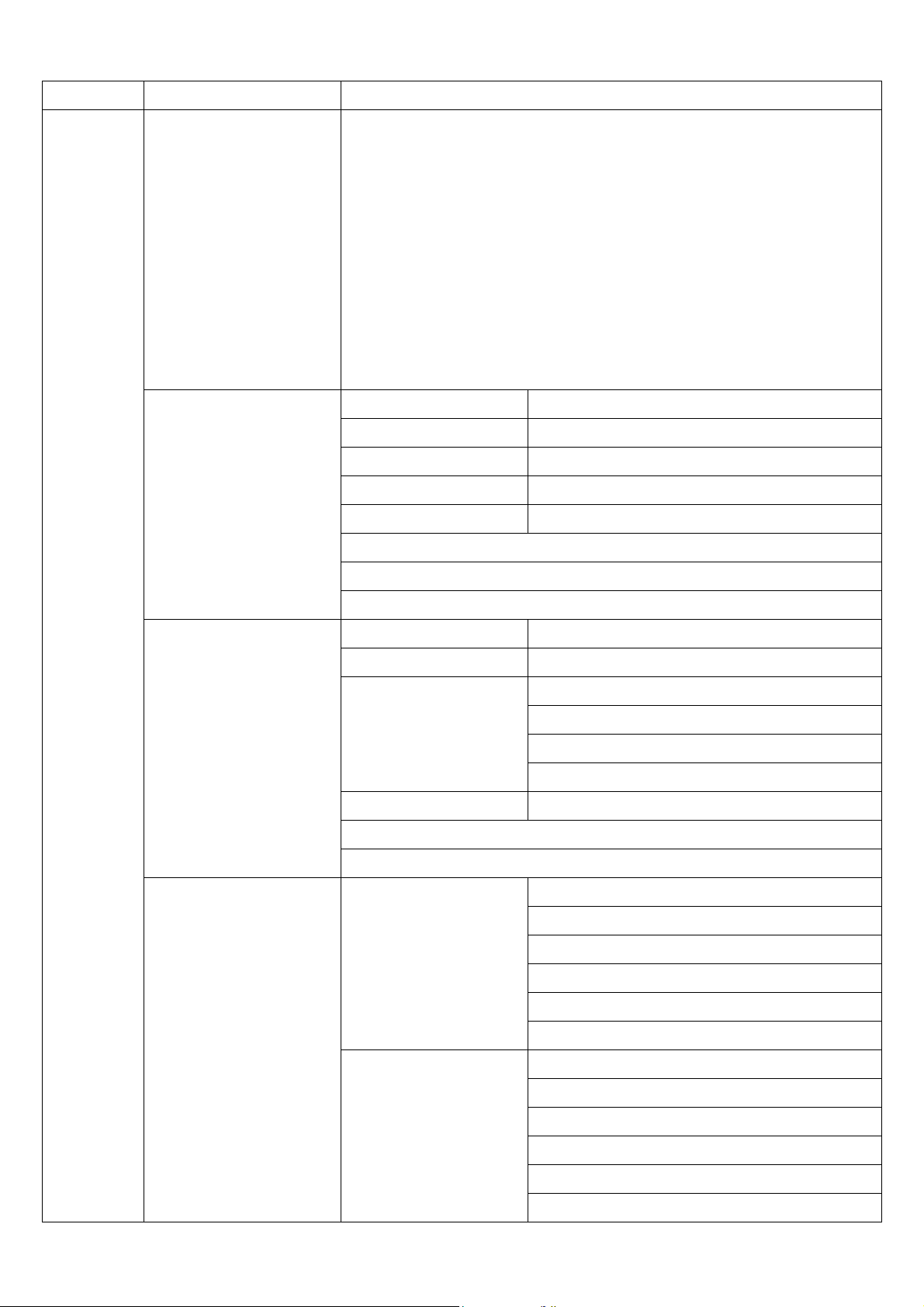
OSD MENU :
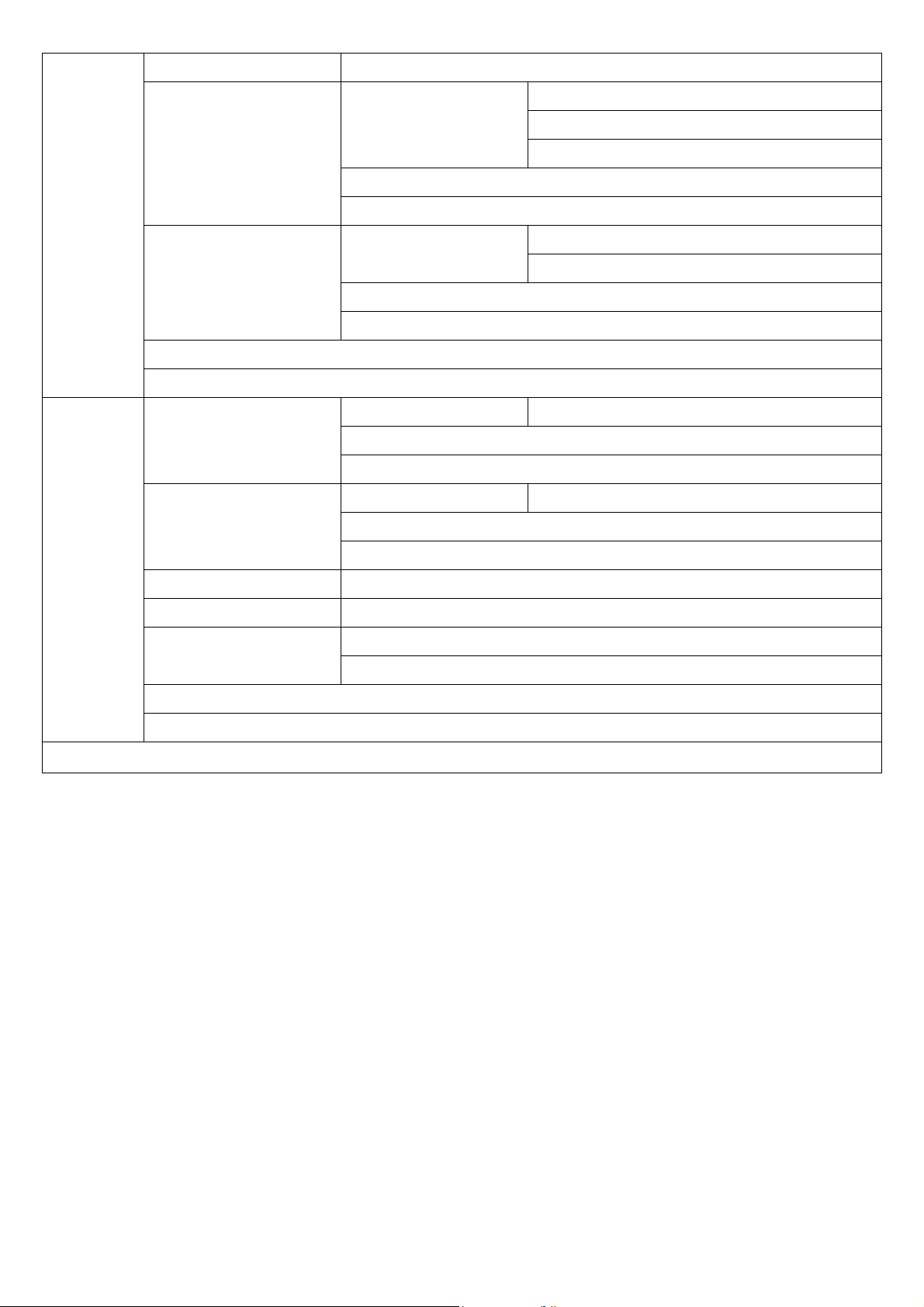
MAIN SUB MENU DESCRIPTION
OUTPUT RESULTION 480P 1366x768
576P 1440x900
720P50 1600x1200
720P60 1680x1050
1080P24 1920x1200
1080P50 BACK
1080P60, Default EXIT
1024x768
1280x800
1280x1024
SETUP
PICTURE SETTING OUT SELECT
CONTRAST 0~100, Default 50
BRIGHTNESS 0~100, Default 50
SATURATION 0~100, Default 50
HUE 0~100, Default 50
RESET
BACK
EXIT
OSD SETTING MENU TIMEOUT
INFO TIMEOUT
INFO POSITION RIGHT TOP
INFO DISPLAY
BACK
OUT1~OUT4, Default OUT1
0~100, Default 20
0~100, Default 5
LEFT TOP , Default
RIGHT BUTTON
LEFT BUTTON
ON, OFF, Default ON
EXIT
EDID INPUT1 EDID
INPUT2 EDID
1080P 2CH, Default
1080P MLT
OUTPUT 1
OUTPUT 2
OUTPUT 3
OUTPUT 4
1080P 2CH, Default
1080P MLT
OUTPUT 1
OUTPUT 2
OUTPUT 3
OUTPUT 4
7
Page 9
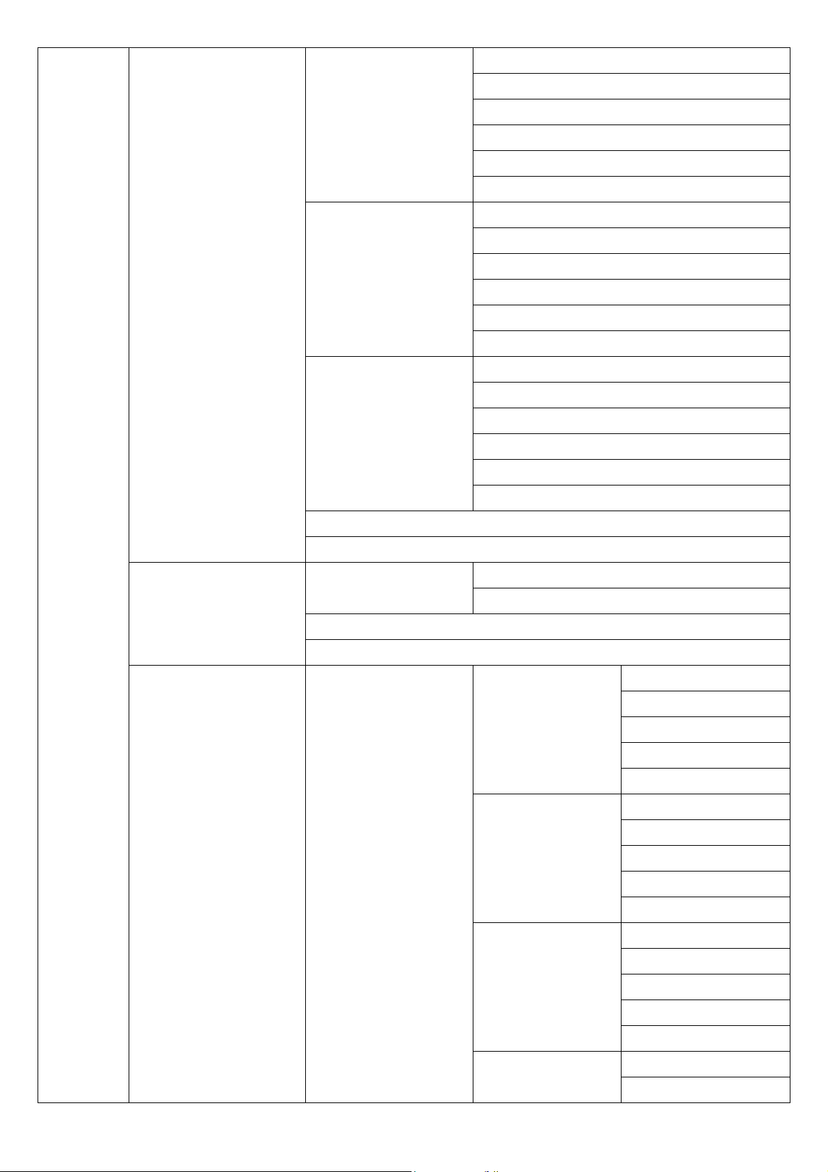
INPUT3 EDID
1080P 2CH, Default
1080P MLT
OUTPUT 1
OUTPUT 2
OUTPUT 3
OUTPUT 4
INPUT4 EDID
INPUT ALL
BACK
EXIT
HDCP HDCP
1080P 2CH, Default
1080P MLT
OUTPUT 1
OUTPUT 2
OUTPUT 3
OUTPUT 4
1080P 2CH, Default
1080P MLT
OUTPUT 1
OUTPUT 2
OUTPUT 3
OUTPUT 4
FOLLOW INPUT, Default
ALWAYS ON
BACK
EXIT
AUDIO MULTIVIEW MODE OUTPUT1 AUDIO
OUTPUT 2 AUDIO IN 1
OUTPUT 3 AUDIO IN 1
IN 1, Default
IN 2
IN 3
IN 4
OFF
IN 2, Default
IN 3
IN 4
OFF
IN 2
IN 3, Default
IN 4
OFF
OUTPUT 4 AUDIO IN 1
IN 2
8
Page 10
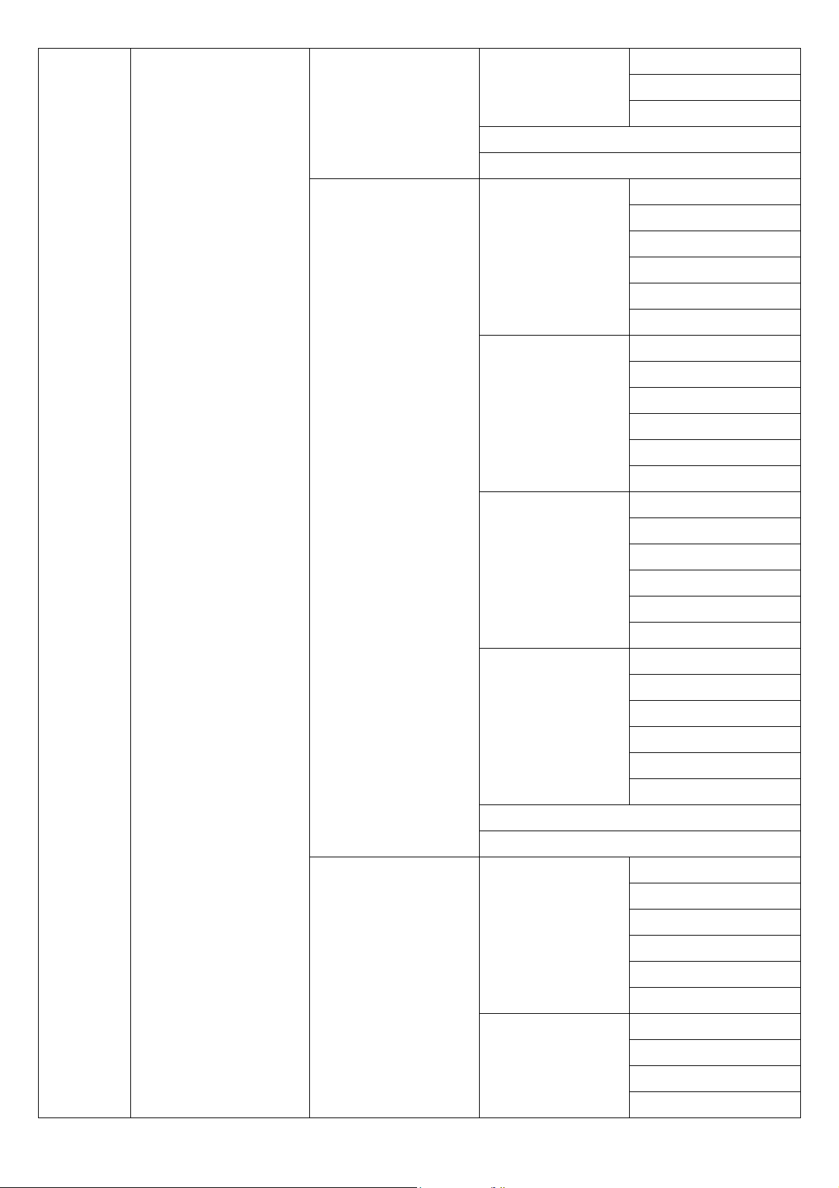
IN 3
IN 4, Default
OFF
BACK
EXIT
MATRIX MODE OUTPUT1 AUDIO IN 1
IN 2
IN 3
IN 4
FOLLOW, Default
OFF
OUTPUT 2 AUDIO IN 1
IN 2
IN 3
IN 4
FOLLOW, Default
OFF
OUTPUT 3 AUDIO IN 1
IN 2
IN 3
IN 4
FOLLOW, Default
OFF
OUTPUT 4 AUDIO IN 1
IN 2
IN 3
IN 4
FOLLOW, Default
OFF
BACK
EXIT
VIDEO WALL OUTPUT 1 AUDIO IN 1
IN 2
IN 3
IN 4
FOLLOW, Default
OFF
OUTPUT 2 AUDIO IN 1
IN 2
IN 3
IN 4
9
Page 11
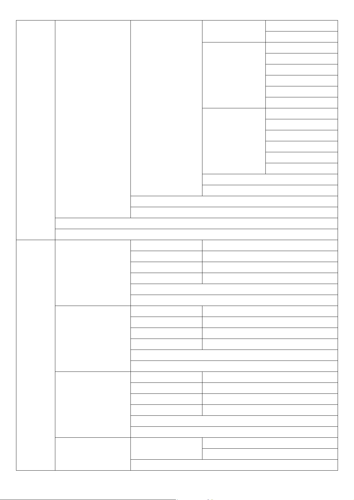
FOLLOW, Default
OFF
OUTPUT 3 AUDIO IN 1
IN 2
IN 3
IN 4
FOLLOW, Default
OFF
OUTPUT 4 AUDIO IN 1
IN 2
IN 3
IN 4
FOLLOW, Default
OFF
BACK
EXIT
NETWORK
BACK
EXIT
BACK
EXIT
IP ADDRESS BYTE 1 192
BYTE 2 168
BYTE 3 0
BYTE 4 200
BACK
EXIT
SUBNET MASK BYTE 1 255
BYTE 2 255
BYTE 3 255
BYTE 4 0
BACK
EXIT
GATEWAY IP BYTE 1 192
BYTE 2 168
BYTE 3 0
BYTE 4 1
BACK
EXIT
DHCP CLIENT DHCP CLIENT ON
OFF, Default
BACK
10
Page 12
EXIT
MEDIA TYPE MEDIA TYPE 10M
100M
AUTO, Default
BACK
EXIT
MAC FILTER MAC FILTER ON
OFF, Default
BACK
EXIT
BACK
EXIT
SYSTEM
EXIT
DEVICE ID DEVICE ID
BACK
EXIT
REMOTE ID REMOTE ID
BACK
EXIT
FACTORY DEFAULT FACTORY DEFAULT
REBOOT REBOOT
INFORMATION FIRMARE V1.00
WEB V1.0
BACK
EXIT
0~99, Default 0
0~9, Default 0
11
Page 13
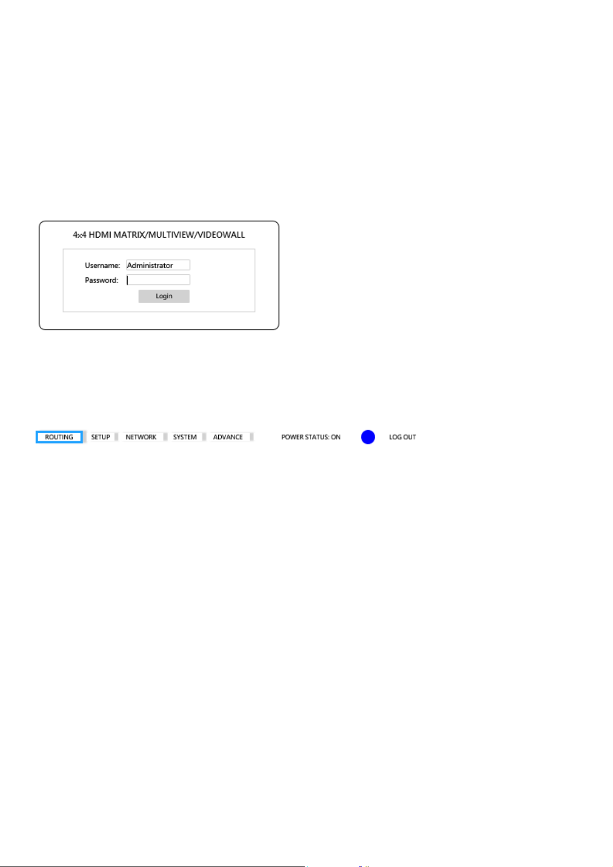
WebGUI Control:
Initial IP Configuration
1. Setup host IP Address same as your PC with same subnet.(Default 192.168.0.200)
To change IP Address please enter OSD menu by panel button or IR remote control.
2. Enter IP Address in your web browser and you could link to the web page of host.
3. Browser support: Internet Explorer 9, Chrome 42.0.2311.135 m, Firefox 31.0 and higher
WebGUI Operating:
LOGIN:
USERNAME : admin
PASSWORD : 123
MAIN PAGE:
ROUTING:Include MULTIVIEW, MATRIX, VIDEOWALL three mode
SETUP:OUTPUT RESOLUTION, HDCP SETTING, ID SETTING, PICTURE SETTING, OSD
SETTING
NETWORK:IP ADDRESS, SUBNET MASK GATEWAY, DHCP CLIENT, MEDIA TYPE, MAC
FILTER
SYSTEM:change password
ADVANCE:Adjust user define layout of MULTIVIEW mode
12
Page 14
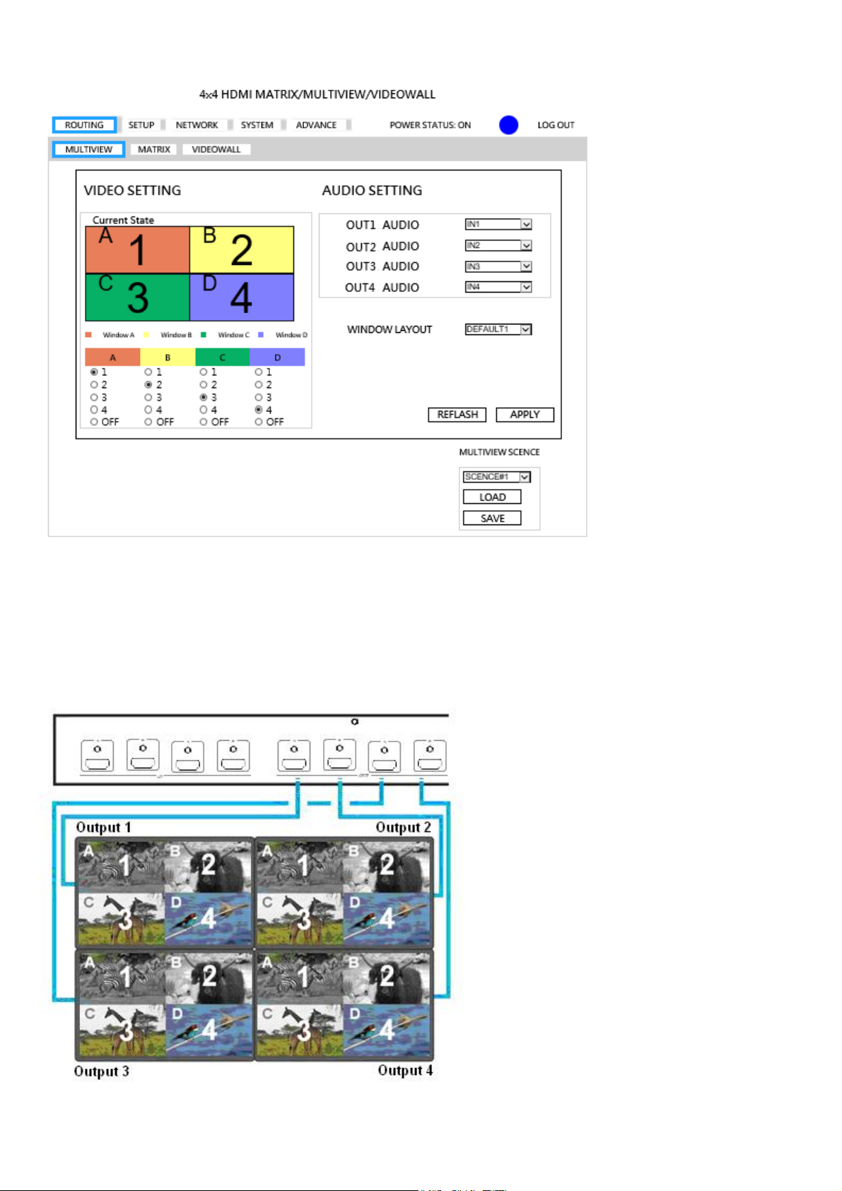
Multiview
VIDEO SETTING:Select video source of window A~D to input 1~4 or off
AUDIO SETTING:Select audio source of output 1~4 from input 1~4 or off
WINDOW LAYOUT:Select windows layout from default 1~4 or user define 1~4
MULTIVIEW SCENCE:Select SCENCE 1~8 to load or save
REFRESH:Refresh the information of host
APPLY:Apply changes
Note: When in Multiview mode,
adjustment to the picture settings
controlled through the OSD menu
or WebGUI (contrast, brightness,
saturation, hue) will effect the
specific quadrant of all displays
("OUT1" for A,"OUT2" for B,"OUT3"
for C or "OUT4" for D), regardless of
which video source A,B,C or D is
showing.
13
Page 15
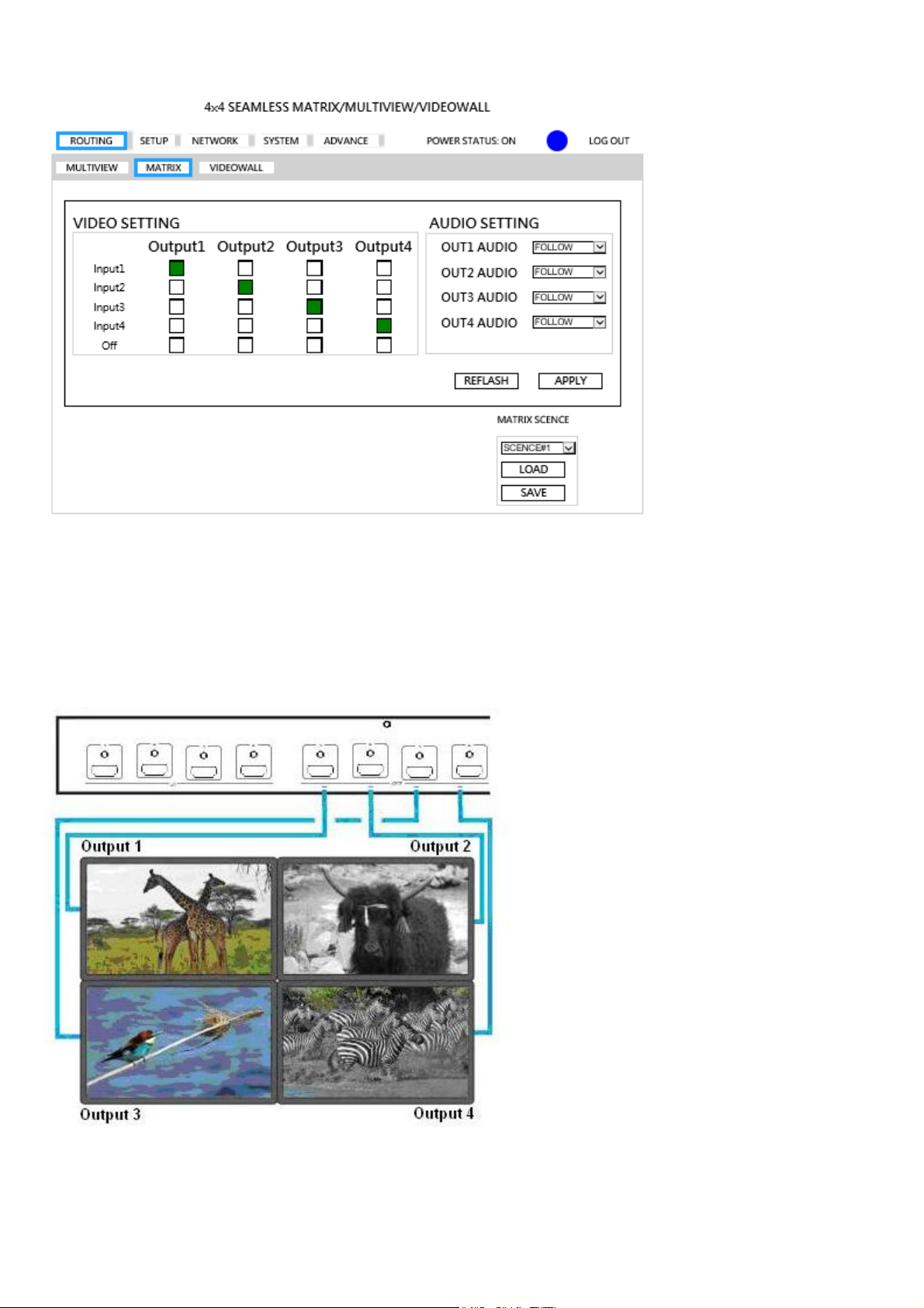
Matrix
VIDEO SETTING:Select video source of output 1~4 to input 1~4, off or follow.
AUDIO SETTING:Select audio source of output 1~4 from input 1~4,off or follow
MATRIX SCENCE:Select SCENCE 1~8 to load or save
REFRESH:Refresh the information of host
APPLY:Apply changes
Note: When in Matrix mode, adjustment to
the picture settings controlled through the
OSD menu or the WebGUI (contrast,
brightness, saturation, hue) will effect the
specific input sources and subsequent
screen images.
14
Page 16
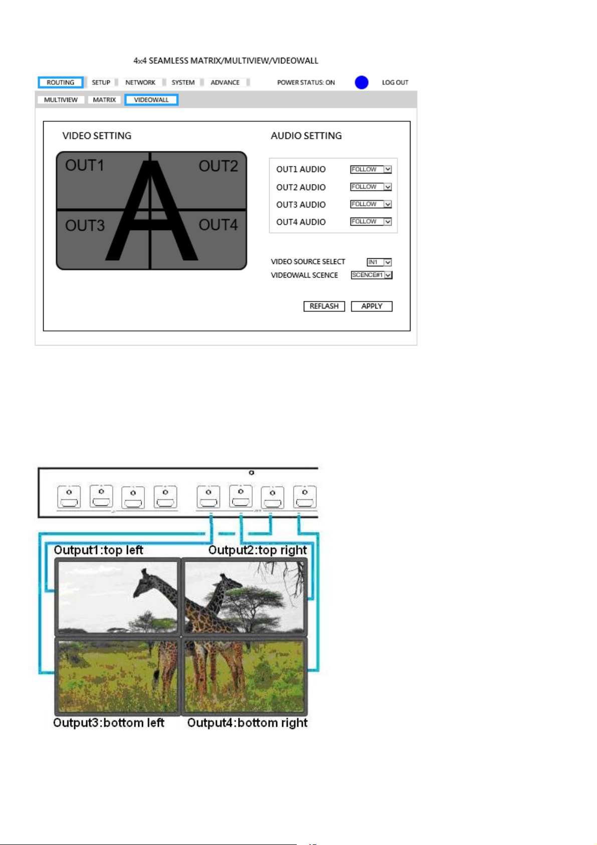
VIDEOWALL
VIDEO SETTING:Display videowall block of output 1~4
AUDIO SETTING:Select audio source of output 1~4 from input 1~4,off or follow
Video SCENCE:Select SCENCE 1~4 to load
REFRESH:Refresh the information of host
APPLY:Apply changes
*SCENCE 1 is factory default
15
Page 17
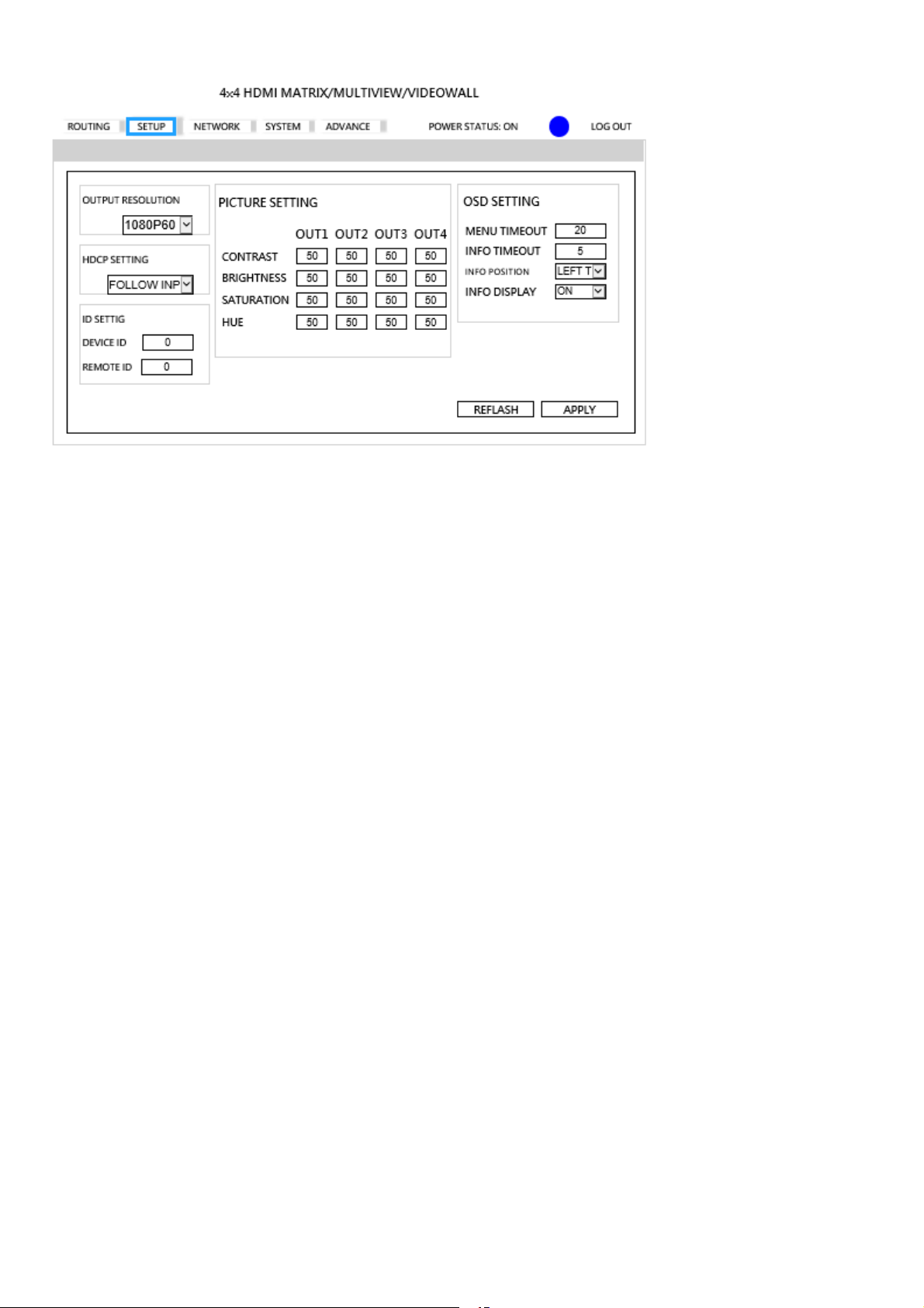
SETUP
OUTPUT RESOLUTION:Support 480P, 576P, 720P50, 720P60, 1080P24, 1080P50,
1080P60,Default 1080P60, 1024x768, 1280x800, 1280x1024, 1366x768, 1440x900, 1600x1200,
1680x1050, 1920x1200
HDCP SETTING:Set HDCP always on or follow input.
ID SETTING:Set DEVICE ID, Default 0, REMOTE ID, Default 0
PICTURE SETTING:Set CONTRAST, BRIGHTNESS, SATURATION, HUE of output 1~4,
Default 50
OSD SETTING:Set MENU TIMEOUT, Default 20s, INFO TIMEOUT, Default 5s, INFO
POSITION, Default LEFT TOP, INFO DISPLAY, Default ON
REFRESH:Refresh the information of host
APPLY:Apply changes
16
Page 18
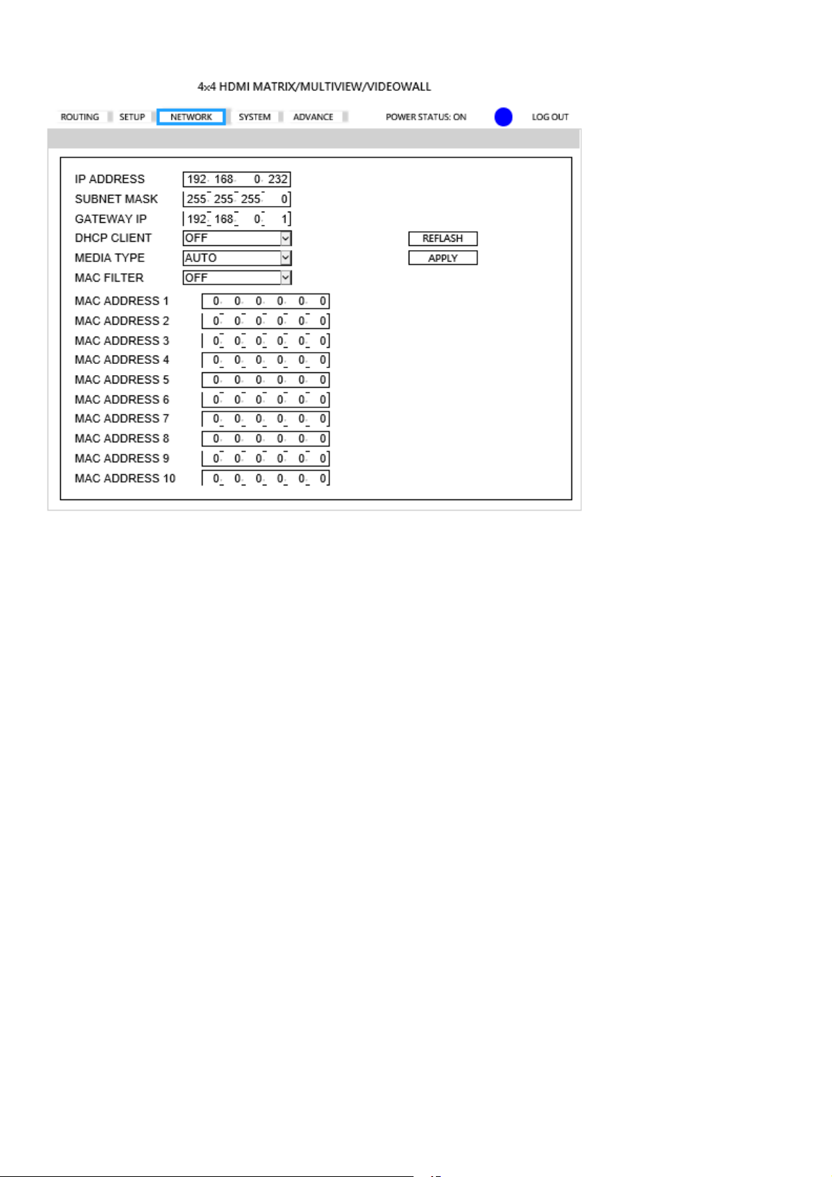
NETWORK
IP ADDRESS:Set IP address, Default 192.168.0.200
SUBNET MASK:Set Subnet mask, Default 255.255.255.0
GATEWAY:Set gateway address, Default 192.168.0.1
DHCP CLIENT:
ON:Get IP Address, Subnet Mask, Gateway from existing DHCP server
OFF:Set IP Address, Subnet Mask, Gateway by WebGUI or OSD menu manually, Default OFF
MEDIA TYPE:Set link speed of Ethernet port to 10 / 100 / Auto detect, Default AUTO
MAC FILTER: Add up to 10 registered MAC Address, only the MAC address which is in the list
can be able to connect host by Ethernet, Default OFF.
REFRESH:Refresh the information of host
APPLY:Apply changes
17
Page 19
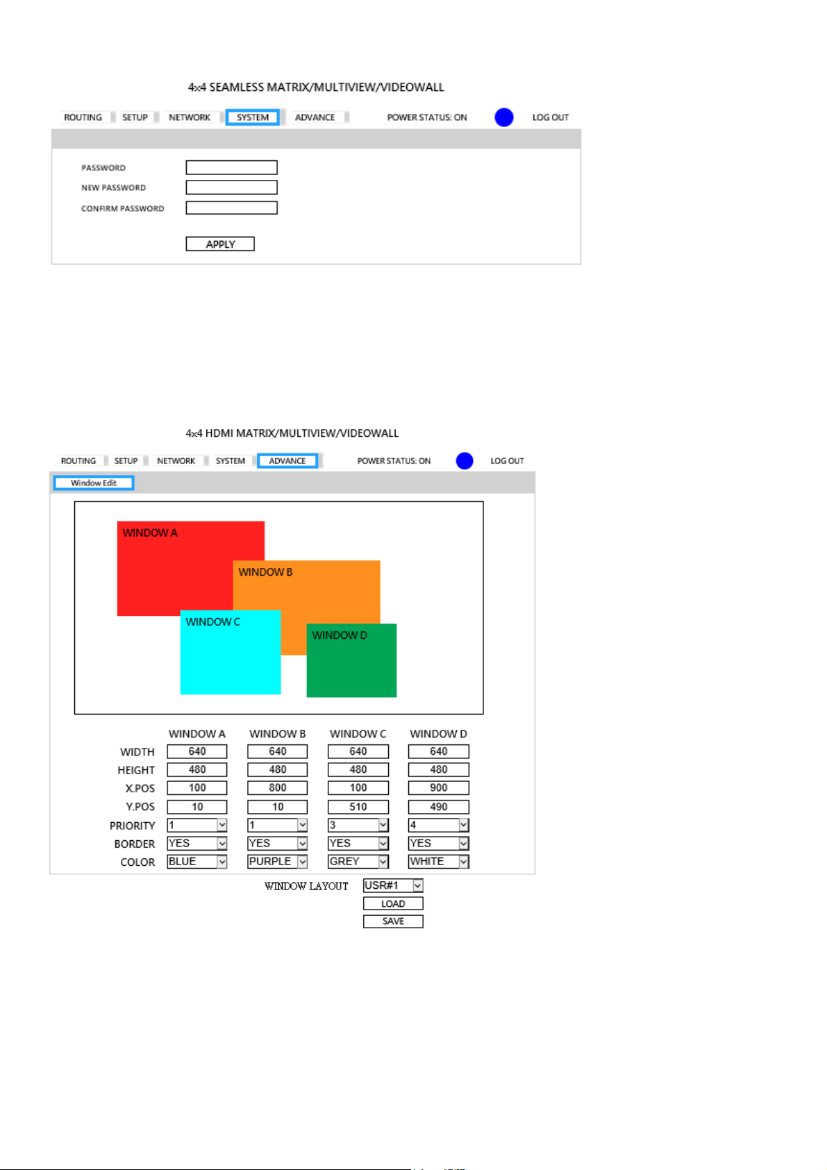
SYSTEM
PASSWORD:Enter old password, Default 123
NEW PASSWORD:Enter new password
CONFIRM PASSWORD:Enter new password again to confirm
APPLY:Apply changes
ADVANCE
(THIS FEATURE IS NOT AVAILABLE AS OF THIS PRINTING)
WIDTH, HEIGHT: Set size of the windows.
X.POS,Y.POS: Set top left position of window by x, y coordinate.
PRIORITY: Set the priority of windows, 1 is top and 4 is bottom.
BORDER: Select YES to show border of window, select NO to disable.
COLOR: Set color of border.
WINDOW LAYOUT:Select windows layout from user define 1~4 to load or save
LOAD: Select windows layout from user define 1~4 to modify
SAVE: Save windows layout to user define 1~4 after change the value
18
Page 20

RS232 remote control command:
Connect the RS232 CONSOLE port to the COM port of the host by an F/M RS232 straight cable (pin 2 to pin 2;
pin 3 to pin 3, pin 5 to pin 5)
Communication format is 9600, 8, N, 1 (9600 bps, 8 data bits, no parity check, 1 stop bit)
Operation Instruction format:
Command + △(Space) + Parameter + Enter
[Command] [Description]
----------------------------------- -------------------------------------------
POWER y Power on/standby
SMOUT1 n Output 1 from input n in seamless matrix
SMOUT2 n Output 2 from input n in seamless matrix
SMOUT3 n Output 3 from input n in seamless matrix
SMOUT4 n Output 4 from input n in seamless matrix
SMOUTALL n All output from input n in seamless matrix
SMADOOUT1 n Output 1 audio source from input n in seamless matrix
SMADOOUT2 n Output 2 audio source from input n in seamless matrix
SMADOOUT3 n Output 3 audio source from input n in seamless matrix
SMADOOUT4 n Output 4 audio source from input n in seamless matrix
SMADOOUTAll n All output audio source from input n in seamless matrix
MVWINA n Window A from input n in multiview
MVWINB n Window B from input n in multiview
MVWINC n Window C from input n in multiview
MVWIND n Window D from input n in multiview
MVWINALL n Set all windows from input n in multiview
MVADOOUT1 n Output 1 audio source from input n in multiview
MVADOOUT2 n Output 2 audio source from input n in multiview
MVADOOUT3 n Output 3 audio source from input n in multiview
MVADOOUT4 n Output 4 audio source from input n in multiview
MVADOOUTALL n All output audio source from input n in multiview
VDWALLRX n Input port n in video wall
VDWALLADOOUT1 n Output 1 audio source from input n in video wall
VDWALLADOOUT2 n Output 2 audio source from input n in video wall
VDWALLADOOUT3 n Output 3 audio source from input n in video wall
VDWALLADOOUT4 n Output 4 audio source from input n in video wall
VDWALLADOOUTALL n All output audio source from input n in video wall
DHCP y DHCP Client on/off
IP_ADDRESS [x.x.x.x] Set IP address
SUBNET_MASK [x.x.x.x] Set subnet mask
GATEWAY [x.x.x.x] Set gateway
MEDIA_TYPE z Set Ethernet link speed
MAC FILTER y MAC filter on/off
VERSION Display firmware version
HELP Show all commands
[SYMBOL] [PARAMETER]
--------------------------------------------------------------------------
N 0 | 1 | 2 | 3 | 4
n=0(OFF) n=1(INPUT1) n=2(INPUT2) n=3(INPUT3) n=4(INPUT4)
y 00=OFF, 01=ON
z 00=10M, 01=100M 02=AUTO
[x.x.x.x] Ethernet parameter
EX.192.168.0.1
Example:
SMADOOUT1△03 Set output 1 switch to input 3 in MATRIX mode
MVADOOUT3△04 Set output 3 switch to input 4 in MULTIVIEW mode
VDWALLADOOUT3△02 Set audio output from input 2 in VIDEOWALL mode
Commands are case insensitive.
The host will reply OK once string is correct, NG in case of incorrect string
19
Page 21
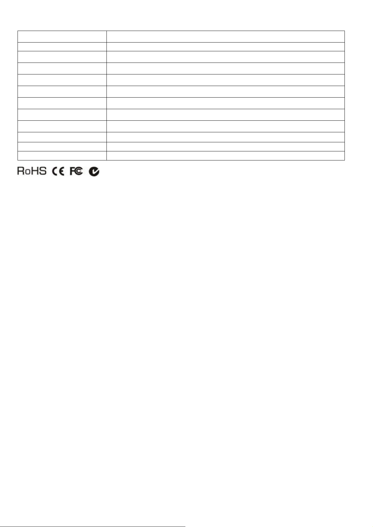
Specification:
ITEM NO.
SPLITMUX-4X4-HDVWC
Resolution 480i/p, 576i/p, 720p, 1080i/p@60Hz
HDMI Input
HDMI Type A x 4
HDMI Output
Ethernet Connector
RS232 Connector
IR Carrier
Power Supply
Power Consumption
Temperature
Operation: 0 to 55℃, Storage: -20 to 85℃, Humidity: up to 95%
HDMI Type A x 4
RJ45 x 1
DB9 Male x 1 (Console)
± 45 degree
DC 12V 4.16A
2A (Max)
Dimensions mm 483 x 177 x 44
Weight g 2300
20
 Loading...