

Page 1
V
NTI
NETWORK
R
TECHNOLOGIES
INCORPORATED
1275 Danner Dr
Aurora, OH 44202
www.networktechinc.com
Tel:330-562-7070
Fax:330-562-1999
EEMUX®Series
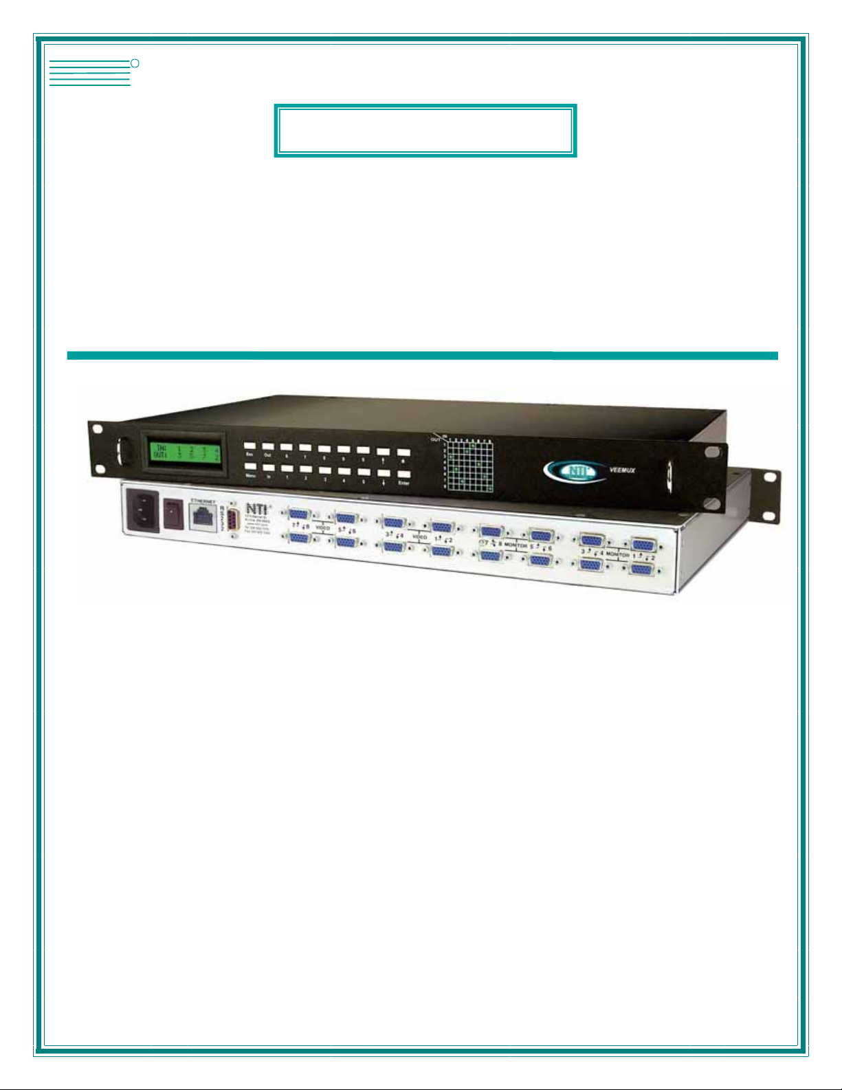
SM-nXm-15V-LCD
Video Matrix Switch
Installation and Operation Manual
MAN067 Rev Date 5/14/2007
Page 2

TRADEMARK
VEEMUX is a registered trademark of Network Technologies Inc in the U.S. and other countries.
COPYRIGHT
Copyright © 1999-2007 by Network Technologies Inc. All rights reserved. No part of this publication may be reproduced, stored
in a retrieval system, or transmitted, in any form or by any means, electronic, mechanical, photocopying, recording, or otherwise,
without the prior written consent of Network Technologies Inc, 1275 Danner Drive, Aurora, Ohio 44202.
CHANGES
The material in this guide is for information only and is subject to change without notice. Network Technologies Inc reserves the
right to make changes in the product design without reservation and without notification to its users.
FIRMWARE VERSIONS
Front Panel LCD Firmware Version 1.2
Ethernet Control Firmware Version 1.15
i
Page 3

TABLE OF CONTENTS
Introduction.................................................................................................................................................................... 1
Basic Operation ........................................................................................................................................................... 1
Supported Web Browsers............................................................................................................................................ 1
Compatibilty ................................................................................................................................................................. 1
Ordering Information.................................................................................................................................................... 1
SM-nXm-15V-LCD.................................................................................................................................................... 1
Options...................................................................................................................................................................... 1
Materials ...................................................................................................................................................................... 2
Cables.......................................................................................................................................................................... 2
Default User Name and Passwords ............................................................................................................................2
Features and Functions................................................................................................................................................3
Installation...................................................................................................................................................................... 4
Connect the Sources and Monitors ............................................................................................................................. 4
Connect RS232 ...........................................................................................................................................................5
Connect to the Ethernet............................................................................................................................................... 5
Power Up ..................................................................................................................................................................... 6
LED Matrix...................................................................................................................................................................... 6
Control Options .............................................................................................................................................................7
Front Panel LCD with Keypad Control......................................................................................................................... 7
Scan Mode................................................................................................................................................................ 8
RS232 Control ............................................................................................................................................................. 8
Remote Connection .................................................................................................................................................. 8
Baud Rate ................................................................................................................................................................. 9
Unit Address .............................................................................................................................................................9
Command Protocol ...................................................................................................................................................9
Autostatus............................................................................................................................................................10
Matrix Switcher's Control Program For Windows 9X, NT, 2000 AND XP ................................................................. 11
SerTest- RS232 Interface Test Program ...................................................................................................................11
Main Options...........................................................................................................................................................11
Matrix Operations....................................................................................................................................................11
Ethernet Operations................................................................................................................................................ 12
Setup Options ......................................................................................................................................................... 12
Ethernet Control ..........................................................................................................................................................13
Telnet Interface-Port 2000 ......................................................................................................................................... 13
Port 2005 Protocol ..................................................................................................................................................... 14
Command Summary............................................................................................................................................... 14
Command Detail ..................................................................................................................................................... 14
RU-Read Unit Size .............................................................................................................................................. 14
RO-Read Connection for Output Port .................................................................................................................15
CS- Connect Output Port to Input Port................................................................................................................ 15
CA- Connect All Output Ports to Input Port ......................................................................................................... 15
SS_01- Enable Auto Status Mode....................................................................................................................... 15
SS_00- Disable Auto Status Mode...................................................................................................................... 16
SX- Examine connections ...................................................................................................................................16
Terminate telnet session .....................................................................................................................................16
Web Interface ............................................................................................................................................................17
Enter the Password ................................................................................................................................................17
Video Switch Page ..............................................................................................................................................18
Setup Pages ........................................................................................................................................................ 19
Video Input Names ..............................................................................................................................................20
Output Names......................................................................................................................................................21
Outputs Scanning Sequences............................................................................................................................. 21
Update Firmware ................................................................................................................................................. 23
Change Password Page......................................................................................................................................24
Help Page............................................................................................................................................................ 24
Update Web Server ............................................................................................................................................. 24
Logout Page ........................................................................................................................................................ 25
ii
Page 4

Device Discovery Tool................................................................................................................................................ 26
Infrared Control ........................................................................................................................................................... 27
Features And Functions............................................................................................................................................. 27
Keypad.................................................................................................................................................................... 27
LCD Display ............................................................................................................................................................ 27
How To Use The IRT ................................................................................................................................................. 28
Change the Switch.................................................................................................................................................. 28
Change Output Port................................................................................................................................................ 29
Change Input Port................................................................................................................................................... 29
Set Configuration .................................................................................................................................................... 30
Battery Replacement ................................................................................................................................................. 31
Specifications............................................................................................................................................................. 31
IRT Troubleshooting .................................................................................................................................................. 31
DDC Support................................................................................................................................................................ 32
RS232 Upgrade OF the Front Panel LCD Firmware.................................................................................................33
RS232 Connection Cables.......................................................................................................................................... 35
Pinout of RS232 port on VEEMUX ............................................................................................................................ 35
Specifications for Straight-Through Serial Cable for CPU Connection ..................................................................... 35
Pinout for Matrix Y-1 Cable........................................................................................................................................36
Rack Mounting Instructions ....................................................................................................................................... 36
Specifications .............................................................................................................................................................. 37
Troubleshooting ..........................................................................................................................................................38
Safety Statements ....................................................................................................................................................... 38
Index ............................................................................................................................................................................. 38
Warranty Information .................................................................................................................................................. 38
TABLE OF FIGURES
Figure 1- Install Video Source Cables................................................................................................................................................4
Figure 2- Connect a monitor to the VEEMUX .................................................................................................................................... 4
Figure 3- Connect user terminal for RS232 control............................................................................................................................ 5
Figure 4- Connect the LAN to the VEEMUX ......................................................................................................................................5
Figure 5- LED Matrix showing input 5 connected to output 5............................................................................................................. 6
Figure 6- RS232 connection with Matrix-Y-1 cable............................................................................................................................9
Figure 7- Web interface Welcome page.........................................................................................................................................17
Figure 8- Web interface Login Prompt .............................................................................................................................................17
Figure 9- Web interface Switch page............................................................................................................................................... 18
Figure 10- Web interface Setup page .............................................................................................................................................. 19
Figure 11- Web interface Serial Setup page .................................................................................................................................... 20
Figure 12- Web interface Video Input Names page .........................................................................................................................20
Figure 13- Output Port Names.........................................................................................................................................................21
Figure 14- Outputs Scanning Sequences page ............................................................................................................................... 21
Figure 16- Web interface Update Firmware page ............................................................................................................................ 23
Figure 17- Web interface Password page........................................................................................................................................ 24
Figure 18- Updating the Web Server ...............................................................................................................................................24
Figure 19- Web interface Logout page.............................................................................................................................................25
Figure 20- Device Discovery Tool page ........................................................................................................................................... 26
iii
Page 5
NTI VEEMUX VIDEO MATRIX SWITCH
INTRODUCTION
The SM-nXm-15V-LCD (n = number of inputs (video sources), m = number of outputs (monitors)) video matrix switch (VEEMUX)
allows any of up to 32 video sources to output to any or all of up to sixteen (16) monitors. The configuration of the VEEMUX is
determined at time of order (i.e. 16x4, 8x16, etc.). The bandwidth of the SM-nXm-15V-LCD is 200MHz and video resolutions
through 1900 x1200 are supported with no degradation. The switch can be controlled with the Front Panel Keypad, RS232
interface, Ethernet, or an optional Infrared Remote.
The VEEMUX can be ordered in many sizes and with several control options. The base unit includes a user keypad, an RS232
port, and an Ethernet port to make up a complete system. The infrared option, purchased separately, allows for maximum user
satisfaction in each unique configuration.
Basic Operation
The VEEMUX allows any source to be connected to any destination at any time with no restrictions or limitations.
• Video inputs accept any RGBHV, RGBS, or RGsB signal.
• Video outputs are compatible with any RGBHV or RGBS monitor, regardless of input. (RGsB monitor requires
RGsB input)
Supported Web Browsers
Most modern web browsers should be supported. The following browsers have been tested:
• Microsoft Internet Explorer 6.0 or higher
• Netscape 7.0 or higher
• Mozilla FireFox 0.9.2 or higher
Set your browser to always check if there is a newer version of the page than the version stored in cache. This action will ensure
that it will display the most up-to-date information.
Compatibilty
The SM-nXm-15V-LCD is made to support video inputs from VGA (15HD – H & V Sync) only.
Ordering Information
The SM-nXm-15V-LCD is built to a specific size ranging from 2, 4, 8, 12, or 16 monitors and 4 to 32 video sources. The “n” in the
part number represents the number of video sources. Select a switch built for 4, 8, 16, or 32 video sources. The “m” in the part
number represents the number of outputs (monitors). A switch built for 2, 4, 8, 12, or 16 monitors may be ordered. It is not
necessary to fully populate all of the connectors on the unit (ex. an SM-16x8 switch has the capability of supporting 16 video
sources and 8 monitors, but it will operate with only 14 video sources with 7 monitors connected.
SM-nXm-15V-LCD
Replace the “n” with 4,8,16, or 32
Replace the “m” with either 2, 4 ,8,12,or 16
The following list represents the available sizes that can be ordered:
SM-4x2-15V-LCD SM-8x2-15V-LCD SM-16x2-15V-LCD SM-32x2-15V-LCD
SM-4x2-15V-LCD-DT* SM-8x2-15V-LCD-DT* SM-16x4-15V-LCD SM-32x4-15V-LCD
SM-4x4-15V-LCD-DT* SM-8x4-15V-LCD SM-16x8-15V-LCD SM-32x8-15V-LCD
SM-4x4-15V-LCD SM-8x4-15V-LCD-DT* SM-16x12-15V-LCD SM-32x16-15V-LCD
SM-8x8-15V-LCD SM-16x16-15V-LCD
*-DT = Desktop chassis instead of rack mount chassis
Options
DDC Support (see page 32)
This feature makes the DDC information of the monitor connected to port 1 available to each CPU.
This feature is ordered by adding a "D" following the size designation in the model number (i.e. SM-8X2D-15V-LCD)
Infrared Control (see page 27)
This feature adds the ability to control the VEEMUX via an infrared remote.
This feature is ordered by adding the suffix "-IR" to the model number when ordering (i.e. SM-4X2-15V-LCD-IR)
1
Page 6
NTI VEEMUX VIDEO MATRIX SWITCH
Materials
Materials Supplied with this kit:
• NTI SM-nXm-15V-LCD Video Matrix switch
• IEC Line cord, country specific
• 4-#10-32 x 3/4" pan head screws and 10-32 cagenuts (server cabinet mounting hardware)
• CD with: a pdf file of this owner's manual
the NTI Discovery Tool
the Matrix Switcher's Control Program
Cables
All cables are sold separately. The following tables list the available stocked cables with their length in feet. All VGA input and
output connectors on Matrix Switches are FEMALE. When using multi-coax high resolution VGA to BNC cables, the BNC
connectors are also FEMALE for input and output. Custom cables are available – contact NTI for pricing and distance / resolution
limitations.
NTI NAME DESCRIPTION
VGA
VEXT-3/6/10/15/25/35/50/75/100-MM
VEXT-3/6/10/15/25/35/50/75/100
VINT-5B-6
Matrix-Y-1 or see page 31 for
alternative cables
Contact NTI for various lengths and
colors
Multi-coax high resolution VGA or SVGA video cable. Connectors are 15HD male-male
(used for INPUTS)- 3 thru 100 feet
Multi-coax high resolution VGA or SVGA video cable. Connectors are 15HD malefemale (used for OUTPUTS)-3 thru 100 feet
Multi-coax high resolution VGA to BNC cable. Connectors are 15HD male to 5 BNC’s-6
feet long
RS232
RS232 Interface Cable- Connectors are 9D male- female-female 12" long
(also see alternative cable specifications on page 35)
ETHERNET
Cat5 UTP Cable- Connectors are RJ45 male-Stocked cables are 2 thru 100 feet
Custom cables must have RJ45 connectors wired straight thru- pin 1 to pin 1, etc.
Default User Name and Passwords
The default Telnet password is admin (lower case letters only) . For instruction on using Telnet, see page
13.
(No username is required in order to use Telnet. You will only be prompted for a password.)
The default Web Interface user name
The default Web Interface password
Interface, see page 17.
is Administrator (upper case letter for "A" only).
is admin (lower case letters only). For instruction on using the Web
2
Page 7
NTI VEEMUX VIDEO MATRIX SWITCH
4
56
ETHERN ET
7
R
S
2
3
2
NTI
Network Technologies Inc
NTI
1275 Danner Dr
Aurora, OH 44202
www.nti1.co m
Tel:330-562-7070
Fax:330-562-1999
R
R
1
6
Out
Esc
1 2 3In4
Menu
2
7890
3
IN
5
1234 678
OUT
1
2
3
DDC
4
*
5
Enter
5
6
7
8
10
VEEMUX
Rear View of SM-8X8-15V-LCD
VIDEO VIDEO MONITOR MONITOR
Front View of SM-8X8-15V-LCD
7 8 5 6 3 4 1 2 8 5 6 3 4 1 2
8
7
9
R
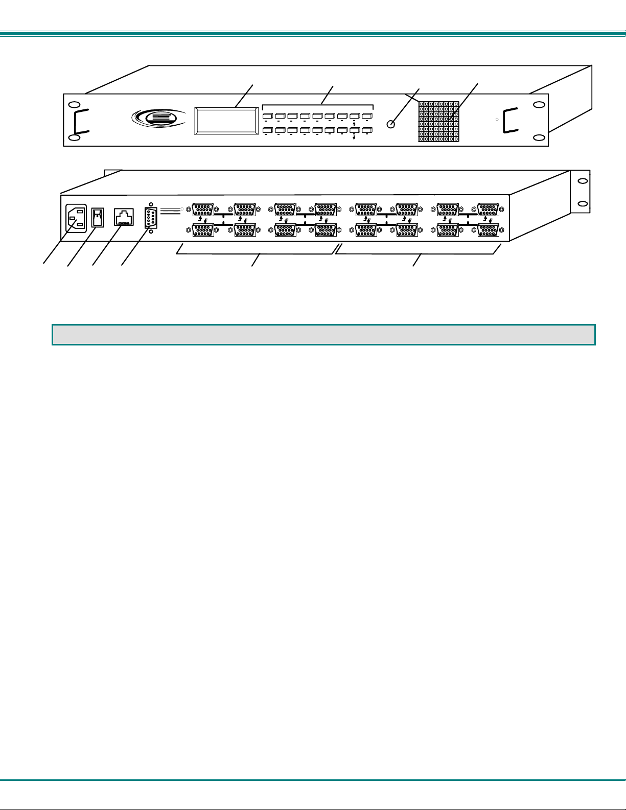
FEATURES AND FUNCTIONS
1. LCD Display- for visual indication of connection between the monitor and a specific video source.
2. Keypad buttons- for user control over switch functions
3. DDC button- for manual update of DDC information between the monitor and the CPU(s) attached
(optional- see page 28)
4. IEC Power Connector- for attachment of power cord
5. Power ON/OFF switch
6. Ethernet- RJ45 female connector- for connection of CAT5 cable to LAN for WEB interface (not available on models in
desktop chassis (-DT))
7. RS232- female 9D connector- for attaching RS232 interface cable from a CPU to control the functions of
one or more switches
8. VIDEO x - female 15HD connectors- for connection of video source cables
9. MONITOR x- female 15HD connectors- for connection of monitors
10. LED Matrix- for visual indication of all input-to-output connections (page 6) (not available on all models)
Note: Some models have user-accessible overcurrent protection fuses. These fuses are replaceable with 2A 240VAC
Fast-blo fuses.
3
Page 8
NTI VEEMUX VIDEO MATRIX SWITCH
INSTALLATION
Connect the Sources and Monitors
1. Turn OFF power to all video sources (inputs) that will be connected to the VEEMUX before connecting or
disconnecting any cables.
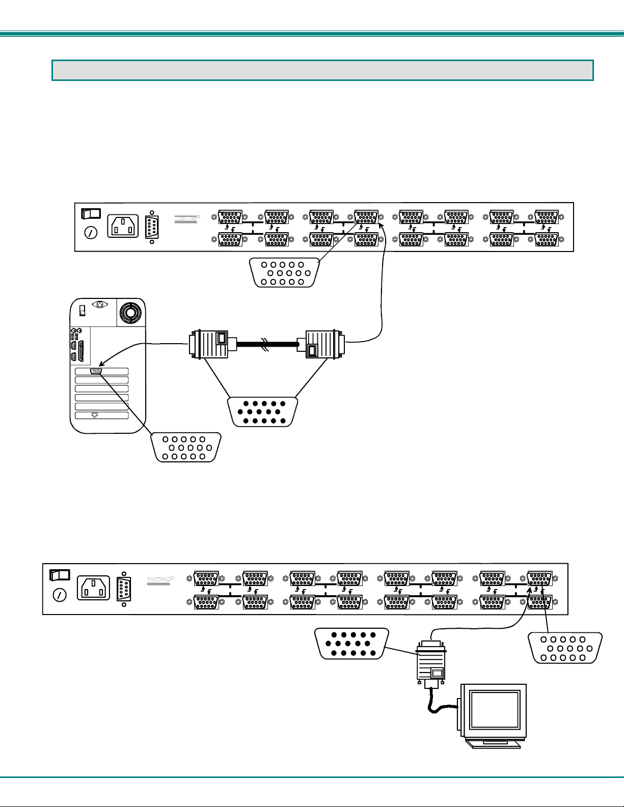
2. Connect a VEXT-xx-MM cable from the video port of a video source to a 15HD female video connector
labeled VIDEO 1 on the VEEMUX. (See Fig. 1)
3. Connect additional video sources to remaining 15HD female VIDEO x connectors as desired.
R
S
2
3
2
NTI
1275 Danner Dr
Aurora, OH 44202
www. nti1.c om
Tel:330-562-7070
Fax:330-562-1999
R
7 8 5 6 3 4
HD15-Male
Rear View of
Video Source
CPU)
15HD female
Video Connector
Figure 1- Install Video Source Cables
4. Connect a monitor to the 15HD female connector labeled MONITOR 1 on the rear of the VEEMUX (See Fig. 2).
5. Connect additional monitors to remaining 15HD female MONITOR x connectors as desired.
R
S
2
3
2
NTI
1275 Danner Dr
Aurora, OH 44202
www.nti1.com
Tel:330-562-7070
Fax:330-562-1999
R
VIDEO VIDEO MONITOR MONITOR
7 8 5 6 3 4
Rear View of SM-8X8-15V-LCD
VIDEO VIDEO MONIT OR MONIT OR
15HD female
Video Connector
VEXT-xx-MM
15HD male
Video Connector
HD15-Male
1 2
8 5 6 3 4 1 2
7
Rear View of SM-8X8-15V-LCD
1 2
15HD male
Video Connector
8 5 6 3 4 1 2
7
VGA
Multi-Scan
Monitor
15HD female
Video Connector
Figure 2- Connect a monitor to the VEEMUX
4
Page 9
NTI VEEMUX VIDEO MATRIX SWITCH
Connect RS232
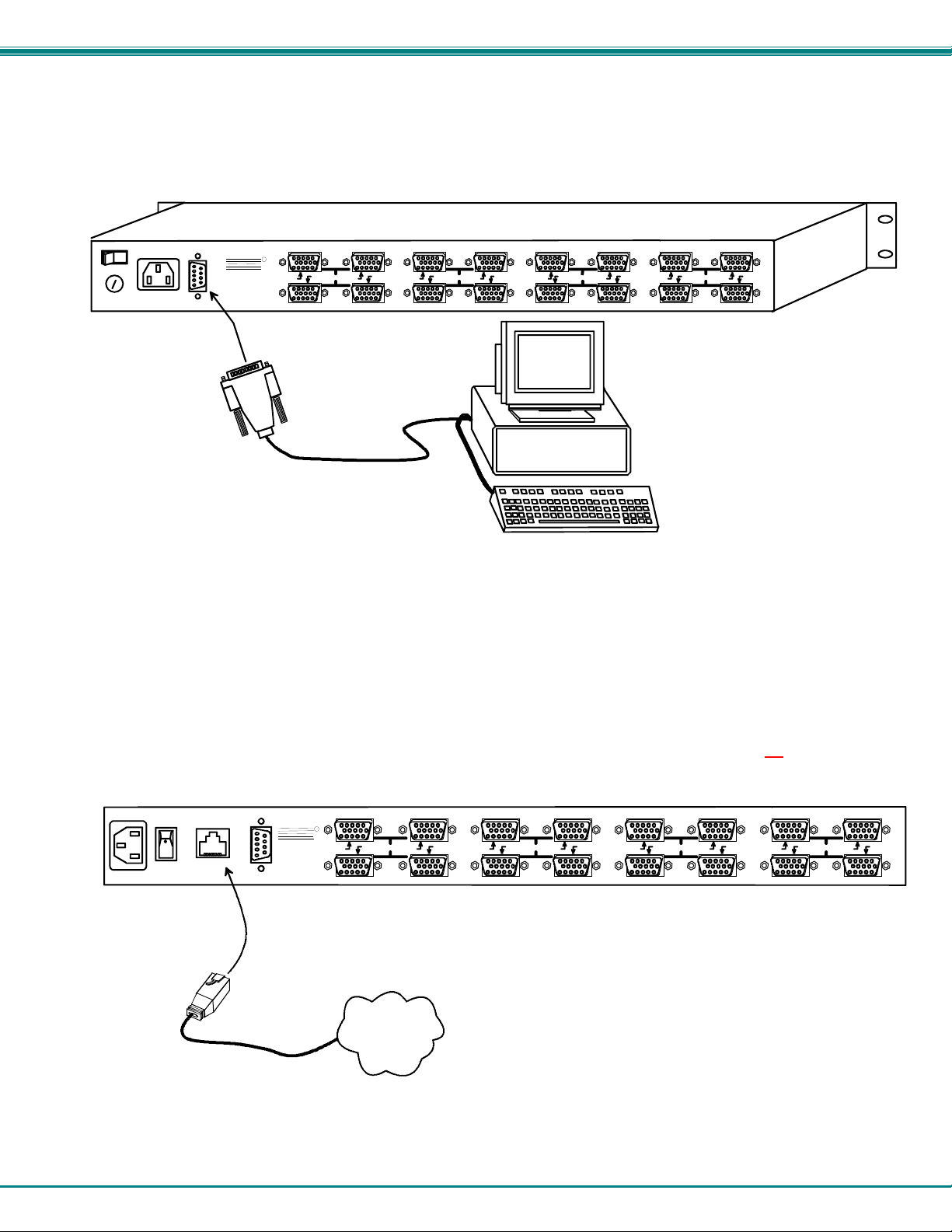
RS232 control can be achieved using a separate user terminal or CPU with a terminal program. To make a terminal connection,
connect a serial cable (specifications on page 31) between the user terminal and the 9 pin DIN female connector on the VEEMUX
labeled "RS232". (See Fig. 3)
R
S
2
3
2
NTI
1275 Danner Dr
Aurora, OH 44202
www. nti1.com
Tel:330-562-7070
Fax:330-562-1999
R
7 8 5 6 3 4 1 2 8 5 6 3 4 1 2
9D-male
RS232 connector
Rear View of SM-8X8-15V-LCD
VIDEO VIDEO MONITOR MONITOR
7
VGA
Multi-Scan
Monitor
User Terminal
Figure 3- Connect user terminal for RS232 control
Connect to the Ethernet
If the Telnet Interface (page 13) or Web Interface (page 14) will be used, an Ethernet connection to the Local Area Network (LAN)
must be made using CAT 5 cable with RJ45 connectors. Wiring between the connectors should be straight through (pin 1 to pin
1, pin 2 to pin 2, etc.) Connect a CAT 5 cable between the connector label "ETHERNET" and the LAN (see Fig. 4).
Note: The Ethernet connection is not available in models in a desktop chassis (i.e. SM-8X2-15V-LCD-DT
ETHERNET
NTI
1275 Danner Dr
Aurora, OH 44202
www. nti1.com
Tel:330-562-7070
Fax:330-562-1999
R
7 8 5 6 3 4
R
S
2
3
2
Rear View of SM-8X8-15V-LCD
VIDEO VIDEO MONITOR MONITOR
1 2
8 5 6 3 4 1 2
7
RJ45 male
connector
LAN
)
Figure 4- Connect the LAN to the VEEMUX
5
Page 10
NTI VEEMUX VIDEO MATRIX SWITCH
Power Up
1. Plug the VEEMUX into an AC power outlet.
2. Turn ON power to the VEEMUX.
3. Turn ON power to the video sources and monitors connected to the VEEMUX.
LED MATRIX
(not available on all models)
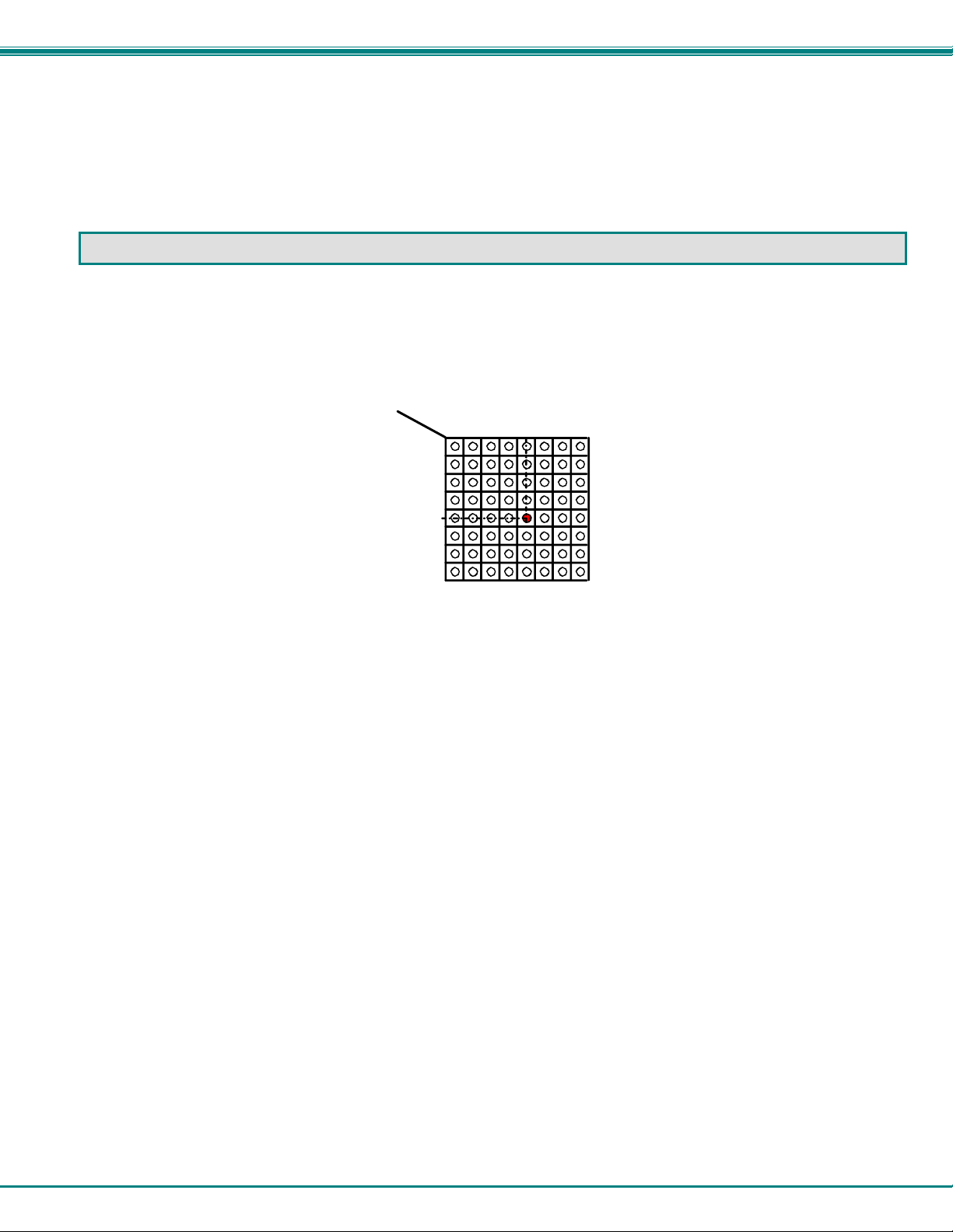
The LED Matrix is a grid of LEDs on the front panel of the VEEMUX. This grid is used to provide a visual indication of all
connections between video sources and destinations. To determine if an input (video source) is connected to an output (video
destination), follow the LEDs down and to the right (respectively) until they intersect. The illuminated LED at the point of
intersection indicates the input is connected to the output by the VEEMUX.
OUT
IN
1234 678
1
2
3
4
5
6
7
8
5
Figure 5- LED Matrix showing input 5 connected to output 5
6
Page 11
NTI VEEMUX VIDEO MATRIX SWITCH
CONTROL OPTIONS
The VEEMUX video matrix switch has four methods of control:
• Front Panel LCD with Keypad
• Directly via an RS232 Interface
• Remotely via Ethernet (rack mount models only)
• Infrared Remote (optional).
Every unit comes standard with the Front Panel LCD with Keypad, and RS232 built in. Rack mount models also include Ethernet
connection. If desired, the Infrared option must be requested at the time of the order. The Infrared option requires the purchase
of a separate remote control device (Infrared transmitter) as well as an Infrared receiver to be installed in the VEEMUX. No
software is involved (see Infrared Control on page 23). With the RS232 option, there are no external devices to be purchased.
NTI provides software commands as well as a test program to ensure the RS232 functions properly (see page 8 – RS232
Control).
Front Panel LCD with Keypad Control
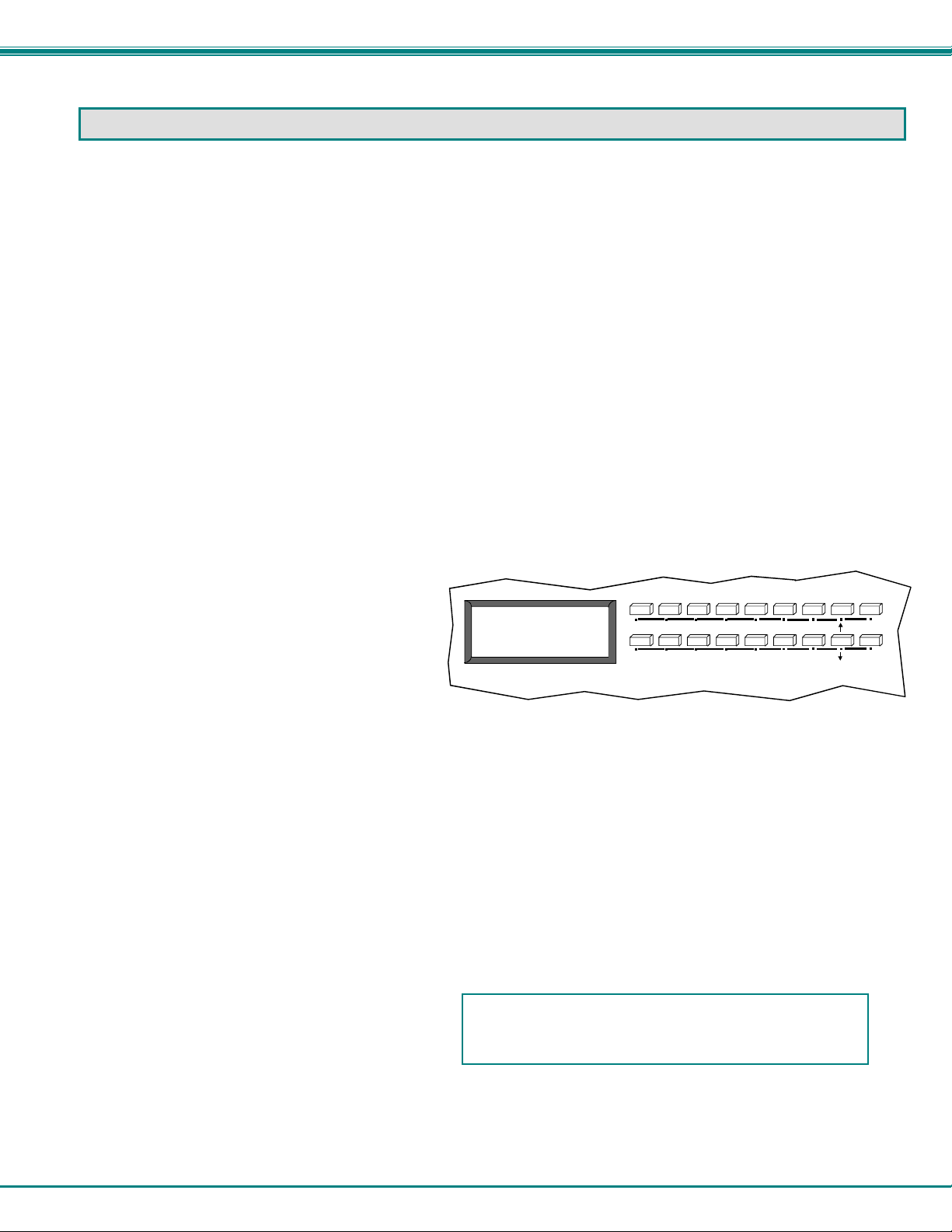
The front panel LCD and keypad allow the user to monitor switch status and route any user to any video source on the switch.
When the unit is powered up, each monitor is automatically connected to the video source of its equal number (i.e. monitor 1 to
source 1, monitor 2 to source 2, monitor 3 to source 3, etc.). Along with the routing of the inputs (video sources) to the outputs
(monitors) the keypad and LCD allow the users to configure the RS-232 control interface. The keypad buttons perform the
following functions.
ESC Escape back to the main display.
0 – 9 Used to enter numbers. ( # )
OUT The output user number can be entered
(2 digits or 1 digit and ENTER or IN)
OUT: 1 2 3 4
IN: 1 2 3 4
ESC
MENU
followed by the input
IN Used following single digit output entries
ENTER Used following single digit entries
Display next 4 outputs and their inputs
Display previous 4 outputs and their inputs
MENU The RS-232 menu is displayed. This allows the baud rate to be set at 9600, 2400, 1200 or 300 baud and the unit
address to be set to 1 - 15. See RS-232 control later in this chapter.
* Activate Memory Function - 100 memory locations 0 – 99, 0 is the power on default.
to Save current connections ( * ) ( OUT ) ( # ) ( ENTER )
to Recall connections from ( * ) ( IN ) ( # ) ( ENTER )
To set all outputs to one input ( * ) + ( # ) + (ENTER)
The following examples show various method of routing output 3 to input 5. Inputs and Outputs can be entered as a two digit
number or a one digit number followed by IN or ENTER.
(OUT) 3 (IN) 5 (ENTER)
(OUT) 3 (ENTER) 5 (ENTER)
(OUT) 03 05
Configurations that are saved into memory locations via
the keypad can be recalled via the web interface (page 18)
and vice versa.
3 (ENTER) 5 (ENTER)
03 05
Note: If the current switch configuration includes assigned Scan Mode dwell time values (pg. 8), to save the current
configuration be sure to assign a memory location to it. Otherwise, when the VEEMUX is powered OFF, all dwell time
values will be erased. Also, saving the configuration as memory location 0 will cause it to be the power-ON default
configuration.
Out
In
6
7890
1 2 3
*
5
4
ENTER
7
Page 12
NTI VEEMUX VIDEO MATRIX SWITCH
Scan Mode
Scan Mode causes an output port to automatically switch from one input port to the next consecutive input port after a specified
period of time (referred to as the dwell time). Port switching will continue indefinitely and no ports will be skipped, whether there
are video sources connected to them or not. If desired, the VEEMUX can be configured to skip the scanning of specific ports
using the RS232 Command Protocol (page 9) or Telnet (page 13).
Dwell time settings can be any value from 0 seconds (000) to 255 seconds. A setting of 000 seconds (the default setting)
disables Scan Mode for that output port. If Scan Mode is disabled for a specific port, then the video to that output will only
change as decided by the administrator.
To configure Scan Mode from the front panel LCD:
Press MENU, the following lines will be displayed:
1) Set Baud Rate
2) Set Unit Addr
Press MENU again, the following line will be displayed:
3) Set Scan Mode
Press 3 to select that menu item. The following request will be displayed:
Select Port
Select the output to be programmed using the numeric keys, then press ENTER. The display will show the current Dwell Time
value for that output and ask for a new value.
Current Time: 16
New Time:
Using the numeric keys, enter a value between 0 and 255 and press ENTER. Leading zeros are allowed (000) but the number
should not exceed 3 digits. The Scan Mode dwell setting value 0 will disable Scan Mode for that output port.
Scan Mode settings can also be configured through the RS232 Command Protocol (page 9), Telnet commands (page 13), or
through the Web Interface (page 17).
NOTE: Scan Mode configuration settings can only be saved if they are assigned a memory location via the Keypad
Control (page 7). Otherwise when the power is cycled to the VEEMUX, all Scan Mode settings will be erased.
TIP: If the Scan mode settings are stored as memory location 0, they will be loaded each time the VEEMUX is powered
ON.
NOTE: If Outputs Scanning Sequences (page 21)
Is enabled, Scan Mode as configured at the LCD
front panel will be disabled.
RS232 Control
RS232 enables the VEEMUX to be remotely controlled via RS232. To control the VEEMUX via RS232 the user has three
options:
• write a program that runs on a PC using the Command Protocol (page 9)
• use the Matrix Switcher's Control Program (page 11) provided on the CD
• use the SerTest program (page 11) provided on the CD
Remote Connection
The RS232 Interface is designed to control the switch via serial (RS232) daisy chain connection from any host computer or other
controller with an RS232 communications port. There is, however, a restriction that must be followed:
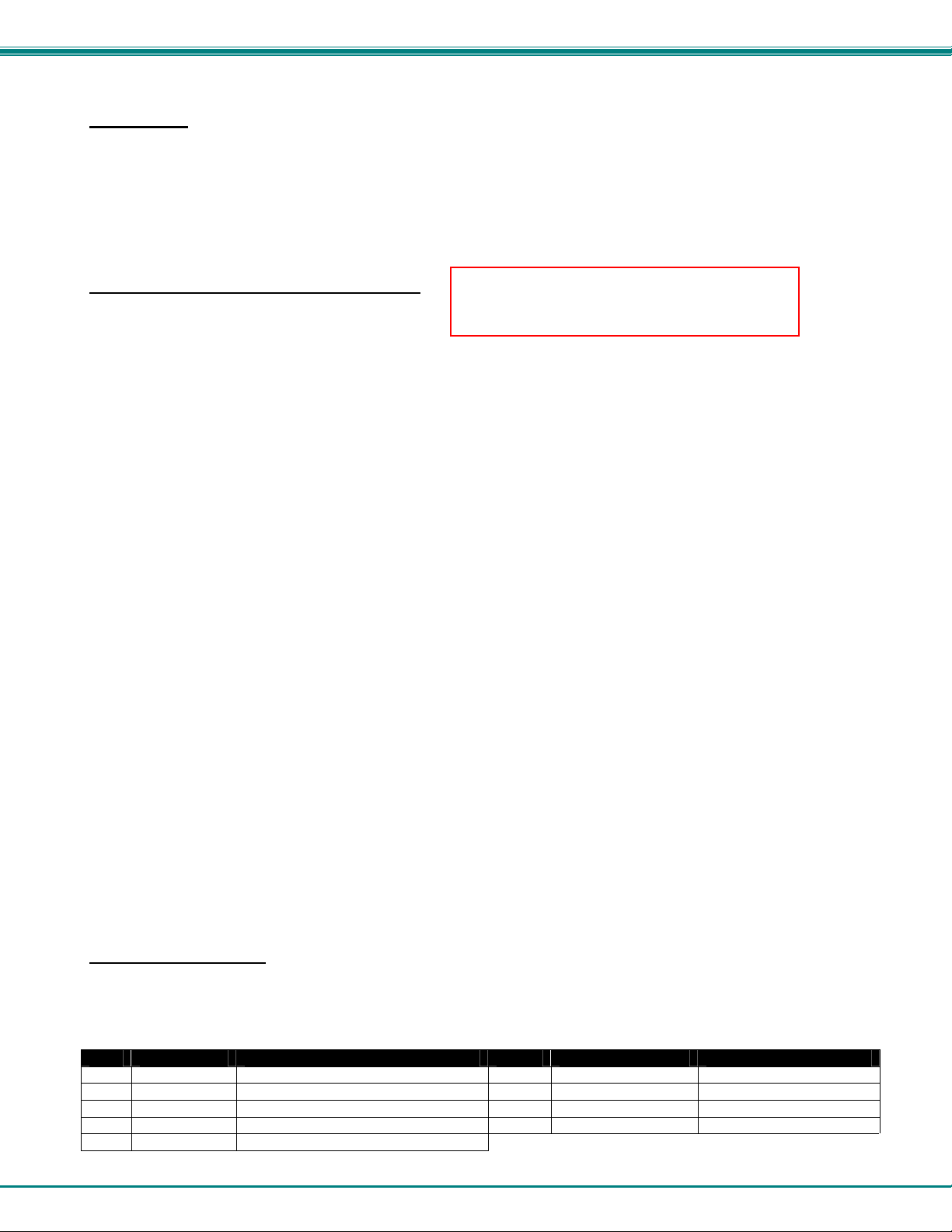
The pin outs for the DB-9 connector on the unit are as follows:
RS232 Connector (DB-9 FEMALE)
PIN SIGNAL FUNCTION PIN SIGNAL FUNCTION
1
None no connection
2 TXD Transmit Data (RXD at host) 7 CTS Clear to Send
3 RXD Receive Data (TXD at host) 8 RTS Request to Send
4 DSR Data Set Ready 9
5 GND Signal Ground
6 DTR Data Terminal Ready
none no connection
8
Page 13
NTI VEEMUX VIDEO MATRIX SWITCH
On the DB-9 female connector, pins 4 (DSR) and 6 (DTR) are shorted and pins 7 (CTS) and 8 (RTS) are shorted. Therefore, host
handshaking is bypassed and TXD and RXD are the only active signals. A straight through DB-9 cable (not null modem) will work
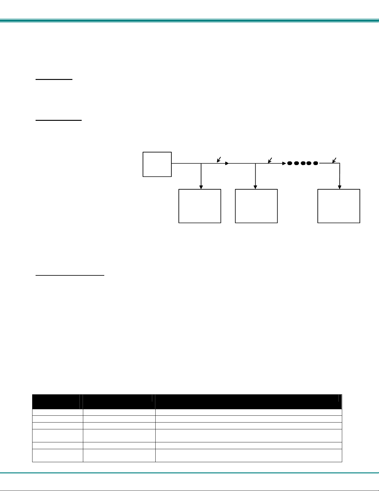
for most CPUs. To daisy chain multiple units, use NTI Matrix-Y-1 "Y" cables, except for the last unit connected. (see Fig 6). For a
pinout of the Matrix-Y-1 cable, see page 32. For straight through cable pinouts applicable to various terminal types, see page
31.
Baud Rate
The unit powers up with a default baud rate of 9600 and a fixed data protocol of 8 data bits, no parity and 1 stop bit. The baud
rate can be changed by pressing the MENU button on the front panel keypad. Then select 1 for SET BAUD RATE and select the
desired baud rate of 9600, 2400, 1200 or 300. A data protocol of 8 data bits, no parity, and 1 stop bit is used for communications.
Unit Address
To allow multiple units to be controlled from a single CPU port, the RS232 control interface is designed to allow "daisy chaining"
up to 15 units using the NTI Matrix-Y-1 "Y" cables. By setting the appropriate unit address with the keypad (the default address is
01), each unit can be given a unique address (1-15). Then the unit will only respond to commands on the bus if its address is
embedded in the command.
To set the unit address:
-select MENU on the front panel keypad
-select 2 for SET UNIT ADDRESS
-press the address number (1-15)
- press ENTER.
CPU
RS232
Serial Port
RS232
NTI
SWITCH
First Unit
Matrix-Y-1
Matrix-Y-1 Matrix-Y-1
RS232
NTI
SWITCH
Second Unit
RS232
NTI
SWITCH
Last Unit
Figure 6- RS232 connection with Matrix-Y-1 cable
Command Protocol
CPU controller commands supported by the unit are defined below. All commands should be terminated with a <CR> (carriage
return). When a command is sent, the entire string is echoed back along with a response from the addressed unit as shown in the
command definitions table below. All characters in the command string should be upper case, and all numbers below 10 should
have a leading 0 (ex: 1 = 01). As command strings are sent, the inner character delay cannot exceed 500 milliseconds.
Note: To use this command protocol, the user is required to write a program that will send an entire command string all
at once, not character by character. Programs that send one character at a time (such as HyperTerminal) cannot be used
to control the VEEMUX. Alternatively, the user may use the Matrix Switcher's Control Program or SerTest to control the
VEEMUX via RS232 (see page 11).
Legend: (All numbers must be two digits)
SW : Switch (01-15) (Unit Address) MM : Save Into Memory Bank (00-99)
BR : Baud Rate Code (12,24,48,96) LL : Load From Memory Bank (00-99)
OP : Output Port (01-MAXOUTPUTS) <CR> : Carriage Return (Hex 0xD)
IP : Input Port (01-MAXINPUTS) ip
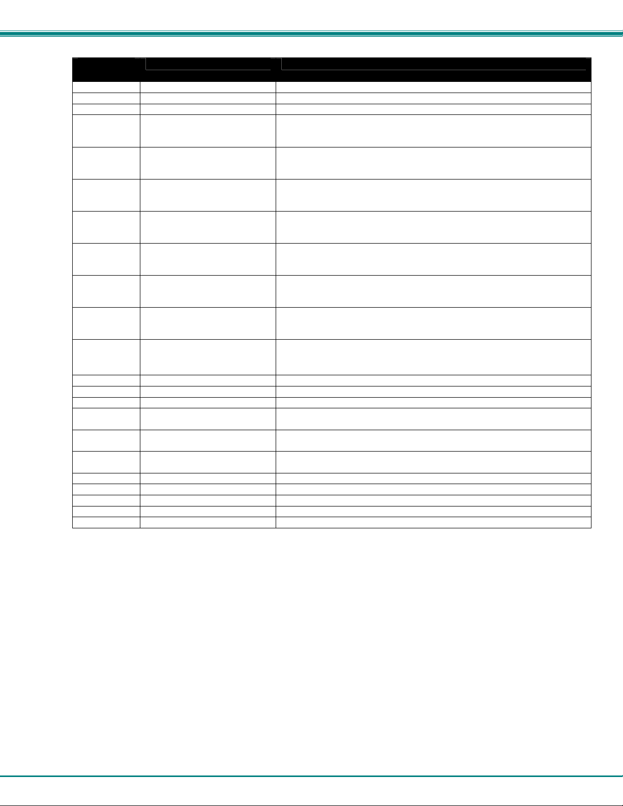
Command Definitions
Command
Good Response Description
String
CS SW,IP,OP *<CR> Connect One Output Port To Input Port
CA SW,IP *<CR> Connect All Output Ports To Input Port
RO SW,OP *<CR>IP<CR> Read Connection For Output/User Port
CC SW,MM *<CR>MM<CR> Save Matrix Connections Into Memory Bank xx
Xx=00-99
RC SW,LL *<CR>LL<CR> Restore Matrix Connections From Memory Bank
CB 00,BR None Change baud rate of serial line, BR=12(00),24(00),48(00),96(00)
Factory default is 9,600
: IP address
9
Page 14
NTI VEEMUX VIDEO MATRIX SWITCH
Command Definitions (Cont'd)
Command
Good Response Description
String
RS SW *<CR> Internal Reset
RV SW,00 *<CR>string\0<CR> Read NTI Version String
RU SW *<CR>IP,OP<CR> Read Unit Size
EA SW,ip *<CR> Set the IP address, ip is in xxx.xxx.xxx.xxx format,
number of digits is minimum 1 and maximum 3 for each field
Leading zeroes are accepted
EM SW,ip *<CR> Set the Subnet mask, ip is in xxx.xxx.xxx.xxx format,
number of digits is minimum 1 and maximum 3 for each field.
Leading zeroes are accepted
EG SW,ip *<CR> Set the default gateway, ip is in xxx.xxx.xxx.xxx format,
number of digits is minimum 1 and maximum 3 for each field
Leading zeroes are accepted
ET
SW,timeout
RA SW * <CR>ip<CR> Read the IP address, ip is in xxx.xxx.xxx.xxx format,
RM SW * <CR>ip<CR> Read the Subnet mask, ip is in xxx.xxx.xxx.xxx format,
RG SW * <CR>ip<CR> Read the default gateway, ip is in xxx.xxx.xxx.xxx format,
RT SW * <CR>timeout<CR> Read the website timeout; timeout = numeric value in seconds.
SS SW,00 *<CR> Disable Autostatus feature (see below)
SS SW,01 *<CR> Enable Autostatus feature (see below)
GO SW,OP *<CR>go SW,OP:IP<CR> Read connection of a Output Port to Input Port
GM SW,00 *<CR>go SW,OP:IP (all
Ss
SW,OP,DWT
Gs SW,OP *<CR>DWT<CR> Read scan mode dwell time setting for an Output port
Sa SW,OP *<CR> Set scan list of individual output to all inputs
Sc SW,OP *<CR> Clear scan list of individual output
S+ SW,OP,IP *<CR> Add individual input to Scan List of output
S- SW,OP,IP *<CR> Remove individual input from Scan List of output
Sx SW,OP *<CR>oooxoxxxooooxxx<CR> Inspect the Scan List of individual output (o=skip x=don't skip)
*<CR> Set the website timeout; timeout = numeric string of timeout in seconds.
Values: 60, 300, 600, 900, 1800, 3600, 7200, 18000, 28800
0 = no timeout
number of digits is minimum 1 and maximum 3 for each field
Leading zeroes are accepted
number of digits is minimum 1 and maximum 3 for each field
Leading zeroes are accepted
number of digits is minimum 1 and maximum 3 for each field
Leading zeroes are accepted
Values: 60, 300, 600, 900, 1800, 3600, 7200, 18000, 28800
0 = no timeout
Read connection matrix of all Output ports
ports)<CR>
*<CR>
Set Scan Mode dwell time for specific Output port
DWT values: 000-255 000= scan disabled See page 8 for more info.
DWT values: 000-255 000= scan is disabled for the port
If the first field is not a known command (as listed above) or SW field is different from the serial address programmed in the switch
memory, the command will be ignored. If the SW field corresponds to the unit address, but the syntax is wrong after this field, the
switch will answer with a bad response ?<CR>.
Autostatus
When Autostatus is enabled, any output-to-input connection change in the VEEMUX will cause an Autostatus message to be sent
via RS232 to the administrator. The format of the message would be "pc SW,OP:IP<CR>"
Example of an Autostatus message:
pc 01,01:04<CR>
which means "At the switch with unit address 01, the output (01) has changed connection to input 04."
Notes: Message to the administrator will be delayed by any RS232 traffic being received by the switch from the
administrator.
Autostatus must be disabled before using SerTest or the Matrix Switcher's Control Program (below).
By default, Autostatus is disabled and must be manually enabled. Autostatus is also disabled any time the power to the
VEEMUX is interrupted.
10
Page 15
NTI VEEMUX VIDEO MATRIX SWITCH
Matrix Switcher's Control Program For Windows 9X, NT, 2000 AND XP
The Matrix Switcher's Control Program is an easy and powerful graphical program that controls NTI matrix switches through an
RS232 interface. The Matrix Switcher's Control Program is included on the CD packaged with the VEEMUX. The Matrix
Switcher's Control Program is downloaded by clicking on the link "Download Matrix Switcher's Control Program" found on the
web page that appears when you insert the instruction manual CD into your CD ROM drive.
To install the Matrix Switcher's Control Program after downloading
1. Locate the Setup.exe in the directory the program was downloaded to and double-click on it
2. Follow the instructions on the screen
The Matrix Switcher's Control Program performs best on monitors set to a screen resolution of at least 800 X 600. Instruction for
using the Matrix Switcher’s Control Program is available by opening "MSCP Help" in the "NTI" program group once the program
has been installed and is open on the screen.
To open "MSCP Help" from the Windows desktop
1. Click on START
2. Click on PROGRAMS
3. Click on NTI
4. Click on MSCP Help
SerTest- RS232 Interface Test Program
This software allows a user to test the functions of an NTI server switch, matrix switch or Multi-user/Multi-platform switch RS232
interface. The program SERTEST along with the Matrix Switcher's Control Program (above) is installed from the CD packaged
with this switch. SERTEST generates a main menu with the 3 selections described below:
Main Options
• Matrix Operations
• Ethernet Operations
• Setup Options
• About SerTest
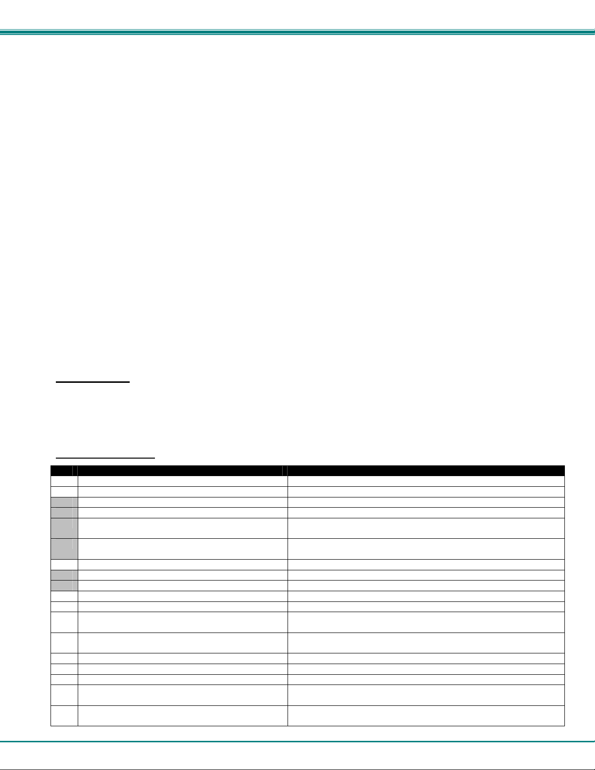
Matrix Operations
Key Selection Description
1) Connect Video Output/User to an Input/CPU - connect an output to an input
2) Connect All Video Outputs/Users to an Input/CPU - connect all outputs to an input
3) Connect Audio Output/User to an Input/CPU - connect an output to an input (audio ports only)
4) Connect All Audio Outputs/Users to an Input - connect all outputs to an input (audio ports only)
5) Change Mute Status for Audio Output/User (not
applicable to this unit)
6) Change Volume for Audio Output/User (not
applicable to this unit)
7) Read Connection for Video Output/User -read the connection of a specific video output
8) Read Connection for Audio Output/User -read the connection of a specific audio output
9) Read Mute and Volume for Audio Output/User - read the volume and the mute status of the specified audio output
a) Save I/O Connections into Unit Memory -save the connections into switch memory bank
b) Restore I/O Connections from Unit Memory -restore the connections from switch memory bank
c) Change All Units Baud Rate (9600/COM1:) -change RS-232 Baud rate of all switches
d) Reset Unit - send a reset command to the switch
e) Reset All Units - send an internal reset command to all switches
f) Read Unit Size - read the switch size (number of inputs and outputs)
g) Read Unit Version/Revision String -read a string containing the switch version, type, and size
h) Save All Units I/O Connections into Units Memory -save the connections into switch memory bank, command for all
i) Restore All Units I/O Connections from Units
Memory
Selections in the "Key" column that are gray are not applicable to this product.
- send commands to the matrix unit.
- set Ethernet connection variables
- set COM port, baud rate, and unit address
- display the program version
- mute or un-mute the Audio port output
- change Audio port output volume
-the current baud rate and serial port are displayed in parentheses
- the current unit address is displayed in parentheses
switches
-restore the connections from switch memory bank, command for all
switches
11
Page 16
NTI VEEMUX VIDEO MATRIX SWITCH
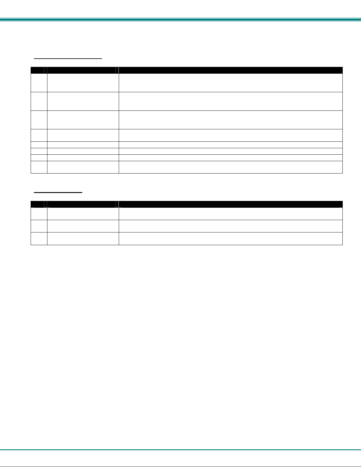
Ethernet Operations
Key Selection Description
1) Set Unit IP Address - enter the desired IP address in xxx.xxx.xxx.xxx format
- number of digits is minimum 1 and maximum 3 for each field. Leading zeroes are
accepted
2) Set Unit Subnet Mask
3) Set Unit Default Gateway - enter the desired default gateway
4) Set Unit Website Timeout - set the website timeout; timeout = numeric string of timeout in seconds
5) Read Unit IP Address - read the unit IP address in xxx.xxx.xxx.xxx format
6) Read Unit Subnet Mask - read the unit subnet mask in xxx.xxx.xxx.xxx format
7) Read Unit Default Gateway - read the unit default gateway in xxx.xxx.xxx.xxx format
8) Read Unit Website Timeout - read the current website timeout period in seconds
- enter the desired IP address in xxx.xxx.xxx.xxx format
- number of digits is minimum 1 and maximum 3 for each field. Leading zeroes are
accepted
- number of digits is minimum 1 and maximum 3 for each field. Leading zeroes are
accepted
- Values: 60, 300, 600, 900, 1800, 3600, 7200, 18000, 28800 0 = no timeout
- Values: 60, 300, 600, 900, 1800, 3600, 7200, 18000, 28800 0 = no timeout
Setup Options
Key Selection Description
1) select Com port current:
(COM1:)
2) select Baud rate current:
(9600)
3) set unit Address current:
(1)
For any selection that requires user input, the user is prompted. When commands are sent to the matrix unit, the command string
and matrix unit responses are echoed to the screen. All commands generated by the program are formatted according to the
information provided in sections above. If any transmission problems are detected, an error message is displayed.
Press <Esc> or <Enter> to back out to the main menu and press again to exit.
- select PC serial port
- the current PC serial port is displayed in parentheses
- select PC serial port baud rate
- the current baud rate is displayed in parentheses
- select the unit address
- the current address is displayed in parentheses
12
Page 17
NTI VEEMUX VIDEO MATRIX SWITCH
ETHERNET CONTROL
Telnet Interface-Port 2000
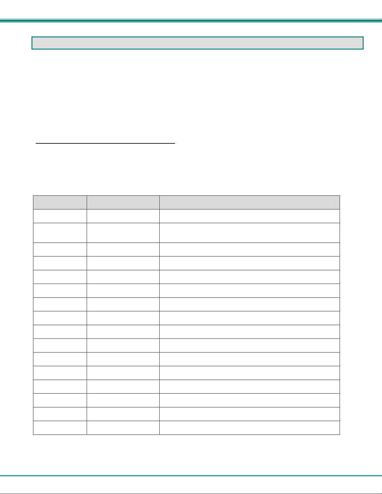
The Telnet Interface enables the user to control the switch using telnet client through an Ethernet connection. The telnet server
listens on ports 2000 and 2005. Port 2000 is for an operator telnet session while port 2005 (must be enabled) is intended for a
software control type session (see page 21). For operator telnet control using the telnet interface and the current IP address,
type the following in a command shell:
telnet 192.168.1.30 2000
The VEEMUX will prompt the user for a password. The user must enter the password followed by <Enter>.
The factory default password is "admin".
With a proper password sent the VEEMUX will respond with:
Password Successful
Connection Established
The following commands are now available:
Command Reply Description
H(elp) or
h(elp)
CP
CS nn,mm *<CR> Connect One Output (User Port) To Input (Video source)
Displays the list of
commands
User is prompted to
introduce the password
twice
Help
Change password
CA nn *<CR> Connect All Outputs To Input
RO nn *<CR>mm<CR>
CC nn *<CR>nn<CR>
RC nn *<CR>nn<CR>
CB nn *<CR>
RS *<CR> Reset Unit
RV 00 *<CR>string\0<CR> Read NTI Version String
RU *<CR>nn,mm<CR>
Ss nn,dwt *<CR>
Gs nn
Sa nn,mm *<CR> Set scan list of individual output nn to all inputs mm
Sc nn *<CR> Clear scan list of individual output nn
S+ nn,mm *<CR> Add input mm to Scan List of output nn
*<CR>
dwt<CR>
Read Connection For Output.
Returns the number of the input (mm) connected to output nn
Save Matrix Connections Into Memory Bank nn
nn should be between 00 and 99
Restore Matrix Connections From Memory Bank nn
nn should be between 00 and 99
Change baud rate of serial line, nn=12(00),24(00),48(00),96(00)
Factory default is 9,600.
Read Unit Size
Returns the number of inputs(nn) and the number of outputs (mm)
Set value of Scan Mode dwell time (see pg. 8) for specific Output (nn)
dwt = 000-255 (seconds) 000= disable Scan Mode
Read set Scan Mode dwell time value (dwt) for specific Output (nn) in
seconds (see also "Scan Mode" on page 8)
13
Page 18
NTI VEEMUX VIDEO MATRIX SWITCH
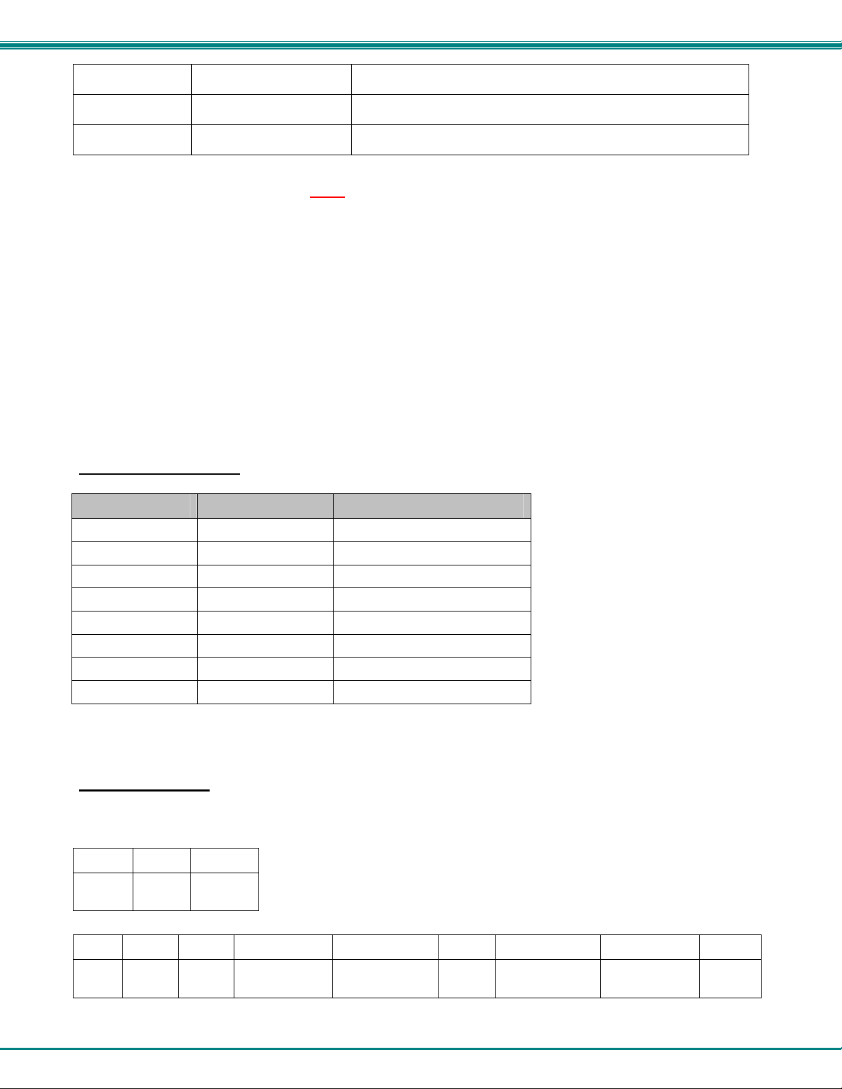
S- nn,mm *<CR> Remove input mm from Scan List of output nn
Sx nn
<Ctrl>-<X>
(see note 4 below)
Notes:
1. The commands must be typed exactly as shown in the chart. The commands are case sensitive.
2. If a mistake is made, the user must backspace to the beginning and completely retype the command.
3. If a command is sent that the VEEMUX does not recognize or exceeds the configuration of the switch, the
reply "?" may be received. Check the command syntax and try again.
4. To quit the telnet session, press the keyboard keys <Ctrl><X>.
*<CR>oooxoxxxooooxxx<
CR>
Good Bye.
Connection to host lost.
Display the Scan List of output nn (o=skip x=don't skip)
Quit telnet session
Telnet Interface-Port 2005
Legend: (All numbers must be two digits)
OP : Output Port (01-MAXOUTPUTS)
IP : Input Port (01-MAXINPUTS)
<CR> : Carriage Return (Hex 0xD)
Command Summary
Command String Good Response Description
RU<CR> ru OP,IP<CR> Read unit size
RO OP<CR> pc OP,IP<CR> Read connection for OP
CS OP,IP<CR> *<CR> Connect OP to IP
CA IP<CR> *<CR> Connect all outputs to IP
SS 01<CR> *<CR> Enable auto-status mode
SS 00<CR> *<CR> Disable auto-status mode
SX<CR> See details Examine connections
XX<CR> *<CR> Close connection
A <CR> (carriage return, 0x0D) is considered to be the end of the command string. If a string exceeds 16 characters, an end of
string will be inserted automatically to avoid buffer overflow. An eventual <LF> (line feed, new line, 0x0A) after a <CR> will be
ignored. A bad string will always be responded to with the ASCII character ‘?’ followed by a <CR>.
Command Detail
RU-Read Unit Size
Command:
Byte 1 Byte2 Byte3
‘R’
(0x52)
Response:
‘U’
(0x55)
<CR>
(0x0D)
Byte 1 Byte 2 Byte 3 Byte 4 Byte 5 Byte 6 Byte 7 Byte 8 Byte 9
‘r’
(0x72)
This command will read the size of the unit. The response returns the number of inputs and the number of outputs in two-digit,
ASCII code format. If the numbers are smaller than 10, the 1st digit is ‘0’.
‘u’
(0x75)
Space
(0x20)
Output – 1st digit
(0x30…0x32)
Output-2nd digit
(0x30…0x39)
‘,’
(0x2C)
14
Input – 1st digit
(0x30…0x32)
Input – 2nd digit
(0x30…0x39)
<CR>
(0x0D)
Page 19
NTI VEEMUX VIDEO MATRIX SWITCH
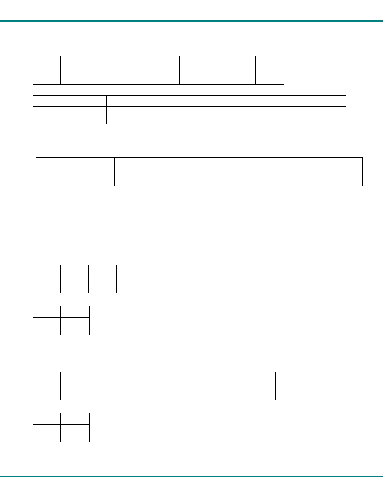
RO-Read Connection for Output Port
Command:
Byte 1 Byte 2 Byte 3 Byte 4 Byte 5 Byte 6
‘R’
(0x52)
Response:
‘O’
(0x4F)
Space
(0x20)
Output – 1st digit
(0x30…0x32)
Output – 2nd digit
(0x30…0x39)
<CR>
(0x0D)
Byte 1 Byte 2 Byte 3 Byte 4 Byte 5 Byte 6 Byte 7 Byte 8 Byte 9
‘p’
(0x70)
This command will read the connection of an output port. The response returns the output port that is connected to the input port.
‘c’
(0x63)
Space
(0x20)
Output – 1st digit
(0x30…0x32)
Output-2nd digit
(0x30…0x39)
‘,’
(0x2C)
Input – 1st digit
(0x30…0x32)
Input – 2nd digit
(0x30…0x39)
<CR>
(0x0D)
CS- Connect Output Port to Input Port
Command:
Byte 1 Byte 2 Byte 3 Byte 4 Byte 5 Byte 6 Byte 7 Byte 8 Byte 9
‘C’
(0x43)
Response:
‘S’
(0x53)
Byte 1 Byte 2
Space
(0x20)
Output – 1st digit
(0x30…0x32)
Output – 2nd digit
(0x30…0x39)
(0x2C)
‘,’
Input –1st digit
(0x30…0x32)
Input –2nd digit
(0x30…0x39)
<CR>
(0x0D)
‘∗’
(0x2A)
This command connects the specified input port to the specified output port.
<CR>
(0x0D)
CA- Connect All Output Ports to Input Port
Command:
Byte 1 Byte 2 Byte 3 Byte 4 Byte 5 Byte 6
‘C’
(0x43)
Response:
‘A’
(0x41)
Space
(0x20)
Input – 1st digit
(0x30…0x32)
Input - 2nd digit
(0x30…0x39)
<CR>
(0x0D)
Byte 1 Byte 2
‘∗’
(0x2A)
This command connects all output ports to the specified input port.
<CR>
(0x0D)
SS_01- Enable Auto Status Mode
Command:
Byte 1 Byte 2 Byte 3 Byte 4 Byte 5 Byte 6
‘S’
(0x53)
Response:
Byte 1 Byte 2
‘S’
(0x53)
Space
(0x20)
‘0’
(0x30)
‘1’
(0x31)
<CR>
(0x0D)
‘∗’
(0x2A)
Auto status mode is disabled by default whenever the connection is established, and this command must be entered to enable it.
When auto status mode is enabled, a message will be sent whenever an input/output connection changes from any source. The
format of this message is given in the table below. The first two numeric digits are the output port number and the two after the
colon are the number of the input port that is now connected to it.
<CR>
(0x0D)
15
Page 20
NTI VEEMUX VIDEO MATRIX SWITCH
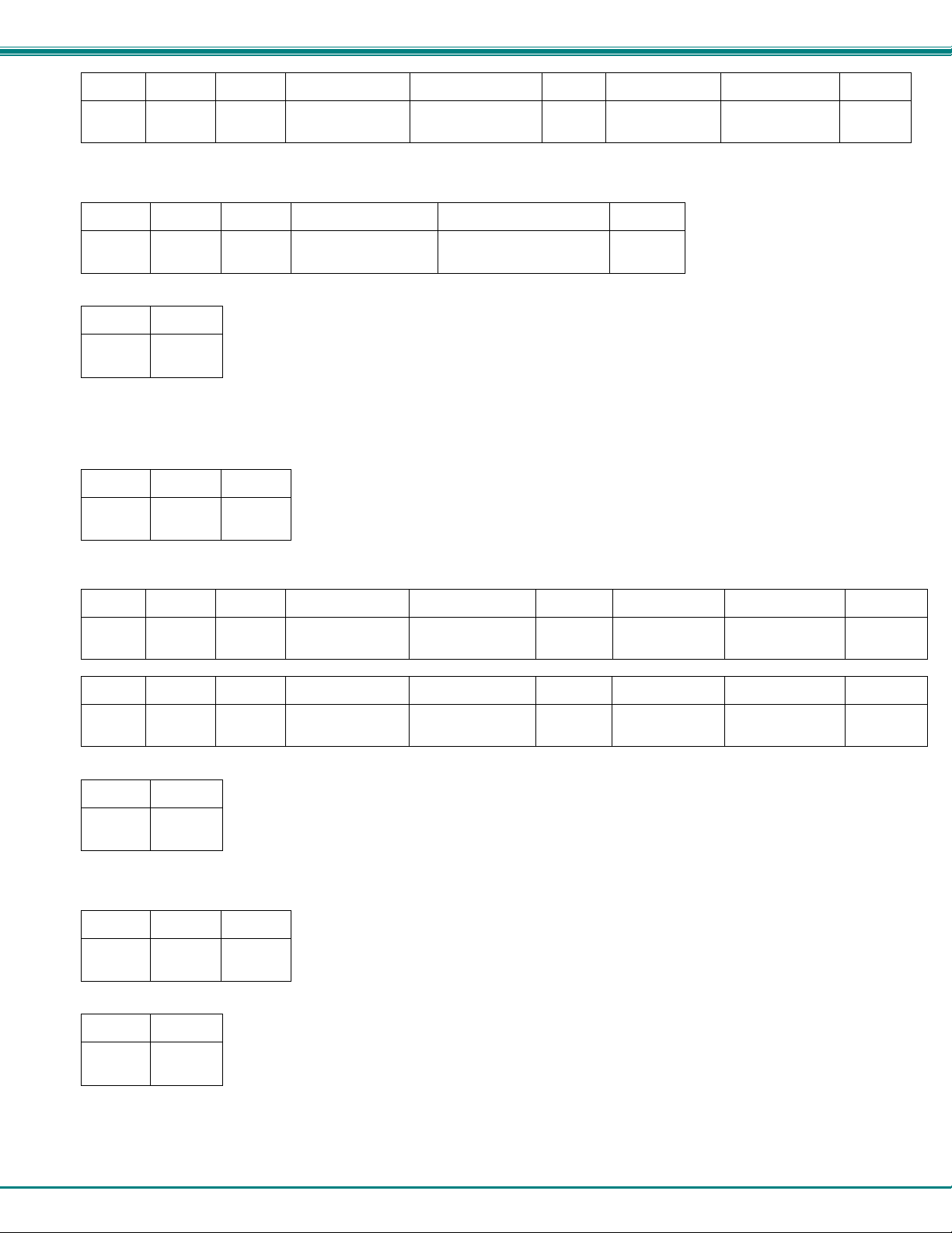
Byte 1 Byte 2 Byte 3 Byte 4 Byte 5 Byte 6 Byte 7 Byte 8 Byte 9
‘p’
(0x70)
‘c’
(0x63)
Space
(0x20)
Output – 1st digit
(0x30…0x32)
Output – 2nd digit
(0x30…0x39)
‘:’
(0x3A)
Input – 1st digit
(0x30…0x32)
Input – 2nd digit
(0x30…0x39)
<CR>
(0x0D)
SS_00- Disable Auto Status Mode
Command:
Byte 1 Byte 2 Byte 3 Byte 4 Byte 5 Byte 6
‘S’
(0x53)
Response:
‘S’
(0x53)
Space
(0x20)
‘0’
(0x30)
‘0’
(0x30)
<CR>
(0x0D)
Byte 1 Byte 2
‘∗’
(0x2A)
This command disables auto status mode.
<CR>
(0x0D)
SX- Examine connections
Command:
Byte 1 Byte 2 Byte 3
‘S’
(0x53)
Response:
Multiple lines, one line for each output:
Byte 1 Byte 2 Byte 3 Byte 4 Byte 5 Byte 6 Byte 7 Byte 8 Byte 9
‘p’
(0x70)
Byte 1 Byte 2 Byte 3 Byte 4 Byte 5 Byte 6 Byte 7 Byte 8 Byte 9
‘p’
(0x70)
Last line:
Byte 1 Byte 2
‘X’
(0x58)
‘c’
(0x63)
‘c’
(0x63)
<CR>
(0x0D)
Space
(0x20)
Space
(0x20)
Output – 1st digit
(0x30…0x32)
Output – 1st digit
(0x30…0x32)
Output – 2nd digit
(0x30…0x39)
Output – 2nd digit
(0x30…0x39)
‘:’
(0x3A)
‘:’
(0x3A)
Input – 1st digit
(0x30…0x32)
Input – 1st digit
(0x30…0x32)
Input – 2nd digit
(0x30…0x39)
Input – 2nd digit
(0x30…0x39)
<CR>
(0x0D)
<CR>
(0x0D)
‘∗’
(0x2A)
<CR>
(0x0D)
Terminate telnet session
Command:
Byte 1 Byte 2 Byte 3
‘X’
(0x58)
Response:
Byte 1 Byte 2
‘∗’
(0x2A)
The unit will respond with ‘*’<CR> and close the connection, terminating the telnet session. The unit is then available for future
connections.
‘X’
(0x58)
<CR>
(0x0D)
<CR>
(0x0D)
16
Page 21
NTI VEEMUX VIDEO MATRIX SWITCH
Web Interface
A user may control the connections of the VEEMUX using a Web Interface via any web browser (see page 1 for web supported
browsers). With the VEEMUX connected to a LAN through an Ethernet cable, a user can access the web interface controls inside
the VEEMUX.
FYI: To quickly locate a VEEMUX on the LAN and edit the IP address settings, use the Device Discovery Tool (page 26).
To access the web interface, type the current IP address into the address bar of the web browser.
Address
To open a SSL-encrypted connection, type:
Address
You will be prompted to accept a certificate. Accept the NTI certificate.
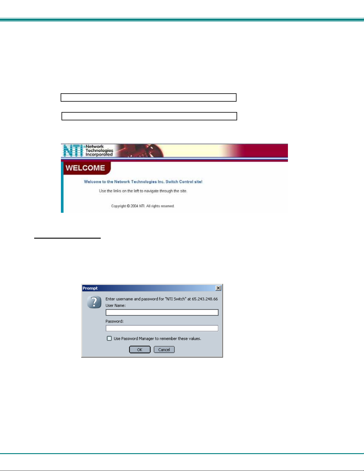
A "Welcome Page" will appear.
Figure 7- Web interface Welcome page
http://192.168.1.30
https://192.168.1.30
Enter the Password
Click on a link to the left to be prompted for a username and password. To change the password, see page 24.
User Name = Administrator (upper case letter for "A" only)
Password = admin (lower case letters only)
Note: The browser must be configured to
accept cookies in order for the user to
successfully make use of the web interface.
Figure 8- Web interface Login Prompt
As described on the following pages, each link will enable different areas of control for the VEEMUX.
17
Page 22
NTI VEEMUX VIDEO MATRIX SWITCH
Video Switch Page
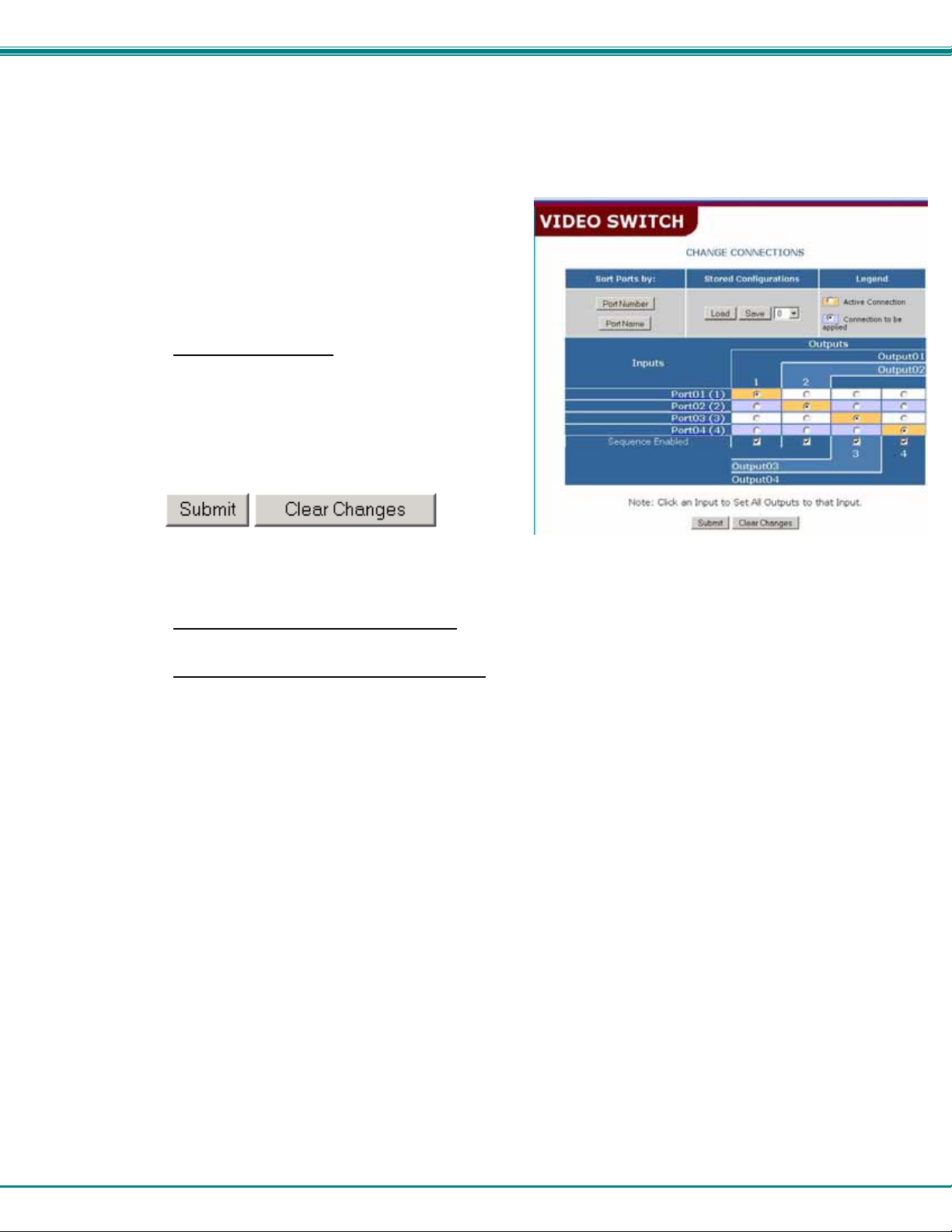
The Video Switch page (right) displays the active connections (shown in orange) and enables the user to control the
video connections of the VEEMUX. Up to 100 different connection configurations can be saved and later recalled
by any connection method. Output Scanning Sequences (page 21) for each output can also be enabled.
Note: If changes are made using the keypad (pg.7)
or by another user through the web interface, you
must refresh the screen using your browser to see
those changes.
Note: Configuration 0 will be automatically loaded
when the VEEMUX is powered up.
To change a connection
(square image with circle in the center) that intersects
the input and output columns. A black dot will be
placed in the circle to indicate the selection. Then
press the Submit button. The display will be reloaded
with the selections changed to orange to indicate they
are now active. Multiple connections can be changed
simultaneously.
, click on the radio button
Figure 9- Web interface Switch page
To quickly clear the selected radio buttons press the Clear Changes button. This will only work if the Submit
button has not already been pressed with the selections made.
To quickly connect all outputs to a single input
down list and press the Submit button.
Note: If radio buttons are selected in addition to using the "Set all Outputs to Input" option, the selections
made by the "Set all Outputs to Input" will take precedence when the Submit button is pressed. Selections
that conflict with it will be ignored.
Note: Scanning sequences that are enabled for an output through the web interface, either at the Video
Switch Page or at the Output Scanning Sequences page (page 21) will disable Scan Mode for that output as
configured through the LCD menu (page 8).
FYI: See page 22 for an example of using the Outputs Scanning Sequences feature.
, choose the desired input from the "Set all Outputs to Input" drop-
18
Page 23
NTI VEEMUX VIDEO MATRIX SWITCH
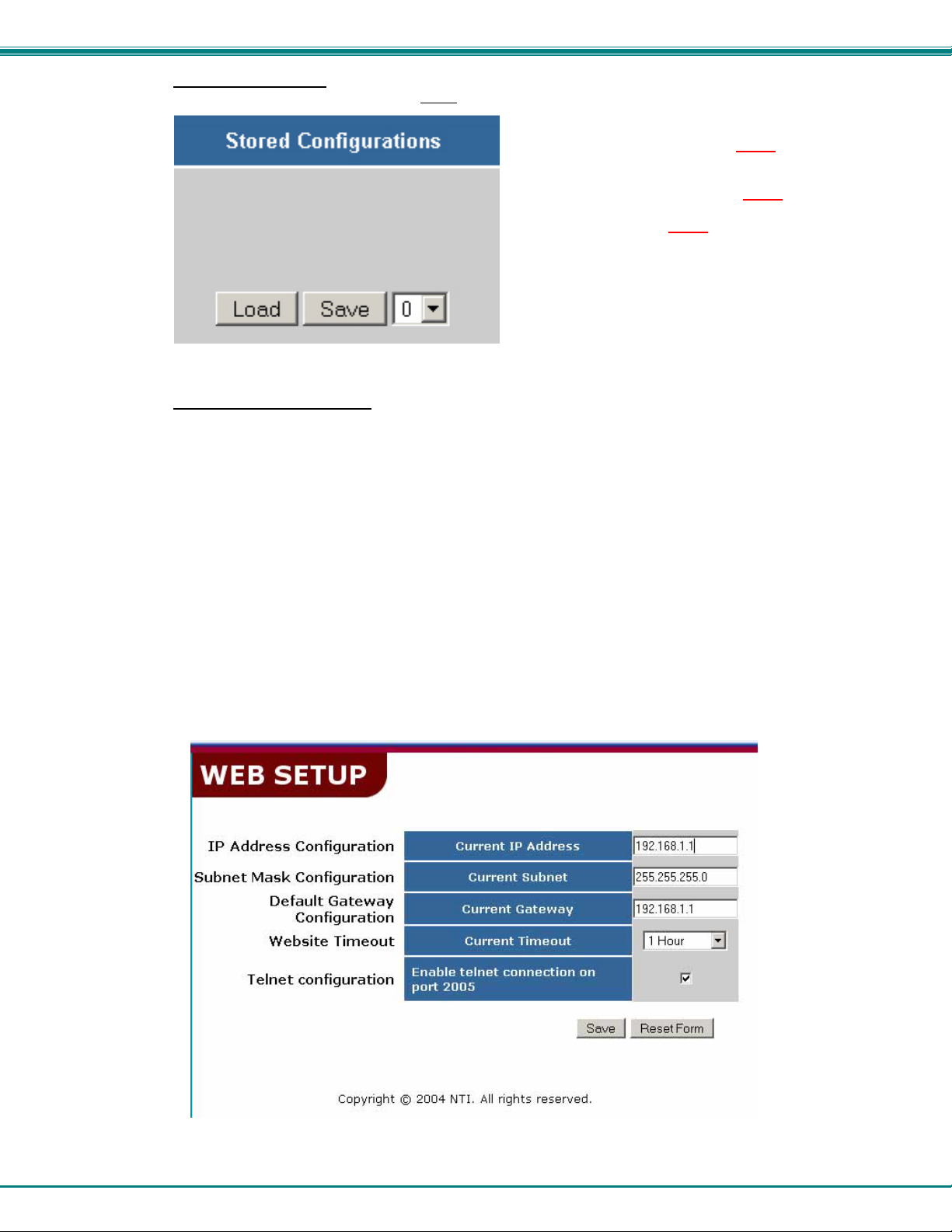
To save a configuraton, from the Stored Configurations user interface, use the drop-down list to select the
desired slot (numbers 0-99) to save the active
To load a saved configuration, from the Stored Configurations user interface, use the drop-down list to select the
desired configuration. Then press the Load button. The VEEMUX will make the connections and the screen will
refresh to show the connections associated with that configuration selection.
configuration into and press the Save button.
Note: This will save the currently active
the VEEMUX. If changes have been made in the web
interface without first pressing the Submit button, those
changes will not yet be part of the active
Note: If changes to the active configuration have been
made by another user prior to saving the current
connection selections, the changes made by the other
user will be saved as the configuration.
The webpage configuration that loads after a Save is the
configuration that was actually saved.
configuration on
configuration.
FYI: Configurations saved via the keypad (pg. 7) can be recalled through this interface, and vice versa. They are one in
the same.
Setup Pages
These settings enable the user to configure the VEEMUX web interface connection. This change will take a few
seconds and automatically redirect the user to the IP address specified.
Note: Since the webserver will be restarting all active connections will be logged out.
The Website Timeout option controls how long an inactive web connection will stay logged in.
Any change to the Website Timeout configuration takes effect immediately.
The “Telnet configuration” block enables the VEEMUX to receive commands on port 2005 in addition to port 2000.
For more on telnet use, see “Telnet Interface- Port 2000” on page 13.
Figure 10- Web interface Setup page
19
Page 24
NTI VEEMUX VIDEO MATRIX SWITCH
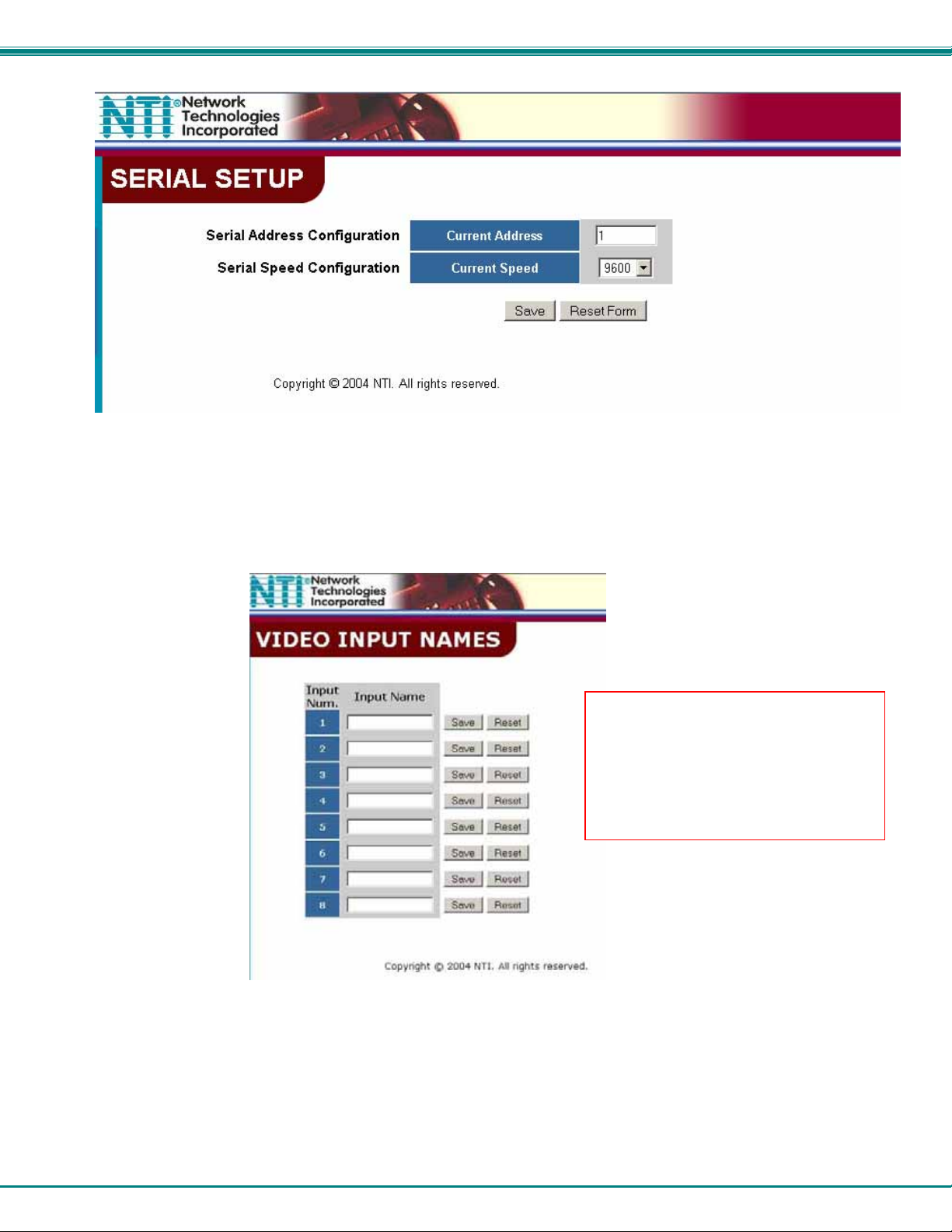
Figure 11- Web interface Serial Setup page
Changes to the Serial Address and Serial Speed (Fig. 11) do not require a reset and will take effect
immediately.
Video Input Names
Figure 12- Web interface Video Input Names page
The Video Input Names page enables the Administrator to change the name of the input ports displayed on the Video Switch
page. To change an Input Name, enter the name of the port for the desired input port number, and press Save.
Note: Only the changes to the port
directly to the left of the Save button will
be saved. All other changes to ports
without pressing the port's respective
Save button will be discarded. All port
names must be no more than 12
characters in length and only
alphanumeric characters may be used.
20
Page 25
NTI VEEMUX VIDEO MATRIX SWITCH
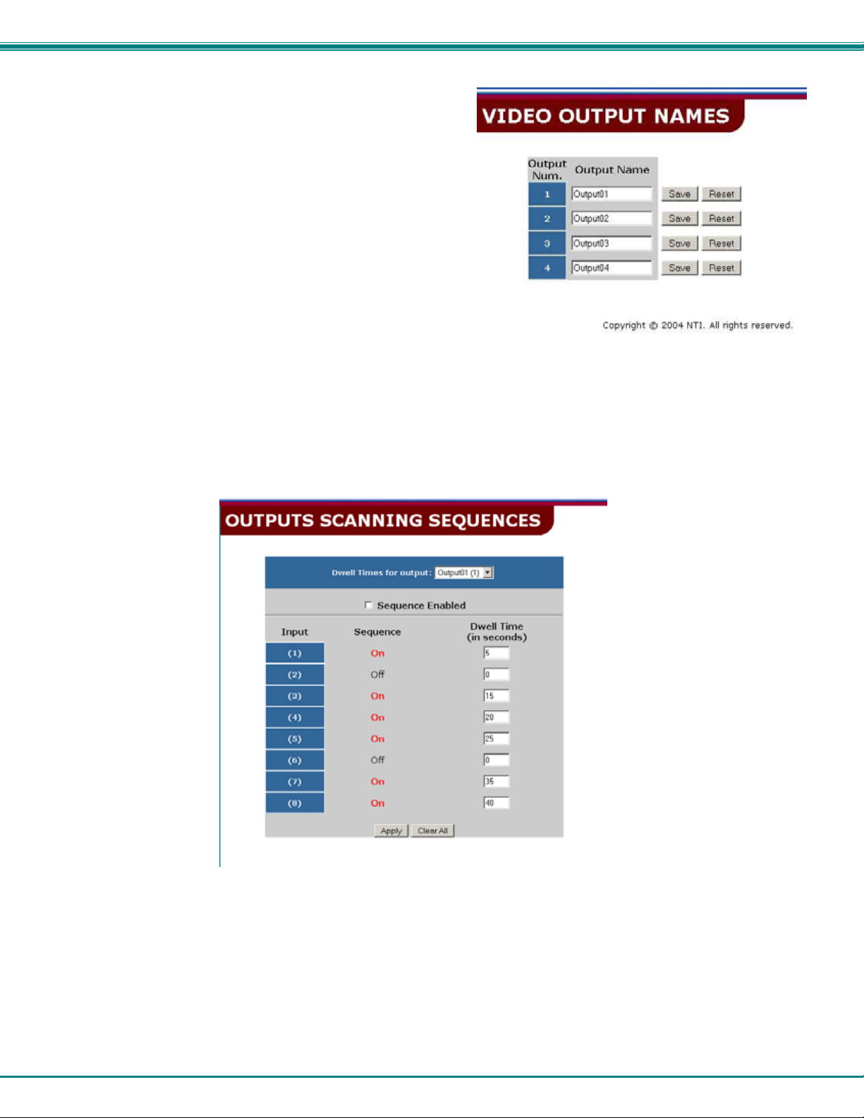
Output Names
From the Administration menu, the Output Names page can be
displayed. This page enables the Administrator to change the
names of the output ports displayed on the Switch page. To
change an Output Name, enter the name of the port for the
desired output port number, and press "Save".
Figure 13- Output Port Names
Outputs Scanning Sequences
Figure 14- Outputs Scanning Sequences page
The Outputs Scanning Sequences page displays the configuration of an automatic switching sequence from input (video source)
to input for each output (monitor).
The page displays:
output number being configured
the Scanning Sequence function status for that output
the Scan Mode status of each input (ON/OFF)
the length of time in seconds (dwell time) that each input will be viewed when connected
21
Page 26
NTI VEEMUX VIDEO MATRIX SWITCH
The output selection at the top of the page can be changed to any output to display the Scan Sequence Input selections and dwell
times for that output.
The inputs and the amount of time that each will be viewed (0-32000 seconds) can be set to cycle sequentially for each connected
output. If an input is set to 0 seconds, the sequence status will display “OFF”, and the input will be omitted from the scanning
sequence. To include an input in the sequence, enter a dwell time period from 1-32000 seconds, and press Apply.
To quickly clear all dwell time settings, press the Clear All button at the bottom of the page. All sequence settings will change to
“OFF” and all dwell time settings will change to 0.
To enable the scanning sequence for the output shown, place a checkmark in the “Sequence Enable” block.
Tip: To quickly enable the scan sequence for multiple outputs, use the “Sequence Enable” blocks found on the Switch
Page (page 18).
Note: If only 1 input is set to Sequence “ON”, then the output connection to that input will not change when the Scanning
Sequence is enabled.
Note: If the scanning sequence for an output is enabled through the web interface, then the Scan Mode for that output
as configured through the LCD menu (page 8) will be disabled.
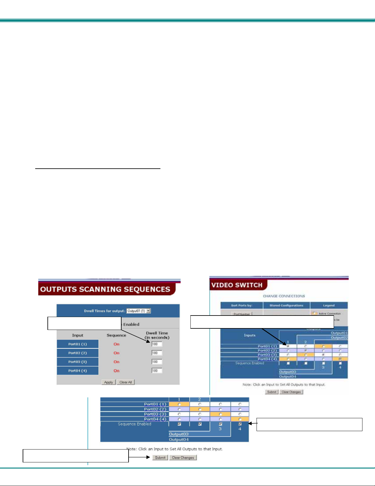
Example of using Outputs Scanning Sequences
Problem: A synchronous scan is desired for all outputs with a dwell time of 30 minutes per input, and no two outputs should be
looking at the same input at any given time.
Solution:
1. Set the dwell time for all inputs listed in each output at 180 seconds (30 minutes). Press “Apply”.
2. Go to the Video Switch page (page 18) and set each output to an input of the same number (1 to 1, 2 to 2, 3 to 3, etc..).
Click on “Submit” at the bottom of the Video Switch Page to submit selections and establish a connection and starting
point for the scanning sequence. (Blocks shown in yellow in the third image indicate connections made.)
3. Click on the “Sequence Enable” box for each output (from the Video Switch Page).
4. Click on “Submit” again to begin the scanning sequence for each output.
From the moment the configuration is submitted, a synchronous scan will begin on all outputs. Each output will connect to its
respective input for 30 minutes. After 30 minutes, the outputs will each switch to the next consecutive input and remain
connected for 30 minutes. This cycle will continue indefinitely until sequencing is disabled.
Step 1- setup dwell times
Step 4- Click on “Submit” to begin
Step 2- setup starting point for scan and click “Submit”
Step 3- enable the scanning sequence
22
Page 27
NTI VEEMUX VIDEO MATRIX SWITCH
Update Firmware
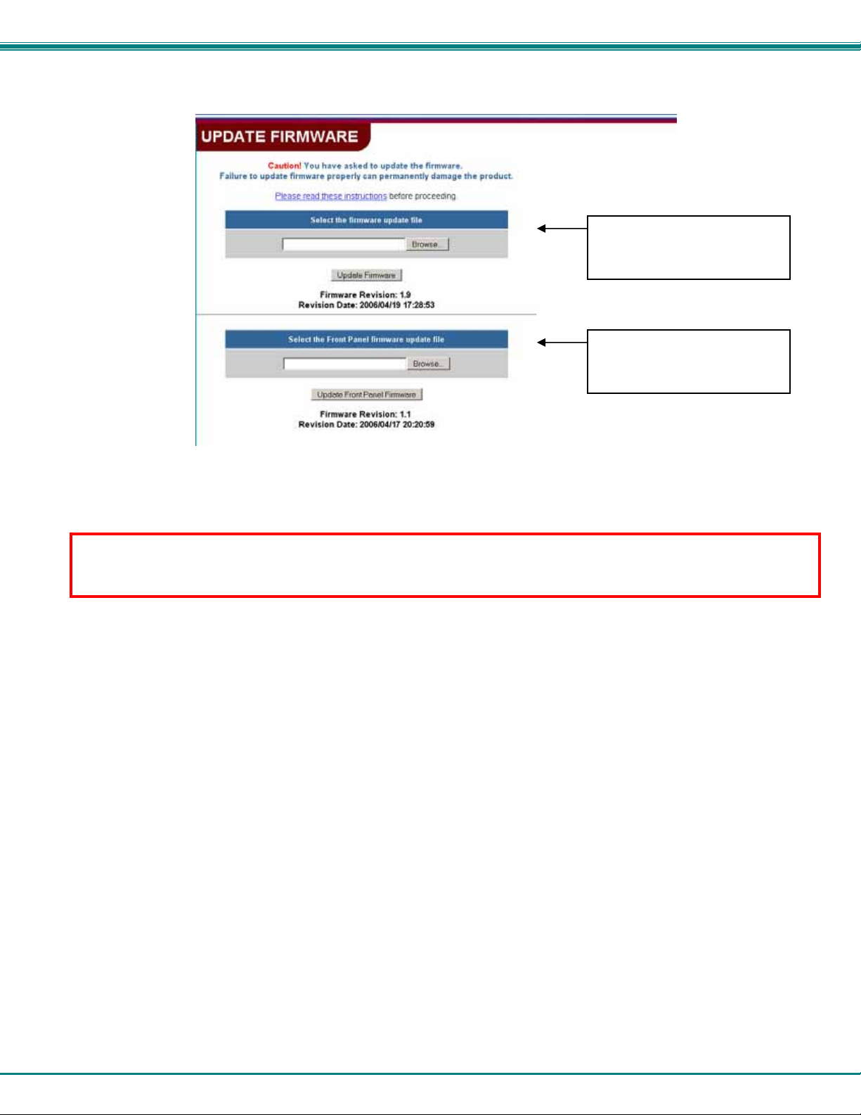
Figure 15- Web interface Update Firmware page
The Update Firmware page (located in the main menu under "ADMINISTRATION") shows the current version of the
firmware for the Web interface (Fig-15-upper) and for the Front panel (Fig-15-lower) and enables the Administrator to update the
firmware of the VEEMUX.
WARNING: Failure to carefully follow these directions can permanently damage the VEEMUX. Please read these
directions in full before continuing. Do not, under any circumstances, reset or power-down the VEEMUX while the
firmware is being updated. Do not attempt to update the firmware if a power-failure is likely.
Note: The Firmware can only be updated from the non-secure (http) website. If you attempt to access this page from the
secure (https) website, you will be automatically redirected to the non-secure site.
To update the firmware:
1. Contact NTI for the latest firmware file (see Fig. 15) and copy it to your computer.
2. On the Update Firmware page, in the section to be updated, browse to the firmware file.
3. Press Update Firmware (for the Ethernet Control) or Update Front Panel Firmware (for the LCD).
Note: If an update is attempted using the wrong firmware for the section an error message will be received. No update
will occur.
4. Wait for the following message to appear (may take several minutes):
Upload Succeeded
Flash of new image completed:
The system will automatically restart.
5. The VEEMUX will restart itself in 10 seconds, logging out all connections. After approximately 40 seconds,
the VEEMUX will be ready to resume operation.
If a message appears stating that the Upload has failed, or that a non-fatal error has occurred:
1. Ensure that the file being uploaded is the NTI firmware file.
2. Repeat the process from step 2 above.
Note: The following message does not indicate that damage to the product has occurred.
If a message appears stating that there has been a fatal error:
1. DO NOT RESET OR POWER-DOWN THE VEEMUX.
2. Repeat the update process from the first step 2 above.
3. If you get another Fatal Error message, call NTI tech-support at 1-800-742-8324 or 330-
562-7070.
FYI: The VEEMUX should continue to run normally unless it is reset. However, damage may have occurred
to the web server firmware that will prevent the product from starting up correctly.
23
For updating the Ethernet
Control, use this section and
insert the file v1_x.bin
For updating the Front Panel
LCD, use this section and insert
the file rmtlcd_va_1_x. hex
Page 28
NTI VEEMUX VIDEO MATRIX SWITCH
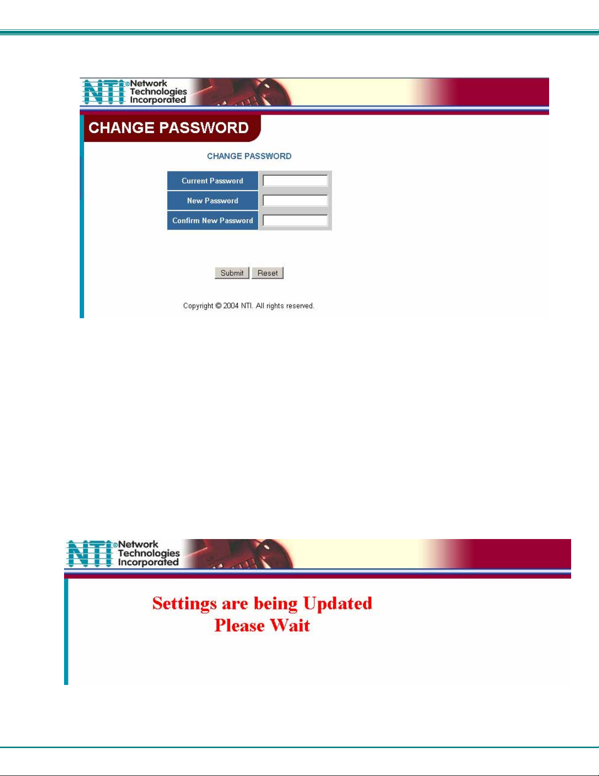
Change Password Page
Figure 16- Web interface Password page
Use this page to change the password for accessing the web interface. (This password is also used for the telnet
interface.) Be sure to make note of the new password exactly as it is case sensitive. The password must be
between 5 and 16 characters in length and can be alphabetical or numeric.
Help Page
This page explains the purpose of each of the other pages in the VEEMUX web interface.
Update Web Server
Click on this selection to globally update the Web Server to any settings that have been changed though Telnet, the
RS232 interface, or via the front panel of the VEEMUX. All users presently connected will be disconnected and must log
back in after using this command.
Figure 17- Updating the Web Server
24
Page 29
NTI VEEMUX VIDEO MATRIX SWITCH
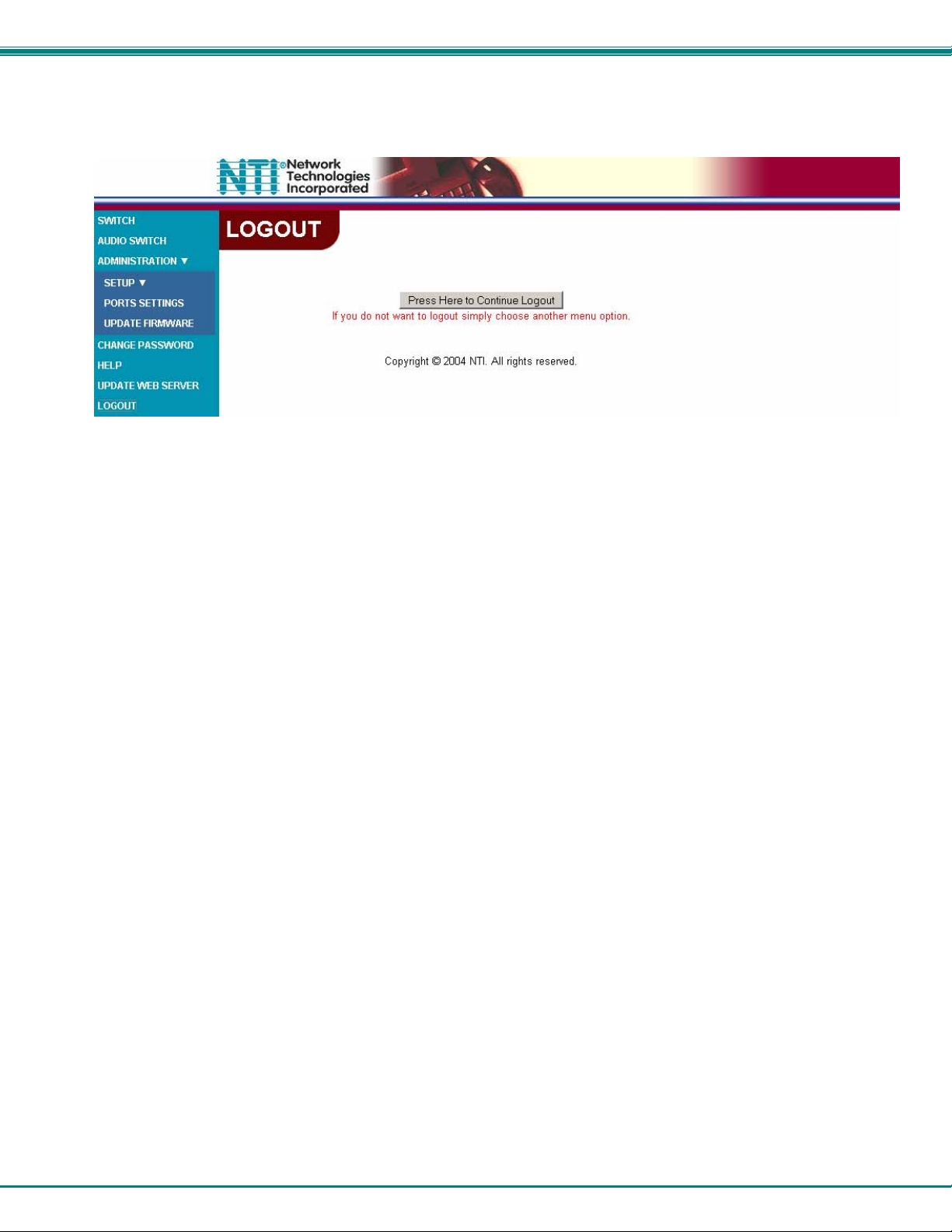
Logout Page
Figure 18- Web interface Logout page
This page will enable the user to end the session and close the web interface connection. Click on the "Press Here
to Continue Logout" button to exit the VEEMUX web interface.
Note: The connection will timeout automatically after a preset period of inactivity, configurable on the Web Setup
page.
25
Page 30
NTI VEEMUX VIDEO MATRIX SWITCH
DEVICE DISCOVERY TOOL
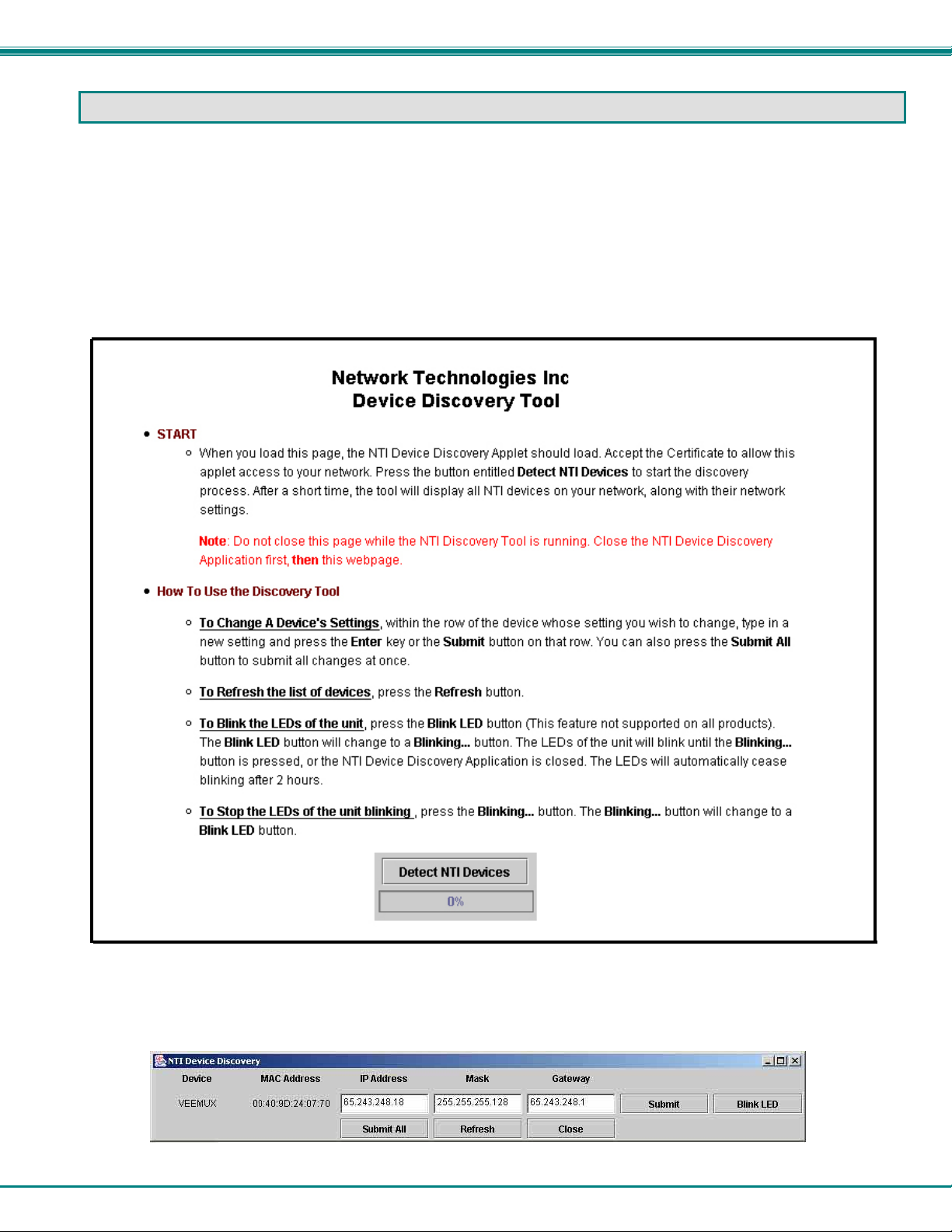
In order to easily locate the VEEMUX on a network, or to change network settings, the NTI Device Discovery Tool may be used.
A link to the Discovery Tool is provided on the web page that appears when you insert the instruction manual CD provided into
your CD ROM drive. Click on the link or browse the CD and click on the file discover.html . This will open your browser and
display the Device Discovery Tool page.
Note: The Discovery Tool requires the Java Runtime Environment to operate. A link to the web page from which it can
be downloaded and installed is provided on the CD.
Note: The computer using the Discovery Tool and the VEEMUX must be connected to the same physical network in order
for the Device Discovery Tool to work.
Figure 19- Device Discovery Tool page
Use the Device Discovery Tool to display all NTI VEEMUXs on your network, along with their network settings. Follow the
instructions on the Device Discovery Tool page to use the tool and to change the device settings if so desired.
26
Page 31
NTI VEEMUX VIDEO MATRIX SWITCH
INFRARED CONTROL
(Optional)
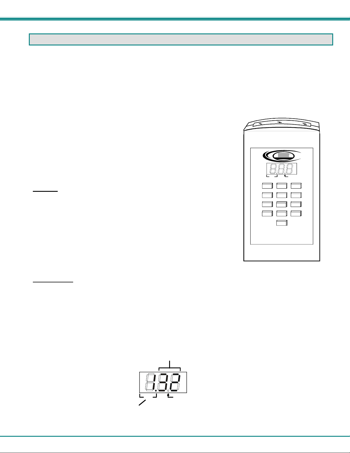
The IRT-64X32 (or IRT) is an infrared remote transmitter that enables the user to control up to four (4) NTI VEEMUX Video Matrix
switches via an infrared receiver from up to 50 feet away (with an unobstructed view). The IRT is battery-powered and always
ready to use. The IRT will have a blank display unless an action is being selected by the user. The IRT enables the user to
make connections between any input (video source) and any output (display device) on up to four (4) separate switches
.
Note: Multiple switches that are located close to each other and are to be individually controlled must be pre-configured
(by NTI) to be identified by the IRT as switches #1, #2, #3, or #4. Please ask your salesperson to have switches
configured accordingly at time of order. Unless otherwise specified, by default, all IRT-enabled switches will be
configured as switch #1.
Materials included:
• IRT-64X32 Infrared Remote Transmitter for video matrix switches
• (2) AA Cell Batteries- installed
NTI
Network Technologies Inc
R
Features And Functions
Keypad
¾ Buttons Numbered 0-9 – Used for port selection
¾ OUT – Pressed to validate and transmit the Output selection
¾ IN – Pressed to validate and transmit the Input selection
¾ SYS – Pressed to choose the switch to be controlled or to configure the maximum
number of inputs/outputs
SW
12 3
45 6
78 9
OUT IN
Lo Batt
0
SYS
IRT-6 4X32
LCD Display
¾ The first digit of the LCD will display the number of the switch to be controlled followed by the decimal point. This way the
user will always know which switch will be effected by the IRT.
¾ The last two digits in the LCD represent 1) the desired input or output port to be connected or 2) the desired switch to be
controlled when changing switches.
¾ The "Lo Batt" decimal point will illuminate when the user should change the batteries.
¾ The LCD will automatically power-down after 30 seconds of non-use and power-up with the press of any button.
Represents switch to be controlled
Represents Input or
Output
Lo BattSW
27
Page 32
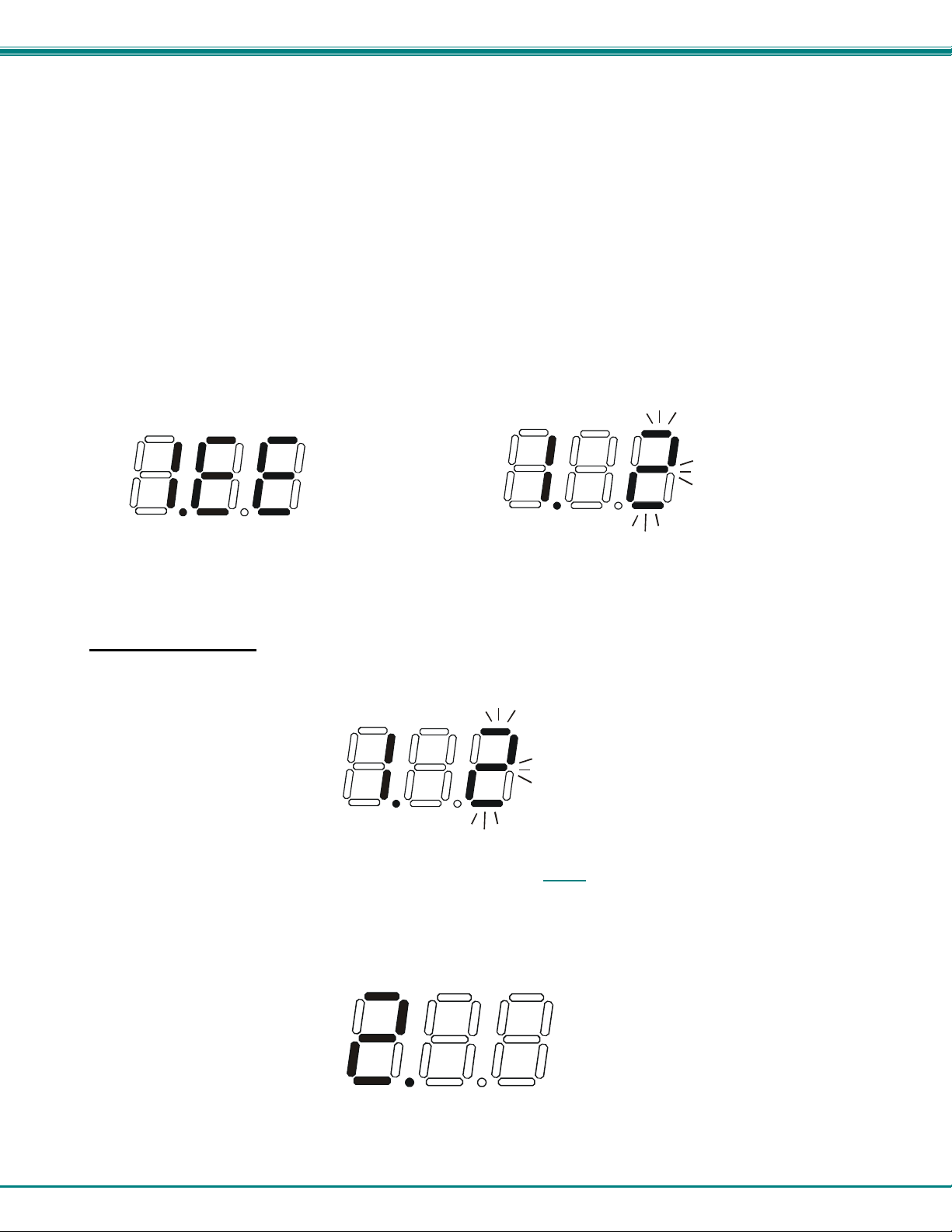
NTI VEEMUX VIDEO MATRIX SWITCH
How To Use The IRT
The IRT-64X32 enables the user to control the connections of up to 32 input ports and 16 output ports on up to four (4) separate
NTI video matrix switches. When any key is pressed, the IRT will power ON. A number key should always be pressed first
unless a change to the configuration is desired (see "Set Configuration" on page 30). When a number key is pressed the LCD
will display that number blinking. What to press next depends on what action is desired;
• change the switch to be controlled
• change the output port
• change the input port
Note: The user must always change or confirm the output port first and the input port second
If the "SYS", "IN" or "OUT" key is pressed first, the LCD will display the current switch followed by the decimal point and an error
signal "EE". The error signal will display because there is no number to be displayed. A number key must always be pressed
before a "SYS", "IN" or "OUT" key is pressed.
Exception: The "SYS" key is pressed first when setting the configuration. (See page 30)
Power ON with SYS, IN or OUT keys Power ON with "2" key
Change the Switch
Press the number of the switch to be controlled. The number selected will be blinking in the last digit.
FYI: If the user realizes that an invalid number has been introduced before
buttons, a correction can be made by pressing the correct number. If the correct number is a single digit, it must be
preceded by a "0" to make the correction.
Press the "SYS" key. The blinking number will become blank and the switch number will update.
Note: If the number entered is larger than 4, when the "SYS" key is pressed the LCD will display the current switch and
the error signal "EE".
28
pressing either the "SYS", "IN", or "OUT"
Page 33
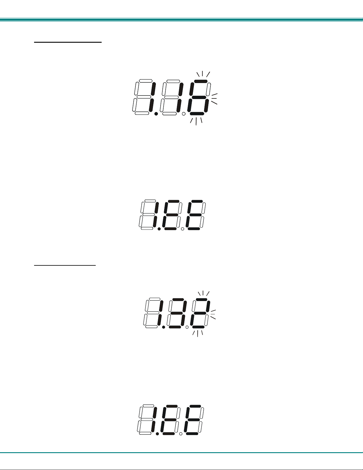
NTI VEEMUX VIDEO MATRIX SWITCH
Change Output Port
Press the desired port number. If there is no change in the desired output port, the output port must still be selected. As the
digits are selected, the last number entered will blink. The LCD will also display the current switch number followed by the
decimal point.
With the desired port number selected, point the IRT at the switch/receiver and press the "OUT" button to transmit the selection
and make the change. The blinking number in the LCD will stop blinking. An LED on the receiver will illuminate.
FYI: If the switch did not receive the data the LED will not illuminate. The user can re-send the same data by pressing
the "OUT" button again. The LED at the receiver will illuminate to indicate a completed transmission from the IRT..
Note: If the number introduced is larger than the maximum number of outputs the IRT is configured for, then once the
"OUT" key is pressed the LCD will display the current switch and the error signal "EE".
Change Input Port
Press the desired port number. As the digits are selected, the last number entered will blink. The LCD will also display the
current switch number followed by the decimal point.
With the desired port number selected, point the IRT at the switch/receiver and press the "IN" button to transmit the selection and
make the change. The blinking number in the LCD will stop blinking. The LED at the receiver will go OFF.
FYI: If the switch did not receive the data the LED will not go OFF. The user can re-send the same data by pressing the
"IN" button again. The illuminated LED on the receiver will go OFF when the received data is complete.
Note: If the number introduced is larger than the maximum number of inputs that the IRT is configured to control, then
once the "IN" key is pressed the LCD will display the current switch and the error signal "EE".
29
Page 34

NTI VEEMUX VIDEO MATRIX SWITCH
Set Configuration
The IRT-64x32 factory default setting is 32 inputs and 16 outputs. When the batteries are changed the setting will return to the
default value. At the default setting the IRT has the ability control any matrix switch with up to 32 inputs and 16 outputs without
changing the configuration. However, when controlling smaller switches without changing the configuration it is up to the user to
press valid number(s). To avoid confusion, it is recommended to configure the IRT to communicate with the largest switch to be
controlled.
To change the maximum number of inputs or outputs:
1. From power-down state (blank LCD) press and hold the "SYS" button for at least 3 seconds. The LCD will first display an
error message but after 3 seconds the letter "c" will display:
2. Enter the number of inputs or outputs. As the digits are entered, they will be displayed and the last one entered will blink.
Note: Only the inputs OR the outputs may be configured each time the configuration function is used. To perform
another configuration operation the user must start again at "Set Configuration" step 1.
3. Accept the choice by pressing the "IN" button for setting inputs, or the "OUT" button for setting the outputs. The LCD will not
blink anymore and will display “i” (for inputs) or "o" (for outputs) and the number.
Notes:
- The maximum number of inputs and outputs that can be entered is 32 and 16 respectively. If the user introduces a
number larger, the display will show an error signal ("c.EE") and the maximum number will remain at the last valid
value configured.
- If more than one switch is being controlled, the IRT should be configured for the largest switch. It is up to the user
to introduce valid numbers to the smaller switches when making selections.
30
Page 35
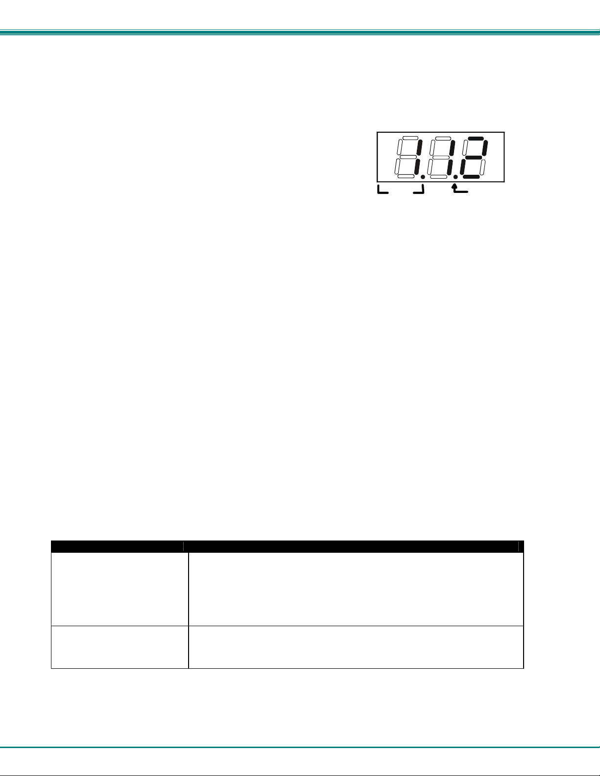
NTI VEEMUX VIDEO MATRIX SWITCH
Battery Replacement
The IRT has a low-battery indicator to let the user know when it is time to change the batteries. The right-hand decimal point in
the LCD display will illuminate (see illustration below). This will stay illuminated while the IRT is in use until the batteries are
changed or the battery charge is too low for the IRT to operate.
To Change The Batteries:
1. Remove slide cover on rear of unit.
2. Remove old batteries carefully.
3. Insert (2) new “AA” cell batteries.
4. Replace slide cover on unit.
SW
Lo Batt
5. Reset the configuration if a range other than the default setting is desired.
Specifications
• 50 feet maximum operating range between the transmitter and the front of the NTI switch / infrared
receiver.
Note: Line of sight between IRT and receiver must be unobstructed.
• Select up to 16 outputs
• Select up to 32 inputs
• Operates with (2) “AA” batteries.
• "Lo Batt" decimal point in LCD will illuminate to indicate a low battery when the battery voltage drops to approximately 2.25
volts.
IRT Troubleshooting
PROBLEM SOLUTION
IRT is not selecting output
IRT is not selecting input
• Check battery
• Make sure you are using the correct IRT for the switch. (Check model number
on the front of the IRT.)
• The IRT may be configured to control the wrong switch or the wrong size of
switch (see "Set Configuration" on page 30)
• Check battery
• The IRT may be configured to control the wrong switch or the wrong size of
switch (see "Set Configuration" on page 30)
31
Page 36
NTI VEEMUX VIDEO MATRIX SWITCH
DDC SUPPORT
(Optional)
DDC information allows the CPU to automatically select the optimal resolution for the monitor by receiving, at power up,
information from the monitor concerning its resolution specifications.
When DDC Support is installed, the DDC information is acquired from the monitor by the VEEMUX-A switch when the VEEMUX-A
is powered-up. A monitor with DDC support must be connected to MONITOR 1 for this to occur. The DDC information will
be made available at every CPU port.
The DDC information can also be acquired by pressing the DDC button located on the front of the switch. This button allows the
monitor configuration to be changed without powering down the switch.
Notes:
1. All monitors connected to the VEEMUX-A switch with DDC support must be able to support at least the maximum
resolution of the DDC monitor connected to '"MONITOR 1".
2. In order for the CPU to correctly receive the DDC information from the switch at boot-up, the switch must be
powered up before all attached CPUs.
32
Page 37
NTI VEEMUX VIDEO MATRIX SWITCH
RS232 UPGRADE OF THE FRONT PANEL LCD FIRMWARE
The firmware in the front panel LCD can be upgraded to include the latest features available using either the RS232 port
(below) or Ethernet Control (page 23). Follow the procedure below to use the RS232 method to update the Front Panel LCD
firmware in the VEEMUX. To prepare, first download the rmtlcd_va_1_x. hex file (x= the current firmware version) from
the NTI Video Matrix Switch website http://www.networktechinc.com/vmtx.html
The following will be needed:
1 PC running HyperTerminal (or other terminal program) equipped with a 9 pin or 25 pin serial port
o
o A VEEMUX made to use the Firmware Upgrade feature
o 1 serial cable wired straight through to connect your PC's serial port to the “RS232” port on the VEEMUX (see
cable specifications on page 35)
o A firmware file for a VEEMUX downloaded from www.networktechinc.com
Procedure:
1. Power OFF the VEEMUX.
2. Connect the null modem cable between the serial port on the PC and the “RS232” port on the VEEMUX.
.
3. Use HyperTerminal to prepare to connect to the VEEMUX (using settings 9600 baud, 8-N-1 no flow). Make sure
HyperTerminal has been configured for connection through the correct COM port on the PC.
4. With the HyperTerminal window open, hold the spacebar and apply power to the VEEMUX. A command menu and the
Command prompt (>) should appear.
Copyright 2006 Network Technologies Inc
Flash Loader Utility v1.0
H Display this help menu
C Clear flash
L Load flash with .hex file
Command>
Note: Commands are not case-sensitive (for example, 'h' or 'H' will execute the help command), and the <Enter> key
is not required to execute a command.
If the Flash Loader Utility menu does not appear, the VEEMUX you have may have been made prior to the release of
this product change. To verify this, with the VEEMUX powered ON, at the HyperTerminal window enter the following
command:
RV 01 (be sure to include the space)
The following revision string will appear:
$date: 2006/04/17
If the date shown is before
20:20:59 $$revision: 1.1 $$IN: 08 $$OUT: 04 $
2006/04/17, then the VEEMUX firmware cannot be upgraded using this procedure.
33
Page 38

NTI VEEMUX VIDEO MATRIX SWITCH
5. Press <L> to load the firmware (hex) file. This will prepare the file for transfer to the VEEMUX.
If the file fails to load, press the <C> key to clear the old firmware, and press <L> to load it again.
6. When the message “Start sending file via Xmodem protocol..”' appears, the VEEMUX is waiting for the Firmware file to
be uploaded.
A box or some other characters may be displayed repeatedly on the line below this message while the VEEMUX waits;
this is normal.
7. Click “Transfer” > “Send File...” from the HyperTerminal menu bar
8. Select “Xmodem” from the Protocol drop-down menu,
9. Click “Browse”. Go to the directory containing the firmware to load into the VEEMUX. Select to highlight the hex file,
click “Open”, then click “Send”.
10. A window will appear displaying information about the upload operation, including the upload process. It may take a few
seconds for the upload to begin.
DO NOT DISRUPT POWER while the firmware is uploading to the VEEMUX.
11. When the upload is completed, the command prompt will return. Power the VEEMUX OFF, then ON again. Upgrading is
complete, and the VEEMUX is ready to use.
34
Page 39
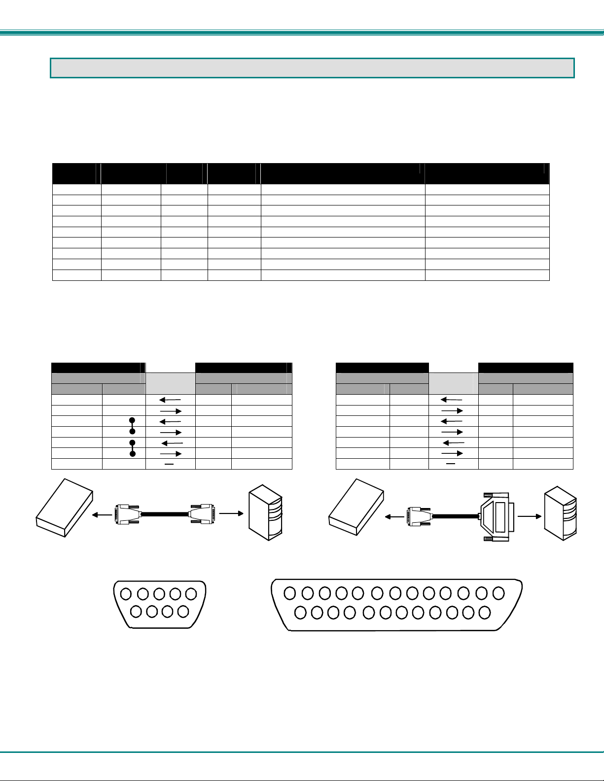
NTI VEEMUX VIDEO MATRIX SWITCH
RS232 CONNECTION CABLES
Pinout of RS232 port on VEEMUX
The VEEMUX RS232 serial port is a DB-9F (female) connector configured as a DCE (data communication equipment) port. The
RS232 port interface signals are listed below, including equivalent CCITT V.24 identification, and signal direction:
DB-9F
pin #
1 N/a N/a N/a No connection -2 TxD BA 103 Transmit Data Output
3 RxD BB 104 Receive Data Input
4 DSR CC 107 Data Set Ready Input
5 SG AB 102 Signal Ground –
6 DTR CD 108.2 Data Terminal Ready Output
7 CTS CB 106 Clear To Send Input
8 RTS CA 105 Request To Send Output
9 N/a N/a N/a No connection --
Common
name
EIA
name
CCITT
name
Function Direction
Specifications for Straight-Through Serial Cable for CPU Connection
VEEMUX to PS2 or SUN CPU (9 PIN) VEEMUX to MAC CPU (25 PIN)
VEEMUX PS/2 or SUN CPU VEEMUX MAC CPU
9 pin Signal 9 pin 9 pin Signal 25 pin
Function Pin # Direction Pin # Function
RxD 3 3 TxD RxD 3 2 TxD
TxD 2 2 RxD TxD 2 3 RxD
CTS 7 7 RTS CTS 7 4 RTS
RTS 8 8 CTS RTS 8 5 CTS
DSR 4 4 DTR DSR 4 20 DTR
DTR 6 6 DSR DTR 6 6 DSR
SG 5 5 SG SG 5 7 SG
VEEMUX
9 PIN
DTE
9 PIN
DTE
PS/2 or SUN CPU
1
2345
6
8
7
9
Mating Face
of a 9D Male
1
14 15
2
Function Pin # Direction Pin # Function
9 PIN
VEEMUX
345
18
17
16
6
19 20
DTE
89
7
21 22 23 24 25
10
25 PIN DTE
13
1211
Mating Face of DB25 Male
MAC CPU
35
Page 40
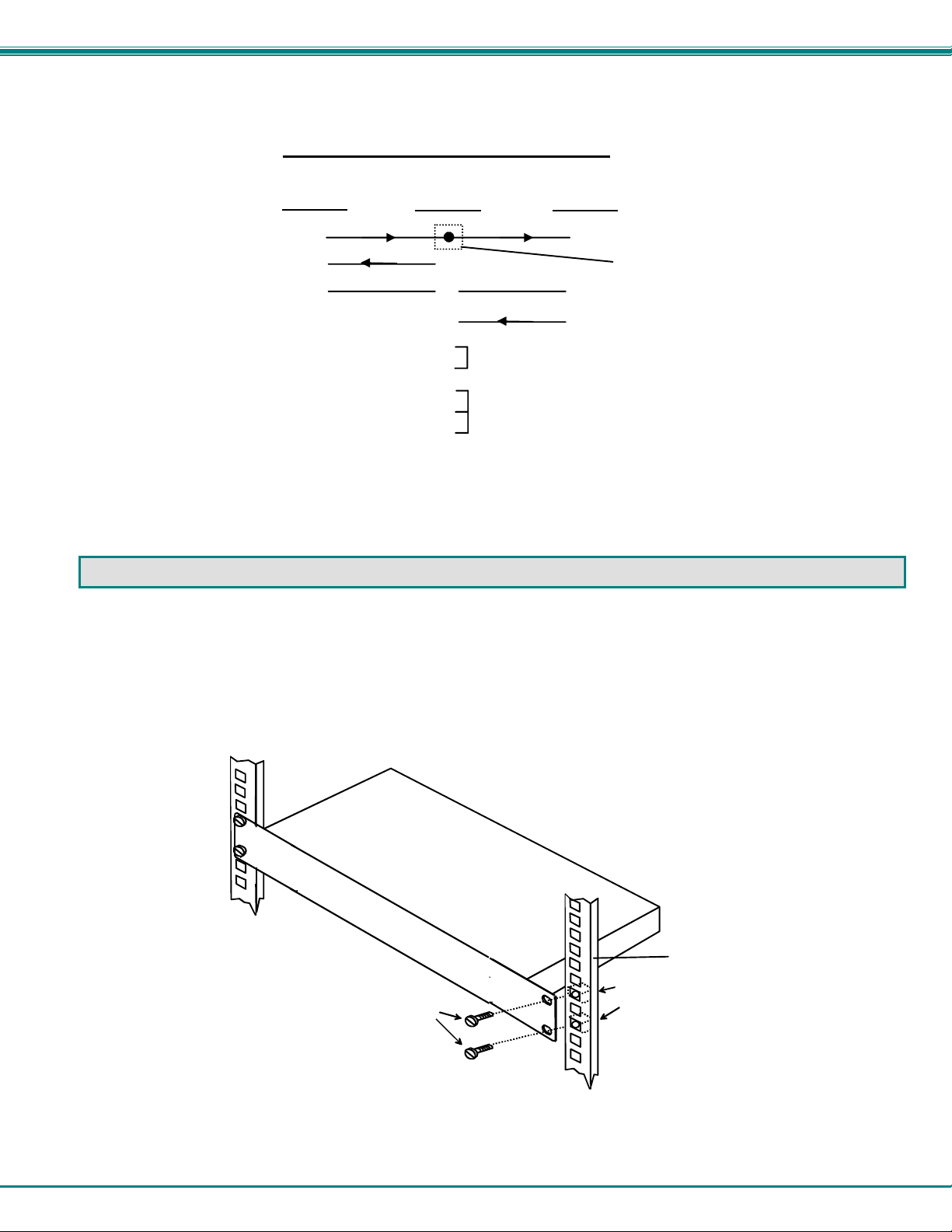
NTI VEEMUX VIDEO MATRIX SWITCH
Pinout for Matrix Y-1 Cable
Arrows indicate signal direction.
Wiring Schematic of Matrix-Y-1 cable
(Unit #1)
23
33
555
9D Female9D Male 9D Male
(Source)
(Unit #2)
Not connected to
source connector
22
7
Jumper
8
1
Jumpers
4
6
RACK MOUNTING INSTRUCTIONS
This NTI switch was designed to be directly mounted to a rack. It includes a mounting flange to make attachment easy.
Install 4 cage nuts (supplied) to the rack in locations that line up with the holes (or slots) in the mounting flange on the NTI switch.
Then secure the NTI switch to the rack using four #10-32 screws (supplied). Be sure to tighten all mounting screws securely.
Do not block power supply vents in the NTI switch chassis (if provided). Be sure to enable adequate airflow in front of and
behind the NTI switch.
Attach all cables securely to the switch and where necessary supply adequate means of strain relief for cables.
10-32
Rack Screws
(supplied)
Cage Nuts
(supplied)
Rack
36
Page 41
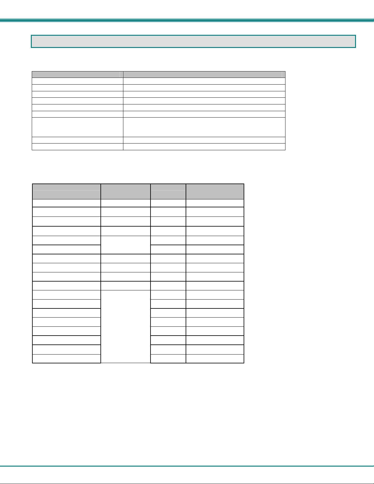
NTI VEEMUX VIDEO MATRIX SWITCH
SPECIFICATIONS
General Information
DESCRIPTION SPECIFICATION
Operating temperature -18°C - 55°C (0°F - 131°F) (17-90% non-condensing RH)
Storage temperature -30°C - 60°C (-20°F-140°F) (17-90% non-condensing RH)
Power requirements 110 or 220VAC @ 50 or 60Hz
Fuse protection 2A 240VAC Fast-blo
Video Connectors 15HD female
Maximum Resolution 1920 x 1200 @ 85Hz
Video Signal : Video
Bandwidth
Sync
Ethernet Connector RJ45 female, 10BaseT
RS232 Connector DB9 male, 300-9600 bps
Available Sizes
RGB analog (75 ohms, 0.7 Vp-p)
200MHz (typ) or greater
H/V separated (TTL), composite, sync-on-green
NTI Part # Desktop Size
(In.) WxDxH
SM-4X2-15V-LCD See below 1RU 19x10x1.75
SM-4X2-15V-LCD-DT 10x7.5x3.3
SM-8X2-15V-LCD 1RU 19x10x1.75
SM-8X2-15V-LCD-DT 10x7.5x3.3
SM-16X2-15V-LCD 1RU 19x10x1.75
SM-32X2-15V-LCD
SM-4X4-15V-LCD 1RU 19x10x1.75
SM-4X4-15V-LCD-DT 10x7.5x3.3
SM-8X4-15V-LCD 1RU 19x10x1.75
SM-8X4-15V-LCD-DT 10x7.5x3.3
SM-16X4-15V-LCD 1RU 19x10x1.75
SM-32X4-15V-LCD 2RU 19x10x3.5
SM-8X8-15V-LCD 1RU 19x10x1.75
SM-16X8-15V-LCD 2RU 19x10x3.5
SM-32X8-15V-LCD 2RU 19x12x3.5
SM-16X12-15V-LCD 2RU 19x12x3.5
SM-16X16-15V-LCD 2RU 19x12x3.5
SM-32X16-15V-LCD
N/A
N/A
Rack Units Rack Size
(In.) WxDxH
2RU 19x10x3.5
3RU 19x12x5.25
37
Page 42
NTI VEEMUX VIDEO MATRIX SWITCH
TROUBLESHOOTING
Problem Solution
No Video - Check power – power ON, power cable connected
- Check video cabling – make sure cables are secured
- Check connections – make sure you’re connected to an active input
SAFETY STATEMENTS
Grounding
These products have protective earth ground terminals and are built with full attention to consumer safety. There must be an uninterruptible safety earth ground between the main power source and the product's power cord or supplied power cord set.
If ever the possibility exists for the grounding protection to have been reduced in any way, disconnect the power supply until the
grounding connection has been fully restored.
Servicing
NTI products are not intended to be serviced in the field and contain no user-serviceable parts. In the event repair is needed, all
servicing must be performed by factory trained and authorized service personnel. Only those items specifically identified in this
manual (if any) may be adjusted by the user of this product and adjusted only as instructed in this manual.
INDEX
address, 9
Autostatus, 10
bandwidth, 1
batteries, 31
baud rate, 8,9
cables, 2
change battery, 31
DDC, 32
desktop chassis, 1
Device Discovery Tool, 26
dwell time, 8
Ethernet connection, 5
firmware, 23, 33
front panel LCD, 7
fuses, 3
grounding, 38
infrared remote, 27
IP address, 17, 19
IRT, 27, 28
Java, 26
LAN, 5
LED Matrix, 6
Matrix Switcher's Control Program, 11
mounting in a rack, 36
password, 2
resolution, 1
RS232 Control, 5,8
Scan Mode-LCD, 8
Scanning Sequences, 21
Serial Address, 20
SERTEST, 11
servicing, 38
specifications, 37
Stored Configurations, 19
Telnet Interface, 13
Telnet Interface-Port 2005, 14
Telnet password, 13
Telnet- Port 2000 Protocol, 13
Telnet-Port 2005 Protocol, 14
terminal, 5
unit address, 9
username and password, 17
video sources, 4
web browsers, 1
Web Interface, 17
WARRANTY INFORMATION
The warranty period on this product (parts and labor) is two (2) years from the date of purchase. Please contact Network
Technologies Inc at (800) 742-8324 (800-RGB-TECH) or (330) 562-7070 or visit our website at http://www.networktechinc.com
for information regarding repairs and/or returns. A return authorization number is required for all repairs/returns.
Man067 Rev 5/14/07
38
 Loading...