

Network Technologies RACKMUX-V15-8UNV, RACKMUX-V17-4UNV, RACKMUX-V17-8UNV, RACKMUX-V15-4UNV User Manual
Page 1
NTI
NETWORK
R
TECHNOLOGIES
INCORPORATED
1275 Danner Dr
Aurora, OH 44202
www.networktechinc.com
Tel:330-562-7070
Fax:330-562-1999
RACKMUX ®Series
RACKMUX-V15-4UNV
RACKMUX-V15-8UNV
RACKMUX-V17-4UNV
RACKMUX-V17-8UNV
KVM Drawer with Universal KVM Switch
Installation and Operation Manual
MAN089 Rev Date 10/23/2007
Page 2

TRADEMARK
RACKMUX is a registered trademark of Network Technologies Inc in the U.S. and other countries.
COPYRIGHT
Copyright © 2007 by Network Technologies Inc. All rights reserved. No part of this publication may be reproduced, stored in a
retrieval system, or transmitted, in any form or by any means, electronic, mechanical, photocopying, recording, or otherwise,
without the prior written consent of Network Technologies Inc, 1275 Danner Drive, Aurora, Ohio 44202.
CHANGES
The material in this guide is for information only and is subject to change without notice. Network Technologies Inc reserves the
right to make changes in the product design without reservation and without notification to its users.
i
Page 3

TABLE OF CONTENTS
INTRODUCTION.............................................................................................................................................................1
Models Available.......................................................................................................................................................1
Types of CPUs Supported........................................................................................................................................1
Features....................................................................................................................................................................1
MATERIALS....................................................................................................................................................................2
FEATURES AND FUNCTIONS.......................................................................................................................................3
INSTALLATION...............................................................................................................................................................4
Rack Mounting Instructions .........................................................................................................................................4
Connect The Cables....................................................................................................................................................4
Power-Up Sequence....................................................................................................................................................6
USING THE RACKMUX..................................................................................................................................................7
Keyboard Control.........................................................................................................................................................7
OSD Control ................................................................................................................................................................7
Security Option .........................................................................................................................................................7
Enabling the Security Feature ..................................................................................................................................7
User Login Mode.......................................................................................................................................................8
Additional Modes Available With Security...................................................................................................................8
Administration Mode.................................................................................................................................................8
Switch Configuration.................................................................................................................................................9
Exit Switch Configuration Mode.............................................................................................................................9
Administrator Password..........................................................................................................................................10
User Name List.......................................................................................................................................................10
System Access List.................................................................................................................................................11
User Access Functions..............................................................................................................................................11
Command Mode.....................................................................................................................................................11
Broadcast Mode......................................................................................................................................................13
Scan Mode..............................................................................................................................................................13
Normal Mode ..........................................................................................................................................................13
Edit Mode................................................................................................................................................................13
Search Mode...........................................................................................................................................................14
Maintenance Mode.................................................................................................................................................15
Help Mode...............................................................................................................................................................16
RS232 CONTROL.........................................................................................................................................................16
RS232 Connections and Configuration.....................................................................................................................16
Remote Connection................................................................................................................................................16
Configuration .............................................................................................................................................................17
Baud Rate...............................................................................................................................................................17
Loop Back...............................................................................................................................................................17
Unit Address ...........................................................................................................................................................18
Exit Switch Configuration Mode..............................................................................................................................18
Command Protocol....................................................................................................................................................18
Display Functions..........................................................................................................................................................21
Standard Controls......................................................................................................................................................21
OSD Control Menu ....................................................................................................................................................21
OSD Main Menu .....................................................................................................................................................21
Brightness/Contrast Menu......................................................................................................................................22
Color Menu .............................................................................................................................................................22
Position Menu.........................................................................................................................................................22
Setup Menu.............................................................................................................................................................23
Keyboard Functions ......................................................................................................................................................24
RACKMUX-V15-x......................................................................................................................................................24
Function Key Operation..........................................................................................................................................24
Number Pad...............................................................................................................................................................25
Other Functions of the "Fn" Key................................................................................................................................26
Numeric Keypad Option.............................................................................................................................................27
KEYBOARD FEATURES..............................................................................................................................................28
Keyboard-To-Computer Translation..........................................................................................................................28
ii
Page 4

Translation Capabilities ..........................................................................................................................................28
Translation Tables ..................................................................................................................................................28
TROUBLESHOOTING..................................................................................................................................................29
DEFAULT PASSWORD RESET...................................................................................................................................29
Rackmux-KVM Drawer Standard Specifications...........................................................................................................30
General Specs...........................................................................................................................................................30
LCD – 15” ..................................................................................................................................................................30
LCD – 17” ..................................................................................................................................................................30
Display Controller: VGA (-15 & -17) ..........................................................................................................................30
OSD Control Board....................................................................................................................................................30
Keyboard....................................................................................................................................................................31
Touchpad...................................................................................................................................................................31
INDEX............................................................................................................................................................................31
WARRANTY INFORMATION........................................................................................................................................31
TABLE OF FIGURES
Figure 1- Mount RACKMUX to rack...................................................................................................................................................4
Figure 2- Connect a PS/2 CPU..........................................................................................................................................................5
Figure 3- Connect a legacy SUN CPU ...............................................................................................................................................5
Figure 4- Connect the power cord and AC adapter ...........................................................................................................................6
Figure 5- Administrator Login screen.................................................................................................................................................7
Figure 6- User Login screen ..............................................................................................................................................................8
Figure 7- Administration Mode menu.................................................................................................................................................8
Figure 8- Switch Configuration Mode screen.....................................................................................................................................9
Figure 9- Administrator password change .......................................................................................................................................10
Figure 10- User Name List screen...................................................................................................................................................10
Figure 11- Command Mode menus .................................................................................................................................................12
Figure 12- Edit Mode screen............................................................................................................................................................13
Figure 13- Search Mode screen ......................................................................................................................................................14
Figure 14- Maintenance Mode screen .............................................................................................................................................15
Figure 15- Switch Configuration Mode screen.................................................................................................................................17
Figure 16- Daisy chain configuration with Matrix-Y-1 cable.............................................................................................................17
Figure 17- Matrix-Y-1 wiring schematic............................................................................................................................................18
Figure 18- OSD Controls .................................................................................................................................................................21
Figure 19- US(English) Keyboard Layout ........................................................................................................................................24
Figure 20- Keyboard LED Indications..............................................................................................................................................24
Figure 21- Keys of the Number Pad ................................................................................................................................................25
Figure 22- Additional multi-function keys.........................................................................................................................................26
Figure 23- U.S. (English) keyboard with numeric keypad................................................................................................................27
Figure 24- U.K. (English keyboard with numeric keypad.................................................................................................................27
Figure 25- German keyboard with numeric keypad.........................................................................................................................27
Figure 26- Locating the password reset button ................................................................................................................................29
iii
Page 5
NTI RACKMUX KVM Drawer with NODEMUX Switch
INTRODUCTION
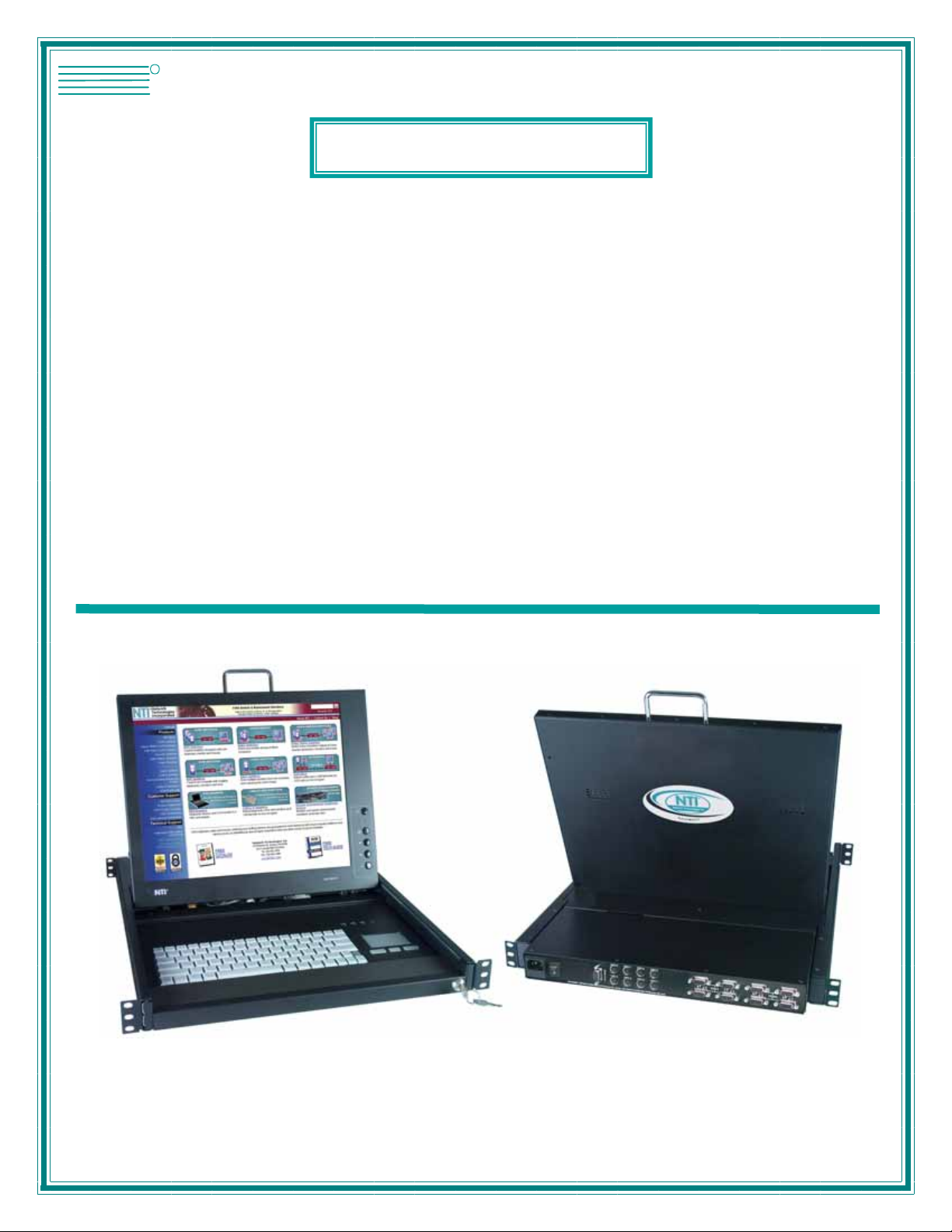
The RACKMUX-V15-8UNV (RACKMUX) is a KVM Drawer with Universal KVM Switch that combines a rackmount 15" TFT/ LCD
monitor, keyboard, touchpad mouse, an 8-port Universal KVM switch (NODEMUX) in a space-saving 1RU industrial strength
drawer with wrist pads. The RACKMUX is equipped with a built-in switch function, which all ows control of up to eight (8)
Windows or SUN-enabled CPUs with a single keyboard, touchpad and monitor. When access to a server rack is needed, the
drawer can be pulled out and the display lifted up like a notebook computer, revealing the keyboard and touchpad. When the
drawer is not in use, the display can be folded forward and down so the 1RU drawer can be pushed i nto the cabinet easily and
smoothly, helping to organize and streamline busy server rooms.
The onboard Universal KVM switch allows access to any Windows or SUN legacy CPUs from one monitor, keyboard and mouse
(up to 8 CPUs). These CPUs can be file servers, network managers, etc. Internal microprocessor circuitry allows all CPUs to be
booted simultaneously without keyboard error. Port selection is accomplished through On Screen Display (OSD) menus provided
for switch control and security administration.
Models Available
¾ RACKMUX-V15-4UNV - KVM Drawer with 15" TFT/LCD monitor and 4-port NODEMUX
¾ RACKMUX-V17-4UNV - KVM Drawer with 17" TFT/LCD monitor and 4-port NODEMUX
¾ RACKMUX-V15-8UNV - KVM Drawer with 15" TFT/LCD monitor and 8-port NODEMUX
¾ RACKMUX-V17-8UNV - KVM Drawer with 17" TFT/LCD monitor and 8-port NODEMUX
Types of CPUs Supported
• PS/2 (i.e. WINxx)
• Legacy SUN
• USB (when used with NTI USB-PS2 or USB-SUN Adapter)
Features
• Entire unit is only 1RU (1.75") high
• High-quality metal construction (ideal for most industrial and commercial settings)
• 15" or 17" Rack Mount LCD Monitor features a wide viewing angle
• 1024X768 resolution for 15" XGA monitor
• 1280x1024 resolution for 17" SXGA monitor
• A forward-folding 15” or 17” TFT LCD with built-in OSD menu for screen adjustments
• LCD Power-up when raised; manual override
• LCD Display controls (using on-screen menu)
• Includes rack mount kit suitable for SUN and most EIA 19" racks
• Fits varying rack depths from 22” to 39” deep via adjustable mounting brackets
• VGA/SVGA/XGA/SXGA Compatible
• Powered by 110-240VAC, 50 or 60Hz via IEC connector and country-specific line cord
• Auto shut-OFF switch: Turns OFF the power to the monitor when the LCD is in a folded-closed position
• Standard 3-button touchpad
• Added security with a drawer lock to prevent unwanted access
• Locking rails to prevent movement of the drawer when fully extended
• Keyboards available in multiple languages: English(US), English( UK), German, Italian, F r ench, and Spanish
Option:
• Numeric keypad option- for a separate 17-key numeric keypad, add “-N” to the part number (i.e. RACKMUX-V17-N-8UNV)
1
Page 6
NTI RACKMUX KVM Drawer with NODEMUX Switch
MATERIALS
Materials supplied with this kit:
• NTI RACKMUX-V15/17-4/8UNV KVM Drawer with Universal KVM Switch
• Line cord, country specific
• set of keys for keylock
• 2 Rear Mounting Brackets w/nuts
• 8 #10-32x3/4” screws and cage nuts for mounting to a rack
• CD with a pdf of this manual
Materials Not supplied but REQUIRED:
• A set of 2 cables for each CPU being connected to the switch:
• PS/2
CPU to Switch
- VEXT-xx-MM for video
- VKTINT-xx-MM for keyboard and mouse
• Legacy SUN
Switch
CPU to
OR
- VEXT-xx-MM for video
- 13W3M-15HDF (adapter for 13W3 to 15HD)
- SKTINT-xx-MM for keyboard/mouse interface
where:
xx is the length of the cable in feet
MM indicates male-to-male connector
Cables can be purchased from Network Technologies Inc by calling (800) 742-8324 (800-RGB-TECH) in the US and Canada or
(330) 562-7070 (worldwide).
interface
interface
interface
2
Page 7
NTI RACKMUX KVM Drawer with NODEMUX Switch
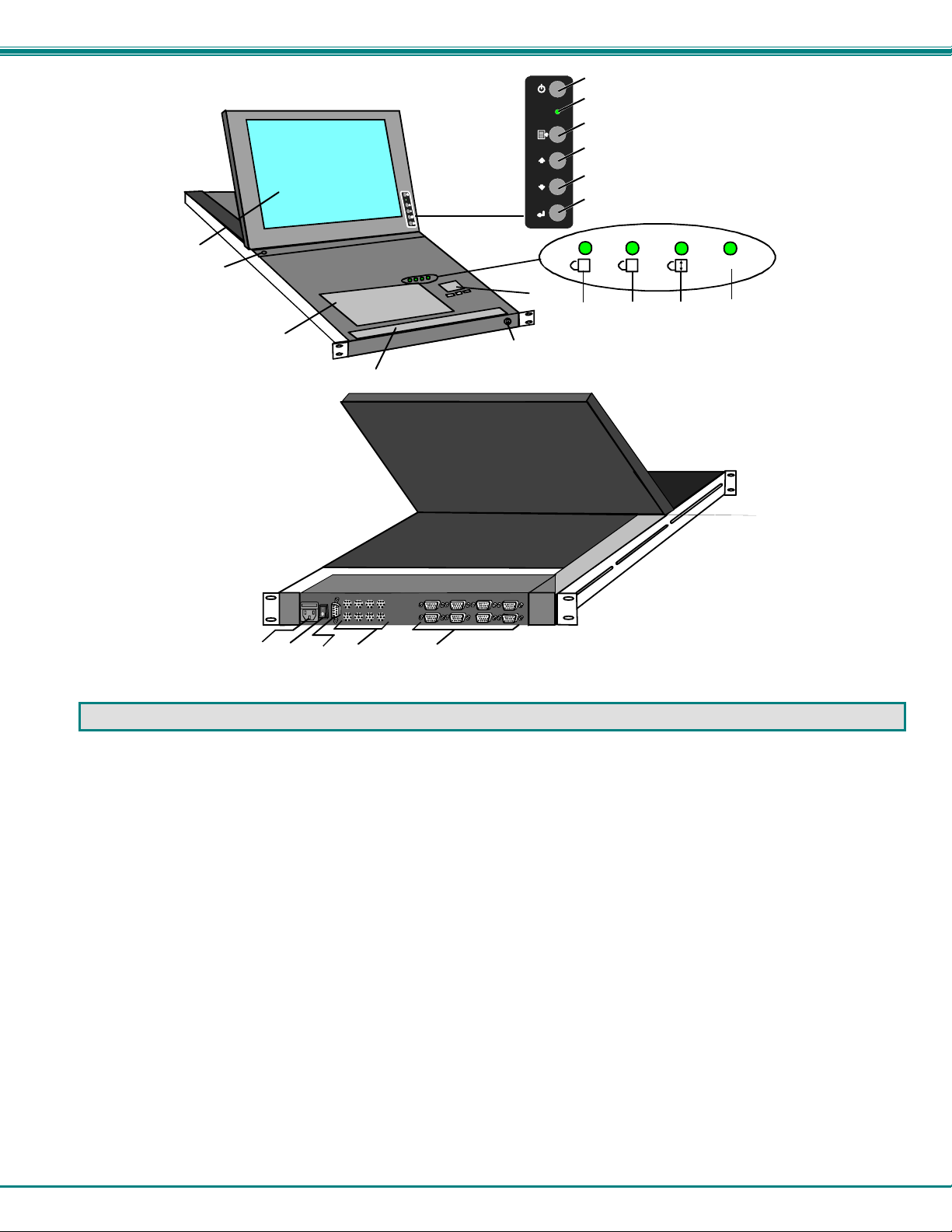
Front View
RACKMUX-V15-8UNV
11
12
17
15
19
20
16
13
14
2118
Rear View
RACKMUX-V15-8UNV
7
1
2
3
4
5
6
1
A
8
9
Fn
10
FEATURES AND FUNCTIONS
1. Power Button- press to turn the LCD monitor ON and OFF
2. Power LED- Indicates operation status
Green = Power-ON, Video Input Signal OK
Red = Suspend / Stand-by, or no Video Input Signal
3. Menu Button- press to turn ON the OSD menu
4. Up Arrow Button- press to move the cursor in the OSD menu up
5. Down Arrow Button- press to move the cursor in the OSD menu down
6. Select Button- press to select a menu item (when OSD menu is ON) or press to auto adjust the video quality (when OSD
menu is OFF)
7. NumLock LED- illuminates when the number lock is ON
8. CapsLock LED- illuminates when CapsLock is ON.
9. Scroll Lock LED- illuminates when the Scroll Lock keyboard feature is ON.
10. Fn LED- illuminates when Function Features (page 24) are enabled.
11. LCD Display- for viewing the video signal from the connected CPU
12. Auto Shut-OFF- switch automatically shuts OFF the LCD display when the monitor is folded down
13. 3-button touch pad- for controlling mouse movements on the monitor and controlling the computer
14. Keylock- to prevent unauthorized use of the RACKMUX
15. keyboard- for manual data entry and computer control
16. wrist rest- for user comfort
17. IEC Connector w/Built-in 2A 240VAC Replaceable Fuse- for attachment of the IEC power cord to power the RACKMUX
drawer
18. Switch- for powering ON and OFF the RACKMUX drawer
19. RS232- 9D female connector- for attaching RS232 interface cable from a remote terminal to control the functions of the
NODEMUX switch
20. CPU x- 8 pin miniDIN female connector-for connection of device cable from CPU(s)
21. VIDEO x- 15HD female connectors- for connecting video cables from CPUs
3
Page 8
NTI RACKMUX KVM Drawer with NODEMUX Switch
s
INSTALLATION
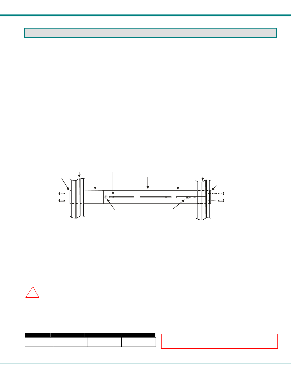
Rack Mounting Instructions
The RACKMUX was designed to be mounted to a rack and includes mounting flanges to make attachment easy.
1. Determine the mounting height in the rack for the drawer. It should be a height comfortable to use the keyboard and see the
LCD display. Mark holes in each of the 4 corner cabinet rails at points all level with each other.
2. Secure the rear brackets to the rear rack cabinet rails. Apply the top screws (not supplied) for each bracket to the holes
marked in step 1.
3. Lift the keyboard into position and line the studs on the left and right sides up with the slotted openings in the rear bracket.
Apply the nuts (supplied) to the studs but do not tighten the nuts yet.
FYI: There are 3 mounting studs provided on each side of the RACKMUX. Depending on the depth of the rack and
distance apart of the cabinet rails, the position of the rear bracket may make all 3 studs available for use. In this case,
apply the 2 nuts to the studs furthest apart from each other on each side.
4. Slide the drawer in until the top holes in the front bracket flanges line up with the holes marked in step 1. Secure the front
brackets on the drawer to the front cabinet rails with two screws per bracket. Be sure to tighten the screws securely. Then
tighten the nuts applied in step 3.
5. Apply one more screw to each of the rear brackets to finish.
Front brac ke t
flange on dra we r
Secure bracket
to rail using tw o
screws and nuts
(supplied)
Figure 1- Mount RACKMUX to rack
Front Cabine t
Rail
Drawer
Stud on dra wer
Rear bracket overlapping
drawer
Apply nuts (supplied) t o s tuds a nd
secure rear brackets to drawer.
(Rear edge
of dra w er)
Re ar Ca bi ne t
Rail
Rear bracket
flange
Secure bracket
to rail using two
screws and nut
(supplied)
Connect The Cables
1. Turn OFF power to all CPUs that will be connected to the NODEMUX before connecting or disconnecting any cables to or
from them.
WARNING! DAMAGE MAY OCCUR TO THE CPU IF POWER IS NOT DISCONNECTED BEFORE CONNECTING OR
!
DISCONNECTING CABLES.
2. Connect the appropriate NTI keyboard cable (see the chart below) from the input devices port (keyboard/mouse)
of a CPU to a CPUx port of the NODEMUX. Note the port’s number. (See Figs. 2 and 3.)
3. Connect a VEXT-xx-MM video cable and video adapter, if needed (see the chart below), from the video port of the same CPU
to the VIDEOx port of the NODEMUX with the same port number as the keyboard (see Figs. 2 and 3).
CPU Keyboard Cable Video Cable Video Adapter
PS/2 VKTINT-xx-MM VEXT-xx-MM None needed
SUN SKTINT-xx-MM VEXT-xx-MM 15DM-15HDF
4
NOTE: Make sure the CPU is connected to a CPU x
port and a VIDEO x port with the same number.
Page 9
NTI RACKMUX KVM Drawer with NODEMUX Switch
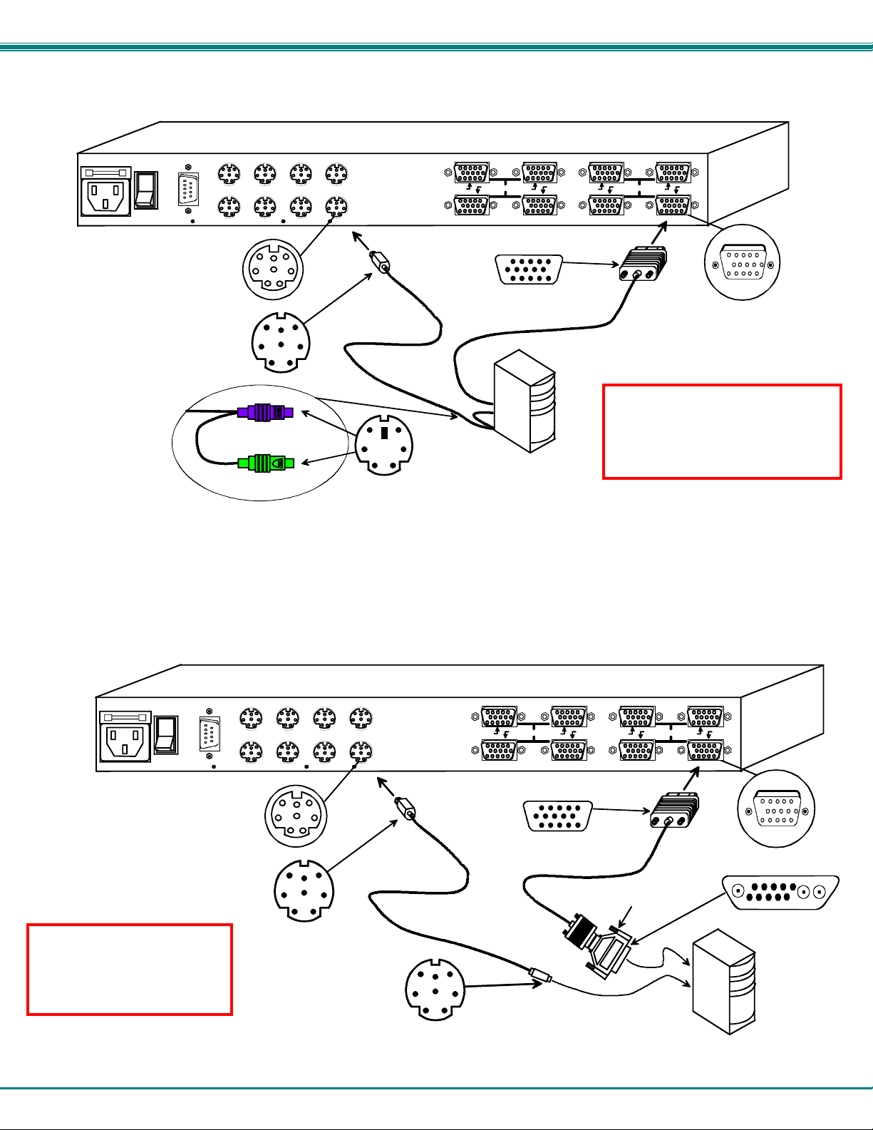
• PS/2 CPU- Connect a PS/2 CPU video port using a VEXT-xx-MM cable between a VIDEOx port on the NODEMUX and the
CPU. Connect the PS/2 CPU keyboard and mouse ports using a VKTINT-xx-MM cable between a CPUx port on the NODEMUX
and the CPU. (See Fig.2.)
CPU 8
CPU 7
CPU 4
NETWORK TECHNOLOGIES INC Tel:330-562-70701275 Danner Dr, Aurora, OH 44202 www. nti1.com
CPU 3
8 Pin miniDIN
Female
Connector
8 Pin miniDIN Male
Connector
(PURPLE-KEYBOARD)
(GREEN-MOUSE)
Figure 2- Connect a PS/2 CPU
• SUN CPU- Connect a SUN CPU video port using a VEXT-xx-MM cable with a 13W3M-15HDF adapter between a VIDEOx port
on the NODEMUX and the CPU. Connect the SUN CPU keyboard/mouse port using an SKTINT-xx-MM between a CPUx port
on the NODEMUX and the CPU. (See Fig. 3.)
NETWORK TECHNOLOGIES INC Tel:330-562-70701275 Danne r Dr, A u ro ra, O H 4420 2 www.nti1. com
CPU 8
CPU 4
CPU 7
CPU 3
8 Pin miniDIN
Female
Connector
Warning: Hardware is not
hot-pluggable to SUN CPUs.
SUN CPUs must be powered
OFF and unplugged before
connecting any cables.
8 Pin miniDIN Male
Connector
Figure 3- Connect a legacy SUN CPU
Rear View of NODEMUX in RACKMUX-V15-8UNV
CPU 6 CPU 5
CPU 2 CPU 1
VKTINT-xx-MM
8 4 7 3 6 2 5 1
15HD Male
Video Connector
VEXT-xx-MM
PS/2 CPU
6 Pin miniD IN
Male Connector
Rear View of NODEMUX in RACKMUX-V15-8UNV
CPU 6 CPU 5
CPU 2 CPU 1
SKTINT-xx-MM
8 Pin miniDIN M ale
Connector
8 4 7 3 6 2 5 1
15HD Male
Video Connector
VEXT-xx-MM
VIDEOVIDEO
15HD Female
Video Connector
Warning: Hardware is not hot pluggable at switch end of cable to
PS/2 CPUs. PS/2 CPUs must be
powered OFF before connecting
any cables to switch
VIDEOVIDEO
13W3M-15HDF
SUN CPU
15HD Female
Video Connector
Sun 13W3 Male
Video Connector
5
Page 10
NTI RACKMUX KVM Drawer with NODEMUX Switch
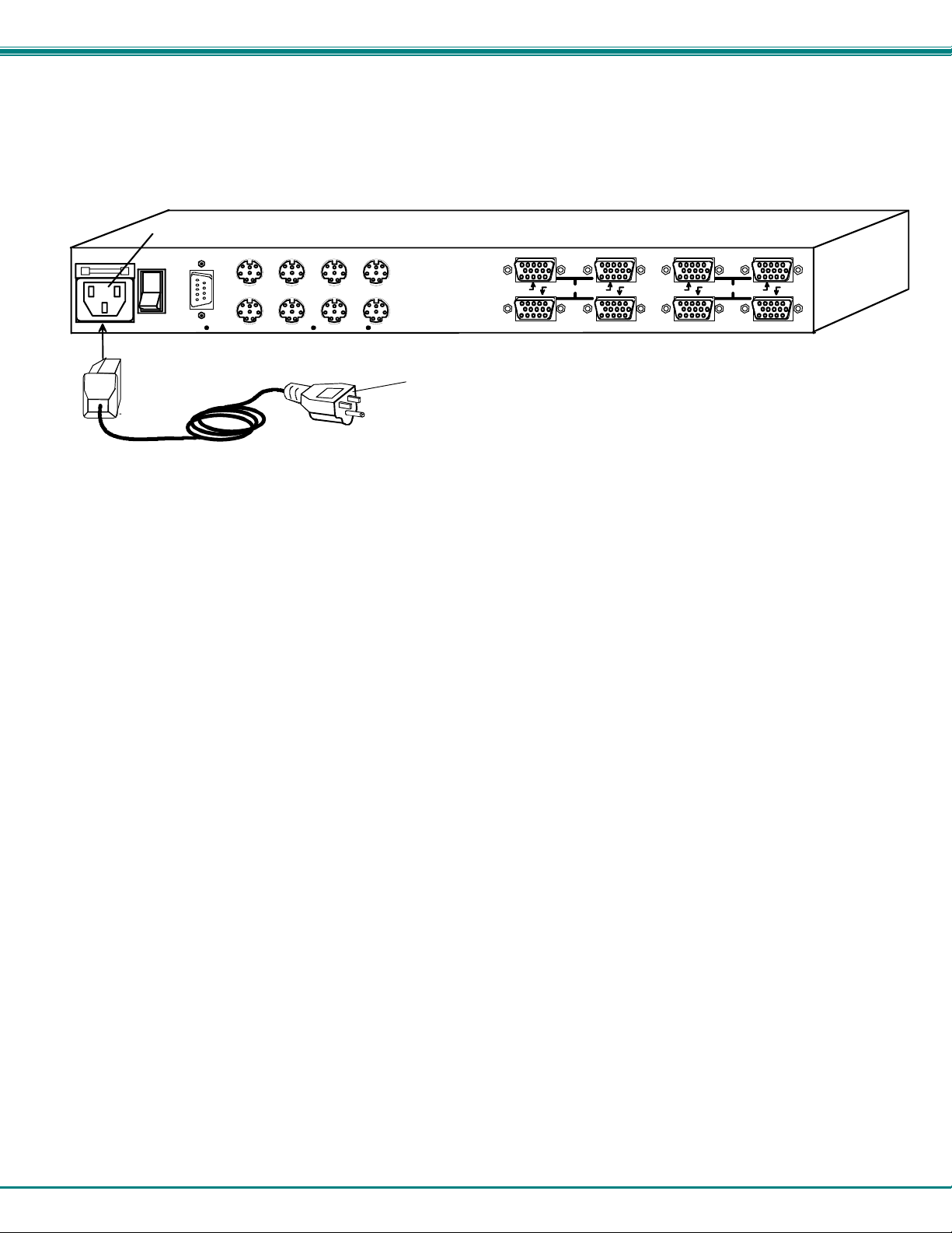
4. Connect the remaining input device and monitor interface cables from each CPU, making sure that cables from the each CPU
are connected to the NODEMUX switch at connectors with the same port numbers ("CPU 1" and "VIDEO 1 connectors,
"CPU 2" and "VIDEO 2" connectors...etc. )
5. Connect the power cord to the IEC connector.
NETWORK TECHNOLOGIES INC Tel:330-562-70701275 Danner Dr, Aurora, OH 44202 www.nti1.com
IEC Connectxor
CPU 8
CPU 4
CPU 7
CPU 3
Rear View of NODEMUX in RACKMUX-V15-8UNV
CPU 6 CPU 5
CPU 2 CPU 1
IEC Power Cord
Figure 4- Connect the power cord and AC adapter
8 4 7 3 6 2 5 1
VIDEOVIDEO
Power-Up Sequence
Note: It is very important that this power-up sequence be followed for all connected components to work properly.
1. Using the key, unlock the drawer and slide the keyboard and LCD Display out far enough to raise the display to a comfortable
viewing angle.
2. Power ON the NODEMUX with the power switch located at the rear of the RACKMUX.
3. Power ON the KVM Drawer with the power switch located at the rear of the keyboard.
4. Adjust the screen's brightness and contrast with the controls also located on the monitor– as needed.
5. Power ON any attached CPUs.
6
Page 11
NTI RACKMUX KVM Drawer with NODEMUX Switch
USING THE RACKMUX
Once the RACKMUX is properly connected, the NODEMUX will enable a connectio n to be made b etween the attached CPUs and
the monitor, keyboard, and mouse.
The NODEMUX can be controlled by three methods:
• keyboard control through Command Mode
• mouse clicks from within some menus of Command Mode
• RS232 control from a remote terminal
Keyboard Control
Keyboard control of the NODEMUX is achieved using Command Mode - operate d using the keyboard and mouse in
conjunction with OSD menus superimposed onto the monitor.
By pressing <Ctrl> + < ` > (accent key), the user can enter Command Mode. Once in Command Mode, typing a series of
commands will cause the NODEMUX to connect the user to any one CPU connected to the switch. Pressing the <Esc> key will
exit Command Mode. The following instruction describes how to use the menus to operate the NODEMUX Universal KVM switch.
OSD Control
OSD superimposes a menu system on the user’s video screen with a list of all connected CPUs. OSD allows CPUs to be named
(with up to 12-character names). OSD then allows selection of CPUs by that name. Connected CPUs can be listed by name or
by port number. OSD Search Mode enables the user to type in the first few characters of the CPU's name and the OSD will locate
it. Help screens assist with all OSD functions.
Security Option
The security option of the OSD Control enables an administrator to control access to CPU ports for each user. Up to 63 users
can be created. These users have controlled access to any selected CPU. Only the administrator can activate or deactivate the
security features. Security can be activated from the Maintenance Mode menu (page 15) with a successful administrator login for
verification purposes. Furthermore, the administrator can set a maximum idle time value after which the current user will be
logged out and the login screen displayed. This time out does not function while the OSD is active. The current security status,
idle time out, and scan dwell time are all saved and will be restored whenever power to the switch is cycled OFF, then ON.
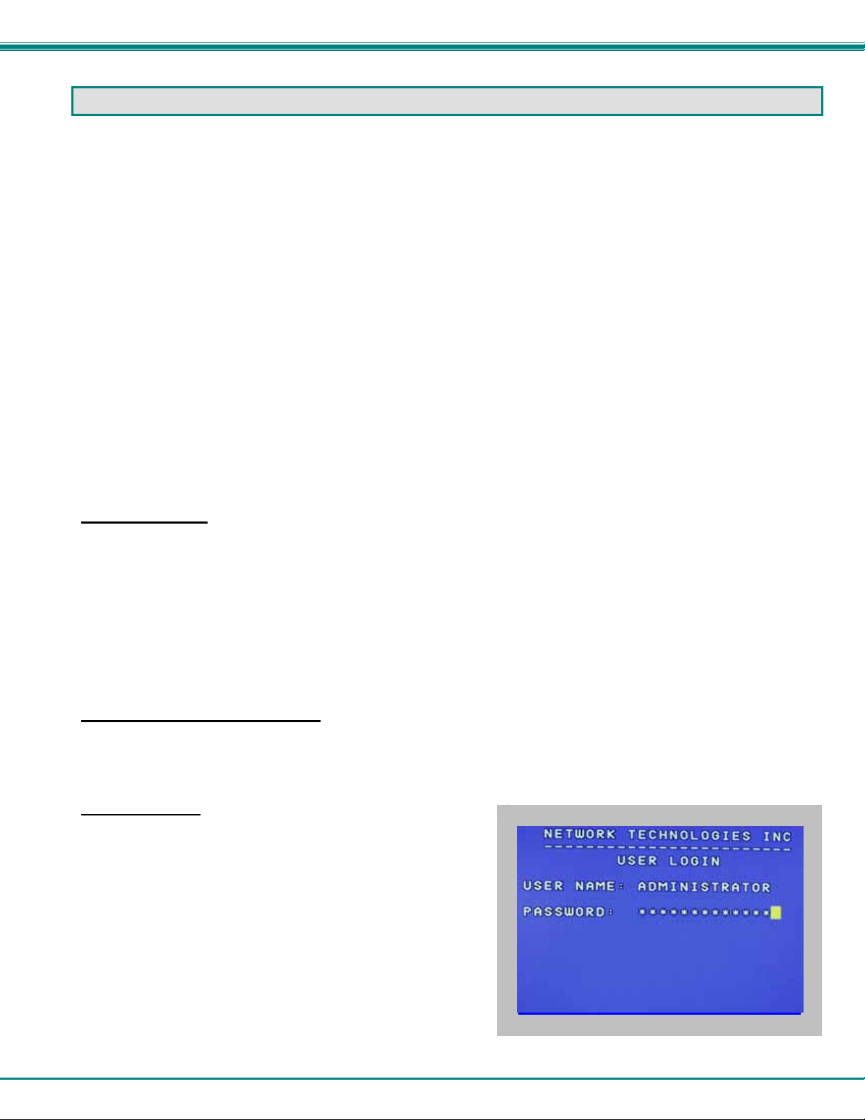
If the security option is enabled, when the RACKMUX is powered up the user will be prompted for a username an d password to
continue. If the security option is not enabled the monitor will display the desktop image for the connected CPU and the user can
continue with normal operation of the connected CPU.
Enabling the Security Feature
To enable the security feature the administrator must first enter Command Mode from the keyboard using the se quence
<Ctrl> + <`> (accent key). The OSD menu will automatically appear on the monitor. This provides a visual way to control the
NODEMUX using the keyboard and mouse.
The administrator
first time, may want to proceed directly to the ADMINISTRATION Mode
by typing <CTRL> +<M> , then <A>, and then <Y>.
The factory settings are:
, when setting the NODEMUX switch up for the
• default user name = ADMINISTRATOR
• default password = ADMINISTRATOR
Note: The user name for the administrator cannot be changed
from "ADMINISTRATOR".
Once logged-in, follow the instructions on page 10 for setting up users
and changing the password. Within the Administration Mode the
administrator can setup each of the users and the limitations of their
use of the individual CPUs attached to the switch.
Figure 5- Administrator Login screen
7
Page 12

NTI RACKMUX KVM Drawer with NODEMUX Switch
When a standard user powers up the system a security screen will appear if security has been enabled by the
administrator. The user will need to login to the switch by following the instructions below for the USER LOGIN. If the user
does not know the appropriate user name and password (setup by the administrator), contact the switch administrator for this
information. Once logged-in a user can follow the Command Mode functions described on page 9 to control the switch within the
limitations as determined by the administrator.
User Login Mode
User login mode requires a user to login with a user name and password from the list created by the administrator. This mode will
also disable use of the front panel until the user logs in.
Function: Keystroke:
Adds a character to the
user name/password
Removes previous character
from the user name/password
Submit user name/password
Exit USER LOGIN and return
to previous mode. This function
is only available if security is
not currently active.
If the password submitted is incorrect, the user will not
be able to proceed.
If the password submitted is correct, the user will
Figure 6- User Login screen
proceed to Normal Mode.
A-Z
(Type any alphabetical or numeric character)
0-9
Backspace
Enter
Esc
Additional Modes Available With Security
The three modes that follow are only available if the administrator is logged in.
Administration Mode
To enter the Administration Mode menu press <A> from the Maintenance Mode menu (page 15).
Administration Mode allows the administrator to use the following functions:
Function: Keystroke:
Configure switch- for application
and RS232 communication
Change the administrator’s
password
Disable security
Update User Name List
Figure 7- Administration Mode menu
W
C
S
U
8
Page 13

NTI RACKMUX KVM Drawer with NODEMUX Switch
Administration Mode (Cont'd)
Function: Keystroke:
Selects the idle time in minutes
Exit Administration Mode and
return to previous mode
T
Esc
(0-2)
-
x
(0-9)
-
x
-
(xxx from 000 to 255. i.e. T002
(0-9)
would set the time-out period
x
for 2 minutes. 000 will disable it)
Switch Configuration
Switch Configuration enables the administrator to configure the NODEMUX to be used as a stand alone switch or as one of the
switches in a cascaded system. Switch Configuration is also used to setup the communication settings for RS232
communication with a remotely connected terminal through the RS232 port.
Note: When used in a RACKMUX, the NODEMUX can only be used as a stand alone switch. Do not change this setting.
In the event the setting is changed from "stand alone" to "slave", when the switch is power cycled the OSD menu will
no longer work. To change it back to a "stand alone" switch, factory default settings must be restored via a terminal
connected to the RS232 control port. See RS232 Control on page 16 for how to restore default settings.
Do not change
this field.
Figure 8- Switch Configuration Mode screen
For more on configuring RS232 control, see "RS232 Control" on page 16.
Exit Switch Configuration Mode
Once changes are made to the Switch Configuration menu, press <Enter> and <Y> to save them.
To exit without saving
saving the changes made. .
Changes made will take effect the next time the NODEMUX is power cycled.
, press <Esc>, then <N>, then <Esc> again. The menu will return to the Administration Mode without
9
Page 14

NTI RACKMUX KVM Drawer with NODEMUX Switch
Administrator Password
To change the administrator password press <C> from the
Administration Mode menu.
The administrator is able to change the administrator
password as needed (see Fig. 9). Two edit fields are
available, one for password, the other for verify password.
The password can be up to 13 characters in length.
Note: The default password for the administrator is
ADMINISTRATOR.
Figure 9- Administrator password change
Function: Keystroke:
Add character to password string
or verify password string
Delete previous character in
edited string
Save new password.
Move to next field to be edited
Return to Administration Mode
A-Z
0-9
Backspace
Enter
Tab
Esc
or
Shift
(If Password string and Verify Password string
are different, this command will have no effect,
enabling the administrator to correct the password)
FYI: Once the password is setup, if the password
is lost of forgotten, see page 28 for instruction on
how to reset the password to the default
password.
+
A-Z
alphabetical or numeric character)
(Type any upper or lower case
User Name List
To enter the User Name List press <U> from the Administration Mode menu.
The User Name List displays the list of users and provides control for adding new users (up to 63), chang ing or assigning user
passwords, and changing access rights for any given user. User names may be up to 12 characters long, may not contain
spaces, and are not case sensitive. Passwords may be up to 15 characters long, may not contain spaces, and are case sensitiv e.
Function: Keystroke:
Edit the highlighted user’s
System Access rights
Enter Edit Mode to add/change/
remove users
Change the highlighted user’s
password
Exit the User Name List and
return to previous mode
Figure 10- User Name List screen
Esc
Ctrl
Ctrl
Ctrl
+
+
+
A
E
P
10
Page 15

NTI RACKMUX KVM Drawer with NODEMUX Switch
System Access List
The System Access List (accessible from the User Name List- page 10) displays a list of numbers representing the ports. From
this screen the administrator can change access rights to the ports for the selected user. The user’s name is displayed at the top
of the access list for reference. The mouse is used to change access rights by clicking on a given number to toggle a port’s
status. A user that has access to a port can connect to that port and control the CPU connected to that port when in Normal
Mode.
Function: Keystroke:
Save the changes to the access
list and return to previous mode
Exit the System access list without
saving and return to previous mode.
Enter
Esc
User Access Functions
Introduction
The OSD menu enables a user to name the CPUs connected to the NODEMUX switch and connect to them using that name.
The OSD is positioned on the monitor, displaying 8 CPU names at a time. The screen can be used for switching as well as editing
the CPUs’ names. Through the OSD menu, the user can operate the NODEMUX switch to have the switch cycle through 3
extended modes of operation: COMMAND, BROADCAST, and SCAN .
Command Mode
When entering the Command Mode from the keyboard using the <Ctrl> + <`> (accent key), the OSD menu will automatically
appear on the monitor. This provides a visual way to control the NODEMUX switch.
The list below describes the OSD Command functions available from the keyboard after entering Command Mode:
Function: Keystroke:
Select the previous port
Select the next port
Enable/disable Scan Mode
Enable/disable Broadcast Mode
Enter Edit Mode
Enter Maintenance Mode
Ctrl
Ctrl
Ctrl
Ctrl
+
+
+
+
S
B
E
M
Note: The user must be logged in as
administrator to access Edit Mode
11
Page 16

NTI RACKMUX KVM Drawer with NODEMUX Switch
Figure 11- Command Mode menus
Command Mode (Cont'd)
Function: Keystroke:
Sets scan time-out on
each port
Selects a specific port
Enters Search Mode and adds a character
to search string and selects the CPU’s
name that matches best.
Selects the first port on the switch
Selects the last port on the switch
Display Help Menu
Switch to a selected port
Exit OSD Command Mode
The mouse can also be used to control the NODEMUX switch within the Command Mode menu.
• The mouse cursor can be moved to the Scan, Help, Broadcast, Timeout, Maintenance and Exit fields where the user
can then click on the left mouse button to perform that function.
• Ports listed on the screen can be selected by moving the cursor onto that port and clicking. Clicking twice on a
selected port will switch to that port and exit Command Mode.
• To change the displayed ports on the screen simply click on the up and down arro ws located to the right of the port
names displayed.
Ctrl
Ctrl
A-Z
0-9
Home
End
F1
Esc
T
+
P
+
(Type any alphabetical or numeric character)
Enter
12
(0-2)
-
x
(0-9)
-
x
Press <CTRL> while in the Command Mode menu
to display the Edit, Maintenance, Port, and Timeout
control features.
Note: The user must exit Command Mode to
type to a CPU.
To exit Command Mode, either hold down any
touch-switch on the front panel for more than 2
seconds, OR press <ESC> on the keyboard.
(0-9)
-
-
x
-
(0-9)
x
(xxx from 002 to 255. ie. t002
(0-9)
would set the time-out period
x
for 2 seconds)
(Pxx would be P01, P02, etc.)
Page 17

NTI RACKMUX KVM Drawer with NODEMUX Switch
Broadcast Mode
To activate Broadcast Mode press <Ctrl> + <B> from the Command Mode menu.
(use with extreme caution or commands intended for one CPU will be sent to all CPUs)
Broadcast Mode allows the operator to send keystrokes to all active CPUs simultaneously (even those CPUs the user cannot
connect to due to lack of security access).
However, Broadcast Mode has some critical requirements:
• BROADCAST mode must be OFF when booting any attached CPUs.
• BROADCAST mode must be ON and COMMAND MODE must be OFF for keystrokes to reach attached CPUs.
NOTE: The user must type somewhat slowly when in Broadcast Mode (less than 20 wpm) and cannot use the
<Backspace> key.
Broadcast Mode is not supported by any ports that have MAC CPUs attached.
Scan Mode
To activate Scan Mode press <Ctrl> + <S> from the Command Mode menu.
When in Scan Mode the switch scans to each port with a CPU powered-ON. The port with the CPU powered-ON remains active
while in use. When the switch becomes idle for the configured time-out period (default time-out period is 5 seconds) the switch will
connect to the next powered-ON CPU port. See Command Mode section (page 11) for configuring the scan time-out period for
each port.
Note: The keyboard and mouse must remain idle for the full scan dwell time before the switch selects the next active
port.
Note: The scan dwell time set by the user only effects that user and has no effect on other switch users.
Normal Mode
When the NODEMUX switch is not in Command, Broadcast, or Scan mode, the user is in Normal Mode, controlling the CPU to
which the user is connected through the NODEMUX switch.
Edit Mode
To activate Edit Mode press <Ctrl> + <E> from the Command Mode menu.
Edit Mode enables the user to modify the names of the CPUs connected to the switch. Names of CPUs can be up to 12
characters in length. When in Edit Mode, multiple keystroke combinations are not valid (<Shift>+P, <Ctrl>+P, <Alt>+ P, and P will
all type a “P” to the display - lower case letters cannot be typed).
Function: Keystroke:
Move cursor one position
to the right
Move cursor one position
to the left
Move cursor to the
previous port
Move cursor to the
next port
Selects the first port on
the switch
Home
Figure 12- Edit Mode screen
13
Page 18

NTI RACKMUX KVM Drawer with NODEMUX Switch
Edit Mode (Con'td)
Function: Keystroke:
Selects the last port on
the switch
End
Toggles between insert
and overstrike
(The character either gets inserted and the remainder of the name
Insert
gets shifted to the right, OR the current character gets overwritten.)
Erase current character
Delete
Erase previous character
Backspace
When finished making changes in Edit Mode, press <Enter> and a prompt will appear to press either <Y> to save the changes or
<N> to continue making changes without saving the changes just made. If the <Esc> key is pressed instead of <Enter>, all
changes made will be ignored and the display will return to the prev ious menu.
Search Mode
To enter Search Mode, type any alphabetical or numeric character when the Command Mode menu is on the monitor.
Search Mode enables the user to enter and maneuver through a list of CPU names. The CPU name bes t matching the characters
typed is selected. The list of CPUs may also be searched for a specific (or similar) name. The following commands are valid when
the search option has been invoked from Command Mode.
Function: Keystroke:
Erase previous character
in search name
Move cursor one position to
the right in search name
Move cursor one position to
the left in search name
Select previous port
Select next port
Figure 13- Search Mode screen
Add a character to the search
string and select the best
matching CPU name
Exit Search Mode, return to
Command Mode
Switch to selected port
Backspace
A-Z
(Type any alphabetical or numeric character)
0-9
Esc
Enter
14
Page 19

NTI RACKMUX KVM Drawer with NODEMUX Switch
Maintenance Mode
To enter Maintenance Mode press <Ctrl>+<M> from the Command Mode menu.
Maintenance Mode enables a user to customize the On Screen Display to their requirements.
Function: Keystroke:
Reset all of the port names
Toggle between numeric and
alphabetic listing of ports
Move On Screen Display (OSD)
menu up on monitor
Move OSD menu down on
monitor
Move OSD menu to the right
Figure 14- Maintenance Mode screen
Move OSD menu to the left
Make OSD menu taller
Make OSD menu shorter
Change user password.
(Present only when a standard
user is logged in.)
Log current user out and return
to User Login Mode.
Activate security features
Present only when security is
available but not active.
Enter Administration Mode.
Option present only when Administrator
is logged in.
Save OSD window parameters
for the port
Return to Command Mode
.
R
L
T
S
P
Q
A
Esc
Note: If activating security features, the user will be
prompted for a “Y” (yes) or “N” (no) to confirm the
menu choice, at which point the user will be asked
for a username and password before continuing.
Only the administrator can activate the security
features.
Enter
15
Page 20

NTI RACKMUX KVM Drawer with NODEMUX Switch
Help Mode
To enter Help Mode press the <F1> key from the Command Mode menu (page 11).
Help Mode displays a list of commands with a short explanation of their function. These lists are organized in p ag es for each
mode (i.e. COMMAND, EDIT, and SEARCH). The following options enable the user to quickly obtain information on any
command
Function: Keystroke:
View the previous page of help
if available
View the next page of help
if available
Exit HELP and return to previous
mode
.
Page
Up
Page
Down
Esc
RS232 CONTROL
The NODEMUX can be configured to be controlled by a remote terminal connected through the RS232 port at the rear of the
NODEMUX. For RS232 communication with a remote terminal to work, the NODEMUX must first be configured for the baud rate
and address.
RS232 Connections and Configuration
Remote Connection
The RS232 Interface is designed to meet the RS232C standard and can be controlled from any CPU or other contro ller with an
RS232 communications port. The pin-out for the DB-9 connector on the unit is as follows:
RS232 Connector (DB-9 FEMALE)
PIN SIGNAL FUNCTION
1 CD Carrier Detect
2 TXD Transmit data (RXD at host)
3 RXD Receive data (TXD at host)
4 DTR Data terminal ready
5 GND Signal ground
6 DSR Data set ready
7 RTS Request to send
8 CTS Clear to send
9 - No connection
On the DB-9 female connector, pins 1 (DCD), 4 (DTR), and 6 (DSR) are shorted and pins 7 (RTS) and 8 (CTS) are shorted.
Therefore, host handshaking is bypassed and TXD and RXD are the only active signals. A straight through DB-9 cable (not null
modem) will work for most CPUs. To daisy chain multiple units, a Matrix Y-1 cable is used (see page 17) for each NODEMUX in
the chain.
Note: Security must be disabled or user access
granted on the port(s) to be selected by RS-232
control.
16
Page 21

NTI RACKMUX KVM Drawer with NODEMUX Switch
Configuration
Baud Rate
In order for a terminal to communicate with the NODEMUX, the terminal and NODEMUX must each be configured for the same
baud rate.
Press <W> from the Administration Mode menu (page 8) to enter Switch Configuration mode. (Fig. 15)
Press <Tab> once to move the cursor bar to highlight "RS232 BAUD RATE". The default setting is 9600.
Press <Up Arrow> or <Down Arrow> to change the selected baud rate to 300,600,1200,2400,4800, or back to 9600.
Do not change
this field.
Figure 15- Switch Configuration Mode screen
Note: When used in a RACKMUX, the NODEMUX can only be used as a stand alone switch. Do not change this setting.
In the event the setting is changed from "stand alone" to "slave", when the switch is power cycled the OSD menu will no
longer work. To restore the setting back to "stand alone", factory default settings must be restored via a terminal
connected to the RS232 control port. See the RS232 Command "CF" on page 19 to restore default settings.
Loop Back
In order for an RS232 command and a response to the command to be viewed at the terminal screen, the NODEMUX must have
its Loop Back feature enabled.
More than one NODEMUX may be connected to a terminal at a time. To do so, a Matrix-Y-1 cable (available from NT I) must be
used. (See Fig. 16). For each additional NODEMUX connected, another Matrix-Y-1 cable will be required.
If the NODEMUX is one of two or more switches being controlled via RS232, and if the NODEMUX is not that last switch in the
series of switches controlled, then this setting should be changed to "DISABLED".
If the NODEMUX is the only device controlled via RS232 , or if it is the last
this setting should remain "Enabled". (See Figure 16)
To enable or disable loopback, from the
Switch Configuration mode menu (above),
press <Tab> until the cursor bar
moves to highlight "LOOPBACK".
Press <Up Arrow> or <Down Arrow> to enable or
disable loopback as needed for the application.
Figure 16- Daisy chain configuration with Matrix-Y-1 cable
CPU
(terminal)
RS232
Serial Port
RS232
NODEMUX
SWITCH
First Unit
Disable Loopback Disable Loopback Enable Loopback
17
device in a series of devices being controlled, then
Matrix-Y-1
NODEMUX
SWITCH
Second Unit
Matrix-Y-1 Matrix-Y-1
RS232 RS232
NODEMUX
SWITCH
Last Unit
Page 22

NTI RACKMUX KVM Drawer with NODEMUX Switch
Figure 17- Matrix-Y-1 wiring schematic
Wiring Schematic of Matrix-Y-1 cable
9D Female9D Male 9D Male
(Unit #1)
23
33
555
(Source)
(Unit #2)
Not connected to
source connector
22
7
Jumper
8
1
Jumpers
4
6
Unit Address
In order for a terminal to communicate with one or more NODEMUX switches, each switch must have a unique address. The
NODEMUX will only respond to commands from a terminal if its address is embedded in the command. Up to 15 NODEMUX
switches can be connected in a "daisy chain" to a terminal, each with its own unique address.
To set the address of the NODEMUX, from the Switch Configuration mode menu (Fig. 15 on page 17),
press <Tab> until the cursor bar moves to highlight "RS232 UNIT ADDRESS".
press <Up Arrow> or <Down Arrow> until the desired address (1-15) is selected.
Exit Switch Configuration Mode
Once changes are made to the Switch Configuration menu, press <Enter> and <Y> to save them.
To exit without saving, press <Esc>, then <N>, then <Esc> again. The menu will return to the Administration Mode without
saving the changes made. .
Changes made will take effect the next time the NODEMUX is power cycled.
Command Protocol
Terminal control commands supported by the NODEMUX are defined below.
Notes:
• All commands should be terminated with an <Enter> (ASCII 13) denoted by <CR>. When a
command is sent, the entire string is echoed back to the terminal along with a response from the
addressed unit as shown in the command definitions. Unit response will be sent within 500 msec
after <CR>.
• All characters should be upper case, and all numbers below 10 should have a leading 0 (ex: 1 = 01).
• For units with one USER port (i.e. this NODEMUX switch), use 01 for the USER select.
18
Page 23

NTI RACKMUX KVM Drawer with NODEMUX Switch
RS - reset unit(s) to default power-up switch connections
FORMAT: RS AA<CR>
RS = "reset unit" command followed by at least one space
AA = unit address; if 00, all units on the bus will be reset and no response will be
returned
RESPONSE: *<CR> if command received and executed OK
-OR-
?<CR> if syntax or transmission error occurred
Note: The RS command does not change the switch configuration, it changes CPU-to-user connection settings.
CS - change single USER channel
FORMAT: CS AA,XX,YY<CR>
CS = "change single output" command followed by at least one space
AA = unit address
XX = input/CPU to connect
YY = output/USER to change
RESPONSE: *<CR> (command received and executed OK)
-OR-
?<CR> (syntax or transmission error occurred)
CA - change all output channels
FORMAT: CA AA,XX<CR>
CA = "change all outputs" command followed by at least one space
AA = unit address
XX = input /CPU to connect to all outputs/USERS
RESPONSE: *<CR> (command received and executed OK)
?<CR> (syntax or transmission error occurred)
FYI: In this NODEMUX switch, this command will have the same effect as the CS command above.
RO - read single USER channel
FORMAT: RO AA,YY<CR>
RO = "read output" command followed by at least one space
AA = unit address
YY = output/USER to read
RESPONSE: *<CR> (command received and executed OK)
XX<CR> (XX = input/CPU connected)
-OR-
?<CR> (syntax or transmission error occurred)
RU - read unit size
FORMAT: RU AA<CR>
RU = "read unit size" command followed by at least one space
AA = unit address
RESPONSE: *<CR> (command received and executed OK)
XX,YY<CR> (XX = # of CPU’s, YY = # of USERS)
-OR-
?<CR> (syntax or transmission error occurred)
19
Page 24

NTI RACKMUX KVM Drawer with NODEMUX Switch
RV- read unit software version
FORMAT: RV XX,00
RV= "read software version" command followed by at least one space
AA= unit address
00= command for the address location in memory of the software version
RESPONSE:
-OR-
?<CR> (syntax or transmission error occurred)
CF - reset all connected units, regardless of address, to factory default configuration settings
WARNING: THIS COMMAND WILL RESET ALL RS232 DAISY-CHAIN-CONNECTED NODEMUX SWITCHES TO
FACTORY DEFAULT SETTINGS. IF OTHER SWITCHES ARE DAISY CHAINED VIA RS232, DISCONNECT THEM BEFORE
SENDING THIS COMMAND.
FORMAT: CF 00
RESPONSE: (After 10-20 seconds)
COMMAND OK
RESET SWITCH CONFIGURATION IS COMPLETE
PLEASE RESET SWITCH POWER
FOR CHANGES TO TAKE EFFECT
20
Page 25

NTI RACKMUX KVM Drawer with NODEMUX Switch
DISPLAY FUNCTIONS
An NTI RACKMUX with a 17” monitor supports resolutions up to SXGA (1280 x 1024) with a refresh rate at between 55 and 76Hz.
When a 15” monitor is present, support for resolutions up to XGA (1024 x 768) apply with a refresh rate at between 55 and 76Hz.
The quality of the image on the LCD monitor is adjustable using an On Screen Display (OSD) menu using the control buttons on
the RACKMUX.
Standard Controls
The RACKMUX has 5 standard control buttons and a power LED. The 5 standard co ntrol buttons operate as follows:
• The Power button turns the RACKMUX LCD and backlight ON and OFF as desired.
• The Power LED located immediately below the Power button is a dual color
LED. It will illuminate with a green color when the RACKMUX is powered
ON and working properly. It will illuminate with a red color if the RACKMUX
is powered ON but there is no input signal detected.
• The Menu button is used to bring up the OSD menu where the various
settings of the LCD display can be adjusted. Once the OSD screen is
displayed, the Menu button is used to make selections within the menus.
See "OSD Control Menu" (below) for more on LCD display settings.
• The Up and Down Arrow buttons are used to navigate through the menus.
Move the cursor up or down as desired to highlight an item for selection.
Once an item is highlighted, pressing the Menu button will select it.
Figure 18- OSD Controls
• The Select button is used to make selections within the OSD menus when the OSD menu is ON. When the OSD menu is
OFF, the Select button will act as an Auto Adjust button to keep the user from having to use the menus to adjust the quality
of the image on the monitor.
Power
ON/OFF
Power LED
Menu
Up Arrow
Down Arrow
Select/
Auto Adjust
Controls for the
OSD Menus
OSD Control Menu
The OSD (On Screen Display) Menu enables the user to select the desired characteristics of the LCD di splay. To activate the
OSD Menu, press the Menu button (above). To turn the Menu back OFF, either select "EXIT" from the main menu or just wait
10-60 seconds and it will automatically be cleared from the screen.
OSD Main Menu
Selection Purpose Range
Brightness/Contrast Increase/decrease panel brightness/contrast level 1-100
Color R,G,B color temperature control 1-100
Position
Setup
Exit Exit from the OSD control menu
• Video Image horizontal and vertical position control
• Clock setting
• Phase control
• Control OSD Image position on screen
• Set time OSD will stay on screen before auto shutoff
• Select the language of the OSD menu
21
1-100
-10 to 60 seconds
Several languages (see page 8)
Page 26

NTI RACKMUX KVM Drawer with NODEMUX Switch
Brightness/Contrast Menu
Selecting the Brightness/Contrast menu will bring up a screen in which the user can adjust the brightness and contrast levels of
the LCD display. Using the Up or Down arrows to navigate the menu, highlight either the BRIGHTNESS or CONTRAST sections
and press the Select button to choose the option to adjust. Then use the Up or Down Arrow to adjust the setting.
Select EXIT when finished to return to the Main Menu.
Color Menu
Selecting the Color menu will bring up a screen in which the user can ad just the Red, Green, and Blue color levels (values from 1-
100) of the LCD display. With the RED, GREEN, or BLUE sections highlighted, (use the Up or Down arrow to move between
them), press the Select button to choose the option to adjust. Then use the Up or Down Arrow to adjust the setting.
Select EXIT when finished to return to the Main Menu.
Position Menu
Selecting the Position menu will bring up a screen in which the user can select AUTO ADJUST to automatically adjust the
horizontal and vertical position of the displayed image on the monitor, as well as adjust the clock and phase settings if they are not
correct. The user can also individually adjust these settings if so desired. With any of the sections highlighted, (use the Up or
Down arrow to move between them), press the Select button to choose the option to adjust. Then use the Up or Down Arrow
to adjust the setting as needed. Select EXIT when finished to return to the Main Menu.
22
Page 27

NTI RACKMUX KVM Drawer with NODEMUX Switch
Setup Menu
Selecting the Setup menu will bring up a screen in which the user can adjust
OSD POSITION-the position of the OSD menus on the LCD display
OSD TIME-the length of time the user can be idle before the OSD menu automatically exits (adjustable from 10
to 60 seconds)
LANGUAGE-the language that the OSD menus will be presented in
With the item highlighted, (use the Up or Down arrow to move between them), press the Select button to choose the option to
adjust. Then use the Up or Down Arrow to adjust the setting as needed. Select EXIT when finished to return to the Main
Menu.
OSD Image can be moved
to different points on the
display
23
Page 28

NTI RACKMUX KVM Drawer with NODEMUX Switch
KEYBOARD FUNCTIONS
RACKMUX-V15-x
The keyboard on the RACKMUX-V15-x (and RACKMUX–V17-x) is a standard condensed Windows format. To reduce the
keyboard size, some keys have been assigned multiple functions, accessible via the "Fn" key. This section will describe which
keys have multiple functions and how to enable them. Use the LEDs to know what special features are enabled.
Function Key Operation
The Function (“Fn”) key provides several special functions on the RACKMUX keyboard, includin g:
enabling otherwise standard keyboard keys to be used as the keys of a numeric keypad
enabling multi-function keys to change operation
To turn ON (lock) the Function key, press the “Fn” key twice quickly (double-click). The “Fn” LED will illuminate.
To turn OFF (unlock) the Function key, press the “Fn” key twice quickly again. The “Fn” LED will turn OFF.
Note: The "Fn" key will also operate similar to the shift key (with only momentary effect). Press and hold the "Fn" key
prior to pressing the special function key. The "Fn" key will remain active as long as it is depressed.
Esc
~
`
Tab
F2
F1
!
1
F3
@
#
2
3
WE R
Q
F6
F5
F4
%
$
5
4
F7
F8
F9
F10
&
^
7
6
789
T
YU I OP
(
*
9
8
CapsLock
Fn
Shift
ASDF GH JKL
123
ZXCVB
Ctrl
Alt
M
N
Alt
Function Key to enable additional key functions
Figure 19- US(English) Keyboard Layout
On= CapsLock
is locked
On= Function
Key feature
is ON
1
A
Fn
On= NumLock
is locked
On= Scroll Lock
is locked
Figure 20- Keyboard LED Indications
F11 F12
)
0
654
<
,
Num Lk
Insert Delete
Prt Sc
+
=
}
{
]
[
Enter
:
"
;
'
+
*
?
>
.
.
Shift
/
/0
Ctrl
Home
Sys Rq
Backspace
Pg Up
Enter
Pause
BreakScr Lk
\
EndPg Dn
24
Page 29

NTI RACKMUX KVM Drawer with NODEMUX Switch
Number Pad
The functionality of a Number Pad on a standard Windows keyboard has b een incorporated into the keyboard of the
RACKMUX-V15. To substitute the keys of the Number Pad
To substitute the keys of the Number Pad:
1. Press the "NumLock" key. The NumLock LED ( ) will illuminate.
2. Press the "Fn" key twice quickly (double-click). The "Fn" LED will illuminate.
To turn OFF Number Pad functions:
1. Press the "Fn" key twice quickly (double-click). The "Fn" LED will turn OFF.
2. Press the "NumLock" key. The NumLock LED ( ) will turn OFF.
With the Fn and NumLock LEDs illuminated, pressing some standard keys will result in displa ying characters as
indicated in the chart below.
Standard Key Displayed when NumLock is
ON
J
K
L
U
J
O
7
8
9
M
.
(period)
/
(forward slash)
;
(semicolon)
í
(apostrophe)
-
(hyphen)
[
(left bracket)
&
7
789
*
8
1
2
3
4
5
6
7
8
9
0
.
(period)
(
9
1
1
1
/
(forward slash)
+
(plus sign)
*
(asterisk)
-
(minus sign)
ENTER
Function when NumLock is
OFF
End
Down Arrow
Page Down
Left Arrow
---
Right Arrow
Home
Up Arrow
Page Up
Insert
Delete
Num Lk
Scr Lk
UIO
654
{
[
Enter
JKL
123
:
;
+
"
'
*
M
>
.
.
?
/
/0
Figure 21- Keys of the Number Pad
25
Page 30

NTI RACKMUX KVM Drawer with NODEMUX Switch
Other Functions of the "Fn" Key
The Function ("Fn") key will enable other standard keyboard features in addition to the N umber Pa d keys (page 25) .
Key Function when Fn key is
not locked ("Fn" LED is OFF)
Numlck (Number lock) Scr Lck (Scroll Lock)
Insert Prt Sc (Print Screen)
Delete Sys Rq (System Requirements)
Pause Break
Up Arrow Page Up
Down Arrow Page Down
Left Arrow Home
Right Arrow End
NUMLCK
SCR LCK
INSERT DELETE
PRT SC
SYS RQ
PAUSE
BREAK
Figure 22- Additional multi-function keys
Note: The "Fn" key will also operate similar to the shift key (with only momentary effect).
Key Function when Fn key is
Locked ("Fn" LED is ON)
PG UP
HOME
ENDPG DN
26
Page 31

NTI RACKMUX KVM Drawer with NODEMUX Switch
Numeric Keypad Option
Models with the Numeric Keypad option (-N) (i.e. RACKMUX-V15-N-8UNV) have a standard Windows keyboard with 17-key
numeric keypad.
Note: The “Fn” key is not an active key on this keyboard.
Esc
Tab
~
`
F2
F1
!
1
Q
F3
F4
@
#
2
$
3
4
WE R
F6
F5
%
5
F7
F8
F9
F10
&
^
7
6
T
YU I OP
(
*
9
8
F11 F12
)
0
Caps Lock
ASDFGH JKL
:
;
Shift
ZXCVB
N
<
>
,
M
.
Fn
Ctrl
Alt
Alt
Figure 23- U.S. (English) keyboard with numeric keypad
Esc
F2
F1
F3
F4
F6
F5
F7
F8
F9
F10
F11 F12
`
"
!
2
1
3
%
$
5
4
&
^
7
6
*
8
)
(
0
9
Tab
WE R
Q
T
YU I OP
Caps Lock
ASDFGH JK L
:
;
Shift
ZXCVB
N
<
>
,
M
.
Ctrl
Fn
Alt
\
AltGr
Figure 24- U.K. (English keyboard with numeric keypad
Esc
F2
F1
F3
F4
F5 F6 F7
F8
F9 F10
F11 F12
^
"
!
1
2
2
3
3
%
$
4
&
6
5
/
7 {
(
8 [
)
9 ]
=
0 }
?
\
Tab
Q
WE R
@
T
ZU I OP
ASDF GH JK L
O
YXCVB
N
;
:
,
M
u
.
Strg
Fn
>
Alt
<
AltGr
Figure 25- German keyboard with numeric keypad
PrtSc
SysRq
PrtSc
SysRq
{
[
?
/
Insert
Druck
S-Abf
U
Einfg
{
[
?
/
Insert
A
Scroll
Pause
Delete
Break
Lock
+
Backspace
=
}
]
"
Enter
'
Shift
Scroll
Lock
+
Backspace
=
}
]
@
Enter
'
Shift
Rollen
*
+ ~
Pause
Break
Pause
Untbr
Home
Page
\
Up
Page
Down
End
Delete
Home
~
Page
#
Up
Page
Down
End
Entf
Pos1
Bild
'
#
Bild
Ende
Num
Lock
/
789
Home Pg Up
456
123
End
0
Ins
Num
Lock
/
789
Home
456
123
End
0
Ins
Num
/
789
Pos1
456
123
Ende
0
Bild
Bild
PgDn
PgUp
PgDn
Del
*
.
Entf Einfg
Del
*
.
-
*
+
Enter
.
-
+
Enter
-
+
Enter
27
Page 32

NTI RACKMUX KVM Drawer with NODEMUX Switch
KEYBOARD FEATURES
The keyboard configuration of each CPU is saved in the NODEMUX s witch. For examp le, if the CPU a ttached to Port 2 had
CAPS LOCK and NUM LOCK selected the last time that CPU was accessed, then they will automatically be set when that CPU is
accessed again.
Keyboard-To-Computer Translation
The NODEMUX switch enables a mixture of other wise incompatib le peripheral computer components to be connected together.
This is accomplished by performing keyboard-to-computer translations automatically (i.e. translate the Windows keyboard and
mouse to a SUN type CPU). The chart below shows the capabilities of the keyboard controlling certain CPU types.
Translation Capabilities
CPU
Device Sun Mac Windows
RACKMUX Keyboard Extra keys emulation Power key emulation Full functionality
Translation Tables
Use the charts below to type SUN’s additional keys with the RACKMUX keyboard:
SUN Extra Keys
RACKMUX keyboard Sun Extra Keys
Space Bar + F1 Stop
Space Bar + F2 Again
Space Bar + F3 Props
Space Bar + F4 Undo
Space Bar + F5 Front
Space Bar + F6 Copy
Space Bar + F7 Open
Space Bar + F8 Paste
Space Bar + F9 Find
Space Bar + F10 Cut
Space Bar + F11 Help
Space Bar + F12 Compose
Space Bar + Up Arrow Volume +
Space Bar + Down Arrow Volume Space Bar + Left Arrow Mute
Power Key Emulation
RACKMUX Keyboard Mac CPU Sun CPU
Space Bar + RT Arrow Power Power
28
Page 33

NTI RACKMUX KVM Drawer with NODEMUX Switch
TROUBLESHOOTING
PROBLEM:
SOLUTION:
PROBLEM:
SOLUTION:
Keyboard Errors
Check cable connections on each CPU and the switch.
No Video
Check cable connections on each CPU and the switch. Verify that keyboard and video connect from each CPU
to matching ports. After reconnecting, CPU may need to be re-booted in order to sense the monitor connection.
PROBLEM:
SOLUTION:
No OSD
The administrator may have configured the unit as a slave instead of stand-alone switch. OSD will not work
when a NODEMUX is configured as a slave. To reconfigure the switch to a stand-alone configuration, see
RS232 Control , "CF" command on page 20.
BE SURE TO READ WARNING BEFORE USING THIS COMMAND.
PROBLEM:
SOLUTION:
No Keyboard or Mouse
Shut down CPU's. Power cycle the switch. Turn on CPU's.
DEFAULT PASSWORD RESET
In the event the Administrator password is lost or forgotten, the password can be reset to the default password of
ADMINISTRATOR. Figure 26 shows the location of the password reset button.
Rear View
RACKMUX-V15-8UNV
Figure 26- Locating the password reset button
To reset the password;
1. Turn the power OFF to the NODEMUX.
2. Press and hold the password reset button. (Stick something non-conductive into the small openi ng to depress the
button inside.)
3. Turn the power ON to the NODEMUX.
For instruction on how to change the default administrator password, see page 10.
4. Release the password reset button.
Password Reset Button- Press to reset administrator password to default "ADMINISTRATOR"
Front View of NODEMUX insid e RACK MUX - V15 -8 UNV
R
NTI
Network Technolog ies Inc
TM
29
Page 34

NTI RACKMUX KVM Drawer with NODEMUX Switch
RACKMUX-KVM DRAWER STANDARD SPECIFICATIONS
General Specs
Case Material.................................................Electro-galvanized steel black powdercoated
Dimensions WxDxH (in.)...............................19 x 21.9 x 1.75
Supported Rack Depths………………………..Adjustable 22” – 39”
Input Power....................................................AC 100-240V, 50 – 60 Hz
Operating Temperature..................................0-40˚C
Storage Temperature…………………………..-20-60˚C
Relative Humidity……………………………….. 20-90%, non-condensing
Approvals.......................................................All parts comply with RoHS
LCD – 15”
Display area…………………………………….304.1mm (W) x 228.1 (H) (15 inch diagonal)
Panel Type………………………………………TFT Active
Number of Pixels ...........................................1024 (H) x 768 (V)
Number of Colors...........................................16.2 Million
Pixel Pitch......................................................0.297(H) x 0.297(V)
Color Pixel Arrangement.................................RGB Vertical Stripe
Brightness......................................................250cd/m^2 (Nits)
Response Time..............................................16ms
Viewing Angle................................................Horizontal: 140º; Vertical: 125º (Typ.)
Optimum Viewing Direction............................6 o’clock
Backlight Unit……………………………………2x CCFLs (Top & Bottom, edge-light)
Operating Lamp Life ......................................30,000 – 40,000 hrs
Contrast Ratio…………………………………..500:1
LCD – 17”
Display area…………………………………….337.92mm (W) x 270.336 (H) (17 inch diagonal)
Panel Type………………………………………TFT Active
Number of Pixels ...........................................1280 (H) x 1024 (V)
Number of Colors...........................................16.2 Million (6 bits + FRC)
Pixel Pitch......................................................0.264(H) x 0.264(V)
Color Pixel Arrangement.................................RGB Vertical Stripe
Brightness......................................................300cd/m^2 (Nits)
Response Time..............................................5.5ms
Viewing Angle................................................Horizontal: 140º; Vertical: 130º (Typ.)
Optimum Viewing Direction............................6 o’clock
Backlight Unit……………………………………CCFL, 4 Tables, Edge-Light (2 Top/2 Bottom)
Operating Lamp Life ......................................40,000 – 50,000 hrs
Contrast Ratio…………………………………..500:1
Display Controller: VGA (-15 & -17)
Connector………………………………………15HD, female
Video Format.................................................VGA,SVGA, XGA, SXGA (17” only)
Signal Input (from Video Source)…………….Analog RGB
Sync Range...................................................H: 31 ~ 80KHz, V: 55 ~ 76Hz
OSD Control…………………………………….Menu, Up, Down, Select, Power (5 keys)
Plug and Play.................................................VESA DDC 2B Ver1.3
OSD Control Board
OSD Control ..................................................5 Keys
Power Key .....................................................Power ON/OFF
Menu Key.......................................................Activates Menu
Up, Down Keys..............................................Navigation Control
Select Key......................................................Select (when in Menu); Auto Adjust (not in menu)
LED................................................................Indicates Operation Status
...............................................................Green = Power-ON, Video Input OK
...............................................................Red = Suspend / Stand-by, or Input Out of Range
30
Page 35

NTI RACKMUX KVM Drawer with NODEMUX Switch
Keyboard
No. Of Keys ...................................................83 Keys (US), 84 keys (German, French, Italian, Spanish)
Key Switch Type............................................Membrane switch
Keytop Style...................................................Rectangular Cylindrical
Operating Force.............................................50gf +/- 25gf
Stroke ............................................................3.0mm +/- .5mm
Tactile............................................................20 gf typ.
Height ............................................................8.5 mm
Operating Life................................................10M operations, minimum
Interface ........................................................ Row and column matrix
Key Switch Bounce........................................10 ms, maximum
Touchpad
Motion Detection Method...............................capacitance sensing
X/Y Position Sensing Resolution ...................40 counts/mm
X/Y Position Reporting...................................Relative (Similar to mouse)
Tracking Speed..............................................Up to 1016 mm/sec
Touch Force...................................................No Contact pressure required
Lifetime (Plastic Overlay)...............................Minimum 10,000,000 strokes
Sample Rate..................................................Up to 100 samples/sec
INDEX
A
dministration Mode, 8
Administrator password change, 10
Broadcast Mode, 13
Command Mode, 11
configure baud rate, 17
connect cables, 4
Default password reset, 29
Display functions, 21
Edit Mode, 13
Fn key, 24
Function key, 24
Keyboard Control, 7
Keyboard LEDs, 24
keyboard translation, 28
LEDs, 24
loop back, 17
Maintenance Mode, 15
materials list, 2
Number Pad, 25
numeric keypad, 27
OSD Control, 7
OSD Controls, 21
passwords, 7
Power-up Sequence, 6
rack installation, 4
RS232 Control, 16
Scan Mode, 13
Search Mode, 14
Security, 7
Specifications, 30
Switch configuration, 9
System Access list, 11
User access, 11
User Name list, 10
WARRANTY INFORMATION
The warranty period on this product (parts and labor) is two (2) years from the date of purchase. Please contact Network
Technologies Inc at
for information regarding repairs and/or returns. A return authorization number is required for all repairs/returns.
(800) 742-8324 (800-RGB-TECH) or (330) 562-7070 or visit our website at http://www.networktechinc.com
MAN089 Rev 10/23/07
31
 Loading...