

Page 1
ST-C5MK-VESA
VESA MOUNTING BRACKET KIT
Installation Instruction
The ST-C5MK-VESA is a VESA Mounting Bracket Kit that allows an NTI extender (XTENDEX) to be easily mounted to the back of a
flat panel monitor enabling simple and clean cable routing and saving valua ble desk space. The ST-C5MK-VESA is provided with
two sets of mounting holes compliant to VESA 75mm and 100mm mounting hole patterns. Two sets of standoffs allow the NTI
XTENDEX to be attached such that cables can approach from any of 4 directions. See the chart below for XTENDEX models that
can be mounted using the ST-C5MK-VESA.
Compatible XTENDEX Models Where to find:
http://www.networktechinc.com/cat5.html
ST-C5x-600: Remote Units only
ST-C5x-300: Remote and Local Units
http://www.networktechinc.com/cat5-vga.html
http://www.networktechinc.com/cat5-300.html
http://www.networktechinc.com/cat5-300-vga.html
http://www.networktechinc.com/cat5-1000.html
ST-C5x-1000: Remote Units only
http://www.networktechinc.com/cat5-1000-vga.html
Installation
1. If the existing monitor support arm bracket (see picture on page 3 for reference) has not already been removed from the monitor,
remove it now.
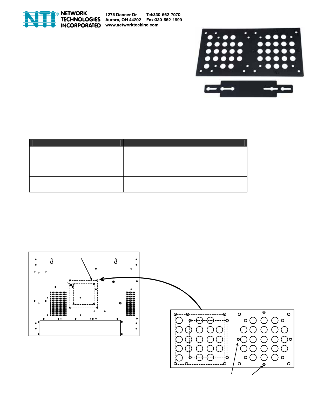
2. Place the large ST-C5MK-VESA mounting bracket between the support arm bracket and the monitor. The holes in the support
arm bracket will line up with either the holes in the VESA 75mm pattern or the 100mm pattern (see image below). Reapply the screws
to secure the support arm bracket and the large ST-C5MK-VESA mounting bracket to the monitor. Be sure to tighten the screws
securely.
Hole pattern for
75mm mounting
Hole pattern for 100mm mounting
Place VESA mounting bracket between the monitor mou nti ng
plate and the monit or. Use either the 75mm hole pattern or
the 100mm hole pattern.
Rear View of LCD monitor
Standoffs for mounting the XTENDEX
1
Page 2
Place bracket on XTENDEX ove r scre ws
and slide into keyhole slot. Tighten
screws on back of XTENDEX
3. Loosen the two screws on the back of the XTENDEX and apply the small
Loosen screws on back
of XTENDEX
mounting bracket supplied with your kit. Slide the bracket so that the screws
on the XTENDEX are captured in the slots in the bracket. Tighten the screws.
Note: Some models of NTI XTENDEX instead have extra holes on the back
for mounting this bracket and require two additional screws to be applied.
Two extra #4-40 x 3/16” screws have been supplied with this kit for this
purpose.
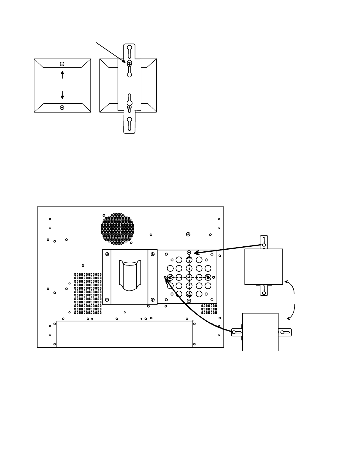
4. Determine the desired mounting position for the XTENDEX on the monitor such that the cables will best approach the XTENDEX for
easy cable routing.
5. Loosely apply the two screws provided to the standoffs on the VESA mounting bracket that will be used to hol d the XTENDEX in the
desired position (see image below).
6. Apply the XTENDEX to the two screws through the openings in the keyhole slots, slide the XTENDEX to capture the small mounting
bracket under the screw heads, and tighten the screws.
Secure XTENDEX t o the VES A m ount ing
bracket using 2 screws supplied.
(Two sets of standoffs are provided for
your choice of mounting positio n. )
XTENDEX
-OR-
XTENDEX
7. Hardware installation is complete. (See image on page 3.) Attach cables.
2
Page 3

ST-C5MK-VESA
Existing support arm bracket
Warranty Information
The warranty period on this product (parts and labor) is two (2) years from the date of purchase. Please contact Network
Technologies Inc at (800) 742-8324 (800-RGB-TECH) or (330) 562-7070 or visit our website at http://www.networktechinc.com
information regarding repairs and/or returns. A return authorization number is required for all repairs/returns.
COPYRIGHT
Copyright © 2008 by Network Technologies Inc. All rights reserved. No part of this publication may be reproduced, stored in a
retrieval system, or transmitted, in any form or by any means, electronic, mechanical, photocopying, recording, or otherwise, without
the prior written consent of Network Technologies Inc, 1275 Danner Drive, Aurora, Ohio 44202.
CHANGES
The material in this guide is for information only and is subject to change without notice. Network Technologies Inc reserves the right
to make changes in the product design without reservation and without notification to its users.
Man031 Rev 4/1/08
for
3
 Loading...