

Page 1
NTI
NETWORK
R
TECHNOLOGIES
INCORPORATED
1275 Danner Dr
Aurora, OH 44202
www.networktechinc.com
Tel:330-562-7070
Fax:330-562-1999
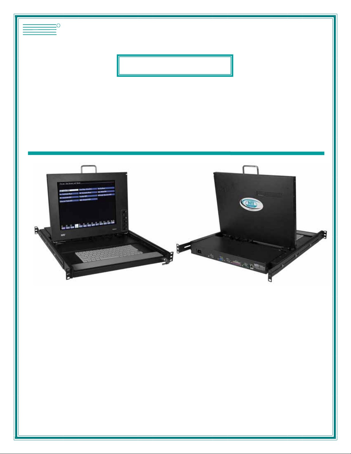
RACKMUX®Series
RACKMUX-T15
Rack Mount ANSI Terminal Drawer
Installation and Operation Manual
MAN029 Rev Date 10/18/2007
Page 2

TRADEMARK
RACKMUX is a registered trademark of Network Technologies Inc in the U.S. and other countries
COPYRIGHT
Copyright © 2004, 2007 by Network Technologies Inc. All rights reserved. No part of this publication may be reproduced, stored
in a retrieval system, or transmitted, in any form or by any means, electronic, mechanical, photocopying, recording, or otherwise,
without the prior written consent of Network Technologies Inc, 1275 Danner Drive, Aurora, Ohio 44202.
CHANGES
The material in this guide is for information only and is subject to change without notice. Network Technologies Inc reserves the
right to make changes in the product design without reservation and without notification to its users.
.
i
Page 3

TABLE OF CONTENTS
Introduction......................................................................................................................................................................1
Materials..........................................................................................................................................................................2
Features and Functions...................................................................................................................................................3
1. Installation ...................................................................................................................................................................4
1.1 Rack Mounting Instructions ...................................................................................................................................4
1.1.1 Standard Rack.................................................................................................................................................4
1.1.2 Optional Telco 2-Post Mounting......................................................................................................................5
1.2 Connect The Cables..............................................................................................................................................6
1.3 Power Up The Terminal.........................................................................................................................................7
2. Using The RACKMUX.................................................................................................................................................7
2.1 How To Setup The Terminal..................................................................................................................................7
2.1.1 Entering Setup.................................................................................................................................................7
2.1.2 Saving and Exiting Setup.................................................................................................................................7
2.1.3 Setup Directory................................................................................................................................................7
2.1.4 Default Configuration.......................................................................................................................................8
2.2 Changing The Operating Parameters....................................................................................................................9
3. Local Keyboard Commands......................................................................................................................................16
4. Connector Pin Assignment........................................................................................................................................17
5. Command Guide.......................................................................................................................................................18
5.1 Commands Supported in ASCII Personalities.....................................................................................................18
5.2 Variable Values for Table 10 Commands............................................................................................................25
6. ANSI Command Guide.............................................................................................................................................29
6.1 VT100, VT220 and Console ANSI Command Guide ..........................................................................................29
6.2 VT52 Command Guide........................................................................................................................................36
7. Using Printer Server in Ethernet Terminal ................................................................................................................37
Introduction................................................................................................................................................................37
7.1 Basic Setup.......................................................................................................................................................37
7.2 Setup for LPD ...................................................................................................................................................37
7.3 LPD printing......................................................................................................................................................38
7.4 Setup for TFTP.................................................................................................................................................39
7.5 TFTP Printing....................................................................................................................................................39
8. On-Screen Display (OSD).........................................................................................................................................40
8.1 Standard Controls................................................................................................................................................40
8.2 OSD Control Menu ..............................................................................................................................................40
8.2.1 OSD Main Menu............................................................................................................................................40
8.2.2 Brightness/Contrast Menu.............................................................................................................................41
8.2.3 Color Menu ....................................................................................................................................................41
8.2.4 Position Menu................................................................................................................................................41
8.2.5 Setup Menu....................................................................................................................................................42
9. Keyboard Functions ..................................................................................................................................................43
9.1 Function Key Operation.......................................................................................................................................43
9.2 Number Pad.........................................................................................................................................................44
9.3 Other Uses of the Function Key ..........................................................................................................................45
9.4 Numeric Keypad Option ......................................................................................................................................45
10. CPU-to-RACKMUX Ethernet Crossover Cable.......................................................................................................46
11. DC Power Option ....................................................................................................................................................47
Dimensional Drawings...................................................................................................................................................48
Frequently Asked Questions.........................................................................................................................................49
Technical Specifications................................................................................................................................................50
Troubleshooting.............................................................................................................................................................51
Index..............................................................................................................................................................................51
Warranty Information.....................................................................................................................................................51
ii
Page 4

TABLE OF FIGURES
Figure 1- Mount RACKMUX to rack...................................................................................................................................................4
Figure 2- Position RACKMUX with clearance to open.......................................................................................................................4
Figure 3- Mount to Telco post with optional mounting brackets.........................................................................................................5
Figure 4 -Connect a CPU to the RACKMUX......................................................................................................................................6
Figure 5- Connect to CPU using Ethernet cable................................................................................................................................6
Figure 6- Function keys to press for submenus.................................................................................................................................7
Figure 7- OSD Controls ...................................................................................................................................................................40
Figure 8- US (English) Keyboard Layout .........................................................................................................................................43
Figure 9- Keyboard LED Indications................................................................................................................................................ 43
Figure 10- Keys of the Number Pad ................................................................................................................................................44
Figure 11- Additional multi-function keys.........................................................................................................................................45
Figure 12- U.S. (English) keyboard with numeric keypad................................................................................................................45
Figure 13- U.K. (English) keyboard with numeric keypad................................................................................................................46
Figure 14- German keyboard with numeric keypad .........................................................................................................................46
Figure 15- RACKMUX with DC Power option..................................................................................................................................47
Figure 16- Apply wires to terminal block..........................................................................................................................................47
LIST OF TABLES
Table 1- Main Setup Menu Exit Functions.........................................................................................................................................7
Table 2- Programmable Keys..........................................................................................................................................................12
Table 3- Color Setup Menu..............................................................................................................................................................13
Table 4- Color Palettes....................................................................................................................................................................14
Table 5- Local Keyboard Commands in Native Mode......................................................................................................................16
Table 6- Serial Port (Serial 1) Connector Pin Assignments .............................................................................................................17
Table 7- Serial Port (Serial 2) Connector Pin Assignments .............................................................................................................17
Table 8- Printer Port Connector Pin Assignments ...........................................................................................................................17
Table 9- 10Base T Connector Pin Assignments..............................................................................................................................17
Table 10- Commands Supported in ASCII Personalities .................................................................................................................18
Table 11- VT52 Mode Escape Sequences ......................................................................................................................................36
Table 12- Number Pad Keys............................................................................................................................................................44
iii
Page 5

NTI RACKMUX RACKMOUNT ANSI TERMINAL DRAWER
INTRODUCTION
The RACKMUX-T15 (formerly referred to as RACKMUX-TERMINAL) Rack Mount ANSI Terminal Drawer (RACKMUX) places a
VTxx/ANSI Terminal right in the rack for space-saving, convenient control of SUN or PC-based headless servers. This LCD
monitor terminal drawer eliminates the need for an external laptop or table-top dumb terminal. This flexib le terminal is easy to
install and configure for either of the following communicatio n modes:
RS232 Terminal (using a RS-232 port for serial console connection). Use this configuration of the RACKMUX with the NTI
SERIMUX™ Console Serial Port Switch to control multiple servers.
Telnet Terminal (using an RJ45 10Base-T network port for Ethernet telnet console connection). The Ethernet connection can be
used with any 10Mb-compatible Ethernet host adapter, but is most suited for use with RSC (Remote System Control) Ethernet
ports, since these provide the same functionality as serial (ttya) console ports. This connection supports up to 12 telnet sessions
to different servers. The state of each server session is preserved by the terminal. Terminal sessions can be switched via hotkeys. When using the Ethernet telnet connection, the Terminal Drawer can be connected to multiple servers via an Ethernet
switch. However, it is advisable that the network used to connect the server consoles remains private for security reasons.
Note: Both RS232 serial and Ethernet telnet connections cannot be active at the same time.
This general purpose character terminal drawer offers full transaction capabilities and is largely pre-configured for most
applications. It was designed in conjunction with SUN Microsystems to ensure flawless compatibility with all SUN servers. It is also
compatible with most racks, including the Sun StorEdge 72", Sun Fire rack, and most EIA 19" racks. This console drawer is the
ideal solution for controlling web servers, DNS servers, mail servers and other equipment that lack video card capability, such as
the SUN Netra systems and HP servers.
The RACKMUX Terminal drawer is also available with an integrated console switch (RACKMUX-T15-RS16 or RACKMUX-T15SS8). See our website for details.
Features
• Entire unit is only 1U (1.75") high
• High-quality metal construction (ideal for most industrial and commercial settings)
• 15" TFT Rack Mount flip-up LCD Monitor features a wide viewing angle
• Screen size: 80x24 characters plus status line
• Keyboard lock prevents unauthorized use
• Auto shut-off switch: turns OFF power to the monitor when the LCD is folded closed
• Display format of 800x600
• LCD Display controls (using on-screen menu)
• 83-key (US) or 84-key (UK, German, French, Italian, Spanish) keyboard with wrist pad
• Supports RSC capabilities
• Serial and parallel slave-printer ports
• Includes rack mount kit suitable for SUN and most EIA 19" racks (fits 22" to 39" rack depths via adjustable mounting
brackets
• Optional support for mounting in a two-post Telco rack
• Optional protective anti-glare, tempered glass shield
• Internally mounted AC power supply or optional 48VDC power input
• Locking rails to prevent movement of the drawer when fully extended
Multiple RS-232 Emulations:
• ADDS A2 • VT100
• PC TERM • VT220
• PCG Alpha • WY-50+
• Console ANSI • WY-60
• TVI910+ • WY-100
• TV1925 • WY-120
• VT52 • WY-325
Compatibility
• Compatible with any SUN or PC-based headless server.
• Communicates with routers, bridges, firewalls, and hubs
)
1
Page 6

NTI RACKMUX RACKMOUNT ANSI TERMINAL DRAWER
Options
• LCD anti-glare protective glass shield - add a "G" to the model when ordering (i.e. RACKMUX-T15G)
• Telco 2-post style mounting kit- order RL-T15-TEL
• DC Power option- for use with 36-72VDC input- add “48V” to the part number (i.e. RACKMUX-T1548V)
• Numeric keypad option- for a separate 17-key numeric keypad, add “-N” to the part number (i.e. RACKMUX-T15-N)
See our catalog, visit our website at http://www.networktechinc.com
RGB-TECH) or 330-562-7070 for more details.
, or contact an NTI sales representative at 800-742-8324 (800-
MATERIALS
Materials Supplied with this kit:
• NTI RACKMUX-T15 Rack Mount ANSI Terminal Drawer
• VEXT-1,5-MM 1-1/2 foot 15HD VGA male-male cable
• 9DF25DM-NUL-6 6 foot DB9 female to DB25 male null modem cable
• IEC Power Cord, country specific
• 2 Keys for Lock
• 2 Rear Mounting Brackets w/nuts
• 8 #10-32x3/4” screws and cage nuts for mounting to a rack
2
Page 7
NTI RACKMUX RACKMOUNT ANSI TERMINAL DRAWER
12
Front View
RACKMUX-T15
14
11
16
17
18
19
13
201521
1
2
3
4
5
6
1
7
A
8
Rear View
RACKMUX-T15
Fn
9
10
22
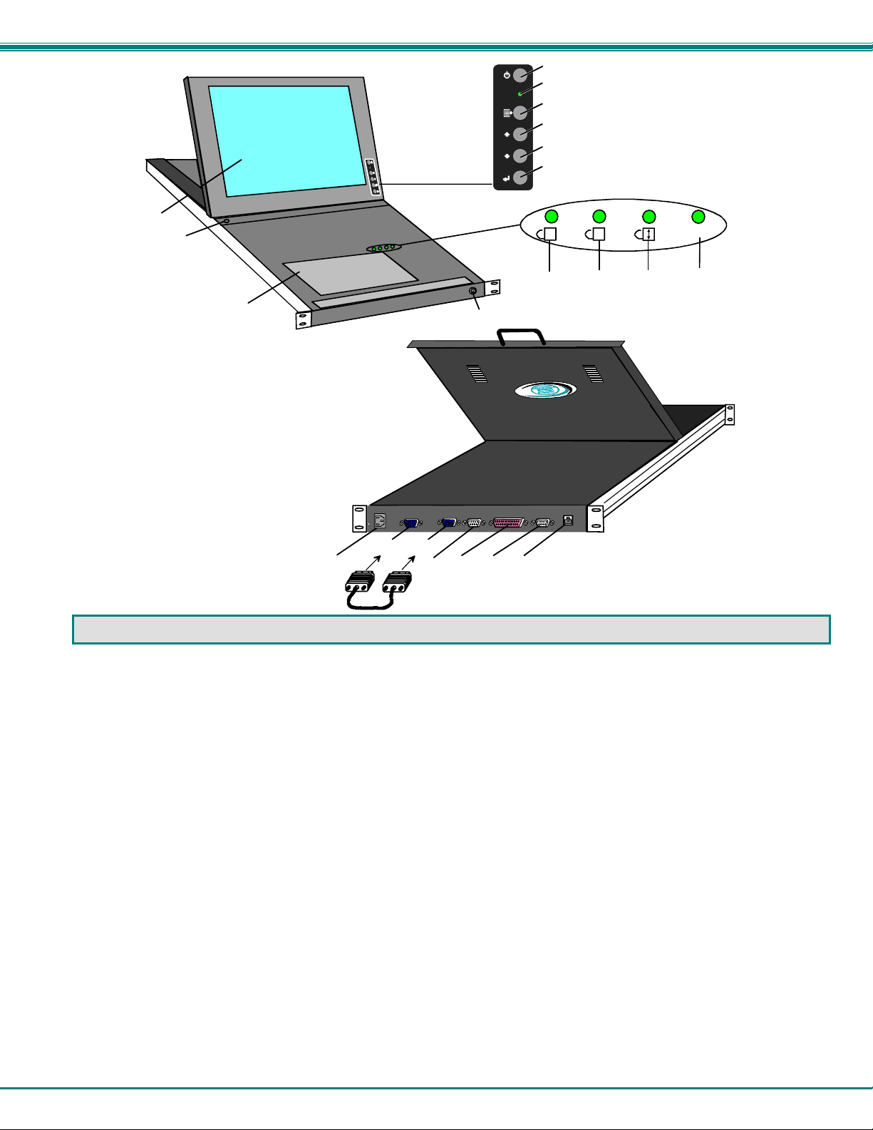
FEA TURES AND FUNCTIONS
1. Power Button- press to turn the LCD monitor ON and OFF
2. Power LED- indicates operation status
Green=Power-On, Video Input Signal OK
Red = Suspend / Stand-by, or no Video Input Signal
3. Menu Button- press to turn ON the OSD menu
4. Up Arrow Button- press to move the cursor in the OSD menu up
5. Down Arrow Button- press to move the cursor in the OSD menu down
6. Select Button- press to select a menu item (when OSD menu is ON) or press to auto adjust the video quality (when OSD
menu is OFF)
7. NumLock LED- illuminates when the number lock is ON
8. CapsLock LED- illuminates when CapLock is ON
9. Scroll Lock LED- illuminates when ScrollLock is ON
10. Fn LED- illuminates when Function Features (page 43) are enabled.
11. Keyboard- for manual data entry and computer control
12. LCD Display- for viewing the video signal from the connected CPU
13. Key Lock- to secure the keyboard in a closed position preventing unauthorized use
14. Auto Shut OFF Switch- automatically shuts OFF the LCD display when the monitor is folded down
15. IEC Connector- for attachment of the IEC power cord to power the keyboard and mouse
16. VGA- for connection of the VGA cable from the MONITOR port for the LCD display
17. Monitor- for connection of the VGA cable to support the LCD displ ay
18. Serial #2-male SUB D 9 connector- for attaching a local printer serially
19. Parallel- female SUB D 25 co nnector- for attaching local printer with parallel printer cable
20. Serial #1- male SUB D 9 connector- for attaching the serial interface cable from CPU
21. 10 Base T - female RJ45 connector- for connecting 10 Base-T Cat 5 Ethernet cable
22. VEXT-1,5-MM- 1-1/2 foot 15HD male-male VGA cable- to connect the VGA port to the Monitor port
3
Page 8
NTI RACKMUX RACKMOUNT ANSI TERMINAL DRAWER
t
1. INSTALLATION
1.1 Rack Mounting Instructions
1.1.1 Standard Rack
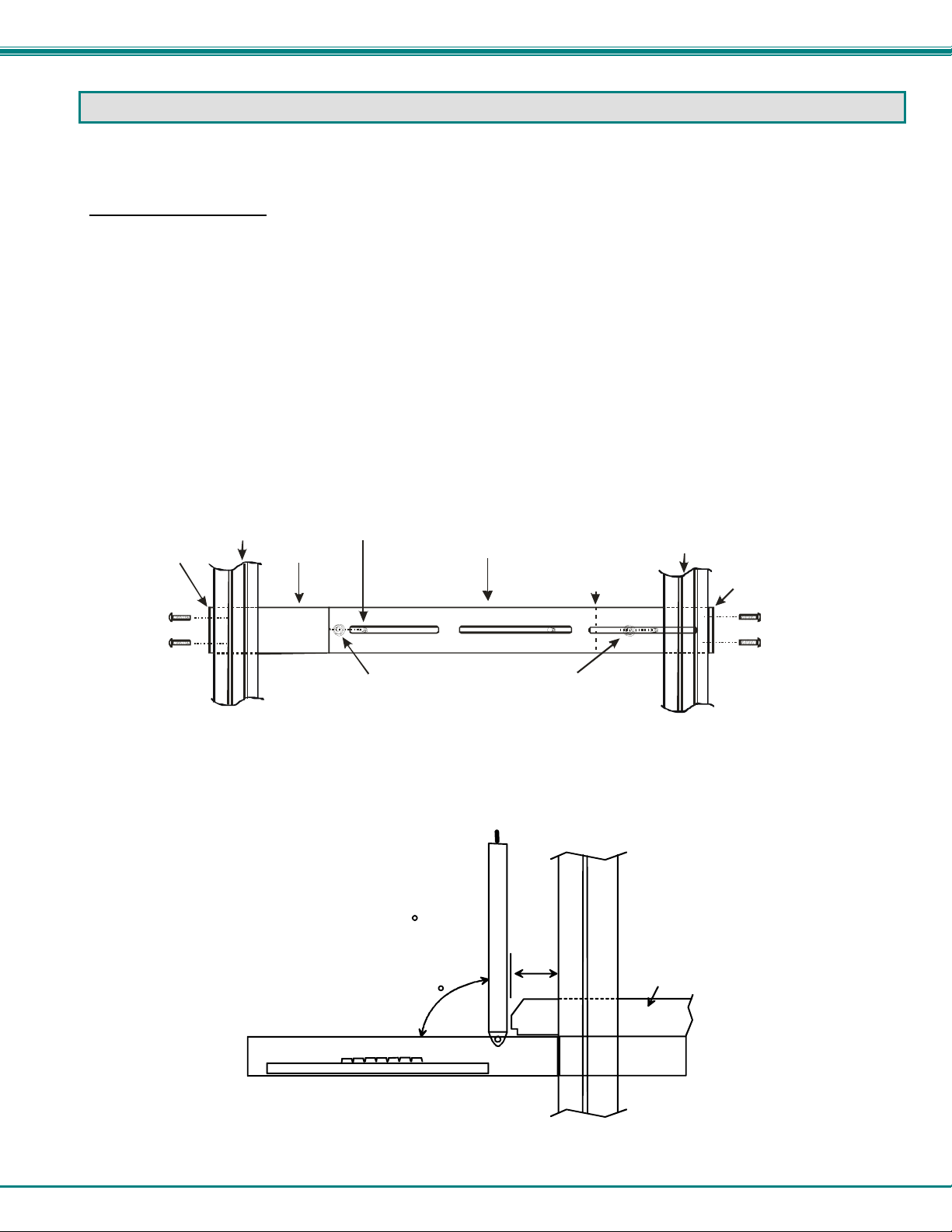
The RACKMUX was designed to be mounted to a rack and includes mounting flanges to make attachment easy.
1. Determine the mounting height in the rack for the drawer. It should be a height comfortable to use the keyboard and see the
LCD display. Mark holes in each of the 4 corner cabinet rails at points all level with each other.
2. Secure the rear brackets to the rear rack cabinet rails at the holes marked in step 1 using #10-32x3/4” screws and cage nuts
(supplied). Be sure to tighten the screws securely.
3. Lift the keyboard into position and line the studs on the left and right sides up with the slotted openings in the rear br acket.
Apply the nuts (supplied) to the studs but do not tighten the nuts yet.
FYI: There are 5 mounting studs provided on each side of the RACKMUX. Depending on the depth of the rack and
distance apart of the cabinet rails, the position of the rear bracket may make all 5 studs available for use. In this case,
apply the 2 nuts to the studs furthest apart from each other on each side.
4. Slide the drawer in until the top holes in the front bracket flanges line up with the holes marked in step 1. Secure the front
brackets on the drawer to the front cabinet rails using #10-32x3/4” screws and cage nuts (supplied). Be sure to tighten the
screws securely. Then tighten the nuts applied in step 3.
Front bracket
fl a nge on dra wer
Figure 1- Mount RACKMUX to rack
Note: To provide sufficient room for the LCD monitor to be opened to a p ro per viewing angle (a minimum 90 degree
position from the keyboard), ensure that all devices mounted above the RACKMUX extend no more than 1.75” from the
rack frame. (See Fig. 2)
Figure 2- Position RACKMUX with clearance to open
Front C abinet
Rail
Drawer
Stud on drawe r
Rear bracket overlapping
drawer
(Rear edge
of dra wer)
Apply nut s ( suppli ed) t o st uds a nd
secure rear brackets to drawer.
"X" must be
less than 1.75"
for LCD to open
to full 90
X
90
Side View of RACKMUX-T15
4
Re ar C abinet
Rail
Rear bracke
flange
Server mounted
above RACKMUX
in the same rack
Page 9
NTI RACKMUX RACKMOUNT ANSI TERMINAL DRAWER
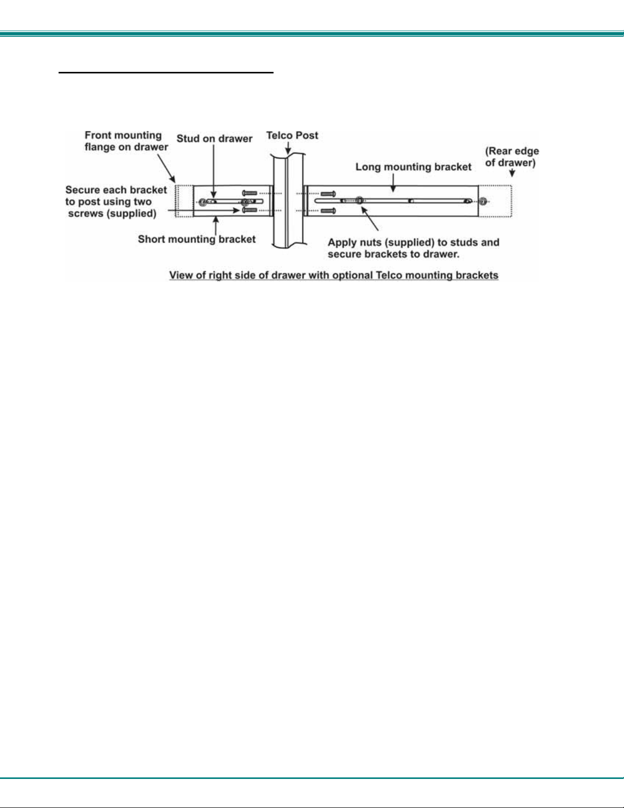
1.1.2 Optional Telco 2-Post Mounting
If the Telco 2-post mounting bracket kit (RL-T15-TEL) is to be used, secure the short and long brackets to each side of the drawer
as shown in Fig. 3. Apply 2 nuts (supplied) per bracket to secure the brackets to the drawer. Apply two #10-32x3/4” screws
(supplied) per bracket to the post at the desired height. Slots are provided in the brackets to make minor depth adjustments
easy. Be sure to properly tighten all nuts and screws before using the drawer.
Figure 3- Mount to Telco post with optional mounting brackets
5
Page 10
NTI RACKMUX RACKMOUNT ANSI TERMINAL DRAWER
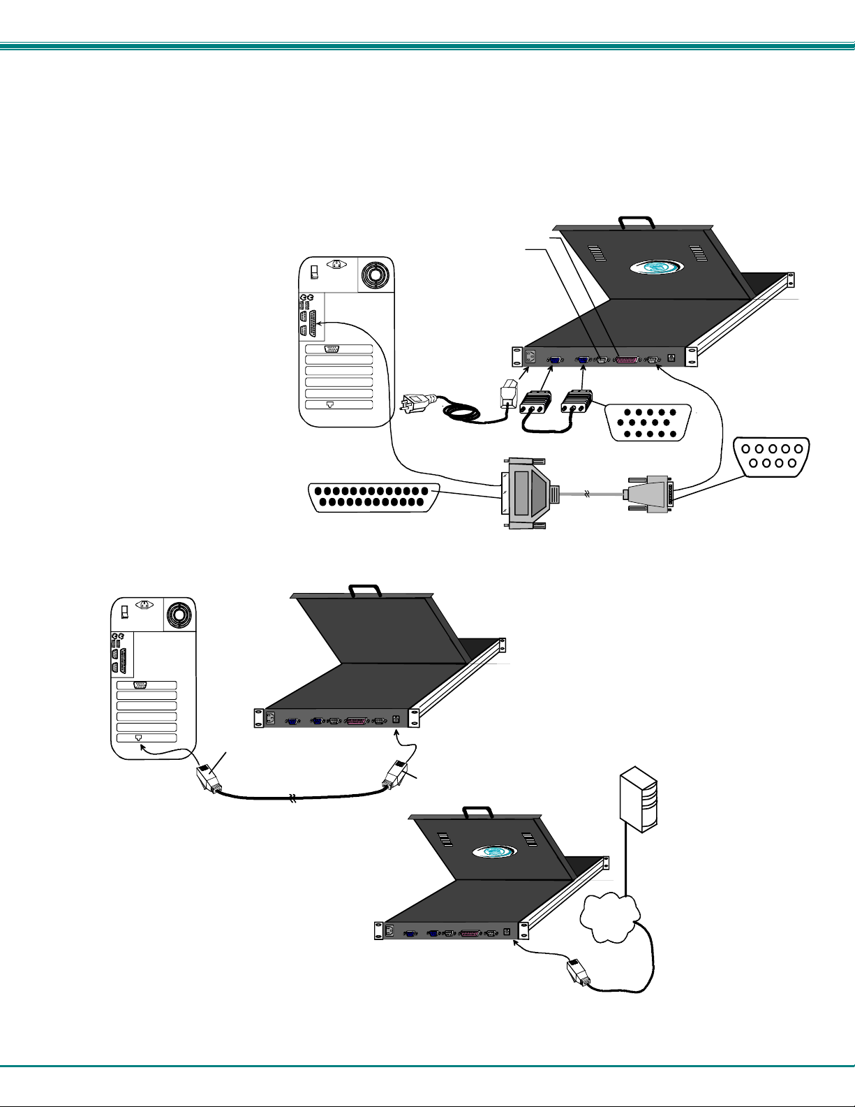
1.2 Connect The Cables
1. Connect a female SUB D 9 end of the null modem cable (supplied) to the "SERIAL 1" male SUB D 9 serial interface
connector on the RACKMUX (see Fig. 4).
2. Connect the other end of the null modem cable to a CPU.
Alternatively, use an Ethernet cable to connect to a CPU (see Fig. 5). For direct connection, use a crossover cable (see
pinout on page 46). For connection through a Local Area Network (LAN), use a patch cable wired straight through (pin
1 to pin 1, pin 2 to pin 2, etc.).
Note: A serial cable (Figure 4) and Ethernet cable cannot both be connected at the same time.
3. Connect the VEXT-1.5-MM cable between the
ports labeled "MONITOR" and "VGA".
4. If connecting a printer, connect
either a serial printer cable to
the remaining male SUB D 9
connector or a parallel printer
cable to the female SUB D 25
connector (see page 3, items
19 & 20).
5. Connect the IEC power cord to
the IEC connector.
Rear View of CPU
SUB D 25 male
connector
Figure 4 -Connect a CPU to the RACKMUX
Rear View of CPU
Server
male RJ45
connector
10Base T Ethernet Cable
(crossover cable)
Figure 5- Connect to CPU using Ethernet cable
Attach local printer
either by paral lel cable to Parallel
or by serial cable to Serial 2
IEC Powercord
(supplied)
VEXT-1,5-MM (supplied)
Rear View
RACKMUX-T15
male RJ 45
connector
15HD male
Video Connector
9DF25DM-NUL-6
(supplied)
Server
LAN
10Base T
Ethernet
Cable
(patch cable)
Rear View
RACKMUX-T15
SUB D 9 female
connector
6
Page 11
NTI RACKMUX RACKMOUNT ANSI TERMINAL DRAWER
1.3 Power Up The Terminal
1. Plug in to power ON the RACKMUX.
2. Using the key, unlock the drawer and slide the keyboard and LCD Display out far enoug h to raise the display to a comfortable
viewing angle.
3. Adjust the screen's brightness and contrast with the controls located on the monitor– as needed (see page 40).
2. USING THE RACKMUX
2.1 How To Setup The Terminal
The RACKMUX is compatible with most CPUs and application packages. A menu driven setup system is provided
to select and save the settings required by the CPU and application. A user must be familiar with the requirements of
the CPU in order to setup the RACKMUX.
2.1.1 Entering Setup
Hold down the <ALT> key and then depress the <Esc> key to enter Setup mode. When entering Setup, any text on the screen
temporarily disappears, and the main SETUP directory appears (See Figure 6). When leaving the Setup mode, the main SETUP
directory disappears, and any text that was on the screen will reappear.
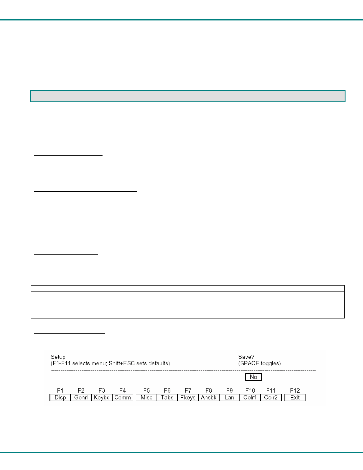
2.1.2 Saving and Exiting Setup
The first menu seen when entering Setup serves as a directory to the other Setup menus. To exit Setup or any submenu, press
<F12>. Pressing <F12> will return the display to the main Setup directory and with another press of <F12> the user will be given
the option of saving the selections made.
The highlighted field at the right of the screen gives the user the choice of saving or not saving parameter chang es in the
memory before returning the terminal to the normal operating mode.
NOTE: If settings are not saved before leaving the Setup mode, any new selections will be lost when the RACKMUX is
powered-down.
To save Setup selections, depress the Spacebar to change the save field at the right side of the screen from NO to YES before
exiting Setup. (Table 1 describes your options on exiting Setup.)
Depress <F12> to leave Setup and return to the normal display mode.
Table 1- Main Setup Menu Exit Functions
Option Function
No Returns terminal to normal operating mode without saving parameter changes for power up
Yes
Shift + Esc
Saves all changes (operating parameter, tabs, key definition, and answerback message); returns terminal
to its normal operating mode.
Restores all setting (operating parameters, tabs, key definitions, and answerback message) to default values.
2.1.3 Setup Directory
The fields at the bottom of the screen (Figure 6) show the various setup menus where the terminal's operating parameters can be
changed and the function key to press to immediately display any menu.
Figure 6- Function keys to press for submenus
7
Page 12

NTI RACKMUX RACKMOUNT ANSI TERMINAL DRAWER
2.1.4 Default Configuration
The terminal is delivered pre-configured with the following settings suitable for most RS232 serial console connections at 9600
baud using VT-100 emulation.
Disp SETUP Menu
Columns = Econ-80
Cursor = Blink Block
Screen Saver = Off
Lines = 24
Background = Dark
Page Length = 1 x Lines
Auto Page = Off
Width change clear = Off
ANSI Reverse = Off
Display= LCD
F4 Comm SETUP Menu
Baud rate = 9600
Data / Stop Bits = 8/1
Parity = None
Rcv Hndshake = Xon/Xoff
Xmt Hndshake = Xon/Xoff
Comm Mode = FDX
XPC Handshake = On
Printer Selection = Off
Multiple Sessions = Off
Ethernet Mode = Off
Auto Connect = Off
For use with an Ethernet connection the following parameters need to be configured:
• Display Setup (F1 in setup mode)
Page Length = 1*Lines (only required if ‘Multiple Sessions=On’)
• Communications Setup (F4 in setup menu)
Multiple Sessions = Off or On
Ethernet Mode = On
Auto Connect = Off or On
‘Multiple Sessions=On’ should be set if multiple telnet sessions are required.
‘Auto Connect=On’ is used to prevent the need to press return to establish a telnet connection.
• LAN Setup (F9 in setup mode)
Local IP Address = IP address of the terminal
Netmask = Netmask value for the network
Gateway = gateway address if required by the network
Remote IP 0 Address = IP address of first server Port = 23
Remote IP 1 Address = IP address of second server Port = 23
….
Remote IP B Address = IP address of twelfth server Port = 23
Term Type = Same as personality specified in General Setup menu
Ethernet Node ID = leave at default value
Note: If only one host is being connected to, all twelve Remote IP addresses and ports should be set to the same value.
Note: Eight separate telnet sessions are allowed if any columns other than Econ-80 is selected in Terminal Display Set-
up. If Econ-80 is selected, the Multiple Sessions option allows twelve concurrent telnet sessions to be used.
F2 General SETUP Menu
Personality = VT 100
Enhance = On
Status Line = Standard
Scroll Speed = Jump
Auto Scroll = On
End of Line Wrap = On
Rcvd CR = CR
Monitor = Off
Attribute = Char
F5 Misc SETUP Menu
Wprt Intensity = Dim
Wprt Reverse = Off
Wprt Underline = Off
Block End = US/CR
Ptr Baud rate = 38400
Ptr Data/Stop Bits = 8/1
Ptr Parity = None
Ptr Rcv Hndshake = Xon/Xoff
Ptr Xmt Hndshake = Xon/Xoff
Ptr Rcv = Off
F3 Keybd SETUP Menu
Keyclick = Off
Key Repeat = 5
Xmt Limit = None
Margin Bell = Off
Language = US
Keycode = ASCII
NRC = Off
Bell Volume = 2
NUM Start = Off
DEL Keypad = Dot/Del
F9 Lan Setup Menu
Local IP Address = {blank}
Netmask = {blank}
Gateway = {blank}
Remote IP 0..B Address ={blank}
Port 0...B = 23
Term Type = vt100
Ethernet Node ID = (default}
8
Page 13

NTI RACKMUX RACKMOUNT ANSI TERMINAL DRAWER
2.2 Changing The Operating Parameters
To select one of the setup menus shown, press the indicated function key.
- The screen for that menu appears with the name highlighted.
- The fields in the middle of the screen indicate the parameters that can be changed in that menu.
- The top line identifies the keys to press to highlight the parameter fields and change the settings.
The procedure is: (1) Use arrow key to highlight the parameter field to be changed.
(2) Use the Spacebar to change the parameter.
<F12> always returns the user to the top menu.
The following tables list the parameters for each menu and explain their settings. Default settings are listed first
unless otherwise noted.
F1- Disp SETUP Menu
-----------------------------------------------------------------------------------------------------------------------------------------------------
Columns sets the screen display for 80 columns, 132 columns, or Econ-80 (80 columns with more pages of memory).
Lines sets the screen display for 24, 25, 42, or 43 lines. (24 lines are normally required for VT emulation, 25 lines for PC Term.)
Auto Page on causes a new page of memory to move onto the screen when the cursor reaches the top or bottom of the page.
Display CRT/LCD selects which kind of monitor be used. If LCD monitor is selected, the display columns only support 80
columns on Econ-80 columns. Must be set to LCD.
Cursor sets the cursor display to blink or steady, block or underline.
Background sets the screen display to Dark (light chars. on a dark background) or Light (dark chars. on a light background).
Width Change Clear causes the terminal to clear the screen when executing a command to change the number of columns.
Screen Saver OFF, 1, 2, 3, 4, 5, 6. Sets the screen saver to activate after the specified number of minutes.
Page Length sets the length of a page of display memory to:
• 1 x Lines: Equal to the number of lines selected in the lines parameter (this value must be set when using multiple
sessions)
• 2 x Lines: Two times the value of the lines parameter
• 4 x Lines: Four times the value of the lines parameter, or
• *: Equal to the value of the lines parameter, with a second page containing the rest of the lines remaining in memory.
ANSI Reverse OFF/ON. Control function ANSI, VT-100 and VT-220:
• "OFF" means, when SGR command ESC [ 3? m and ESC [ 4? m select background and foreground color change
respectively.
• "ON" means, when SGR command ESC [ 3? m and ESC [ 4? m select foreground and background color change
respectively. (?
• can be 0,1,2,...,7)
F2- Genrl SETUP Menu
----------------------------------------------------------------------------------------------------------------------------------------------------Personality sets the terminal's operating mode to Wyse 325, Wyse 120/Wyse 60 (native mode), Wyse 50+ (WY-50, WY-50+,
WY-100, ADM 31/5/3a), TeleVideo TVI 925, TVI910+ (includes 910), ADDS A2, Digital Equipment VT-100, VT-220 7 bits,
VT-220 8 bits, VT-52, Console ANSI, PC TERM, PCG Alpha.
Scroll Speed sets the display scroll rate to Jump (the rate data is received), Smooth-8 (eight lines per second), Smooth-4,
Smooth-2, or Smooth-1.
Rcvd CR causes the cursor to move to the beginning of the current line (CR) or the beginning of the next line (CRLF) when the
terminal receives an ASCII CR.
Enhance allows the terminal to recognize an enhanced set of codes when the terminal is not in the native personality.
Auto Scroll causes the data to scroll up a line when the cursor moves past the last line of the page.
Monitor causes the terminal to display symbols for escape sequences and control codes without acting on them (test feature).
Status Line sets the top line of the screen as the status line.
9
Page 14

NTI RACKMUX RACKMOUNT ANSI TERMINAL DRAWER
End of Line Wrap causes the cursor to move to the start of the next line when additional characters are entered at the end of a
line.
Attribute sets display attributes to be assigned to each character as it is entered (Char), to be active to the end of the line (Line),
or to be active to the end of the page (Page).
-----------------------------------------------------------------------------------------------------------------------------------------------------
F3- Keybd SETUP Menu
-----------------------------------------------------------------------------------------------------------------------------------------------------
Keyclick sets the terminal to sound a muted beep each time a key is pressed or repeated.
Margin Bell sets the terminal's bell to ring when the cursor reaches the column where the bell is set (default is column 72 in 80-
column mode or 124 in 132-column mode).
NRC ON/OFF determines the communication and keyboard national character set.
DEL Keypad Dot/Del or Comma/Del. Determines whether numlock DEL generates dot or comma.
Key Repeat OFF, 1, .... ,8. Defines key repeat rate after a key has been depressed for about 1/2 second.
Language sets correct terminal operation for the language of the keyboard connected to it: US, UK, Danish, German, Spanish,
Swedish, Norwegian, Italian, French, Belgian, Swiss/French, and Swiss/German. Should be set to US.
Bell Volume OFF, 1, 2, 3 (3 different volumes)
Limit Xmt causes the terminal to send data through the HOST port as fast as the baud rate allows (None), or at a maximum rate
of 60 cps or 150 cps. In older systems limiting character rate is necessary to prevent loss of data.
Key Code sets the terminal to send normal ASCII characters (ASCII) or PC-type scan codes for every key up / down (Scan).
Scan is only required for the PC Term personality.
Num Start ON/OFF. When the terminal powers ON, this field determines whether the numeric pad starts as Numeric (NUM ON)
or Function (NUM OFF).
-----------------------------------------------------------------------------------------------------------------------------------------------------
F4- Comm SETUP Menu
----------------------------------------------------------------------------------------------------------------------------------------------------Baud Rate sets the host port baud rate to 50, 110, 134.5, 200, 300, 600, 1200, 2400, 4800, 7200, 9600, 19200, 38400, 57600,
76800, or 115200.
Rcv Hndshake allows the terminal to control the receipt of data from a device connected to the SERIAL1 port with no
handshaking (None), Xon / Xoff handshaking, DTR handshaking, DTR / Xoff handshakin g
XPC Hndshake ON/OFF to set XPC code handshake, only possible when the personality parameter is set to PC Term.
Ethernet Mode ON/OFF to set the communication routing by Ethernet Network / or Serial Port.
Note: Set to ON when using Telnet and OFF when using serial port communication.
Data / Stop Bits through the SERIAL1 port, the terminal to send and receive 8-bits data with one stop bit or two stop bits, or 7-
bits data with one stop or two stops bits.
Xmt Handshake causes the terminal, when sending data to a device connected to the SERIAL1 port, to ignore all incomin g
software handshaking signals (None) or to control data output in responds to Xon/Xoff handshaking.
Printer
Parallel : sends data to a parallel printer connected to the parallel port.
Serial : sends data to a serial printer connected to the serial 2 port.
OFF : ignores the print command.
Auto Connect OFF/ON selects whether a return character is required to establish an Ethernet connection.
Parity sets the terminal send data to the SERIAL1 (printer) port with none, odd, mark, even, or space parity.
Comm Mode sets the SERIAL1 port communication mode to full duplex (FDX), block (BLK), half duplex (HDX), or half duplex
block (HBLK).
Multiple Sessions defines whether an Ethernet connection supports multiple sessions function.
ON : indicates the terminal supports multiple sessions. Each session only has one display page. In 80 or 132 column mode, 8
simultaneous sessions are supported. In Econ-80 column mode, 12 simultaneous sessions are supported.
OFF : indicates the terminal only has single session. In this mode page length greater than one page can be defined.
10
Page 15

NTI RACKMUX RACKMOUNT ANSI TERMINAL DRAWER
-----------------------------------------------------------------------------------------------------------------------------------------------------
F5- Misc SETUP Menu
-----------------------------------------------------------------------------------------------------------------------------------------------------
Wprt Intensity sets the write protect attribute: normal, blank, dim, blank/dim.
Block End causes the terminal to send a block of data to the CPU with a line terminator as an ASCII US character and block
terminator as an ASCII CR character (US / CR), or with line terminators as ASCII CR and LF characters and the block terminator
as an ASCII ETX character (CRLF / ETX).
Ptr Parity causes the terminal to send the data to the SERIAL 2 (printer) port with none, odd, mark, even, or space parity.
Printer RCV ON/OFF
Wprt Reverse sets the write-protected characters to appear in reverse (dark characters on a light backgroun d).
Ptr Baud rate sets the SERIAL 2 (printer) port baud rate to 75, 150, 300, 600, 1200, 2400, 4800, 7200, 9600, 19200, 38400,
57600, 76800, 115200, 230400, 460800.
Ptr Rcv Hndshake sets the printer receive handshake through SERIAL 2 to be none, DTR, Xon / Xoff, DTR/Xoff .
Wprt Underline sets the write-protected characters to appear underlined.
Ptr Data/Stop Bits sets the data and stop bits through the SERIAL 2 (printer) port.
Ptr Xmt Hndshake sets the printer handshake to be none, DSR, Xon / Xoff, or Both .
-----------------------------------------------------------------------------------------------------------------------------------------------------
F6-Tabs SET-UP Menu
----------------------------------------------------------------------------------------------------------------------------------------------------On the tabs setup menu screen, the terminal's current tab stops are indicated by uppercase T's displayed alo ng a line of periods
that mark each column position.
(1) A tab stop in columns 2 through 78 is shown as a T in the upper line of periods
(2) A tab stop in columns 79 through 132 is shown as a T in the lower line of periods
The user can easily determine where tabs are set by moving the cursor across the line and reading the column number displ ayed
on the right side of the screen. Clear and set tabs anywhere on the line, as follows:
(1) To move the cursor across the line, press < →> (right arrow) or < ←> (left arrow)
(2) To either clear or set (toggle) an individual tab stop at the cursor position, press <Spacebar>
(3) To clear all tabs, press <Home>
(4) To set tabs to the default setting (every eighth column), press <Backspace>
Note: A tab stop cannot be set to column 1.
-----------------------------------------------------------------------------------------------------------------------------------------------------
F7- FKeys SET-UP Definition Setup Menu
----------------------------------------------------------------------------------------------------------------------------------------------------The function keys and many of the editing keys can be redefined to send a unique character string of up to 64 characters. Keys
that are not programmed will send a default sequence, which is determined by the personality selected. Table 2 lists the
programmable keys.
To redefine a key:
1. Select the key to be redefined by pressing that key together with <Ctrl> . This highlights the key's definition field.
2. Press <↑ > (up arrow) to select the shifted or unshifted key definition field.
3. Enter the key definition (up to 62 characters) at the cursor position. Correct errors by pressing < ← >(left arrow) to delete
characters or <Home> to clear the definition.
4. If the user wants to change the key's direction, press <Enter> (on the numeric pad) until the desired choice appears.
Direction determines where the key data is transmitted:
- Remote: Sends data to the CPU only, regardless of the terminal's communication mode. (Until redefined, the
direction of all the programmable keys is remote.)
- Local: Sends data to the terminal only, regardless of the terminal's communication mode
- Normal: Sends data to the CPU and / or the terminal, depending on the terminal's communication mode
11
Page 16
NTI RACKMUX RACKMOUNT ANSI TERMINAL DRAWER
Table 2- Programmable Keys
Enhanced PC-Style Keyboard Enhanced PC-Style Keyboard
F1 through F12 ENTER (Both ENTER keys are programmable)
(UP ARROW) ESCAPE
(DOWN ARROW) HOME
(LEFT ARROW) INSERT
(RIGHT ARROW) PAGE DOWN
BACKSPACE PAGE UP
DELETE PRINT SCREEN
END TAB
-----------------------------------------------------------------------------------------------------------------------------------------------------
F8- Ansbk SET-UP Menu
----------------------------------------------------------------------------------------------------------------------------------------------------A message of up to 20 characters can be programmed to identify the terminal to the CPU. Enter the message at the cursor
position. Correct errors by pressing <
> (left arrow) to delete characters or <Home> to clear the message.
CONCEAL hides the answerback message, so it is not displayed in setup mode.
To save the message in nonvolatile memory, exit Setup mode with the YES option.
-----------------------------------------------------------------------------------------------------------------------------------------------------
F9- Lan Setup Menu
----------------------------------------------------------------------------------------------------------------------------------------------------This menu configures the terminal for Ethernet communication. Use of Ethernet communications provides the additional abil ity to
open multiple sessions (applications) on one or more CPUs/servers at the same time. Support of these extended features requires
the server to be configured to accept telnet connections.
Note: The Ethernet option in the F4 setup menu must be set to ON for the terminal to work in an Ethernet environment.
Local IP Address is the IP address assigned to this terminal. This must be a unique IP address. An example of this address is
200.200.200.10.
Netmask is a value generated by the system based on the IP address. The system administrator would have this information. An
example is 255.255.255.0
Gateway This IP address is used to communicate with other networks. If a gateway is not being used this option should be blank.
Remote IP 0...B Address are for any remote CPU, or devices, that the terminal will communicate with for a specific session.
These twelve remote IP addresses should all be identical if all communications will be with only one CPU. If Multi-session-ON in
the F4 menu has been selected, and there is more than one CPU on the system, the user must specify which CPU each session
will communicate with. To communicate with a different CPU for a future session, these settings must be changed.
Note 1: The Multi-session option allows 8 separate sessions if any emulation other than ECON-80 is selected. If ECON-80
emulation is selected, the Multi-session option will then allow 12 separate sessions.
Note 2: Port 23 is the telnet service by default.
Note 3: The terminal must be powered cycled after saving for these parameters to take effect.
Term Type allows definition of the terminal with up to 40 characters. If Term Type is empty the default type is sent to the CPU
by the system.
Ethernet Node ID displays the serial number of the hardware Ethernet interface device. This is a default value of the
manufacturer of the hardware device and should not be changed.
-----------------------------------------------------------------------------------------------------------------------------------------------------
F10- Colr1 Set-up Menu
----------------------------------------------------------------------------------------------------------------------------------------------------Selects the color palette to be used for each screen attribute. A text sample of the selected color is displayed next to each
selection. Attribute selections are listed below.
Normal
Dim
Blank
Blink
Blink Blank
Rev
Rev Blank
Rev Blink
Rev Blink Blank
Undl.
Undl. Blank
Undl. Blink
Undl. Blink Blank
Undl. Rev
Undl. Rev Blank
Undl. Rev Blink
Undl. Rev Blink Blank
12
Page 17
NTI RACKMUX RACKMOUNT ANSI TERMINAL DRAWER
-----------------------------------------------------------------------------------------------------------------------------------------------------
F11- Colr2 Set-up Menu
----------------------------------------------------------------------------------------------------------------------------------------------------The color functionality differs with emulation. In general VT100, VT220 and ANSI Console work with applications, which control
the color directly. The remaining personalities associate colors based on existing monochrome vid eo attributes. T his section will
define parameter selection based on personality selected.
Background = Will determine the color of the background screen under some conditions (16 colors).
Normal F.G. \ Normal B.G. = These fields allow the user to select the character and background color (16 colors) for data
entered on the display before the application defines the color display remotely.
Border Color = The color of the border around the edge of the screen.
Cursor = Will select the color of the cursor (16 colors).
Intensity F.G. \ Intensity B.G. = These fields allow the user to select the character and background color (16 colors) for
data entered on the display as Dim in ASCII emulation's and Bold in VT\ANSI emulation's before the application defines the color
display remotely.
Attribute = Bold/Blink
Color mode = Is automatically selected based on the emulation selected.
Color map = Applies in WY325 mode only and determines if the monochrome attribute Reverse or Blank will be used to map
monochrome attributes to color.
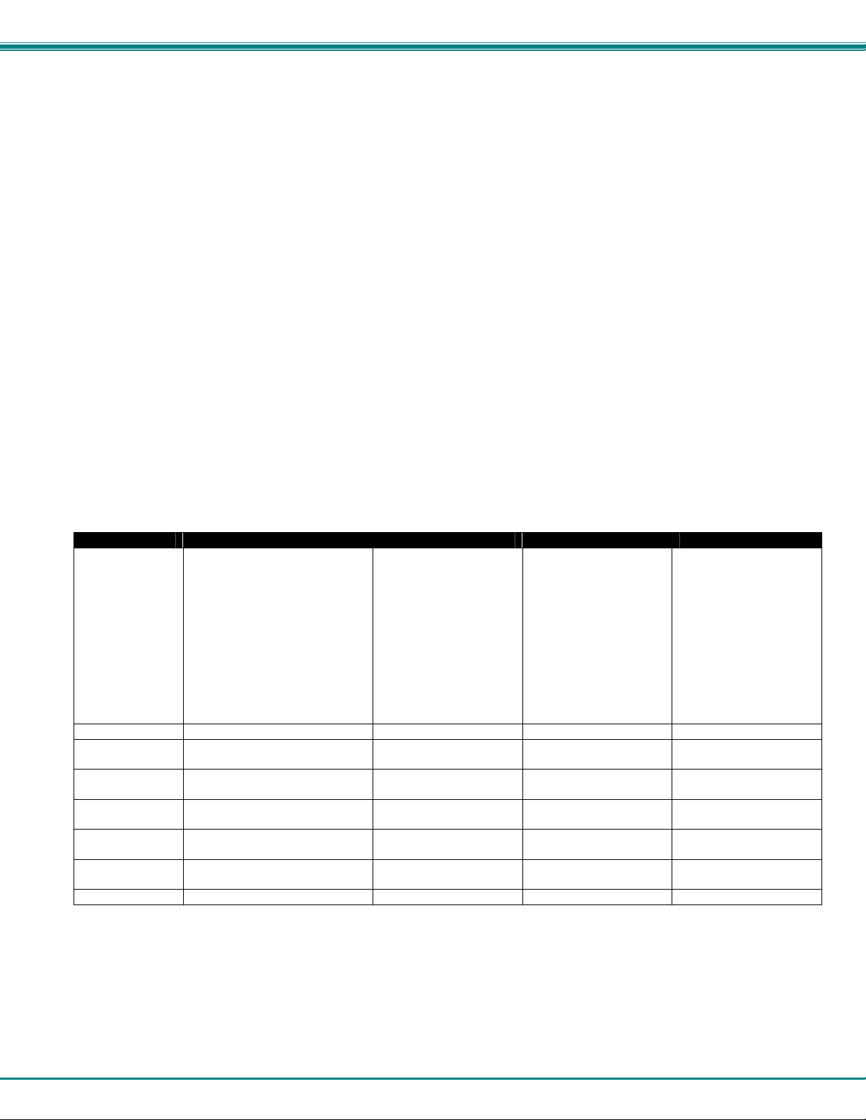
Color Association = OFF/ON
Table 3- Color Setup Menu
Option ASCII (NOT WY325) WY325 * VTXXX ANSI CONSOLE
Background =
Cursor =
Normal F.G. =
Normal B.G. =
Intensity F.G. =
Intensity B.G. =
Color Mode =
Normal/Palette
Color Map =
* When the WY 325 personality is selected holding the Ctrl key down and depressing either the 0, 1, ..., 9 or (.) period k eys in
the numeric pad change the assignment of color on the screen. Each selection is called a pal ette and is described in Table 4.
The whole data area of the
screen will be displayed in this
color, when the application
hasn't entered character or
spaces with the Normal or
Intensity B.G. color. Changes
in Background color will
affect Normal and Intensity
B.G. Any clear screen
commands will clear to this
color.
Selects Cursor color Selects Cursor color Selects Cursor color Selects Cursor color
Selects color of Normal F.G. No Function Initial color selection
Selects color of Normal B.G. No Function Initial color selection
Selects color of Intensity F.G. No Function
Selects color of Intensity B.G. No Function Initial color selection
Automatic Automatic Automatic Automatic
No Function See Above No Function No Function
No Function Same as ASCII Same as ASCII
Initial color selection
at power up
at power up
Initial color selection
at power up
at power up
at power up
Initial color selection
at power up
Initial color selection
at power up
Initial color selection
at power up
13
Page 18

NTI RACKMUX RACKMOUNT ANSI TERMINAL DRAWER
Table 4- Color Palettes
Palette Display Attribute Foreground Color Background Color
0
Normal
Reverse (or blank)
Intensity
*2
*1
Intensity*2 and reverse (or blank)
*1
Underline
Underline and reverse(or blank)
Underline and intensity
Underline, intensity,
1
Normal
Reverse (or blank)
Intensity
Intensity
*2
and reverse (or blank)
*2
*2,*3
and reverse (or blank)
*2
*1
*1
*1
Underline
Underline and reverse (or blank)
Underline and intensity
Underline, intensity,
2
Normal
Reverse (or blank)
*2,*3
and reverse (or blank)
*2
*1
*1
Intensity*2
Intensity
and reverse (or blank)
*2
*1
Underline
Underline and reverse (or blank)
Underline and intensity
Underline, intensity,
3
Normal
Reverse (or blank)
Intensity
Intensity
*2
and reverse (or blank)
*2
*2,*3
and reverse (or blank)
*2
*1
*1
*1
Underline
Underline and reverse (or blank)
Underline and intensity
Underline, intensity,
4
Normal
Reverse (or blank)
Intensity
Intensity
*2
and reverse (or blank)
*2
*2,*3
and reverse (or blank)
*2
*1
*1
*1
Underline
Underline and reverse (or blank)
Underline and intensity
Underline, intensity,
5
Normal
Reverse (or blank)
Intensity
Intensity
*2
and reverse (or blank)
*2
*2,*3
and reverse (or blank)
*2
*1
*1
*1
Underline
Underline and reverse (or blank)
Underline and intensity
Underline, intensity,
*2,*3
and reverse (or blank)
*2
*1
*1
*1
*1
*1
*1
*1
Green
Black
Blue
Black
Cyan
Black
Red
Black
Green
Black
Yellow
Black
Cyan
Black
White
Black
Cyan
Black
Red
Black
Magenta
Black
Blue
Black
Cyan
Black
White
Black
Magenta
Black
Yellow
Black
Magenta
Black
Blue
Black
Green
Black
Red
Black
Magenta
Black
White
Black
Green
Black
Cyan
Black
14
Black
Yellow
Black
Blue
Black
Cyan
Black
Red
Black
Red
Black
Yellow
Black
Cyan
Black
White
Black
White
Black
Red
Black
Magenta
Black
Blue
Black
Blue
Black
White
Black
Magenta
Black
Yellow
Black
Cyan
Black
Blue
Black
Green
Black
Red
Yellow
Black
White
Black
Green
Black
Black
Cyan
Page 19

NTI RACKMUX RACKMOUNT ANSI TERMINAL DRAWER
Table 4- Color Palettes (Cont'd)
Palette Display Attribute Foreground Color Background Color
6
7
8
9
10 (Soft Palette)
Normal
Reverse (or blank)*1
Intensity
Intensity
*2
and reverse (or blank)
*2
Underline
Underline and reverse (or blank)
Underline and intensity
Underline, intensity,
*2,*3
and reverse (or blank)
*2
Normal
Reverse (or blank)
Intensity
Intensity
*2
and reverse (or blank) *1
*2
*1
Underline
Underline and reverse (or blank)
Underline and intensity
Underline, intensity,
*2,*3
and reverse (or blank)
*2
Normal
Reverse (or blank)
Intensity
Intensity
*2
and reverse (or blank)*1
*2
*1
Underline
Underline and reverse (or blank)
Underline and intensity
Underline, intensity,
*2,*3
and reverse (or blank)
*2
Normal
Reverse (or blank)
Intensity
Intensity
*2
and reverse (or blank)
*2
*1
Underline
Underline and reverse (or blank)
Underline and intensity
Underline, intensity,
*2,*3
and reverse (or blank)
*2
Normal
(soft Reverse (or blank)
palette) Intensity
Intensity
*2
*2
and reverse (or blank)*1
*1
Underline
Underline and reverse (or blank)
Underline and intensity
Underline, intensity,
*2,*3
and reverse (or blank)
*2
*1
*1
*1
*1
*1
*1
*1
*1
*1
*1
*1
*1
Yellow
Black
Red
Black
Cyan
Black
Magenta
Black
Red
Yellow
Magenta
Black
Cyan
Black
Green
Black
White
Black
Red
Black
Yellow
Black
Magenta
Black
White
Black
Yellow
Black
Blue
Black
Cyan
Black
Green
Black
Blue
Black
Cyan
Black
Red
Black
*1. Whether the reverse or blank attribute is mapped to the colors shown depends on an escape sequence or the setting of
the Color Map setup parameter on the Attribute menu. The default is reverse. When the blank attribute is mapped, only the
background is visible.
*2. The intensity is dim in ASCII personalities and bold in ANSI personalities. (The intensity attribute is not supported in
the following personalities: Wyse 50+, ADDS A2, TVI 910+, TVI925, and VT52.) The attribute can be disabled by
an escape sequence or in setup mode (Intensity Attribute parameter).
*3. In each palette, the status line displays the same foreground and background colors as shown here for the underline-andintensity attribute.
Black
Yellow
Black
Red
Black
Cyan
Black
Magenta
Black
Red
Black
Magenta
Black
Cyan
Black
Green
Black
White
Black
Red
Black
Yellow
Black
Magenta
Black
White
Black
Yellow
Black
Blue
Black
Cyan
Black
Yellow
Black
Blue
Black
Cyan
Black
Red
15
Page 20
NTI RACKMUX RACKMOUNT ANSI TERMINAL DRAWER
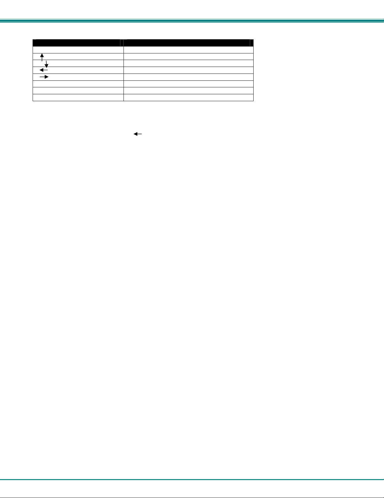
3. LOCAL KEYBOARD COMMANDS
Table 5 lists local keyboard commands in the terminal's native mode.
Table 5- Local Keyboard Commands in Native Mode
Key Sequence by keyboard Style
Command Enhanced PC
Toggle CAPS LOCK on/off CAPS LOCK
Toggle NUM LOCK on/off NUM LOCK
Put terminal in SETUP mode ALT ESC
Partially reset terminal, including communication unlock
keyboard, turn off all print modes
Send break*1 BREAK*2
Toggle between block and full-duplex modes SHIFT BREAK
Print Screen formatted PRINT SCREEN
Turn auxiliary print mode on/off
Turn monitor mode on/off CTRL SHIFT 1 (kpd)
Turn status line display on/off CTRL
Speed scrolling rate CTRL SHIFT
Slow scrolling rate CTRL SHIFT
Home cursor and clear page CTRL SHIFT HOME
Display page 0 CTRL 0kpd
Display page 1 CTRL 1kpd
Display next page (or active other window)
Display previous page (or active other window)
Toggle between split screen
and full screen format CTRL SHIFT –kpd
*5
*4
*5
Toggle Session 0*6
Toggle Session 1*6
Toggle Session 2*6
Toggle Session 3*6
Toggle Session 4*6
Toggle Session 5*6
Toggle Session 6*6
Toggle Session 7*6
Toggle Session 8*6
Toggle Session 9*6
Toggle Session A*6
Toggle Session B*6
Close the active Session by Local Terminal
*6
*1. To MODEM port only when configured as data port: has no effect on AUX port.
*2. [BREAK] = [PAUSE] pressed together with [CTRL].
*3. [SYS REQ] = [PRINT SCREEN] pressed together with [CTRL].
*4. If screen is split.
*5. Splits screen at line 12.
*6. Only active at Ethernet mode ON.
ALT PAUSE
SHIFT SYS REQ*3
PAGE DOWN
PAGE UP
ALT F1
ALT F2
ALT F3
ALT F4
ALT F5
ALT F6
ALT F7
ALT F8
ALT F9
ALT F10
ALT F11
ALT F12
CTRL SHIFT. Kpd
16
Page 21
NTI RACKMUX RACKMOUNT ANSI TERMINAL DRAWER
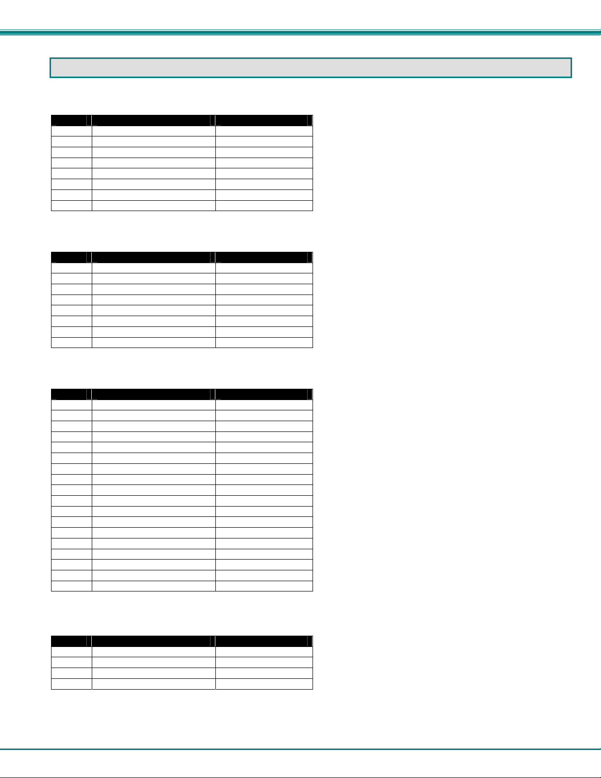
4. CONNECTOR PIN ASSIGNMENT
Table 6- Serial Port (Serial 1) Connector Pin Assignments
(RS232C 9-pin connector)
Pin Signal Mnemonic Direction
1
2
3
4
5
6
7
8
Table 7- Serial Port (Serial 2) Connector Pin Assignments
(RS232C 9-pin connector)
Pin Signal Mnemonic Direction
1
2
3
4
5
6
7
8
Table 8- Printer Port Connector Pin Assignments
(Compatible with the IBM PC parallel port)
Pin Signal Mnemonic Direction
1
2
3
4
5
6
7
8
9
10
11
12
13
14
15
16
17
18-25
Table 9- 10Base T Connector Pin Assignments
(RJ45 8 pin female connector)
Pin Signal Direction
1
2
3
6
Data carrier detect DCD In
Receive data RxD In
Transmit data TxD Out
Data terminal ready DTR Out
Signal ground SGND
Data set ready DSR In
Request to send RTS Out
Clear to send CTS In
Data carrier detect DCD In
Receive data RxD In
Transmit data TxD Out
Data terminal ready DTR Out
Signal ground SGND
Data set ready DSR In
Request to send RTS Out
Clear to send CTS In
-Strobe Out
Data bit 0 Out
Data bit 1 Out
Data bit 2 Out
Data bit 3 Out
Data bit 4 Out
Data bit 5 Out
Data bit 6 Out
Data bit 7 Out
-Acknowledge
Busy
Paper end
Slct
-Auto feed XT
-Error
-Init
-Slctn
Ground
Transmit + Out
Transmit - Out
Receive + In
Receive - In
In
In
In
In
Out
In
Out
Out
Out
17
Page 22
NTI RACKMUX RACKMOUNT ANSI TERMINAL DRAWER
5. COMMAND GUIDE
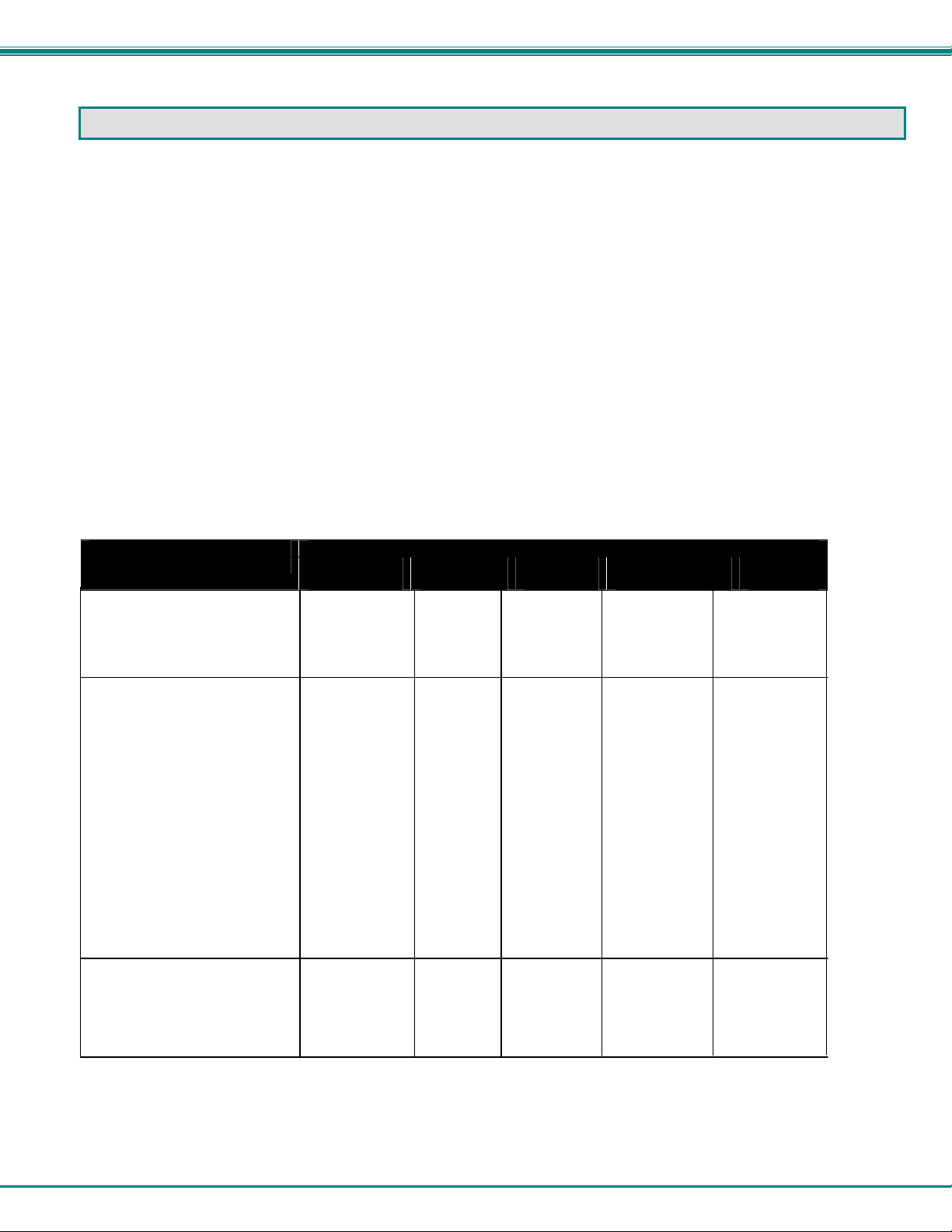
5.1 Commands Supported in ASCII Personalities
Table 5-1 lists all the ASCII commands recognized by the terminal. The native mode code for the command is given in the secon d
column. (The native mode includes WY-325,WY-120 and WY-60.) The remaining columns show the support for the command in
other ASCII personalities according to the following notations:
Same
Same as native code (code is native to other terminal also)
Wyse
Same as native code (Wyse enhancement- code not native to other terminal)
ENH
Same as native code when enhance mode is ON (Wyse enhancement - code not native to other terminal) A code listed under a
nonnative personality indicates that the related terminal's native code is supported.
A blank in any column indicates that the command is not supported.
Variables are shown in italics. Their values are listed in alphabetical order at the end of the table.
Footnotes are found at the end of Table 10 on page 20.
Table 10- Commands Supported in ASCII Personalities
Command
FUNCTION Native
Mode
Monitor Mode
Monitor mode on ESC U Same Same Same
Monitor mode off ESC u Same Same Same
or ESC X Same
Selecting Personalities
Enhance mode off ESC ~ SPACE Same ENH ENH ESC v SPACE
Enhance mode on ESC ~ ! Same ENH ENH ESC v !
Select WY-50+ mode ESC ~" Same ENH Wyse ESC v "
Select TVI 910+ mode ESC ~ # Same ENH Wyse ESC v #
Select TVI 925 mode ESC ~ $ Same ENH Wyse ESC v $
Select ADDS VP A2 mode ESC ~ % Same ENH Wyse ESC v %
Select Console ANSI mode ESC ~ A Same ENH Wyse ESC v A
Select Native mode ESC ~ 4 Same ENH Wyse ESC v 4
Select PC Term mode ESC ~ 5 Same ENH Wyse ESC v 5
Select VT52 mode ESC ~ 6 Same ENH Wyse ESC v 6
Select VT100 mode ESC ~ ; Same ENH Wyse ESC v ;
Select PCGAPHIC mode
Select VT220-7 mode ESC ~ < Same ENH Wyse ESC v <
Select VT220-8 mode ESC ~ = Same ENH Wyse ESC v =
Select WY-325 mode
Communicating with the
computer
Enable transmission CTRL Q Same Same Same Same
Stop transmission Disconnect CTRL S Same Same Same Same
Send ACK (if ACK mode on) CTRL E Same Wyse Same
ESC ~ I Same ENH Wyse ESC v I
*1
ESC ~ B Same ENH Wyse ESC v B
*3
Wyse
WY-50+
ADDS
VP A2
TVI
910+/925
PC
Term
18
Page 23
NTI RACKMUX RACKMOUNT ANSI TERMINAL DRAWER
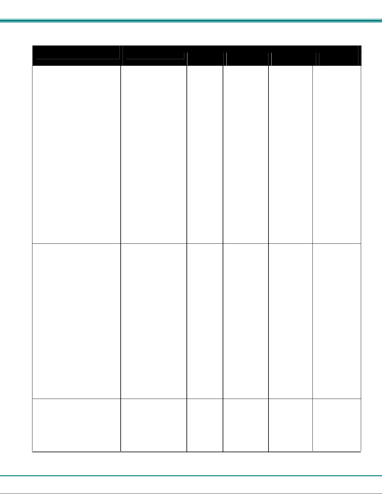
Table 10- Commands Supported in ASCII Personalities (Cont'd)
Command
FUNCTION Native Mode Wyse
WY-50+
ACK mode off ESC e 6 Same ENH
ACK mode on ESC e 7 Same ENH
Full-duplex mode on ESC C ESC D F Same Same ESC }
Half-duplex mode on ESC C ESC D H Same Same ESC {
Block mode on ESC B Same Same Same
Block mode off (conversation) ESC C
Half-duplex block mode on ESC D H ESC B Same Same ENH
Set Serial 1 port receive ESC c 2 hndshk Same ENH
handshaking protocol
Set Serial 1 port transmit ESC c 4 hndshk Same ENH
handshaking protocol
Set maximum data transmission ESC c 6 max
speed for host port
Set Serial 1 port operating ESC c 0 baud
parameters stop parity word
Set Serial 2 port operating ESC c 1 baud
parameters stop parity word
Enable DTR Serial port 1 CTRL N CTRL N CTRL N
Handshaking
Enable X-on/X-off Serial port 1 CTRL O CTRL O CTRL O
Program answerback message ESC c; answer Same ENH
CTRL Y
Conceal answerback message ESC c = Same ENH
Send answerback message ESC c < Same ENH
Turn answerback mode off ESC e SP Same ENH
Turn answerback mode on ESC e ! Same ENH
Controlling the Terminal and
Keyboard
Sound bell CTRL G Same Same Same Same
Select bell volume ESC c \volume Same ENH
Unlock keyboard CTRL N or ESC" Same CTRL B ESC " ESC "
Lock keyboard CTRL O or ESC# Same CTRL D Same ESC #
CAPS LOCK off ESC e ' ENH ENH ENH ESC SP M
CAPS LOCK on ESC e & ENH ENH ENH ESC SP L
NUM LOCK off ESC e @ ENH ENH ENH ESC SP K
NUM LOCK on ESC e A ENH ENH ENH ESC SP J
SCROLL LOCK off ESC e B ENH ENH ENH ESC SP O
SCROLL LOCK on ESC e C ENH ENH ENH ESC SP N
Keyclick off ESC e $ Same ENH ESC < ESC <
Keyclick on ESC e % Same ENH ESC > ESC >
Margin bell off ESC e L Same ENH ENH ESC n
Margin bell on ESC e M Same ENH ENH ESC o
Set margin bell at curs position ESC ' J Same ENH
Select standard ASCII key code ESC e H Same ENH
mode
Select PC scan code mode ESC e I Same ENH
Key repeat off ESC e , Same ENH ENH
Key repeat on ESC e - Same ENH ENH
Read keyboard status ESC [
Redefining the keys
Clear function key definition ESC z fkey Same
DEL
Clear key direction and definition ESC Z dir Same ENH
key/fkey DEL
ADDS
VP A2
TVI
910+/925
PC
Term
19
Page 24

NTI RACKMUX RACKMOUNT ANSI TERMINAL DRAWER
Table 10- Commands Supported in ASCII Personalities (Cont'd)
FUNCTION Native Mode Wyse
WY-50+
ADDS
VP A2
TVI
910+/925
PC
Term
-Program function key definition ESC z fkey Same ENH ENH
sequence DEL
Program key direction and ESC Z dir Same Wyse ESC | p1 p2
definition key/fkey sequence
sequence DEL CTRL Y
Read key direction and definition ESC Z ~key Same
or ESC Z ~fkey
Screen and Cursor Display
Screen display off ESC ` 8 Same ENH ESC o ESC O
Screen display on ESC ` 9 Same ENH ESC n ESC N
Screen saver off ESC e P Same ENH ENH
Screen saver on ESC e Q Same ENH ENH
Set reverse screen ESC ^ 1 Same ENH ESC b
Restore normal screen ESC ^ 0 Same ENH ESC d
*4
Set scrolling speed and type ESC ` scroll Same ENH
Smooth scrolling on ESC 8
Smooth scrolling off ESC 9
*5
*5
Set cursor display features ESC ` cursor Same ENH ESC . cursor1 ESC.cursor1
Cursor display off ESC ` 0 Same CTRL W
Cursor display on ESC ` 1 Same CTRL X
25th line display off ESC e
Displaying the Message Fields
Extended status line on ESC ` a Same ENH
Standard status line on ESC ` b Same ENH
Status line off ESC ` c Same ENH
Program/display CPU message ESC F Same ENH
on status line message CR
Program CPU message on ESC z ( text Same ENH ESC f
unshifted lable line
CR text CR text CR
*6
ESC f
*5
Program CPU message on shifted ESC z ) text Same ENH
label line CR
Turn off shifted label line ESC z DEL Same ENH ENH
Clear unshifted label line ESC z ( CR Same ENH
Clear shifted label line ESC z ) CR Same ENH ENH
Program/display function key label ESC z field Same ENH ENH
label CR
Clear function key label ESC z field Same ENH ENH
CR
Defining the data Area
Select 80-column display ESC ` : Same ENH
Select 132-column display ESC ` ; Same ENH
Economy 80-column mode off ESC e F Same ENH
Economy 80-column mode on ESC e G Same ENH
Width-change-clear mode off ESC e . Same ENH
Width-change-clear mode on ESC e / Same ENH
Display 24 data lines
Display 25 data lines
ESC e ( Same ENH
*7
ESC e ) Same ENH ESC ^
*7
20
Page 25
NTI RACKMUX RACKMOUNT ANSI TERMINAL DRAWER
Table 10- Commands Supported in ASCII Personalities (Cont'd)
FUNCTION Native Mode Wyse
WY-50+
ADDS
VP A2
TVI
910+/925
PC
Term
Display Memory/Split Screen
Divide memory into pages ESC w length Same ENH
Display previous page ESC w B or ESC J
Display next page ESC w C or ESC K
Same ENH ESC J
*8
Same ENH ESC K
*8
Display page n ESC w page Same ENH
Split screen horizontally ESC x A line Same
(simple split)
Split screen horizontally ESC x 1 line Same
(simple split) and clear pages
Split screen horizontally ESC x 3 line Same
(adjustable split) and clear pages
Split screen horizontally ESC x C line Same
(adjustable split)
Activate upper window ESC ] Same
Activate lower window ESC } Same
Activates other window (or page
) ESC J or ESC K Same ESC J
*8
*5
Lower horizontal split ESC x P Same
Raise horizontal split ESC x R Same
Roll window up in page ESC w E Same
Roll window down in page ESC w F Same
Redefine screen as one window ESC x @ Same
Redefine screen as one window ESC x 0 Same
and clear pages
Display Attributes
Assign display attribute to a ESC A mf attr Same ESC \
*4
message field
Assign character display attribute ESC G attr Same ENH Same Same
Character attribute mode off ESC e 0
Character attribute mode on ESC e 1
Page attribute mode on ESC e 2 Same
Line attribute mode on ESC e 3 Same
Assign write-protected character ESC `wpca Same ESC 0 wpca1
display attribute
Clear unprotected page to ESC ! ENH Wyse
display attribute attr
Assign line attribute ESC G lattr Same ENH
Redefine color map values
ESC d y
*9
fcolor
bcolor map
Set tag protect attribute CTRL N
Reset tag protect attribute CTRL O
Select a predefined color palette
ESC d z
*9
palette
Map blank attribute
Map reverse attribute
ESC d {
*9
ESC d |
*9
Protecting Data
Write-protect mode off ESC ( Same CTRL O Same Same
Write-protect mode on ESC ) Same CTRL N Same Same
Clear cursor column to ESC V Same ENH Same
write-protected spaces
Protect mode off ESC , Same ENH Same Same
Protect mode on ESC & Same ENH Wyse Same
21
Page 26

NTI RACKMUX RACKMOUNT ANSI TERMINAL DRAWER
Table 10- Commands Supported in ASCII Personalities (Cont'd)
FUNCTION Native Mode Wyse
WY-50+
Graphics Characters
Graphics mode on ESC H CTRL B Same ESC $ ESC $
Graphics mode off ESC H CTRL C Same ESC % ESC %
Display graphics character ESC H ldraw Same
Controlling the Cursor
Cursor left (backspace) CTRL H Same Same Same Same
or CTRL U
Cursor right CTRL L Same CTRL F Same Same
Cursor up; no scroll CTRL K Same CTRL Z Same Same
Cursor up; scroll (reverse linefeed) ESC j Same ENH Same
Cursor down; no scroll CTRL V CTRL V
Cursor down; scroll (Linefeed) CTRL J Same Same Same Same
Cursor to start of line CTRL M Same Same Same Same
Cursor to start of next line CTRL _ Same ENH Same Same
Home cursor ESC { Same ENH Wyse CTRL ^
or CTRL ^ or CTRL A Same
Cursor to specific column CTRL P col ESC ]
Cursor to specific line CTRL K line ESC [
End-of-line wrap off ESC d . Same ENH ESC 0
End-of line wrap on ESC d / Same ENH ESC ~
Received CR mode off ESC e 4 Same ENH ENH ESC 9
Received CR mode on ESC e 5 Same ENH ENH ESC 8
Autopage mode off ESC d * Same ENH ESC w
Autopage mode on ESC d + Same ENH ESC v
Autoscrolling mode off ESC N Same ENH
Autoscrolling mode on ESC O Same ENH
Address cursor in current ESC = line Same ENH Same Same
80-column page col or ESC Y
Address cursor in specific ESC w @ page Same ENH ESC - page
80-column page line col line col
Address cursor in specific ESC - wnd/ Same ENH Same
80-column window/page
Address cursor in specific ESC a lll R Same ENH Same
80/132-column current page ccc C
Read cursor line and column ESC ? Same ENH Same Same
address in 80-column current
page
Read 80-column page number ESC w Same ENH
and cursor address
Read 80-column window/page ESC / Same ENH Same Same
number and cursor address
Read cursor address in 80/132- ESC b Same ENH
column page
Editing
Clear all tab stops ESC 0 Same ENH ESC 3 ESC 3
Set tab stop ESC 1 Same ENH Same Same
Clear tab stop ESC 2 Same ENH Same Same
Tabulate cursor ESC i or CTRL I Same ENH CTRL I CTRL I
Backtab ESC I Same ENH Same Same
Field tab ESC I ESC i
Insert mode on, replace mode off ESC q Same ENH ENH ESC Z
Insert mode off, replace mode on ESC r Same ENH ENH Same
Insert space character ESC Q Same ENH Same Same
page line col
*8
ADDS
VP A2
TVI
910+/925
PC
Term
Same
*10
*11
22
Page 27

NTI RACKMUX RACKMOUNT ANSI TERMINAL DRAWER
Table 10- Commands Supported in ASCII Personalities (Cont'd)
FUNCTION Native Mode Wyse
WY-50+
Editing (Cont'd)
Insert line of spaces ESC E Same ENH Same Same
Delete cursor character ESC W Same ENH Same Same
Delete cursor line ESC R Same ESC l Same Same
Clearing Data
Clear page to nulls ESC * Same ENH Same Same
Clear page to spaces ESC + Same ENH
Clear page to write-protected ESC , Same ENH Same
spaces
Clear unprotected page to spaces ESC ; or CTRL Z Same ESC ; ESC ; Same
Clear unprotected page to nulls ESC : Same ENH Same Same
Clear unprotected page to ESC .char Same ENH
a specific character
Clear unprotected page to ESC ,
protected spaces
Clear unprotected page to ESC ! attr ENH ENH
display attribute
Clear unprotected page to spaces ESC Y Same ESC k Same Same
from cursor
Clear unprotected page to nulls ESC y Same ENH Same Same
from cursor
Clear unprotected line to spaces ESC T Same ESC K Same Same
from cursor
Clear unprotected line to nulls ESC t Same ENH Same Same
from cursor
Fill page with H's ESC F
Sending data
Begin print / send at top of page ESC d' Same ENH
Begin print / send at top of screen ESC d& Same ENH
Send cursor character ESC M Same
Send line through cursor ESC 6 Same Same ESC 6
Send unprotected line through ESC 4 Same Same ESC 4
cursor
Send page through cursor ESC 7 Same ENH Same ESC 7
Send unprotected page through ESC 5 Same Same ESC 5
cursor
Mark block beginning ESC 8 Same ENH
Mark block end ESC 9 Same ENH
Send entire block ESC s Same ENH Same Same
Send unprotected ESC S Same ENH Same Same
Report terminal status ESC [
Report attribute under cursor ESC D
23
ADDS
VP A2
ENH or ESC +
TVI
910+/925
PC
Term
Page 28

NTI RACKMUX RACKMOUNT ANSI TERMINAL DRAWER
Table 10- Commands Supported in ASCII Personalities (Cont'd)
FUNCTION Native Mode Wyse
WY-50+
Print Functions
Print formatted page ESC P Same ENH Same Same
Print formatted unprotected page ESC @ Same ENH
Print unformatted page ESC p or ESC L Same ESC p ESC L
Select Parallel printer ESC d ( Same Same
Select Serial printer ESC d ) Same Same
Auxiliary print mode off CTRL T Same Same ESC A ESC A
Auxiliary print mode on CTRL R Same Same ESC @
Transparent print mode off CTRL T Same ESC 4 ESC a ESC a
Transparent print mode on ESC d # Same ESC 3 ESC ` ESC `
Bi-directional mode off ESC d $ CTRL T CTRL T
Bi-directional mode on ESC d % CTRL CTRL R
Auxiliary receive mode off ESC d SPACE
Auxiliary receive mode on ESC d !
Set print terminator ESC p ESC p
Define delimiters ESC x ESC x
Character Sets
Select primary character set ESC c D Same
Select secondary character set ESC c E Same
Define primary character set ESC c B bank Same
Define secondary character set ESC c C bank Same
Load font bank with predefined ESC c @ bank Same
set
Clear font bank ESC c ? bank Same
Define and load character ESC c A bank Same
pp bb...bb
CTRL Y
*1. PCG ALPHA in Mono. Text Model machine.
*3. Valid only in Color Model machine.
*4. With enhance mode off.
*5. With enhance mode on.
*6. Automatically display in native mode. May be hidden by assigning blank attribute (ESC A l l).
*7. Screen cleared.
*8. If screen is not split.
*9. In WY-325 only
*10. In TeleVideo 925 only
*11. In TeleVideo 910+ only
24
ADDS
VP A2
TVI
910+/925
*11
PC
Term
Page 29

NTI RACKMUX RACKMOUNT ANSI TERMINAL DRAWER
5.2 Variable Values for Table 10 Commands
answer Up to 20 characters to define answerback message
attr
Display Attributes
attr
SPACE Space character p Dim
0 Normal q Dim and invisible
1 Blank r Dim and blink
2 Blink s Dim, blink, invisible
3 Blink and Blank t Dim and reverse
4 Reverse u Dim, reverse, invisible
5 Reverse and invisible v Dim, reverse, blink
6 Reverse and blink w Dim, reverse, blink invisible
7 Reverse, blink, invisible x Dim and underline
8 Underline y Dim, underline, invisible
9 Underline and invisible z Dim, underline, blink
: Underline and blink { Dim, underline, blink invisible
; Underline, blink, invisible | Dim, underline, reverse
< Underline and reverse } Dim, underline, reverse invisible
= Underline, reverse, invisible ~ Dim, underline, reverse blink
> Underline, reverse, blink DEL Dim, underline, reverse blink, invisible
? Underline, reverse, blink invisible
bank
Font Bank
bank
*a
Font Bank*a
0 Font bank 0 2 Font bank 2
1 Font bank 1 3 Font bank 3
*a Holds predefined character set
baud
Baud Rate
baud
Baud Rate
baud
Baud Rate
0 115200 4 19200 8 2400 < 200
1 76800 5 9600 9 1200 = 134.5
2 57600 6 7200 : 600 > 110
3 38400 7 4800 : 300 ? 50
bb...bb 32-byte character string defining bit pattern of character
bcolor
Background Color
bcolor
Background Color
1 Black 5 Red
2 Bue 6 Magenta
3 Green 7 Yellow
4 Cyan 8 White
ccc One-to three-decimal value of column relative to home
char Character that replaces unprotected characters
col See line/col
color
color
color
color
color
color
1 Black 6 Magenta D Dim cyan
2 Bue 7 Yellow E Dim red
3 Green 8 White F Dim magenta
4 Cyan B Dim blue G Dim yellow
5 Red C Dim green H Dim white
cursor
Cursor Display
cursor
Cursor Display
0 Cursor display off 3 Blinking line cursor
1 Cursor display on 4 Steady line cursor
2 Steady block cursor 5 Blinking b lock cursor
dir
Direction
0 Normal
1 Remote
2 Local
25
Display Attributes
baud
Baud Rate
Page 30

NTI RACKMUX RACKMOUNT ANSI TERMINAL DRAWER
Variable Values for Table 10 Commands (Cont'd)
fcolor
Foreground Color
fcolor
1 Black 5 Red
2 Bue 6 Magenta
3 Green 7 Yellow
4 Cyan 8 White
Function
Key
field
unshifted
field
shifted
F1 0 P F7 6 V
F2 1 Q F8 7 W
F3 2 R F9 8 X
F4 3 S F10 9 Y
F5 4 T F11 : Z
F6 5 U F12 ; [
Function
Key
fkey
unshifted
fkey
shifted
F1 @ ` F7 F f
F2 A a F8 G g
F3 B b F9 H h
F4 C c F10 I i
F5 D d F11 J j
F6 E e F12 K k
hndshk
Handshaking Protocol
Receive Transmit
0 None (default) None (default)
1 XON/XOFF XON/XOFF
2 DTR
3 Both
Keyboard Style
key
Enhanced PC
key
SPACE ESC & SHIFT TAB → $ RETURN
% SHIFT ESC " ← BACKSPACE ) SHIFT RETURN
! TAB → ' SHIFT← BACKSPACE * HOME
/ SHIFT HOME 3 SHIFT → 6 SHIFT DELETE
+ ↑ s ENTER kpd R PRINT SCREEN
0 SHIFT ↑ 4 SHIFT ENTER kpd X SHIFT PRINT SCREEN
, ↓ q INSERT \ END
1 SHIFT ↓ p SHIFT INSERT ] SHIFT END
- ← r PAGE DOWN : PAGE UP
2 SHIFT ← w SHIFT PAGE DOWN ; SHIFT PAGE UP
. → 5 DELETE
label 9 characters (80 columns); 7 characters (132 columns)
lattr
Line Attribute
@ Single-high, single-wide characters
A Single-high, do uble-wide characters.
B Top half of double- high, single-wide characters
C Bottom half of double-high, single-wide characters
D Top half of double-high, double-wide characters
E Bottom half of double-hi gh, double-wide characters
ldraw
Graphics
Character
Idraw
Graphics
Character
0 ┬ 4 ├ 8 ┼ = ┴
1 └ 5 ┘ 9 ┤ > □
2 ┌ 6 │ : ─ ?
3 ┐ 7 █ ;
Foreground Color
Function
Key
Function
Key
Enhanced PC
field
unshifted
fkey
unshifted
Idraw
field
shifted
fkey
shifted
key
Graphics
Character
26
Enhanced PC
Idraw
Graphics
Character
Page 31

NTI RACKMUX RACKMOUNT ANSI TERMINAL DRAWER
Variable Values for Table 10 Commands (Cont'd)
length Multiple Length of Page
G 1xlines Equal to the number of data lines
H 2xlines Double the number of data lines
I
4xlines Four times the number of data lines
*b
*b Available only in WY-50+ personality.
Line/Column
line/col*c
1 Space 25 8 49 P 73 h
2 ! 26 9 50 Q 74 i
3 " 27 : 51 R 75 j
4 # 28 ; 52 S 76 k
5 $ 29 < 53 T 77 l
6 % 30 = 54 U 78 m
7 & 31 > 55 V 79 n
8 ' 32 ? 56 W 80 o
9 ( 33 @ 57 X 81 p
10 ) 34 A 58 Y 82 q
11 * 35 B 59 Z 83 r
12 + 36 C 60 [ 84 s
13 , 37 D 61 \ 85 t
14 - 38 E 62 ] 86 u
15 . 39 F 63 ^ 87 v
16 / 40 G 64 _ 88 w
17 0 41 H 65 ` 89 x
18 1 42 I 66 a 90 y
19 2 43 J 67 b 91 z
20 3 44 K 68 c 92 {
21 4 45 L 69 d 93 |
22 5 46 M 70 e 94 }
23 6 47 N 71 f 95 ~
24 7 48 O 72 g 96 DEL/RUB
*c Native codes also recognized in WY-50+, TVI 910+/925, and PC Term personalities, and in ADDS VP A2 personality absolute
cursor addressing.
lll One- to three-decimal value of line relative to home
map
Definition
1 Normal 5 Underline
2
Reverse (or blank
3 Intensity 7 Underline and intensity
4
Intensity and reverse (or blank
*d. Colors mapped to reverse or blank depending on the setting of the Color Map setup parameter or the equivalent
escape sequences.
Max
Maximum Speed
1 60 characters per second
2 No limit (default)
3 150 characters per second
message 46 characters (80 columns); 98 characters (132 columns)
mf
Screen Area
*e
0 Data area 2 Terminal message field
1 Function key label line 3 Computer message field
*e In native mode, only the reverse attribute can be assigned to the data area.
Line/Column
)
*d
line/col*c
map
6
8
)
*d
mf
Definition
Underline and reverse (or blank*d)
Underline, intensity, and reverse (or blank*d)
Screen Area
Line/Column
*e
line/col*c
Line/Column
line/col*c
27
Page 32
NTI RACKMUX RACKMOUNT ANSI TERMINAL DRAWER
Variable Values for Table 10 Commands (Cont'd)
p1
1 F1 6 F6
2 F2 7 F7
3 F3 8 F8
4 F4 9 F8
5 F5 0 F10
P2
1 Remote
2 Local
3 Normal
Page
0 page 0 In the 80 columns mode: There have 4 pages of display memory.
1 page 1 In the 132 columns mode: There have 3 pages of display memory.
2 page 2 In the Econ-80 columns mode: There have 7 pages of display memory.
3 page 3
4 page 4
5 page 5
6 page 6
Palette Color Pallette Palette Color Pallette Palette Color Pallette
0 Palette 0 4 Palette 4 8 Palette 8
1 Palette 1 5 Palette 5 9 Palette 9
2 Palette 2 6 Palette 6 . Palette 10
3 Palette 3 7 Palette 7
Parity
0 None 2 Mark
1 Odd 3 Even
pp 2-byte hex value of character position*f.
*f In the illustrations, DEC = decimal value; HEX = hexadecimal value. Read across, then down.
Scroll
@ Jump scroll
< Smooth scroll 1
= Smooth scroll 2
> Smooth scroll 4
? Smooth scroll 8
sequence Up to 64 bytes to be loaded in function key
Set
@ Native Mode
A PC Multinational
B Standard ASCII
D PC Standard
G Standard ANSI
Stop
0 1
1 2
text 78 characters (80 columns); 130 characters (132 columns)
Volume
# Loud ! Low
“ Medium SP Off
Function Key
Function Key
Page
Parity Bits
Scrolling Type
Predefined Character Set
stopbits
BELL Volume
p1
Parity
Speed (lps)
Volume
Function Key
Parity Bits
BELL Volume
28
Page 33
NTI RACKMUX RACKMOUNT ANSI TERMINAL DRAWER
Variable Values for Table 10 Commands (Cont'd)
wnd/page
0 Page 0 or upper window
1 Page 1 or lower window
Word
0 7 bits
1 8 bits
wpca
6
7
A
B Blink on G Dim on
*g Clears other write-protected attributes
wpca1
@
A
B
C
D
P
Q
R
S
T
.
a
b
c
p
q
r
s
Window or Page
Data Word
Write-Protected Display Attribute
Reverse
Dim
Normal
*g
*g
*g
Display Attribute
Normal
Dim
Blink
Dim/Blink
Invisible
Reverse (Rev)
Rev/Dim
Rev/Blink
Rev/Dim/Blink
Rev/Invisible
Underline (UL)
UL/Dim
UL/Blink
UL/Dim/Blink
UL/Rev
UL/Rev/Dim
UL/Rev/Blink
UL/Rev/Dim/Blink
wpca
Write-Protected Display Attribute
C Invisible on
E Underline on
F Reverse on
wpca1
H
I
J
K
L
X
Y
Z
[
\
h
i
j
k
x
y
z
{
Write-Protected Display Attribute
Normal
Dim
Blink
Dim/Blink
Invisible
Reverse (Rev)
Rev/Dim
Rev/Blink
Rev/Dim/Blink
Rev/Invisible
Underline (UL)
UL/Dim
UL/Blink
UL/Dim/Blink
UL/Rev
UL/Rev/Dim
UL/Rev/Blink
UL/Rev/Dim/Blink
6. ANSI COMMAND GUIDE
6.1 VT100, VT220 and Console ANSI Command Guide
Supported VT100,VT220 and Console ANSI Commands
Command
FUNCTION VT100, VT220 Console ANSI
Controlling Functional modes
Lock keyboard CSI 2 h Same
Unlock keyboard CSI 2 l Same
Monitor mode on
CSI 3 h Same
*2
Monitor mode off CSI 3 l Same
Insert mode on CSI 4 h Same
Insert mode off CSI 4 l Same
Local echo off CSI 12 h Same
Local echo on CSI 12 l Same
New line mode on CSI 20 h Same
New line mode off CSI 20 l Same
Cursor keys send application-dependent codes CSI ?1 h Same
Cursor keys send cursor movement codes CSI ?1 l Same
VT100 mode on CSI ?2 h or CSI 61 "p Same
VT52 mode on CSI ?2 l Same
National character set mode on CSI ?42 h Same
National character set mode off CSI ?42 l Same
*1
29
Page 34
NTI RACKMUX RACKMOUNT ANSI TERMINAL DRAWER
Supported VT100, VT220 and Console ANSI Commands, Cont'd
Command
FUNCTION VT100, VT220 Console ANSI
132-column display CSI ?3 h Same
80-column display CSI ?3 l Same
Smooth scrolling on CSI ?4 h Same
Jump scrolling on CSI ?4 l Same
Reverse screen video on CSI ?5 h Same
Normal screen video on CSI ?5 l Same
Line 1 is top of scrolling region CSI ?6 h Same
Line 1 is top of display area CSI ?6 l Same
Autowrap on CSI ?7 h Same
Autowrap off CSI ?7 l Same
Autorepeat on CSI ?8 h Same
Autorepeat off CSI ?8 l Same
Block mode on CSI ?10 h Same
Block mode off CSI ?10 l Same
Send form feed after print screen operation CSI ?18 h Same
No form feed sent after print screen operation CSI ?18 l Same
Print full screen CSI ?19 h Same
Print scrolling region CSI ?19 l Same
Display cursor CSI ?25 h Same
Cursor off CSI ?25 l Same
Blank screen CSI 30 h Same
Display screen CSI 30 l Same
Display status line CSI 31 h Same
Blank status line CSI 31 l Same
Screen saver CSI 32 h Same
Screen saver off CSI 32 l Same
Cursor steady (nonblinking) CSI 33 h Same
Cursor blinking CSI 33 l Same
Underline cursor on CSI 34 h Same
Block cursor on CSI 34 l Same
Don't clear screen after width change CSI 35 h Same
Clear screen after width change CSI 35 l Same
Send erasable and nonerasable characters CSI 37 h Same
Send only erasable characters CSI 37 l Same
Send full screen CSI 38 h Same
Send scrolling region CSI 38 l Same
Turn 25th line on CSI 40 h Same
Turn 25th line off CSI 40 l Same
Select standard ANSI key codes CSI 54 h Same
Select PC scan codes CSI 54 l Same
VT220 8-bit mode on CSI 62;2"p Same
VT220 7-bit mode on CSI 62;1"p Same
8-bit transmission mode on (VT220) ESC space G
7-bit transmission mode on (VT220) ESC space F
Select next page CSI U
Select preceding page CSI V
Select page 0 CSI 0 z
Select page 1 CSI 1 z
Character Set Selection ESC Ps final Same
Ps
( G0 * G2 (VT220 only)
) G1 + G3 (VT220 only)
Label assigned
Ps
Label assigned
30
Page 35
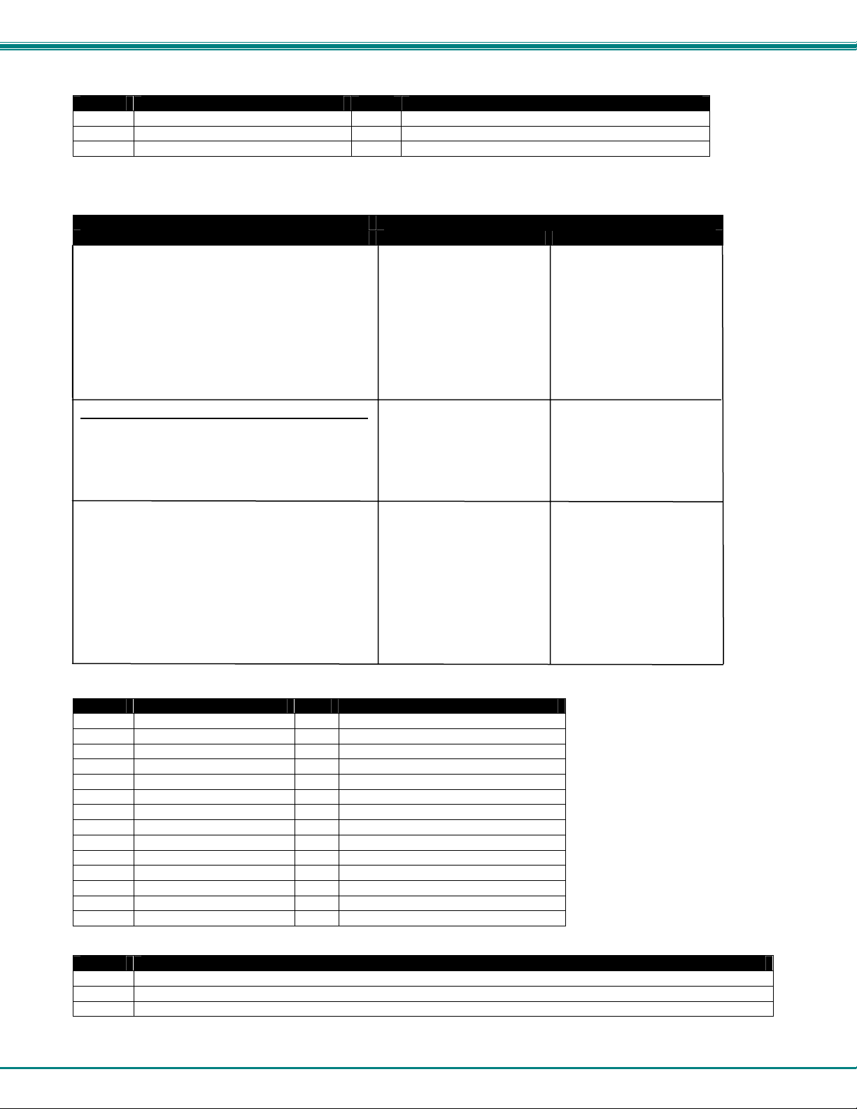
NTI RACKMUX RACKMOUNT ANSI TERMINAL DRAWER
Supported VT100, VT220 and Console ANSI Commands (Cont'd)
final
Final character
final
A Designating UK ANSI character set < Designating DEC supplemental(VT 220 only)
B Designating ASCII character set DSCS Designating Down-line loadable character set
0 Designating DEC special graphics
* DSCS can consist of zero, one or two intermediate character and a final character. Intermediate characters are
in the range of 2/0 to 2/15. Final characters are in the range of 3/0 to 7/14
Command
FUNCTION VT100, VT220 Console ANSI
Load G0 character set into GL CTRL O Same
Load G1 character set into GL CTRL N Same
Load G1 character set into GR ESC ~ Same
Load G2 character set into GL ESC n Same
Load G2 character set into GR ESC } Same
Load G3 character set into GL ESC o Same
Load G3 character set into GR ESC | Same
Shift G2 character set into GL for one character only ESC N Same
Shift G3 character set into GL for one character only ESC O Same
Controlling Character, Field, and Line Attributes
Define character attributes
CSI Ps m (see table below) Same
*3
Select Graphic Rendition
(Console ANSI mode only) CSI ps m (see table below)
Set bold background bit ESC[ =PnE same
Pn = 0: set bit 7 of attribute byte as B/G intensity
1: set bit 7 of attribute byte as B/G blink
Set normal foreground color ESC[ = Psn F (see table, same
Set normal background color ESC[ = Psn G next page) same
Set reverse foreground color ESC[ = Psn H same
Set reverse background color ESC[ = Psn I same
Set graphic foreground color ESC[ = Psn J same
Set graphic background color ESC[ = Psn K same
Set border color ESC[ = Psn A same
Values for “ Ps” (above)
Ps
Character Attribute
Ps
Character Attribute
0 Normal (all attributes off) 33 Brown character (Bold on = Yellow)
1 Bold (blank off) 34 Blue character
4 Underline 35 Mage nta character
5 Blink 36 Cyan character
7 Reverse 37 White character
8 Blank (bold off) 40 Black background
22 Normal intensity 41 Red background
24 Underline off 42 Green background
25 Blink off 43 Brown background (Bold on = Yellow)
27 Reverse off 44 Blue background
28 Blank off 45 Magenta background
30 Black character 46 Cyan background
31 Red character 47 White background
32 Green character
Values for “ps” (above)
ps
Function
10 Select Primary Font
11 Select First Altemate Font. Allows ASCII characters less than 32 to be displayed as ROM character.
12 Select Second Alternate Font. Toggles hig h bit of extended ASCII code be fore displaying as ROM character.
Final character
31
Page 36
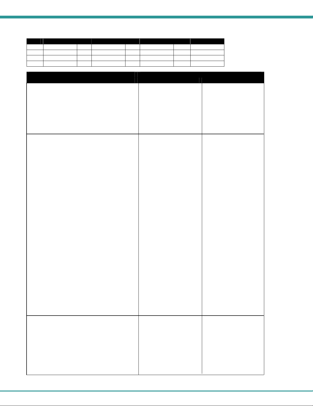
NTI RACKMUX RACKMOUNT ANSI TERMINAL DRAWER
Supported VT100, VT220 and Console ANSI Commands (Cont'd)
Values for “Psn” in table on page 56
Psn
Color
0 Black 4 Red 8 Gray 12 Lt. Red
1 Blue 5 Magenta 9 Lt.Blue 13 Lt. Magenta
2 Green 6 Brown 10 Lt. Green 14 Yellow
3 Cyan 7 White 11 Lt. Cyan 15 Lt. White
Command
FUNCTION VT100, VT220 Console ANSI
Access alternate graphic set CSI Png
Define erasable character CSI 0 "q or CSI 2 "q Same
Define non-erasable character CSI 1 "q Same
Define top half of double-high, double-wide line ESC # 3 Same
Define bottom half of double-high, double-wide line ESC # 4 Same
Define single-high, single-wide line ESC # 5 Same
Define single-high, double-wide line ESC # 6 Same
Define top half of double-high, single-wide line ESC # : Same
Define bottom half of double-high, single-wide line ESC # ; Same
Controlling the Cursor
Display cursor CSI ?25 h Same
Cursor off CSI ?25 l Same
Cursor steady (nonblinking) CSI 33 h Same
Cursor blinking CSI 33 l Same
Underline cursor on CSI 34 h Same
Block cursor on CSI 34 l Same
Cursor keys send application-dependent codes CSI ?1 h Same
Cursor keys send cursor movement codes CSI ?1 l Same
Move cursor to n column CSI n G or CSI n ` Same
Move cursor up n lines CSI n A Same
Move cursor down n lines CSI n B or CSI n e Same
Move cursor right n columns CSI n C or CSI n a Same
Move cursor left n columns CSI n D Same
Move cursor down cursor n line to column 1 CSI n E Same
Move cursor up n lines to column 1 CSI n F Same
Move cursor to line n CSI n d Same
Move cursor to line n1, column n2 CSI n1; n2 H Same
Move cursor down one line in current column, IND Same
scroll up if at bottom line or ESC D Same
Move cursor down one line in current column, CTRL J Same
execute CR if linefeed mode is on or CTRL K or CTRL L Same
Move cursor up one line in current column, RI Same
scroll down if at top line or ESC M Same
Move cursor down one line to column 1 NEL or ESC E Same
Save display attributes, cursor position, character ESC 7 Same
sets,wrap flag and origin mode status or CSI s Same
Restore last saved display attributes, cursor position, ESC 8 Same
character set, wrap flag, and origin mode status or CSI u Same
Backspace cursor CTRL H Same
Move cursor to next tab stop CTRL I Same
Move cursor to column 1 of current line CTRL M Same
Editing Functions
Erase from cursor to end of display CSI 0 J Same
Erase from start of display to cursor CSI 1 J Same
Erase entire display CSI 2 J Same
Erase from cursor to end of line CSI 0 K Same
Erase from start of line to cursor CSI 1 K Same
Erase entire line CSI 2 K Same
Erase erasable characters from cursor to CSI ?0 J Same
end of display
Psn
Color
Psn
Color
Psn
Color
or CSI n1; n2 f Same
32
Page 37
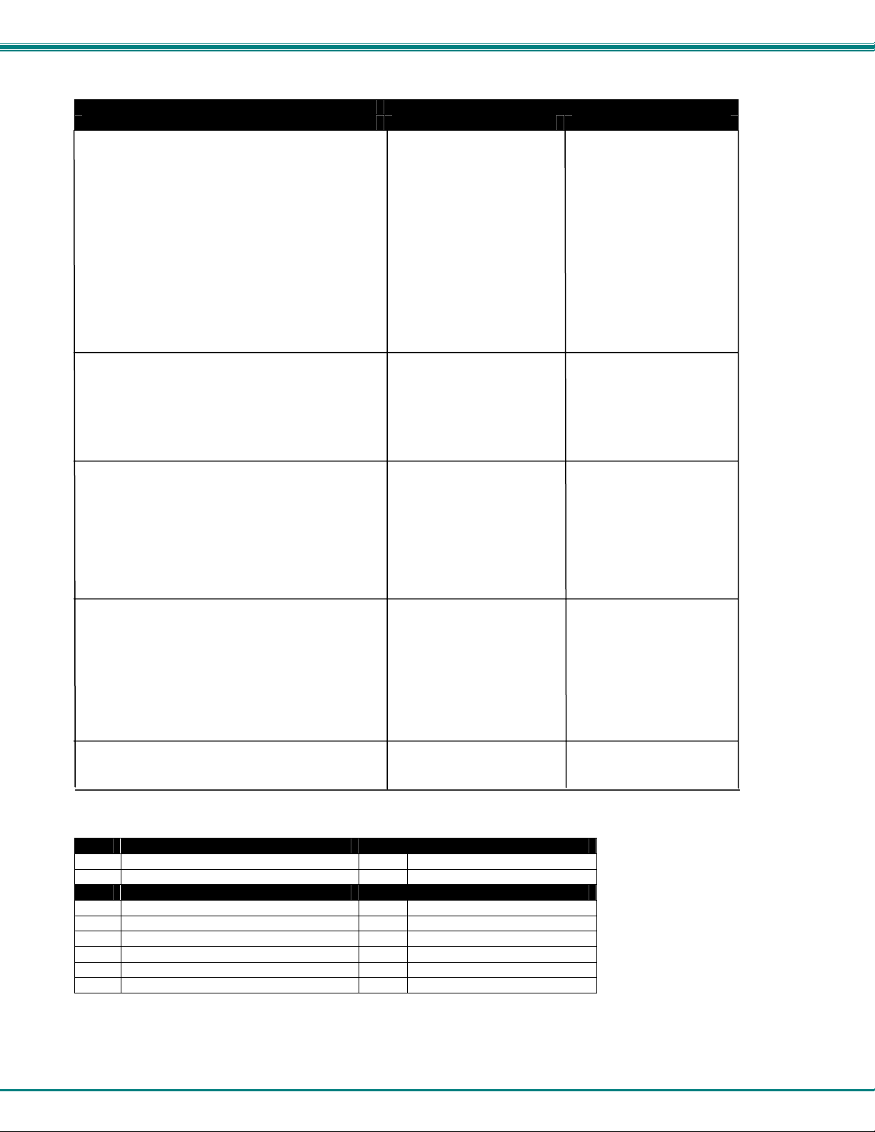
NTI RACKMUX RACKMOUNT ANSI TERMINAL DRAWER
Supported VT100, VT220 and Console ANSI Commands (Cont'd)
Command
FUNCTION VT100, VT220 Console ANSI
Editing Functions (Cont'd)
Erase erasable characters from start of display CSI ?1 J Same
to cursor
Erase erasable characters in entire display CSI ?2 J Same
Erase erasable characters from cursor to end of line CSI ?0 K Same
Erase erasable characters from start of line CSI ?1 K Same
to cursor
Erase erasable characters from entire line CSI ?2 K Same
Erase n characters beginning at cursor CSI n X Same
Insert n blank characters beginning at cursor CSI n @ Same
Insert n blank lines beginning at cursor line CSI n L Same
Delete n line beginning at cursor line CSI n M Same
Delete n characters beginning at cursor CSI n P Same
Controlling Margins
Set top/bottom margins of scrolling CSI t;b r Same
t: Top line number
b: Bottom line number (optional; if omitted, treated
as bottom screen line)
Controlling Tabs
Clear tab stop at cursor CSI 0 g or CSI 2 W CSI 2W
Clear all tab stops CSI 3 g or CSI 5 W CSI 5W
Set tab stop at cursor CSI 0 W or ESC H Same
Set tab stop every 8th column CSI ?5 W Same
Move forward n tab stops CSI n I Same
Move backward n tab stops CSI n Z Same
Move cursor to next tab stop CTRL I Same
Controlling Scrolling
Smooth scrolling on CSI ?4 h Same
Jump scrolling on CSI ?4 l Same
Set 0 lps smooth scrolling speed CSI 0 z
Set 1 lps smooth scrolling speed CSI 1 z
Set 2 lps smooth scrolling speed CSI 2 z
Set 4 lps smooth scrolling speed CSI 3 z
Set 8 lps smooth scrolling speed CSI 4 z
Program function keys DCS c;kl | ESC Q Fn
(see tables below an on next page for values) kc/hc ST "string"
Program function key values in VT100 mode:
c
Clear
kl
0 Clear all key definitions 0 Lock key definitions
1 Clear keys only as they are redefined 1 Don't lock key definitions
kc
Shifted function key
kc
12 F1 18 F7
13 F2 19 F8
14 F3 20 F9
15 F4 21 F10
16 F5 23 F11
17 F6 24 F12
Key Lock
Shifted function key
33
Page 38
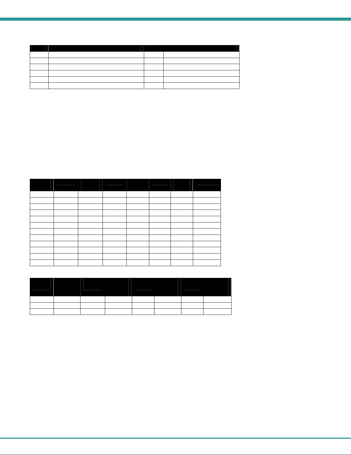
NTI RACKMUX RACKMOUNT ANSI TERMINAL DRAWER
Supported VT100, VT220 and Console ANSI Commands, Cont'd
kc
6 F1 38 F7
7 F2 39 F8
8 F3 40 F9
9 F4 41 F10
10 F5 43 F11
37 F6 44 F12
hc Hexadecimal representation of character string assigned to the function key.
Note: Multiple function key definitions can be programmed by entering the <kc>/<hc> parameters for each, separated by
semicolons (;).
Program function key values (from previous page) in Console ANSI mode:
Unshifted function key
kc
Unshifted function key
Redefine keys with string
Function: Define Specific Programmable Function key or Numeric keypad with String.
Format: ESC Q Fn “ string “
Values of Fn for Programmable Function keys
Fn
Value
0 F1 < S_F1 H C_F1 T C_S_F1
1 F2 = S_F2 I C_F2 U C_S_F2
2 F3 > S_F3 J C_F3 V C_S_F3
3 F4 ? S_F4 K C_F4 W C_S_F4
4 F5 @ S_F5 L C_F5 X C_S_F5
5 F6 A S_F6 M C_F6 Y C_S_F6
6 F7 B S_F7 N C_F7 Z C_S_F7
7 F8 C S_F8 O C_F8 [ C_S_F8
8 F9 D S_F9 P C_F9 \ C_S_F9
9 F10 E S_F10 Q C_F10 ] C_S_F10
: F11 F S_F11 R C_F11 ^ C_S_F11
; F12 G S_F12 S C_F12 _ C_S_F12
Values of Fn for Numeric Keypad keys
Fn
Value
- 7 c - f 6 i 2
a 8 d 4 g + j 3
b 9 e 5 h 1 k 0
Notes:
1. The string should not include the delimiter, or unexpected conditions maybe occur.
2. The defined contents of F1 ~F12 will be transmitted out by keying F1~F12.
The defined contents of S_F1~S_F12 will be transmitted out by multi-keying the Shift and Function key.
The defined contents of C_F1~C_F12 will be transmitted out by multi-keying the Ctrl and Function key.
The defined contents of C_S_F1~C_S_F12 will be transmitted out by multi-keying the Ctrl, Shift and Function key.
Example: Define Function Key F1 to the character ABC123: ESC Q 0"ABC123"
F Key
Numeric
Keypad
Key
Fn
Value
Fn
Value
F Key
Numeric
Keypad
Key
Fn
Value
Fn
Value
F Key
Numeric
Keypad
Key
Fn
Value
Fn
Value
34
F Key
Numeric
Keypad
Key
Page 39

NTI RACKMUX RACKMOUNT ANSI TERMINAL DRAWER
Supported VT100, VT220 and Console ANSI Commands (Cont'd)
Command
FUNCTION VT100, VT220 Console ANSI
Auxiliary Keypad Modes
Auxiliary keypad numeric mode on ESC > Same
Auxiliary keypad application mode on ESC = Same
Transmission/Printer Control
Transmit through cursor position CSI 16 h Same
Transmit to end of line or end of display CSI 16 l Same
Send form feed after print screen operation CSI ?18 h Same
No form feed sent after print screen operation CSI ?18 l Same
Print full screen CSI ?19 h Same
Print scrolling region CSI ?19 l Same
Print screen CSI 0 i or CSI i Same
Send screen CSI 2 i Same
Transparent print mode off CSI 4 i Same
Transparent print mode on CSI 5 i Same
PR port receive mode off CSI 6 i Same
PR port receive mode on CSI 7 i Same
Select parallel printer CSI 8 i Same
Select serial printer CSI 9 i Same
Print line CSI ?1 i Same
Send line CSI ?3 i Same
Copy print mode off CSI ?4 i Same
Copy print mode on CSI ?5 i Same
Transmit form feed after send screen operation CSI 1 | Same
No form feed after send screen operation CSI 0 | Same
Send characters at cursor ESC 5 Same
Send answerback message CTRL E Same
Suspend transmission CTRL S Same
Resume transmission CTRL Q Same
More Terminal Control Commands
Display screen adjustment pattern ESC # 8 Same
Sound bell, if enabled BEL (CTRL G) Same
Abort escape sequence; no character displayed*3 CAN (CTRL X) Same
Abort escape sequence; display reverse question SUB (CTRL Z) Same
mark^
Initiate escape sequence ESC (CTRL [] Same
Next Page CSI U Same
Preceding Page CSI V Same
Terminal Resets
Soft terminal reset CSI ! p Same
Hard terminal reset ESC c Same
Terminal Status Reports
Request primary attributes report CSI 0 c or ESC Z Same
Request secondary attributes report CSI > 0 c Same
Respond with current revision CSI > 1; 20; 0c Same
Request terminal status report CSI 5 n Same
Respond terminal functioning and ready CSI 0 n Same
Request cursor position report CSI 6 n Same
Respond cursor at line l, column c CSI l; c R Same
Request printer status report CSI ?15 n Same
Respond printer ready CSI ?10 n Same
Respond printer not ready CSI ?11 n Same
Respond printer not connected CSI ?13 n Same
Request function key status report CSI ?25 n Same
Respond key definitions not locked CSI ?20 n Same
Respond key definitions locked CSI ?21 n Same
35
Page 40
NTI RACKMUX RACKMOUNT ANSI TERMINAL DRAWER
Supported VT100, VT220 and Console ANSI Commands, Cont'd
Command
FUNCTION VT100, VT220 Console ANSI
Request keyboard status report CSI ? 26 n Same
Respond with keyboard language CSI ? 27; Ps n Same
(see table below for values of “Ps”)
Values of Ps (above)
Ps
1 U.S. 6 Spanish
2 U.K. 7 Swedish
3 Danish 8 Norwegian
4 German 9 Italian
5 French
*1. More than one mode, but less than 17, may be set with one sequence. Enter multiple numeric parameters separated
by semicolons (;). However you cannot combine sequences containing "?" with those that don't contain "?", nor can
you combine sequences ending with "h" with those ending with "l".
*2. To toggle monitor mode from the keyboard, press CTRL SHIFT 1 (use the 1 on the numeric keypad).
*3. In VT52 or VT100 modes, displays checkerboard character.
Keyboard Language
Ps
Keyboard Language
6.2 VT52 Command Guide
Table 11- VT52 Mode Escape Sequences
Command VT52
Move cursor up one line ESC A
Move cursor down one line ESC B
Move cursor right one column ESC C
Move cursor left one column ESC D
Move cursor to home position ESC H
Move cursor up one line with scroll ESC I
Move cursor to line line, column col ESC Y line col
Select graphics character set ESC F
Select U.S. ASCII character set ESC G
Erase from cursor to end of display ESC J
Erase from cursor to end of line ESC K
Print cursor line ESC V
Print display ESC ]
Transparent print mode on ESC W
Transparent print mode off ESC X
Copy print mode on ESC ^
Copy print mode off ESC _
Keypad application mode on ESC =
Keypad application mode off ESC >
Enter VT100 mode ESC <
Identify terminal ESC Z
36
Page 41

NTI RACKMUX RACKMOUNT ANSI TERMINAL DRAWER
7. USING PRINTER SERVER IN ETHERNET TERMINAL
Introduction
There are two ways to send the print jobs to Ethernet Terminal for printing: 1) through LPD protocol, and 2) through TFTP
protocol.
• The LPD method is more suitable for printing environments with a large number of users because the LPD
protocol has a queue process so print jobs will be kept in the print queues in the CPU.
• TFTP does not implement the print queue concept; if the printer port is not ready for accepting new print jobs, TFTP
will be terminated. Consequently, the user must send the print job again. As a result, the TFTP protocol is suitable for
printing small jobs, in an environment with a small number of users, or for testing purposes.
LPD is a built-in printing protocol in the BSD type of UNIX and is also available in most other UNIX systems. With LPD, users do
not need to install additional software to the CPU to print the jobs. Most implementations of the LPD protocol send out the data file
before the control file. However, since Ethernet Terminal must print the data file immediately upon receiving it, the print option
specified in the control file cannot take affect.
To install the printer server function of Ethernet Terminal, the first step is Basic Setup. Whichever printing protocol will be used, it
is necessary to follow "Basic Setup" first (below). If LPD will be used to print jobs, go through the "Setup for LPD" procedures
(below). If TFTP will be used, go through the "Setup for TFTP" procedures (page 37).
7.1 Basic Setup
Because the TCP/IP world uses IP addressing to communicate with each other, the purpose of Basic Setup is to assign an
IP address to the Ethernet Terminal.
For the purpose of this explanation, assume the following:
(1) Login to the UNIX CPU as root
(2) The Ethernet terminal is on the same network segment that the CPU resides.
Step 1. Add the Print Server to /etc/hosts
Create a new entry in the /etc/hosts file on all UNIX CPUs that are slated to work with Ethernet Terminal.
To create a new entry, add the following line:
IP_Address PS_NAME # comment
where: IP_Address is an IP address.
PS_NAME is a CPU name of a print server.
The statement after # is the comment for the new entry.
e.g. 90.3.2.2 ETPS1 # Ethernet Terminal
This example assigns the name ETPS1 to the Ethernet Terminal with IP address 90.3.2.2.
NOTE: The IP address is defined in the setup screen of Ethernet Terminal, as a Local IP address. Use the same one.
Step 2. Check to see if the above steps are completed
To verify if the IP address of print Server function is installed successfully, issue the following "ping" command:
ping PS_NAME [Enter]
e.g. ping ETPS1 [Enter]
7.2 Setup for LPD
Follow those steps from step 1 to step 2 described in Basic Setup. The following steps are dependent on the operating system.
Please refer to the UNIX administration guide. The following illustrated steps are under BSD system.
Step 3. Create a spooling directory
Use mkdir command to create a directory for spooling.
e.g. mkdir/usr/spool/ETPS1
37
Page 42

NTI RACKMUX RACKMOUNT ANSI TERMINAL DRAWER
Step 4. Make the directory available to LPD main process
Basically, the method has the following three procedures:
1) Assign the spooling daemon as the owner of this directory.
2) Allow the spooling daemon to be able to read from or write to the directory.
3) Enable the group of LPD main processes to be able to read from or write to the directory.
e.g. If it works on a BSD UNIX host and makes the directory /usr/ spool/ETPS1 (created in step 3) available, then follow
these three procedures:
chown daemon /usr/spool/ETPS1
chmod 775 /usr/spool/ETPS1
chgrp daemon /usr/spool/ETPS1
Step 5. Add a remote printer
To add a remote printer, insert a block similar to the following in the /etc/printcap file.
Printer_name|Remote Printer on Ethernet Terminal:\
:lp=:\
:rm=PS_NAME:\
:rp=Logic_Printer_name:\
:sd=<full path of spooler directory name>:\
e.g. If Ethernet Terminal works on a BSD UNIX host, then insert the following block into /etc/printcap file.
ETPS1|Remote Printer on Ethernet Terminal:\
:lp=:\
:rm=ETPS1:\
:rp=L1:\
:sd=/usr/spool/ETPS1:\
Step 6. Start CPU's print mechanism for BSD version UNIX system
Typing: lpc start printer_name [Enter]
e.g. lpc start ETPS1 [Enter]
Now the Ethernet Terminal is configured to accept LPD printing..
7.3 LPD printing
LPD protocol is built-in to most of the UNIX system. However, detailed implementation of LPD differs among UNIX systems.
Please refer to the UNIX administration guide for reference. The following illustrated printing command is under BSD system or
System V version.
For BSD system: lpr -P <printer_name><filename>
For System V version: lp -d <printer_name><filename>
This command is to print selected file to the selected printer.
e.g. lpr -PETPS1 /etc/hosts (BSD version) or lp -dETPS1 /etc/hosts (System V version)
This example is to print the /etc/hosts file to the Ethernet Terminal printer.
38
Page 43

NTI RACKMUX RACKMOUNT ANSI TERMINAL DRAWER
7.4 Setup for TFTP
When working on the BSD UNIX system, run the setup procedure under Setup for LPD on page 34. Otherwis e run the Setup for
LPD omitting step 6.
7.5 TFTP Printing
Before using TFTP printing, the Ethernet Terminal needs to be installed completely by Setup for TFTP on page 34. TFTP Printing
lets the user send print jobs to the printers directory. There are no spooling mechanisms involved. Consequently, if that printer is
not ready, the TFTP process will be terminated immediately without sending print jobs to printers. The user must make sure the
printer is ready to print before issuing the TFTP command to have a successful result.
Log into the Ethernet Terminal with this command:
tftp <PS_NAME>
and then type:
put <file Name> Ln
where Ln is a logic printer for L1 to L8
e.g. tftp ETPS1
tftp > put /etc/hosts L1
This example prints the /etc/hosts file to the logic printer 1 of Ethernet Terminal Printer ETPS1.
39
Page 44

NTI RACKMUX RACKMOUNT ANSI TERMINAL DRAWER
8. ON-SCREEN DISPLAY (OSD)
8.1 Standard Controls
The RACKMUX LCD has 5 standard control buttons and a power LED. The 5 standard control buttons operate as follows:
• The Power button turns the RACKMUX LCD and backlight ON and OFF as desired.
• The Power LED located immediately below the Power button is a dual color
LED. It will illuminate with a green color when the RACKMUX is powered
ON and working properly. It will illuminate with a red color if the RACKMUX
is powered ON but there is no input signal detected. The LED will
illuminate red only momentarily just before turning OFF.
• The Menu button is used to bring up the OSD menu where the various
settings of the LCD display can be adjusted. Once the OSD screen is
displayed, the Menu button is used to make selections within the menus.
See "OSD Control Menu " (below) for more on LCD display settings.
• The Up and Down Arrow buttons are used to navigate through the
menus. Move the cursor up or down as desired to highlight an item for
selection. Once an item is highlighted, pressing the Menu button will
select it.
Figure 7- OSD Controls
• The Select button is used to make selections within the OSD menus when
the OSD menu is ON. When the OSD menu is OFF, the Select button will
act as an Auto Adju s t button to keep the user from having to use the menus
to adjust the quality of the image on the monitor.
Power
ON/OFF
Power LED
Menu
Up Arrow
Down Arrow
Select/
Auto Adjust
Controls for the
OSD Menus
8.2 OSD Control Menu
The OSD (On Screen Display) Menu enables the user to select the desired characteristics of the LCD di splay. T o activate the
OSD Menu, press the Menu button (above). To turn the Menu back OFF, either select "EXIT" from the main menu or just wait
10-60 seconds and it will automatically be cleared from the screen.
8.2.1 OSD Main Menu
Selection Purpose Range
Brightness/Contrast Increase/decrease panel brightness/contrast level 1-100
Color R,G,B color temperature control 1-100
Position
Setup
Exit Exit from the OSD control menu
• Auto Adjust
• Video Image horizontal and vertical position control
• Clock setting
• Phase control
• Control OSD Image position on screen
• Set time OSD will stay on screen before auto shutoff
• Select the language of the OSD menu
40
1-100
-10 to 60 seconds
Several languages (see page 40)
Page 45

NTI RACKMUX RACKMOUNT ANSI TERMINAL DRAWER
8.2.2 Brightness/Contrast Menu
Selecting the Brightness/Contrast menu will bring up a screen in which the user can adjust the brightness and contrast levels of
the LCD display. With either the BRIGHTNESS or CONTRAST sections highlighted, (use the Up or Down arrow to move
between them), press the Select button to choose the option to adjust. Then use the Up or Down Arrow to adjust the setting.
Select EXIT when finished to return to the Main Menu.
8.2.3 Color Menu
Selecting the Color menu will bring up a screen in which the user can adjust the Red, Green, and Blue color levels (values from 1-
100) of the LCD display. With the RED, GREEN, or BLUE sections highlighted, (use the Up or Down arrow to move between
them), press the Select button to choose the option to adjust. Then use the Up or Down Arrow to adjust the setting.
Select EXIT when finished to return to the Main Menu.
8.2.4 Position Menu
Selecting the Position menu will bring up a screen in which the user can select AUTO ADJUST to automatically adjust the
horizontal and vertical position of the displayed image on the monitor, as well as adjust the clock and phase settings if they are not
correct. The user can also individually adjust these settings if so desired. With any of the sections highlighted, (use the Up or
Down arrow to move between them), press the Select button to choose the option to adjust. Then use the Up or Down Arrow
to adjust the setting as needed. Select EXIT when finished to return to the Main Menu.
.
41
Page 46

NTI RACKMUX RACKMOUNT ANSI TERMINAL DRAWER
8.2.5 Setup Menu
Selecting the Setup menu will bring up a screen in which the user can adjust
OSD POSITION-the position of the OSD menus on the LCD display
OSD TIME-the length of time the user can be idle before the OSD menu automatically exits (adjustable from 10
to 60 seconds)
LANGUAGE-the language that the OSD menus will be presented in
With the item highlighted, (use the Up or Down arrow to move between them), press the Select button to choose the option to
adjust. Then use the Up or Down Arrow to adjust the setting as needed. Select EXIT when finished to return to the Main
Menu.
OSD Image can be moved
to different points on the
display
42
Page 47

NTI RACKMUX RACKMOUNT ANSI TERMINAL DRAWER
9. KEYBOARD FUNCTIONS
The keyboard on the RACKMUX has a standard condensed Windows format. To reduce the keyboard size, some keys have
been assigned multiple functions, accessible via the "Fn" key. This section will describe which keys have multiple functions and
how to enable them.
9.1 Function Key Operation
The Function (“Fn”) key provides special functions on the RACKMUX keyboard, including:
enabling otherwise standard keyboard keys to be used as the keys of a numeric keypad
enabling multi-function keys to change operation
To turn ON (lock) the Function key, press the “Fn” key twice quickly (double-click). The “Fn” LED will illuminate.
To turn OFF (unlock) the Function key, press the “Fn” key twice quickly again. The “Fn” LED will turn OFF.
Note: The "Fn" key will also operate similar to the shift key (with only momentary effect). Press and hold the "Fn" key
prior to pressing the special function key. The "Fn" key will remain active as long as it is depressed.
Esc
~
`
Tab
CapsLock
Fn
F1
!
1
Q
Shift
Ctrl
F3
F4
@
2
#
3
$
4
WE R
F5
F6
F7
%
5
^
6
T
F8
F9
&
7
789
*
8
YU I OP
ASDF GH JKL
123
ZXCVB
Alt
N
F2
"Fn" Key to enable ad diti onal key functions
Figure 8- US (English) Keyboard Layout
On= CapsLock
is locked
1
A
On= NumLock
is locked
On= Scroll Loc k
is locked
Figure 9- Keyboard LED Indications
(
9
F11 F12
)
0
654
<
,
F10
M
Alt
On= Function
Key feature
is ON
Fn
Num Lk
:
;
+
>
.
.
Enter
{
[
?
/
/0
Ctrl
Insert Delete
Prt Sc
+
=
"
'
*
}
]
Shift
Home
Sys Rq
Backspace
Enter
Pg Up
Pause
BreakScr Lk
\
EndPg Dn
43
Page 48

NTI RACKMUX RACKMOUNT ANSI TERMINAL DRAWER
9.2 Number Pad
The functionality of a Number Pad on a standard Windows keyboard has been incorporated into this keyboard. To
substitute the keys of the Number Pad
Table 12- Number Pad Keys
To substitute the keys of the Number Pad:
1. Press the "NumLock" key. The NumLock LED ( ) will illuminate.
2. Press the "Fn" key twice quickly (double-click). The "Fn" LED will illuminate.
To turn OFF Number Pad functions:
1. Press the "Fn" key twice quickly (double-click). The "Fn" LED will turn OFF.
2. Press the "NumLock" key. The NumLock LED ( ) will turn OFF.
Note: For only momentary function of the “Fn” key, press and hold the “Fn” key (similar to the “Shift” key).
Upon release the Fn feature will be OFF.
With the “Fn” and “NumLock” LEDs illuminated, pressing some standard keys will result in displaying characters as
indicated in the chart below. (See also Fig. 10, page 44)
Standard Key Displayed w hen Nu mLock is
ON
j “ 1 ” End
k “ 2 ” Down Arrow
l “ 3 ” Page Down
u “ 4 ” Left Arrow
i “ 5 ” ---
o “ 6 ” Right Arrow
7 “ 7 ” Home
8 “ 8 ” Up Arrow
9 “ 9 ” Page Up
m “ 0 ” Insert
.
(period)
“ . ”
(period)
/
(forward slash)
;
(semicolon)
’
(apostrophe)
-
(hyphen)
[
(left bracket)
&
7
789
*
8
(
9
UIO
654
JKL
123
M
Figure 10- Keys of the Number Pad
1
1
“ / ”
(forward slash)
“ + ”
(plus sign)
“ * ”
(asterisk)
-
(minus sign)
ENTER
NUMLCK
SCR LCK
:
;
+
>
.
.
Function when NumLock is
OFF
Delete
{
[
Enter
"
'
*
?
/
/0
44
Page 49
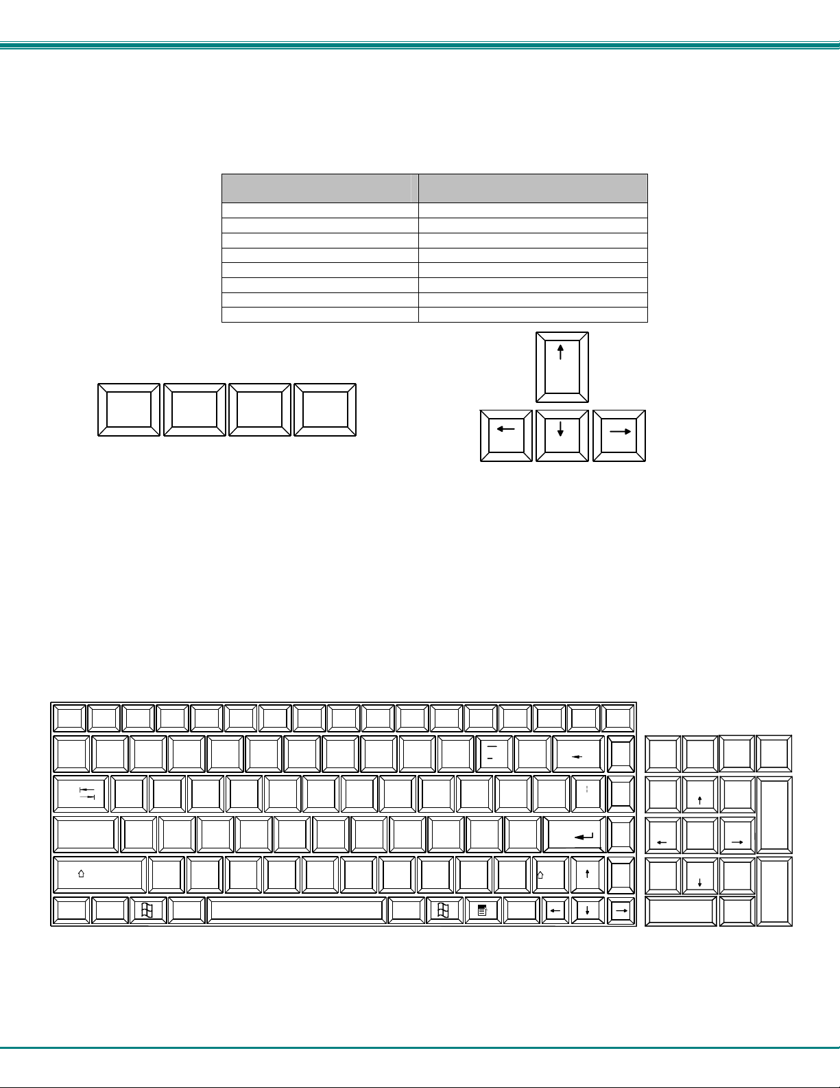
NTI RACKMUX RACKMOUNT ANSI TERMINAL DRAWER
9.3 Other Uses of the Function Key
The Function ("Fn") key (page 43) will enable other standard keyboard features in addition to the Number Pad keys (page 44) .
Key Function when Fn key is
not locked ("Fn" LED is OFF)
Numlck (Number lock) Scr Lck (Scroll Lock)
Insert Prt Sc (Print Screen)
Delete Sys Rq (System Requirements)
Pause Break
Up Arrow Page Up
Down Arrow Page Down
Left Arrow Home
Right Arrow End
Num Lk
Scr Lk
Insert Delete
Prt Sc
Sys Rq
Pause
Break
Figure 11- Additional multi-function keys
Note: The "Fn" key will also operate similar to the shift key (with only momentary effect).
Key Function when Fn key is
Locked ("Fn" LED is ON)
Pg Up
Home
EndPg Dn
9.4 Numeric Keypad Option
Models with the Numeric Keypad option (-N) (i.e. RACKMUX-T15-N) have a standard Windows keyboard with 17-key numeric
keypad.
Note: The “Fn” key is not an active key on this keyboard.
Scroll
Esc
~
`
Tab
Caps Lock
Fn
Shift
F2
F1
!
1
Q
F3
F4
@
#
2
$
3
4
WE R
F6
F5
%
5
F7
F8
F9
&
^
7
6
T
YU I OP
*
8
ASDF GHJKL
Ctrl
ZXCVB
Alt
M
N
F11 F12
F10
)
(
0
9
<
,
Alt
PrtSc
SysRq
{
[
:
"
;
'
?
>
.
/
Insert
Figure 12- U.S. (English) Keyboard with numeric keypad
+
=
Lock
}
]
Shift
Backspace
Enter
Pause
Break
Delete
Home
Page
\
Up
Page
Down
End
Num
Lock
Home Pg Up
End
0
Ins
/
789
456
123
*
PgDn
.
Del
-
+
Enter
45
Page 50
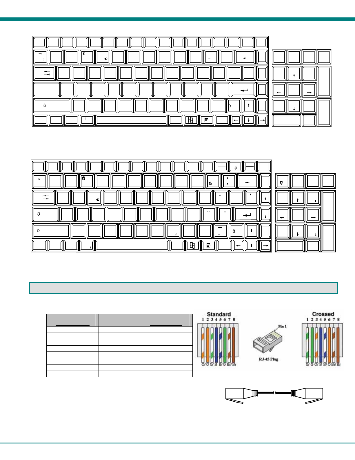
NTI RACKMUX RACKMOUNT ANSI TERMINAL DRAWER
F2
F1
Esc
!
1
`
F3
F4
"
2
$
3
4
F6
F5
%
5
F7
F8
F9
&
^
6
*
8
7
F10
(
9
F11 F12
)
0
Tab
WE R
Q
T
YU I OP
Caps Lock
ASDFGH JKL
Shift
Ctrl
Fn
ZXCVB
Alt
\
N
<
,
M
AltGr
Figure 13- U.K. (English) keyboard with numeric keypad
F2
F1
Esc
!
1
^
F3
"
2
2
3
3
F4
$
4
F5 F6 F7
%
&
6
5
/
7 {
F8
F9 F10
(
8 [
)
9 ]
F11 F12
=
0 }
Tab
Q
WE R
@
T
ZU I OP
ASDFGH JK L
Strg
Fn
YXCVB
>
Alt
<
N
;
,
M
u
AltGr
Figure 14- German keyboard with numeric keypad
PrtSc
SysRq
{
[
:
@
;
'
?
>
.
/
Insert
Druck
S-Abf
?
\
U
O
:
.
Einfg
Pause
Scroll
Lock
+
Backspace
=
}
]
Enter
Shift
Rollen
*
+ ~
A
Break
~
#
Pause
Untbr
Delete
End
Entf
Pos1
Ende
Bild
Bild
Num
Lock
Home
End
0
Ins
Home
Page
Up
Page
Down
'
#
/
*
789
456
123
Num
789
Pos1
456
123
Ende
0
PgUp
PgDn
.
Del
/
*
Bild
Bild
.
Entf Einfg
-
+
Enter
-
+
Enter
10. CPU-TO-RACKMUX ETHERNET CROSSOVER CABLE
In order to make a direct connection between a CPU and the ETHERNET connector of the RACKMUX, a crossover cable must be
used. The cable is made with CAT5 cable terminated with RJ45 connectors and wired according to the chart below.
Pin assignment at
Standard End
1 White/Orange 3
2 Orange 6
3 White/Green 1
4 Blue 4
5 White/Blue 5
6 Green 2
7 White/Brown 7
8 Brown 8
Wire Color Pin assignment at
Crossed End
46
Standard
End
Crossed
End
Crossover Cable
Page 51
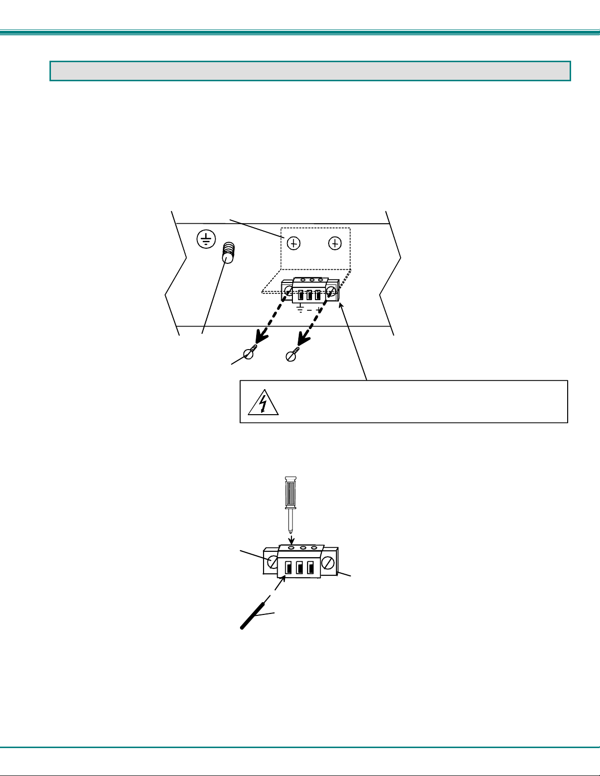
NTI RACKMUX RACKMOUNT ANSI TERMINAL DRAWER
11. DC POWER OPTION
If the RACKMUX has been ordered with the DC Power option (“48V” at the end of the model number), a 3-terminal block has
been provided for connection to a 36-72VDC 2A power source. The terminal block can be easily removed from under the
protective bracket to make connections. Proper connections are indicated.
Note: Be sure to properly secure the terminal block to the RACKMUX after wire insertion.
An earth ground terminal has been provided for optional use.
Figure 15- RACKMUX with DC Power option
Figure 16- Apply wires to terminal block
Earth ground connection
protective bracket
Remove screws to remove
terminal block
Remove screws
to remove
terminal block
REAR VIEW OF RACKMUX-T1 548V
36-72VDC
CAUTION: RISK OF ELECTRIC SHOCK
36-72VDC PRESENT ON DC POWER INPUT
Phillips
screwdriver
terminal block
Power supply
ground
47
Page 52
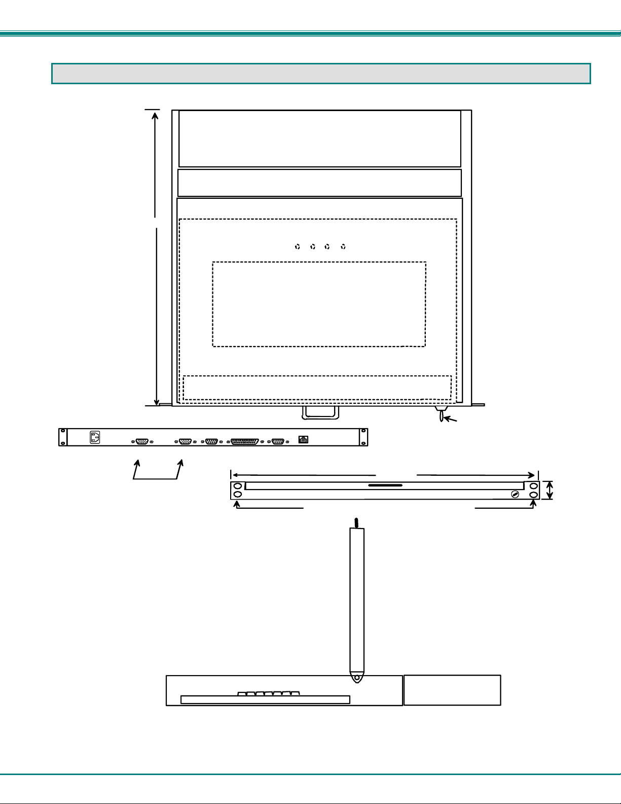
NTI RACKMUX RACKMOUNT ANSI TERMINAL DRAWER
DIMENSIONAL DRAWINGS
Overhead View of RACKMUX-T15
21 .9 IN .
15" LCD Display
IEC CONNECTOR
VGA
(OUT) (IN)
CONNECT PORTS WITH
VEXT-1,5-M M (SUPPLIE D)
MONITOR
Keyboard
SERIAL 2 PARALLEL SERIAL 1
Rear View of RACKMU X-T15
Wristpad
10BaseT
19.00 IN.
Front View of RACKMU X-T15
Slotted holes for securing terminal drawer to rack
Lock
1.75 IN.
Side View of RACKMUX-T15
48
Page 53

NTI RACKMUX RACKMOUNT ANSI TERMINAL DRAWER
FREQUENTLY ASKED QUESTIONS
Questions and Answers
Q. What servers can the monitor be used with?
A. All Sun and headless servers to date include at least one serial RS232 port that is used as a console port when
no directly connected keyboard is present. The Ethernet console connection should only be used with servers that
include an Ethernet RSC (Remote System Control) port. Both RS232 serial and Ethernet telnet connections
cannot be active at the same time.
Q. How do I connect the terminal to a single server using a RS232 serial connection?
A. An RS232 cable is required for connection to a server with either a male DB25 or DB9 serial port. When
connecting to a Sun server with a RJ45 console port, use the RJ45 cable and RJ45 to DB25 adapter which are
included with the server. If the RJ45 to DB25M adapter and RJ45 cable are not available, contact NTI to order
DB25M-RJ45F-T (adapter) and a Cat5 Patch cable (RJ45) of the desired length.
Q. How do I connect the terminal to multiple servers using a RS232 serial connection?
A. A Console Server must be used to connect the terminal to multiple servers. Ensure that the appropriate cables
are ordered for connection to the Sun servers in addition to a terminal cable terminating in a female DB9 (or
male DB25 when used in conjunction with the included adapter) connection. To connect to a server, the operator
will first connect to the Console Server, and then use Console Server functionality to connect to the server.
Q. What is the format of the server serial connection on the terminal?
A. The pin out adheres to a standard female 9 pin [PC] connector.
Q. How do I connect the terminal to a single server using an Ethernet telnet connection?
A. When connecting to a Sun server with an Ethernet RSC console port, a crossover or cascade Ethernet cable
may be used. Alternatively, an Ethernet switch and standard RJ45 cat 5 Ethernet cables may be used. When
using an Ethernet switch, it is advisable that this network remains private for security reasons.
Q. How do I connect the terminal to multiple servers using an Ethernet telnet connection?
A. An Ethernet switch must be used to connect the terminal to multiple servers. Standard RJ45 Cat 5 Ethernet
cables should be used to connect the switch to the terminal and servers. In use, the operator can switch the
terminal connection between [up to] 12 servers by using the hot key sequence ALT-F1 through to ALT-F12. The
state of each server session is preserved by the terminal. It is advisable that the network used to connect the
server consoles remains private for security reasons.
Q. How many servers are supported by the Ethernet telnet connection?
A. The terminal allows up to 12 Ethernet connected servers to be configured.
Q. Does the terminal require an IP address when using an Ethernet connection?
A. Yes. This is defined during terminal set up.
Q. Is any server configuration required?
A. When the terminal looses power or is powered OFF, a 'break' may be generated on the RS232 host
communications port (as is common with most general purpose terminals). To prevent this halting a Sun server,
ensure that the "alternate break" sequence is configured. See SunSolve Info Doc 21258 for details. If connecting
the terminal using the RS232 connection to a Console Server, an alternate break sequence may not be required
since some Console Servers are "Break Safe" (as is the case with all Sun UK marketed Console Servers). Refer to
the Console Server documentation for details. When using an Ethernet console connection, the alternate break
sequence need not be defined. However, the RSC Ethernet port must be configured using the "rscconfig"
command.
Q. Does the keyboard support any Sun specific keys?
A. No. Character terminals are non Sun specific, and do not require any special keys. The Break key can be used
to enter the Open Boot PROM "OK" prompt.
Q. What character resolutions does the terminal support?
A. The standard resolution is 80x24 plus a status line displayed using 800x600 pixels.
Q. What rack can I mount the unit in?
A. The rack mounted monitor has been qualified in the Sun StorEdge 72" and Sun Fire racks. Although it is not
possible to guarantee, the rack mounted monitor should be compatible with other EIA 19" racks.
Q. What is the warranty?
A. The warranty period on this product (parts and labor) is two (2) years from the date of purchase.
49
Page 54
NTI RACKMUX RACKMOUNT ANSI TERMINAL DRAWER
TECHNICAL SPECIFICATIONS
Physical
Size (In.) WxDxH 19x21.9x1.725
Weight 23.3 lbs.
Temperature 0°~40°C operating, -20°~60°C storage
Humidity 20% to 90% non-condensing
Power Supply (Standard) 110/220VAC, 50-60Hz
Power Supply (RACKMUXT15-48V model only)
Power Consumption 60W (max), <25W (standby)
Cables Included IEC Power cord (country spe cific), 1-1/2 foo t 15HD VGA,6 foot DB9 female to DB25 male null
Rack mount kit Included for Sun & most EIA 22-36” racks
LCD Panel Specifications
Screen size 15.1” visible diagonal
Display format 800x600
Controls contrast, brightness, auto-adjust, color temperature
Brightness
Contrast 500:1 (typical)
Viewing Angle
Keyboard Specifications
Type 83 key (US) / 84 key (Europe)
Terminal Emulation
Emulations VT52, VT100, VT220, Console ANSI, PC TERM, TVI910+/925, WY-50+, WY-60, WY-100, WYCharacter matrix 7x12 dot matrix in 10x16 cell with 3 dot descenders
Screen size 80x25
Page length 1, 2, or 4 screens (multiple screen page length reduces maximum numb er o f possible telnet
Cursor Blink or steady, block or underline
Modes Full duplex, half duplex, block mode, half block mode
Color modes 16 foreground and 16 background colors
Communication Ports
Serial port for host
connection
Network port One RJ45 10Base-T Ethernet port
Local printer ports One DB25F Parallel and one DB9M RS232 port
Serial baud rates 50 to 115,200 bps
Data format 7 or 8 data bits with or without parity, 1 or 2 stop bits
Serial handshake XON/XOFF, XPC, and hardware DTR
Communications options Single RS232 server con nection, or up to 12 Ethernet telnet sessions to predefined IP addresses.
36-72VDC
modem cable
250cd/m
140° H / 125° V
120, WY-325, PCG Alpha
sessions)
One DB9M RS232 port
Both serial and Ethernet connections can not be used concurrently.
2
(Nits)
50
Page 55

NTI RACKMUX RACKMOUNT ANSI TERMINAL DRAWER
TROUBLESHOOTING
Each and every piece of every product produced by Network Technologies Inc is 100% tested to exacting specifications. W e
make every effort to insure trouble-free installation and operation of our products. If problems are experienced w hile installing this
product, please look over the troubleshooting chart below to see if perhaps we can answer any questions that arise. If the
answer is not found in the chart, please check the FAQs (Frequently Asked Questions) at our website at
http://www.networktechinc.com or contact us directly for help at 1-800-742-8324 (800-RGB-TECH) in US & Canada or 1-330-5627070 worldwide. We will be happy to assist in any way we can.
Problem/Message Cause Solution
"OUT OF FREQUENCY" Input signal is outside the supported
range
"POWER SAVER MODE"
"NO SIGNAL"
"AUTO CONFIGURATION" The LCD monitor is configuring itself for
Keys pressed on the keyboard
do not yield the expected result
LCD is not displaying image
The input signal is not present. This
message will disappear after 5 seconds.
The input signal is not present
immediately after power ON.
proper communication with the CPU.
“Fn” function is locked ON. Check to see if the Fn LED is illuminated. If so, press
• Image out of range
• LCD Auto-Shut OFF button is
depressed
• LCD is powered OFF
Lower video frequency to be within specified range
Check all cable connections- verify that they are
secure
Check all cable connections- verify that they are
secure
No action is necessary.
the “Fn” key to unlock the function.
• Lower the resolution
• Make sure nothing is resting on the button
• Turn power to LCD ON
INDEX
ASCII commands, 18
baud rate, 10
Configuration-default, 8
crossover cable, 6, 46
DC power supply, 47
dimensional drawings, 48
Ethernet communication, 12
Ethernet Mode, 10
FAQ, 49
Fn key, 43
Function key, 43
function keys, 11
gateway, 12
glass shield, 2
IP address, 12
keyboard functions, 43
Local keyboard commands, 16
LPD printing, 38
LPD protocol, 37
Materials Supplied, 2
null modem cable, 6
Number Pad, 44
numeric keypad, 45
OSD Controls, 40
OSD Menu, 40
OSD Setup menu, 42
print jobs, 37
printer server, 37
Rack mounting, 4
Setup mode, 7
Technical Specifications, 50
Telco mount, 5
TFTP printing, 39
TFTP protocol, 37
VEXT-1.5-MM, 6
VT100,VT220, 29
WARRANTY INFORMATION
The warranty period on this product (parts and labor) is two (2) years from the date of purchase. Please contact Network
Technologies Inc at (800) 742-8324 (800-RGB-TECH) or (330) 562-7070 or visit our website at http://www.networktechinc.com
for information regarding repairs and/or returns. A return authorization number is required for all repairs/returns.
MAN029 Rev. 10/18/07
51
 Loading...