

Page 1
NTI
NETWORK
R
TECHNOLOGIES
INCORPORATED
1275 Danner Dr
Aurora, OH 44202
www.networktechinc.com
Tel:330-562-7070
Fax:330-562-1999
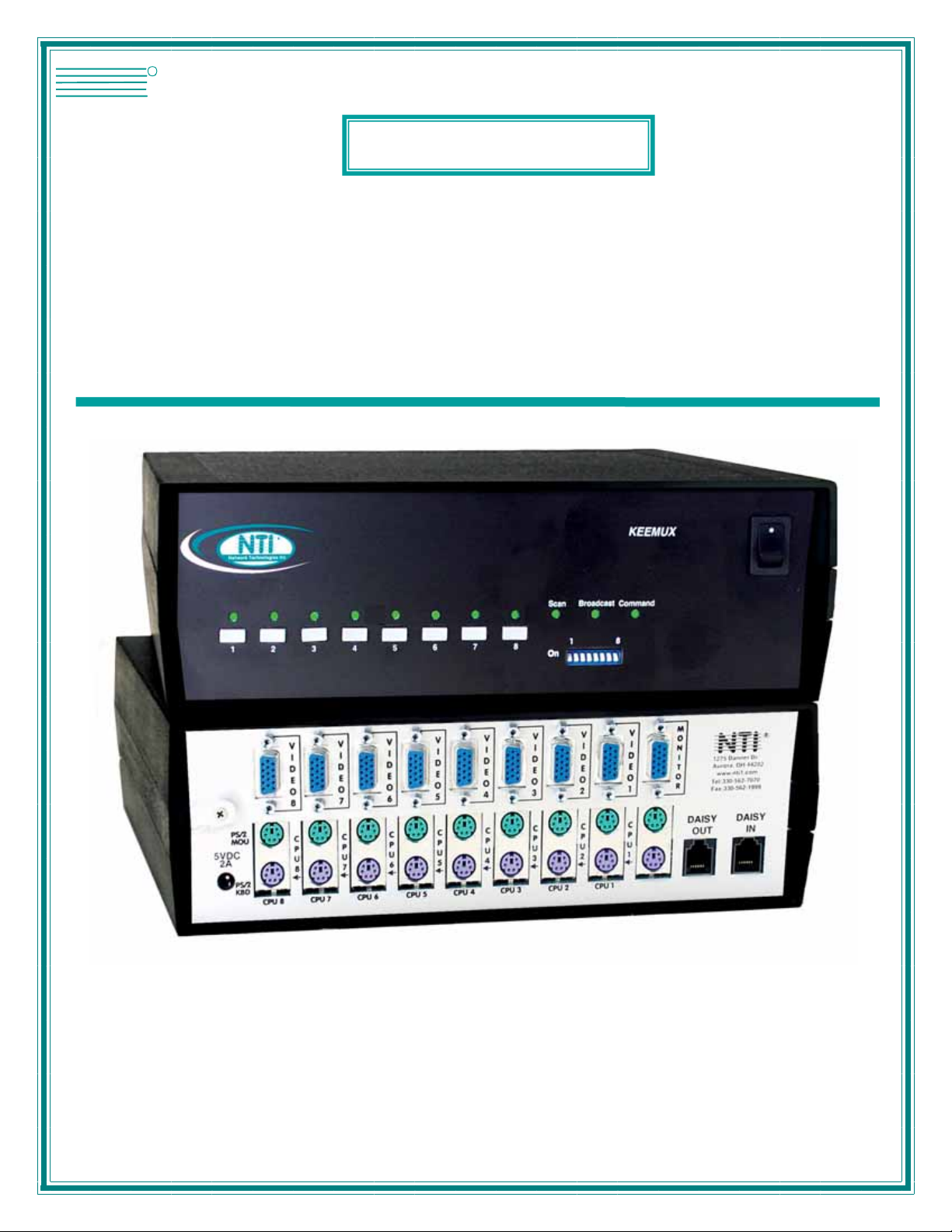
KEEMUX®Series
KEEMUX-Px
PS/2 KVM Switch
Installation and Operation Manual
MAN077 Rev Date 7/1/2007
Page 2

Warranty Information
The warranty period on this product (parts and labor) is two (2) years from the date of purchase. Please contact Network
Technologies Inc at (800) 742-8324 (800-RGB-TECH) or (330) 562-7070 or visit our website at
information regarding repairs and/or returns. A return authorization number is required for all repairs/returns.
COPYRIGHT
Copyright © 1999-2007 by Network Technologies Inc. All rights reserved. No part of this publication may be reproduced, stored
in a retrieval system, or transmitted, in any form or by any means, electronic, mechanical, photocopying, recording, or otherwise,
without the prior written consent of Network Technologies Inc, 1275 Danner Drive, Aurora, Ohio 44202.
CHANGES
The material in this guide is for information only and is subject to change without notice. Network Technologies Inc reserves the
right to make changes in the product design without reservation and without notification to its users.
http://www.networktechinc.com for
MAN077 Rev Date 7/1/2007
Page 3

TABLE OF CONTENTS
INTRODUCTION.............................................................................................................................................................1
MATERIALS....................................................................................................................................................................1
FEATURES AND FUNCTIONS.......................................................................................................................................2
INSTALLATION...............................................................................................................................................................3
Prepare To Connect ....................................................................................................................................................3
Make Connections.......................................................................................................................................................3
Power Up.....................................................................................................................................................................5
CASCADING...................................................................................................................................................................5
Limitations....................................................................................................................................................................5
Configuration ...............................................................................................................................................................6
Cascaded Installation ..................................................................................................................................................6
USING THE NTI KEEMUX PS/2 KVM SWITCH.............................................................................................................7
Front Panel Control......................................................................................................................................................7
Keyboard Control.........................................................................................................................................................8
Basic Command Mode .............................................................................................................................................8
Scan Mode................................................................................................................................................................9
Broadcast Mode........................................................................................................................................................9
Normal Mode ............................................................................................................................................................9
OSD CONTROL............................................................................................................................................................10
Security Option..........................................................................................................................................................10
Enabling the Security Feature...................................................................................................................................10
User Login Mode.....................................................................................................................................................10
Additional Modes Available With Security.................................................................................................................11
Administration Mode...............................................................................................................................................11
User Name List.......................................................................................................................................................11
System Access List.................................................................................................................................................12
User Access Functions..............................................................................................................................................12
OSD Command Mode ............................................................................................................................................12
Scan Mode..............................................................................................................................................................13
Broadcast Mode......................................................................................................................................................14
Normal Mode ..........................................................................................................................................................14
Edit Mode................................................................................................................................................................14
Search Mode...........................................................................................................................................................15
Maintenance Mode.................................................................................................................................................15
Help Mode...............................................................................................................................................................16
RS232 CONTROL.........................................................................................................................................................17
RS232 Connections and Configuration.....................................................................................................................17
Remote Connection..............................................................................................................
Baud Rate...............................................................................................................................................................17
Unit Address and Loop Back..................................................................................................................................18
Command Protocol....................................................................................................................................................19
KEYBOARD MAPPING.................................................................................................................................................20
HOW TO DISABLE OPERATING MODES...................................................................................................................21
Configuring The Jumper Block ..................................................................................................................................23
DDC SUPPORT............................................................................................................................................................23
AUDIO SUPPORT.........................................................................................................................................................24
DUAL VIDEO SUPPORT..............................................................................................................................................24
TROUBLESHOOTING..................................................................................................................................................25
..................................17
MAN077 Rev Date 7/1/2007
Page 4

TABLE OF FIGURES
Figure 1- Keyboard dip-switch configuration ......................................................................................................................................3
Figure 2- Connect the monitor to the KEEMUX.................................................................................................................................3
Figure 3- Connect the user keyboard and mouse..............................................................................................................................4
Figure 4- Connect a CPU to the KEEMUX.........................................................................................................................................4
Figure 5- Cascaded configuration......................................................................................................................................................5
Figure 6- Cable connections for cascading........................................................................................................................................6
Figure 7- Connect remote extension cables between cascaded units...............................................................................................7
Figure 8- Connections grouped by port number ................................................................................................................................9
Figure 9- Command Mode menu.....................................................................................................................................................12
Figure 10- Press <Ctrl> for more functions......................................................................................................................................13
Figure 11- Edit Mode screen............................................................................................................................................................14
Figure 12- Search Mode screen ......................................................................................................................................................15
Figure 13- Maintenance Mode screen .............................................................................................................................................15
Figure 14- RS232 connection with Matrix-Y-1 cable........................................................................................................................18
Figure 15- Pinout of Matrix-Y-1 cable..............................................................................................................................................18
Figure 16- Location of the jumper block...........................................................................................................................................21
Figure 17- Remove screws to open case.........................................................................................................................................21
Figure 18- Overhead view of inside of KEEMUX.............................................................................................................................22
Figure 19- Clear the jumper block for configuration access.............................................................................................................22
Figure 20- Place jumpers according to desired functionality............................................................................................................23
Figure 21- Control CPU audio with KEEMUX-P4-A.........................................................................................................................24
Figure 22- Connections for video cables on the KEEMUX-P4-DV...................................................................................................24
MAN077 Rev Date 7/1/2007
Page 5

NTI KEEMUX Series PS/2 KVM Switch
INTRODUCTION
The KEEMUX PS/2 KVM switch (KEEMUX) enables access to several IBM PC-AT, PC-AT Clone or PS/2 CPUs from one monitor,
keyboard and PS/2 mouse (up to 32 CPUs as a single switch or 152 CPUs when switches are cascaded). These CPUs can be
file servers, network managers, etc. Internal microprocessor driven circuitry allows all CPUs to be booted simultaneously and
error free with only one keyboard and mouse present. Port selection is accomplished through front panel push buttons or
commands typed on the keyboard. Port status LEDs continuously update on the front panel of the switch.
Available Options
• Switch models are available in 60 or 50 Hz, and 110 or 220V.
• OSD -On Screen Display feature will superimpose operating menus directly onto the monitor for security administration and
control. Add "-O" to the part number (i.e. KEEMUX-Px-O)
• RS232 support for alternative control using RS232 connection
• Audio support to enable user to connect stereo speakers to receive audio signals from connected CPUs- add "-A" to the part
number (i.e. KEEMUX-Px-A)
• Dual Video option supports CPUs with two video outputs. Add "-DV" to the part number (i.e.KEEMUX-Px-DV)
• DDC Support- for use with DDC enabled monitors. Add "-D" to the part number. (i.e. KEEMUX-Px-D)
See our catalog, visit our website at http://www.networktechinc.com, or contact an NTI sales representative at 800-742-8324 (800-
RGB TECH) or 330-562-7070 for more details.
Limitations
• The KEEMUX Px KVM switch is compatible with PS/2 mice and PS/2 CPU ports ONLY. Serial mice cannot be adapted for
use with the KEEMUX Px KVM switch.
• Serial ports on CPUs require the NTI VOPEX-IM9D for use with this switch.
Add "-RS" to the part number (i.e. KEEMUX-Px-RS)
MATERIALS
Materials Supplied with this kit:
• NTI KEEMUX Px KVM Switch (4,8,12,16,20,24, or 32 port)
• 120VAC or 240VAC at 50 or 60Hz-5VDC/2.0A AC Adapter
• Line cord, country specific
• This owners manual
Materials Not Supplied, but REQUIRED:
Monitor, keyboard, and mouse interface cables ARE REQUIRED but not supplied.
• MONITOR
• KEYBOARD
• MOUSE
Optional:
• KEYBOARD
and
MOUSE
Where:
xx is the length of the cable in feet
MM indicates male-to-male connector
All cables can be purchased from Network Technologies Inc by calling 800-RGB-TECH (800-742-8324) or (330)-562-7070.
- VEXT-xx-MM for video interface
- VKEXT-xx-MM for keyboard interface
- VKEXT-xx-MM for mouse interface
- VVKINT-xx-MM "Y"-cable for keyboard and mouse
interface
1
Page 6

NTI KEEMUX Series PS/2 KVM Switch
FEATURES AND FUNCTIONS
NTI
Networ k Technologies Inc
2345
1
1. Power ON/OFF switch
2. Mode LEDs- for visual indication of switch mode status
3. CPU Status LEDs- for visual indication of connection between the user and a specific CPU.
4. CPU Select Switches- push to manually switch to a specific CPU
5. Dip-switches- for configuring cascaded switches
6. MONITOR- 15HD female connector- for connection of the user monitor
7. VIDEO x- 15HD female connectors- for connecting video cables from CPUs
8. 5VDC- 2.0A- connection jack for the AC adapter
9. CPU x- 6 pin miniDIN female connectors- for connection of device cable(s) from CPU(s)
10. PS/2 DEVICES- 6 pin miniDIN female connectors- for connection of user device(s) (keyboard/mouse)
11. DAISY In/Out- for attaching interface cables (REXT-SR-xx) between slave switches and the master s witch
Rear View of KEEMUX-P8
-
5VDC
2A
V
I
D
E
O
8
C
P
U
+
8
8
Front Vie w of KEEMUX-P8
3
R
Broad
Scan
cast
678
4
7
V
V
V
V
V
I
I
I
CPU 5
I
D
D
E
E
O
O
5
4
C
C
P
P
U
U
4
5
D
D
E
E
O
O
7
6
C
C
P
P
U
U
6
7
CPU 6CPU 7CPU 8
V
I
I
D
D
E
E
O
O
3
2
C
C
P
P
U
U
2
3
CPU 2CPU 3CPU 4
9
2
21
Com
mand
1 8
On
5
6
NTI
1275 Danner Dr
Aurora, OH 44202
www.nti1.com
Tel:330-562-7070
Fax:330-562-1999
Mouse
Daisy Daisy
Out In
11
R
CPU 1
V
I
D
E
O
1
C
P
U
1
PS/2 DEVICES
10
M
O
N
I
T
O
R
Keyboard
Page 7
NTI KEEMUX Series PS/2 KVM Switch
INSTALLATION
Prepare To Connect
1. Before connecting the KEEMUX to the CPUs, make sure all CPUs, the monitor, and the KEEMUX are turned OFF.
WARNING! DAMAGE MAY OCCUR TO THE CPU IF POWER IS NOT DISCONNECTED BEFORE CONNECTING OR DISCONNECTING
!
CABLES.
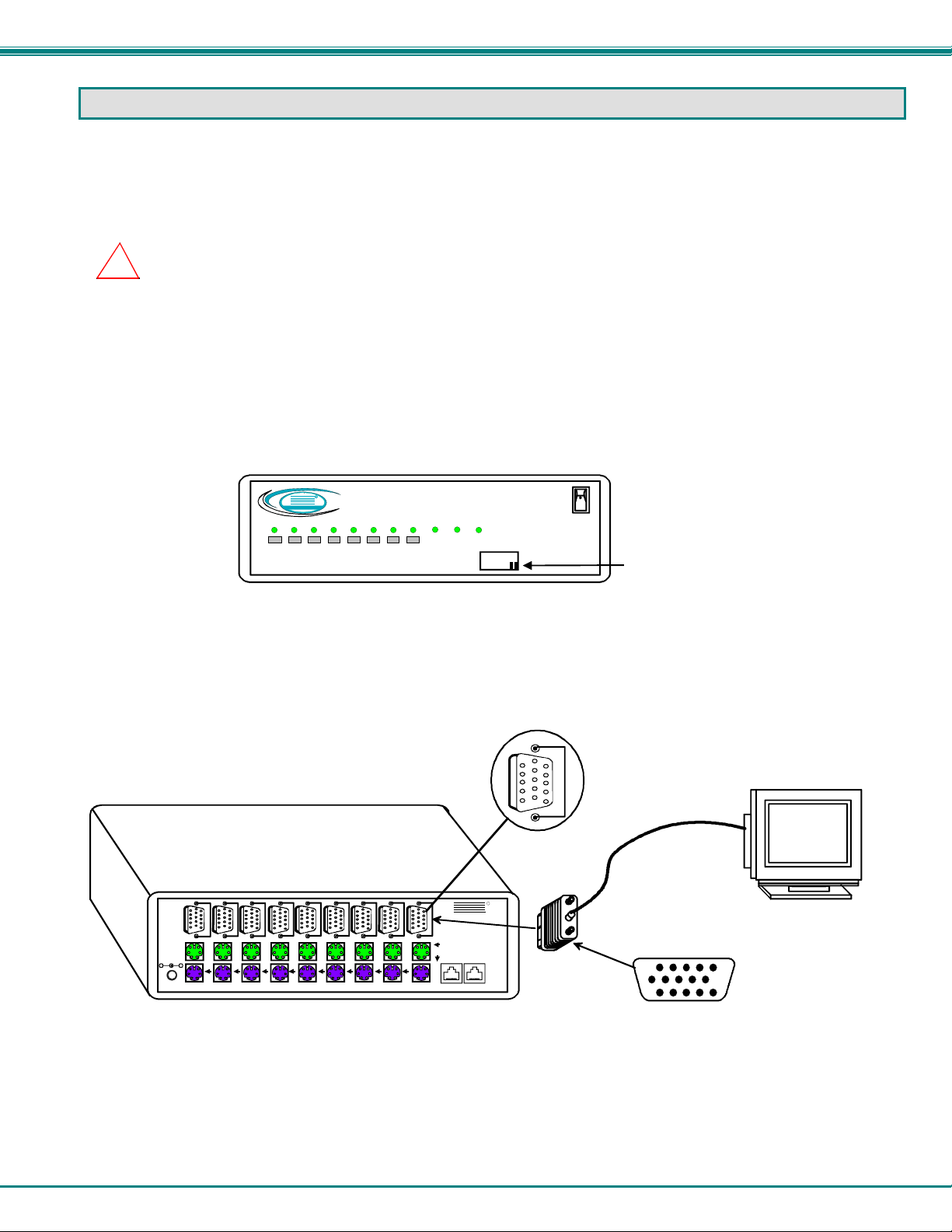
2. The dip-switches on the front panel are configurable for several tasks. Switches 1-6 are used for cascading actions (see
CASCADING on page 5) and switches 7 and 8 are for keyboard configuration. These keyboard configuration switches come
pre-configured with both in the “OFF” position. Do not change these settings, as this will cause the PS/2 keyboard to not
work.
FYI: Should switch 7 or 8 get changed to the “ON” position, it will be necessary to power-down the entire system
(including CPUs), change the dip-switches back to the “OFF” position, and then power the system back up. If it is
necessary to replace one PS/2 keyboard with another one, the keyboard can be hot-swapped without powering-down.
Refer to Fig. 1 for instructions on proper keyboard dip-switch configuration.
Networ k Technologies Inc
1
Figure 1- Keyboard dip-switch configuration
Front Vie w of KEEMUX- P8
R
NTI
Scan
2345
678
Broad
cast
On
Com
mand
1 8
Switch 7 - OFF
Switch 8 - OFF
Make Connections
1. Connect the monitor cable to the 15HD female port labeled “MONITOR” on the rear panel of the KEEMUX.
Rear View of KEEMUX-P8
15HD Female
Video Connector
-
5VDC
2A
+
V
V
V
V
V
V
I
I
I
CPU 5
I
D
D
E
E
O
O
5
4
C
C
P
P
U
U
5
4
I
D
D
E
O
8
C
P
U
8
D
E
E
O
O
7
6
C
C
P
P
U
U
6
7
CPU 6CPU 7CPU 8
V
I
I
D
D
E
E
O
O
3
2
C
C
P
P
U
U
2
3
CPU 2CPU 3CPU 4
CPU 1
V
I
D
E
O
1
C
P
U
1
PS/2 DEVICES
M
O
N
I
T
O
R
Keyboard
NTI
1275 Danner Dr
Aurora, OH 44202
www.nti1.com
Tel:330-562-7070
Fax:330-562-1999
Mouse
Dais y Daisy
Ou t In
R
Figure 2- Connect the monitor to the KEEMUX
M
O
N
I
T
O
R
15HD Male
Video Connector
VGA
Multi-Scan
Monitor
3
Page 8
NTI KEEMUX Series PS/2 KVM Switch
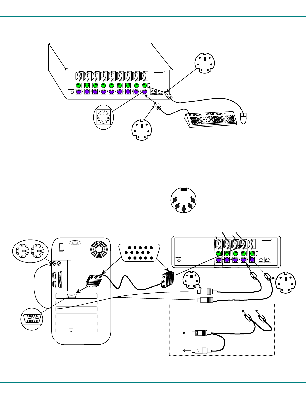
2. Connect the keyboard cable to the 6 pin miniDIN female port labeled “KEY BOARD” on the rear panel of the switch. Connect
the mouse cable to the 6 pin miniDIN female port labeled “MOUSE” on the rear panel of the KEEMUX.
Figure 3- Connect the user keyboard and mouse
3. Connect each CPU to the keyboard, monitor and mouse ports using VEXT-xx-MM for the monitor and VKEXT-xx-MM (2) for
the mouse and keyboard– REQUIRED (not supplied). See Fig. 4.
• Group the keyboard, monitor and mouse interface cables from each CPU.
• Make sure that cables from the first CPU are connected to the VIDEO 1 and CPU 1 MOUSE and KEYBOARD
connectors.
• Cables from the second CPU should connect to the VIDEO 2 and CPU 2 MOUSE and KEYBOARD connectors...etc.
NOTE: If an AT style keyboard connector is on a CPU, insert an
adapter cable (ADP-5D6MD-R) between the CPU and VKEXTxx-MM cable.
6 pin miniDIN
Female Connectors
Rear View of PS/2 CPU
15HD Female
Video Connec to r
Figure 4- Connect a CPU to the KEEMUX
Rear View of KEEMUX-P8
V
V
V
I
I
D
D
E
E
O
O
7
8
C
C
P
P
5VDC
2A
+
-
U
U
7
8
6 Pin miniDIN Female
I
D
E
O
6
C
P
U
6
CPU 5
CPU 6CPU 7CPU 8
Connector
V
I
D
E
O
5
C
P
U
5
V
V
I
I
D
D
E
E
O
O
4
3
C
C
P
P
U
U
3
4
V
I
D
E
O
2
CPU 2CPU 3CPU 4
15HD Male
Video Connec to r
M
V
O
I
N
D
I
E
T
O
O
1
R
C
C
P
P
U
U
1
2
CPU 1
PS/2 DEVICES
VEXT-xx-MM
R
NTI
1275 Danner Dr
Aurora, OH 44202
www.nti1.com
Tel:330-562-7070
Fax:330-562-1999
Mouse
Keyboard
Daisy Daisy
Out In
6 Pin mini DIN Male
Connector
AT Style Connector
To PS/2
CPU
4
6 Pin mini DIN Male
Connector
PS/2 KEYBOARD & MOUSE
Port assignments ( KEEMUX-P4 )
PORT 4
5VDC
2A
+
-
6 Pin miniDIN Male
Connector
PORT 3
V
I
D
E
O
4
C
P
U
4
PORT 2
V
I
D
E
O
3
C
P
U
3
PORT 1
CPU 2CPU 3CPU 4
V
I
D
E
O
2
C
P
U
2
VKEXT-xx-MM
VKEXT-xx-MM
To PS/2 KVM SWITCH
(PURPLE-KEYBOARD)
VVKINT-xx-MM
OPTIONAL "Y" CABLE
(GREEN-MOUSE)
(Use instead of two
VKEXT-xx-MM cables)
M
V
O
I
N
D
I
E
T
O
O
1
R
Mouse
C
Keyboard
P
Daisy Daisy
U
Out I n
1
CPU 1
PS/2 DEV I CES
R
NTI
1275 Danner Dr
Auro ra , OH 44 202
www.nti1.com
Tel:330-562-7070
Fax:330-562-1999
6 Pin miniDIN Male
Connector
Page 9
NTI KEEMUX Series PS/2 KVM Switch
Power Up
1. Turn the KEEMUX power ON first. The mode LEDs on the KEEMUX should flash twice.
2. Turn the monitor power ON.
3. Turn any or all of the CPUs ON.
FYI: Do not press any port buttons on the front panel until the PORT 1 light on the front panel illuminates.
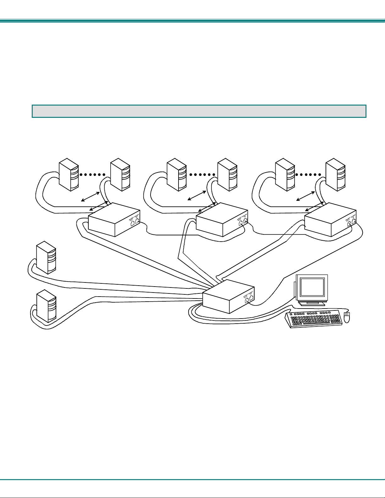
CASCADING
The KEEMUX switch can be expanded to access up to 152 CPUs by cascading multiple units together, as illustrated below. The
KEEMUX connected to the monitor and keyboard must be configured as the “master unit" (via dip-switches). Any switches
connected to the master unit must be configured as “slave units". All KEEMUXs are fully configurable for this expansion method.
The only additional hardware required is a set of keyboard, monitor, mouse, and RMT extension cables for each slave unit (see
Fig. 5 below).
PS/2 CPU
x 1...8
PS/2 CPU
x 1...8
VEXT-xx-MM
VVKINT-xx-MM
KEEMUX-P8
(slave uni t)
VEXT-xx-MM
VVKINT-xx-MM
KEEMUX-P8
(slave uni t)
REXT-SR-xx
PS/2 CPU
V
E
X
T
PS/2 CPU
-
V
V
V
V
E
X
T
-
x
V
x
V
-
M
K
M
I
N
T
-
x
x
-
M
M
x
x
-
M
M
K
I
N
T
-
x
x
-
M
M
M
-
M
x
-
x
T
X
V
E
V
K
I
N
T
x
-
x
-
M
M
V
E
X
T
-
V
x
x
V
-
K
M
I
N
M
T
-
x
x
-
M
M
(master unit)
V
KEEMUX-P8
Figure 5- Cascaded configuration
PS/2 CPU
x 1...8
VEXT-x x-MM
VVKINT-xx-MM
REXT-SR-xx
M
M
-
M
x
M
x
-
-
x
T
x
X
-
E
T
N
I
K
V
V
VGA
Multi-Scan
Monitor
KEEMUX-P8
(slave uni t)
R-
S
-
T
X
E
R
x
x
Limitations
a. All the slave units must be the same size.
b. Only 4, 8, or 16-port switches can be used as slave units.
c. Up to 8 slave units may be connected to form a maximum system size of 152 ports (1 x 32 port master + 8 x 16 port slaves).
d. Slave units must be added to the master unit in order (slave #1 to master’s port 1, slave #2 to master’s port 2, etc.).
FYI: Port 1 of the master unit (with a 4-port slave unit connected to it) will function and be controlled as ports 1-4 (1-8 for
an 8-port slave, 1-16 for a 16-port, etc.). Port 2 of the master unit (with a second 4-port slave unit connected) will
function and be controlled as port numbers 5-8 (9-16 for an 8-port slave, 17-32 for a 16-port slave, etc.). See Fig. 6 on
page 6.
e. All units must be powered OFF during configuration and interconnecting.
5
Page 10

NTI KEEMUX Series PS/2 KVM Switch
A
Configuration
All 4, 8, and 16-port units are configured using the 8-position dip-switch (located on the front of each unit) according to tables 1
and 2 below.
Front Panel Configuration Switches
Table 1 * (default settings)
Switch SW1 SW5 SW6
STAND-ALONE SWITCH OFF* OFF* OFF*
SLAVE ON OFF OFF
MASTER W/4-PORT SLAVES OFF OFF ON
MASTER W/8-PORT SLAVES OFF ON OFF
MASTER W/16-PORT SLAVES OFF ON ON
Table 2 * (default settings) Master & Slave SW2-4 Settings
SW2 SW3 SW4 Master with- Slave Setting
OFF* OFF* OFF* No Slave Attached N/A
OFF OFF OFF 1 Slave attached Slave Unit #1
OFF OFF ON 2 Slaves attached Slave Unit #2
OFF ON OFF 3 Slaves attached Slave Unit #3
OFF ON ON 4 Slaves attached Slave Unit #4
ON OFF OFF 5 Slaves attached Slave Unit #5
ON OFF ON 6 Slaves attached Slave Unit #6
ON ON OFF 7 Slaves attached Slave Unit #7
ON ON ON 8 Slaves attached Slave Unit #8
bout Table 2:
These switch settings are used by the slave(s) to
establish its identity (i.e. location in the group) to
the master.
On a master, the same switches are used to
configure the master for how many slaves are
attached to it.
Cascaded Installation
1. Attach all slaves consecutively to the master switch.
a. Perform steps 1 and 2 under INSTALLATION on page 4 for each slave unit.
b. Configure each switch as per the tables above under CONFIGURATION before proceeding.
c. With a VEXT-xx-MM cable, connect slav e #1 monitor port to master’s VIDEO 1 port.
d. With a VVKINT-xx-MM or (2) VKEXT-xx-MMs, connect slave #1’s PS/2 DEVICES ports to the
master’s CPU1 KEYBOARD and MOUSE ports.
e. Repeat steps c and d for each additional slave unit, keeping in mind that each slave will connect to the next ava ilable
master’s port (i.e. slave #2 to master’s VIDEO 2 and CPU 2 KEYBOARD and MOUSE, etc.). See Fig. 5 below.
If additional 4-PORT slaves are connected to
VIDEO, PS/2 MOU CPU, & PS/2 KBD CPU ports
3 & 4, they will function and be controlled as
CPU ports 9-12 and 13-16 respectively.
- ORIf individual CPUs are connected
to ports 3 & 4, they will function and
be controlled as CPU ports 9 & 10
respect ively.
CPU 7
CPU 8
5VDC
2A
+
-
SLAVE UNIT #2 (KEEMUX-P4)
For connection of CPUs 5-8
Figure 6- Cable connections for cascading
V
I
D
E
O
4
C
P
U
4
CPU 6
CPU 5
V
I
D
E
O
3
C
P
U
3
CPU 2CPU 3CPU 4
-
VEXT-xx-MM
5VDC
2A
+
V
V
I
I
D
D
E
E
O
O
2
1
C
P
U
2
CPU 1
C
P
U
1
PS/2 DEVICES
MASTER UNIT (KEEMUX-P4)
V
V
I
D
E
O
4
C
P
U
4
V
I
I
D
D
E
E
O
O
3
2
C
C
P
P
U
U
2
3
CPU 1
CPU 2CPU 3CPU 4
VVKINT-xx-MM
NTI
1275 Danner Dr
Aurora, OH 44202
www.nti1 .c om
Tel:330-562-7070
Fax:330-562-1999
R
5VDC
2A
+
-
M
O
N
I
T
O
R
Keyboard
Mouse
Daisy Daisy
Out In
6
CPU 1-4CPU 5-8
V
I
D
E
O
1
C
P
U
1
PS/2 DEVICES
CONNECT SLAVES FOR CASCADED
CPU CONNECTIONS
NTI
1275 Danner Dr
Aurora, OH 44202
www.nti1 .c om
Tel:330-562-7070
Fax:330-562-1999
CPU 4
R
CPU 3
V
I
D
E
O
4
C
P
U
4
CPU 2
V
I
D
E
O
3
CPU 1
C
P
U
3
CPU 2CPU 3CPU 4
V
I
D
E
O
2
C
P
U
2
CPU 1
M
O
N
I
T
O
R
Keyboard
Mouse
Daisy Daisy
Out In
SLAVE UNIT #1 (KEEMUX-P4)
For connection of CPUs 1-4
V
I
D
E
O
1
C
P
U
1
PS/2 DEVICES
M
O
N
I
T
O
R
Keyboard
NTI
1275 Danner Dr
Aurora, OH 44202
www.nti1 .c om
Tel:330-562-7070
Fax:330-562-1999
Mouse
Daisy Daisy
Out In
R
Page 11

NTI KEEMUX Series PS/2 KVM Switch
2. Connect Local CPUs to any remaining consecutive ports on the master as described under INSTALLATION on page 3.
3. Con nect the RMT extension cables:
a. With an RMT extension cable (REXT-SR-xx), connect the master’s “DAISY OUT” port to slave #1’s “DAISY IN” port.
b. With another RMT extension cable, connect slave #1’s “DAISY OUT” port to slave #2’s “DAISY IN” port. (See Fig. 8
below.)
c. Apply additional RMT extension cables until all slave units are connected together.
NOTE: If switches are not being cascaded, then the “DAISY IN” and “DAISY OUT” ports will not be used.
5VDC
2A
- +
Figure 7- Connect remote extension cables between cascaded units
SLAVE #2
R
V
V
V
V
I
D
E
O
8
C
P
U
8
V
I
I
I
I
D
D
D
D
E
E
E
E
O
O
O
O
7
6
5
4
C
C
C
C
P
P
P
P
U
U
U
U
4
6
7
5
CPU 5
CPU 6CPU 7CPU 8
M
V
V
V
O
I
D
E
O
3
C
P
U
3
CPU 2CPU 3CPU 4
NTI
I
I
N
D
D
1275 Danner Dr
I
E
E
Aurora, OH 442 02
T
O
O
www.nti1.com
O
Tel:330-562-7070
2
R
1
Fax:330-562-1999
Mouse
C
C
Keyb oard
P
P
Da isy Daisy
U
U
O ut In
2
1
PS/2 DEVICES
CPU 1
REXT-SR-xx
TO SLAVE 2
"DAISY IN"
V
I
D
E
O
8
C
P
5VDC
U
2A
+
-
8
SLAVE #1
V
V
I
I
D
D
E
E
O
O
7
6
C
C
P
P
U
U
6
7
CPU 5
CPU 6CPU 7CPU 8
V
V
V
I
I
I
D
D
D
E
E
E
O
O
O
5
4
3
C
C
C
P
P
P
U
U
U
3
4
5
V
V
I
I
D
D
E
E
O
O
2
1
C
P
U
2
CPU 1
CPU 2CPU 3CPU 4
M
O
NTI
N
1275 Danner Dr
I
Aurora, OH 44202
T
www.nti1.com
O
Tel:330-562-7070
R
Fax:330-562-1999
Mouse
C
Keyboard
P
Daisy Daisy
U
Out In
1
PS/2 DEVICES
DAISY OUT
5VDC
2A
+
-
V
V
I
I
D
D
E
E
O
O
8
7
C
P
U
8
"DAISY IN"
MASTER
V
V
I
I
D
D
E
E
O
O
6
5
C
C
C
P
U
7
P
P
U
U
5
6
CPU 5
CPU 6CPU 7CPU 8
REXT-SR-xx
V
V
V
I
I
D
E
O
4
I
D
D
E
E
O
O
3
2
C
C
C
P
U
4
P
P
U
U
2
3
CPU 1
CPU 2CPU 3CPU 4
V
I
D
E
O
1
C
P
U
1
PS/2 DEVICES
M
O
N
I
T
O
R
Keyboard
NTI
1275 Danner D r
Aurora, OH 4420 2
www.nti1.com
Tel:330-562-7070
Fax:330-562- 1999
Mouse
Daisy Dai sy
O ut In
R
TO SLAVE 1
R
USING THE NTI KEEMUX PS/2 KVM SWITCH
Control over the CPUs attached to the NTI KEEMUX is achieved through operation of the KEEMUX. Once the KEEMUX is
properly connected, the KEEMUX will enable a connection to be made between the CPUs attached to its CPU x, and VIDEO x
ports and the keyboard, monitor, and mouse attached to the PS/2 DEVICES and MONITOR ports. The LEDs on the control
panel of the KEEMUX will illuminate depending on which port (and associated CPU) is being connected to the keyboard, monitor,
and mouse. The choice of which CPU will be connected to the keyboard, monitor, and mouse is determined by controlling the
KEEMUX either through the front control panel on the KEEMUX, by keyboard control, or by optional methods such as RS232 or
an On Screen Display (OSD).
Front Panel Control
There is a touch-switch and LED on the front panel of the KEEMUX for each connected CPU. Pressing any touch-switch on
the front panel of the KEEMUX will connect the selected CPU to the keyboard, monitor, and mouse.
Holding down any front panel touch-switch for more than 2 seconds will cause the KEEMUX to cycle through all modes of
operation: COMMAND, SCAN, BROADCAST, and NORMAL (described on pages 9 and 10). Three LEDs on the front panel
indicate when these modes are enabled. Release the touch-s witch when the desired mode is enabled. When no mode LEDs are
illuminated the user is in Normal Mode controlling directly the CPU to which the user is connected through the KEEMUX.
7
Page 12

NTI KEEMUX Series PS/2 KVM Switch
Keyboard Control
Keyboard control of the KEEMUX can be achieved using either of two methods:
• Basic Command Mode- operated strictly by using keyboard commands as instructed belo w. Basic Command Mode is only
applicable if the OSD option is not built into the switch.
• OSD Command Mode (optional)- operated using the keyboard and mouse in conjunction with On Screen Display (OSD)
menus superimposed onto the monitor. If OSD is built in, use the menus as instructed on page 12.
By pressing <Ctrl> + <`> (accent key), the user can enter Command Mode (either Basic, or OSD). Once in Command Mode,
typing a series of commands will cause the KEEMUX to connect the user to any one CPU to which the KEEMUX is attached.
Once finished, pressing the <Esc> key will exit Command Mode.
Basic Command Mode
In order to control the KEEMUX with the keyboard, Command Mode must be enabled. To enter Command Mode from the
keyboard:
Press
Ctrl
+
NOTE: IF THE OSD FEATURE HAS BEEN INSTALLED, PROCEED DIRECTLY TO “OSD CONTROL”
ON PAGE 10. If not, continue with the instructions for controlling the KEEMUX as detailed below.
When the COMMAND LED is illuminated, all 3 status lights on the keyboard will illuminat e to indicate that Command Mode is
enabled and the following functions are available: (NOTE: The user must exit Command Mode in order to type to a CPU. To exit
Command Mode, press <Esc>.)
Command Functions
Function: Keystroke:
Increment Port
Decrement Port 1
Toggle Scan Mode
ON and OFF
Toggle Broadcast
Mode ON and OFF
Sets scan time-out
period for each port.
Selects a specific
port
Exit Command Mode
1
If the SCAN LED is ON, pressing → or ← will cause the switch to select the next active port.
NOTE: The “port” mentioned in the “Command Functions” above refers to the combination of the video (VIDEO x), mouse and
keyboard (CPU x) of like numbers that a CPU is connected to (i.e. the CPU that is connected to VIDEO 1 and CPU 1 will be
identified as Port 1 or P01). (See Fig. 8 on page 9.)
1
I
D
or
or
(select the next higher port
ex. 05 06)
(select the next lower port
ex. 02 01)
S
B
T
P
Esc
(0-2)
-
x
(0-9)
-
x
(0-9)
-
x
(0-9)
-
x
(Pxx would be P01, P02, etc.)
(ACCENT
~
KEY)
`
`
KEY SYMBOLS LEGEND:
or
PRESS EITHER KEY
CHORDED SEQU E NCE- PRESS CONSE CUTIVE LY
+
AND KEEP KEYS PR ESSED UNTIL ALL ARE PRESSED.
PRESS CONSECUT I VELY
-
(0-9)
-
x
(xxx f ro m 002 to 255. ie. t 002
would set the time out period
for 2 seconds)
8
Page 13

NTI KEEMUX Series PS/2 KVM Switch
Figure 8- Connections grouped by port number
Please note: If the switches are being cascaded (such as that illustrated in Fig. 5 on page 5 u nd er “Cascading”), make
note of which port each of the CPUs is connected to on each slave and which port each slave is connected to on the
master. .
• The ports on the slave connected to the port 1 port on the master would be numbered 01-04 with multiple
KEEMUX-P4s, the ports on the slave connected to port 2 would be numbered 05-08 (with multiple KEEMUX-P8s
they would be 01-08, and 09-16, etc.)
• A connection to the CPUs from the keyboard would be achieved by typing the appropriate port number. (See
Fig. 6 on page 6.)
• No programming of the KEEMUX is necessary to achieve this control.
• When cascading, if not all of the ports are used on each slave attached to your system, THE PORT NUMBER(S)
ASSOCIATED WITH THE UNUSED PORT(S) WILL NOT BE ACCESSIBLE when trying to control the switches
connected to the system. (I.e. if ports 7 and 8 are not used on the first slave and an attempt is made to
connect to ports 7 or 8 while in Command Mode, the KEEMUX will ignore the attempt. )
-
Port assignments ( KEEMUX-P4 )
5VDC
2A
PORT 3
PORT 4
V
I
D
E
O
4
+
C
P
U
4
PORT 1
PORT 2
V
I
D
E
O
3
C
P
U
3
CPU 2CPU 3CPU 4
V
I
D
E
O
2
C
P
U
2
CPU 1
V
I
D
E
O
1
C
P
U
1
PS/2 DEVICES
M
O
N
I
T
O
R
Keyboard
NTI
1275 Danner Dr
Aurora, OH 4420 2
www.nti1.com
Tel:330-562-7070
Fax:330-562-1999
Mouse
Daisy Daisy
Out In
R
Scan Mode
When in Scan Mode the KEEMUX scans each port with a CPU powered-ON. (The SCAN LED on the front panel will illuminate
and remain ON while in Scan Mode.) The port with the CPU powered-ON remains active while in use. When the s witch becomes
idle for the configured time-out period (default time-out period is 5 seconds) the switch will connect to the next powered-ON CPU
port. See Command Mode section above for configuring the scan time-out period.
FYI: The keyboard and mouse must remain idle for the full scan time-out period before the switch will connect to the next
active port.
Broadcast Mode
(Use with extreme caution or commands intend ed for one CPU will be sent to all CPUs)
Broadcast Mode allows the operator to send keystrokes to all active CPUs simultaneously. However, Broadcast Mode has some
critical requirements.
• BROADCAST LED must be OFF when booting any attached CPUs.
• BROADCAST LED must be ON and COMMAND LED must be OFF for keystrokes to reach attached CPUs.
Normal Mode
When all of the KEEMUX mode LEDs are OFF the user is in Normal Mode, controlling the CPU to which the user is connected
through the KEEMUX.
9
Page 14

NTI KEEMUX Series PS/2 KVM Switch
OSD CONTROL
(Optional)
OSD superimposes a menu system on the user’s video screen with a list of all connected CPUs. OSD allows CPUs to be named
(with up to 12-character names). OSD then allows selection of CPUs by that name. Connected CPUs can be listed by name or
by port number. OSD Search Mode enables the user to type in the first few characters of the CPU's name and the OSD will locate
it. Help screens assist with all OSD functions.
Security Option
The security option of the OSD Control enables an administrator to control access to the CPU ports for each user. Up to 24 users
can be created. These users have controlled access to any CPU. Only the administrator can activate or deactivate the secur ity
features. Security can be activated from the Maintenance Mode menu (page 18) with a successful administrator login for
verification purposes. Furthermore, the administrator can set a maximum idle time value after which the current user will be
logged out and the login screen displayed. This time out does not function while the OSD is active. The current security status,
idle time out, and scan dwell time are all saved and will be restored whenever power to the switch is cycled OFF, then ON.
Enabling the Security Feature
To enable the security feature the administrator must first enter Command Mode from the keyboard using the se quence <Ctrl> +
<`> (accent key). The OSD menu will automatically appear on the monitor in addition to illuminating the Command Mode indicator
LED on the KVM switch. This provides a visual way to control the KEEMUX using the keyboard, monitor, and mouse.
The administrator , when setting the KEEMUX up for the first time, may want to proceed directly to the ADMINISTRATION
Mode by typing <CTRL> + <M> , then <A>, and then <Y>.
The factory settings are:
• default user name = ADMINISTRATOR
• default password = ADMINISTRATOR
FYI: The user name for administrator cannot be changed from "ADMINISTRATOR"
Once logged-in, follow the instructions on page 14 for setting up users and changing the password. Once the password is setup,
if it is lost or forgotten, the administrator will have to contact NTI for assistance on clearing the password and set it up again.
Within the ADMINISTRATION Mode the administrator can setup each of the users and the limitations of their use of the individual
CPUs on the system.
When a standard user powers up the system a security screen may appear as setup by the administrator. The user will
need to login to the system by following the instructions below for the USER LOGIN. If the user does not know the appropriate
user name and password (setup by the administrator), contact the system administrator for this information. Once logged-in a
user can follow the Command Functions described on page 15 to control the system of CPUs within the limitations as set by the
administrator.
User Login Mode
User Login Mode requires a user to login with a user name and password from the list created by the administrator. Access to
the functions of the KEEEMUX will not be allowed until a user has logged in.
Function: Keystroke:
Adds a character to the
user name/password
Removes previous character
from the user name/password
A-Z
(Type any alphabetical or numeric character)
0-9
Backspace
10
Page 15

NTI KEEMUX Series PS/2 KVM Switch
User Login Mode (Cont'd)
Function: Keystroke:
Submit user name/password
Exit User Login Mode and return
to previous mode. This function
is only available if security is
not currently active.
.
Esc
Enter
If the password submitted is incorrect, the user will not be
able to proceed.
If the password submitted is correct, the user will proceed
to the maintenance menu for additional feature options.
Additional Modes Available With Security
NOTE: The three modes that follow are only available if the administrator is log ged in.
Administration Mode
Administration Mode allows the administrator to use the following functions:
Function: Keystroke:
Change the administrator’s
password
Enter User Name List Mode
Disable security
Selects the idle time in seconds
Exit Administration Mode and
return to previous mode
C
U
S
T
Esc
(0-2)
-
x
(0-9)
-
x
-
(xxx from 000 to 255. ie. t002
(0-9)
would set the time-out period
x
for 2 seconds. 000 will disable it)
User Name List
The User Name List displays the list of users and provides control for adding new users, changing or assi gning user passwords,
and changing access rights for any given user. User names may be up to 12 characters long, may not contain spaces, and are
not case sensitive. Passwords may be up to 15 characters long, may not contain spaces, and are case sensitive.
Function: Keystroke:
Edit the highlighted user’s
System Access rights
Enter Edit Mode to add/change/
remove users
Change the highlighted user’s
password
Exit the User Name List and
return to previous mode
Esc
Ctrl
Ctrl
Ctrl
+
+
+
A
E
P
11
Page 16

NTI KEEMUX Series PS/2 KVM Switch
System Access List
The System Access List displays a list of numbers representing the ports so the administrator can change access rights to the
ports for the selected user. The user’s name is displayed at the top of the access list. The mouse is used to change access rights
by clicking on a given number to toggle a port’s status. A user that has access to a port can connect to that port and control the
CPU connected to that port when in Normal Mode.
Function: Keystroke:
Save the changes to the access
list and return to previous mode
Exit the System access list without
saving and return to previous mode.
Enter
Esc
User Access Functions
Introduction
The OSD menu enables a user to name the CPUs connected to the KEEMUX and connect to them using that name from a single
keyboard and mouse. The OSD is positioned on the user's monitor, displaying 8 CP U names at a time. The screen can be used
for switching as well as editing the CPUs’ names. Through the OSD menu, the user can control the KEEMUX to cycle through all
modes of operation: COMMAND, SCAN, BROADCAST and NORMAL. LEDs on the front panel will illuminate to indicate when
these modes are enabled.
OSD Command Mode
If the OSD option is installed, when entering the Command Mode from the keyboard using the <Ctrl> + <`> (accent key),
the On Screen Display menu will automatically appear on the monitor in addition to illuminating the indicator LEDs on the KVM
switch. This provides a visual way to control the KEEMUX using the keyboard, monitor, and mouse.
The list below describes the command functions available from the keyboard within the OSD mode of control after entering into
Command Mode and while the COMMAND LED is illuminated:
Function: Keystroke:
Select the previous port
Select the next port
Enable/disable Scan Mode
Enable/disable Broadcast Mode
Enter Edit Mode
Enter Maintenance Mode
Display Help Menu (available with
every control mode)
Figure 9- Command Mode menu
Ctrl
F1
Ctrl
Ctrl
Ctrl
+
+
+
+
S
B
E
M
12
Page 17

NTI KEEMUX Series PS/2 KVM Switch
OSD Command Mode (Cont'd)
Function: Keystroke:
Sets scan time-out on
each port
Selects a specific port
Enters Search Mode and adds a character
to search string and selects the CPU’s
name that matches best.
Selects the first port on the switch
Selects the last port on the switch
Switch to a selected port
Exit OSD Command Mode
The mouse can also be used to control Command Mode. The mouse
cursor can be moved to the Scan, Help, and Exit fields where the user
can then click on the left mouse button to perform that function. Ports
listed on the screen can be selected by moving the cursor onto that port
and clicking. Clicking twice on a selected port will switch to that port
and exit Command Mode. To change the displayed ports on the screen
simply click on the up and down arrows located to the right of the port
names displayed.
Figure 10- Press <Ctrl> for more functions
Ctrl
A-Z
0-9
Home
End
Esc
T
+
Ctrl
(Type any alphabetical or numeric character)
Enter
+
P
(0-2)
-
x
(0-9)
-
x
(0-9)
-
-
Note: The user must exit
Command Mode to type to a CPU.
To exit Command Mode, either
hold down any touch-switch on the
front panel for more than 2
seconds, OR press <ESC>.
x
-
(0-9)
(Pxx would be P01, P02, etc.)
x
(xxx from 002 to 255. ie. t002
(0-9)
would set the time-out period
x
for 2 seconds)
Scan Mode
When in Scan Mode the switch scans to each port with a CPU powered-ON. (The SCAN LED on the front panel will illuminate a nd
remain ON while in Scan Mode.) To enter Scan Mode press <Ctrl> + <S> from Command Mode. The port with the CPU
powered-ON remains active while in use. When the switch becomes idle for the configured time-out period (d efault time-out
period is 5 seconds) the switch will connect to the next powered-ON CPU port. See Command Mode section ab ove for configuring
the scan time-out period.
NOTE: The keyboard and mouse must remain idle for the full scan time-out period before the switch will connect to the
next active port.
13
Page 18

NTI KEEMUX Series PS/2 KVM Switch
Broadcast Mode
(Use with extreme caution or commands intended for one CPU will be sent to all CPUs)
Broadcast Mode allows the operator to send keystrokes to all active CPUs simultaneously (even those CPUs the user cannot
connect to due to lack of security access ).
To enter Broadcast Mode press <Ctrl> + <B> from Command Mode. Broadcast Mode is
indicated by the illumination of the BROADCAST LED on the front panel. The BROADCAST LED will remain ON while in
Broadcast Mode. However, Broadcast Mode has some critical requirements:
• BROADCAST LED must be OFF when booting any attached CPUs.
• BROADCAST LED must be ON and COMMAND LED must be OFF for keystrokes to reach attached CPUs.
Normal Mode
When all of the KEEMUX mode LEDs are OFF the user is in Normal Mode, controlling the CPU to which the user is connected
through the KEEMUX.
Edit Mode
Edit Mode allows the user to modify the names of the CPUs connected to the switch. Names of CPUs can be up to 12 characters
in length. To enter Edit Mode press <Ctrl> + <E> from Command Mode. When in Edit Mode, multiple keystroke combinations
are not valid (<SHIFT>+<P>, <CTRL>+<P>, <ALT>+ <P>, and <P> will all type a “P” to the displa y - lower case letters cannot be
typed). After changes have been made the user will be prompted by the menu to save the changes. Answer "Y" to save changes
and answer "N" to continue using previously entered port names.
Function: Keystroke:
Move cursor one position
to the right
Move cursor one position
to the left
Previous port
Next port
Selects the first port on
the switch
Selects the last port on
the switch
Figure 11- Edit Mode screen
Toggles between insert
and overstrike
Erase current character
Erase previous character
When finished making changes in Edit Mode, press <Enter> and a prompt will appear to press either <Y> to save the changes or
<N> to continue making changes without saving the changes just made. If the <ESC> key is pressed instead of <Enter>, all
changes made will be cancelled and the display will return to the previo us menu.
Home
End
Insert
Delete
(The character either gets inserted and the remainder of the name
gets shifted to the right, OR the current character gets overwritten.)
Backspace
14
Page 19

NTI KEEMUX Series PS/2 KVM Switch
Search Mode
Search Mode allows the user to enter and maneuver through a list of CPU names. As the user types, the best matching CPU
name is selected. The list of CPUs may also be searched for a specific (or similar) name. From Command Mode, type any
alphabetical or numeric character to enter Search Mode. The following commands are valid when the search option has been
invoked from Command Mode.
Function: Keystroke:
Erase previous character
in search name
Move cursor one position to
the right in search name
Move cursor one position to
the left in search name
Select previous port
Select next port
Figure 12- Search Mode screen
Add a character to the search
string and select the best
matching CPU name
Exit Search Mode, return to
Command Mode
Switch to selected port
Backspace
A-Z
(Type any alphabetical or numeric character)
0-9
Esc
Enter
Maintenance Mode
Maintenance Mode allows a user to customize the On Screen Display to their requirements. To enter Maintenance Mode press
<Ctrl> + <M> from Command Mode.
Function: Keystroke:
Reset all of the port names
Toggle between numeric and
alphabetic listing of ports
Move On Screen Display (OSD)
window up on monitor
Move OSD window down on
monitor
Move OSD window to the right
Move OSD window to the left
Figure 13- Maintenance Mode screen
R
L
15
Page 20

NTI KEEMUX Series PS/2 KVM Switch
Maintenance Mode (Cont’d)
Function: Keystroke:
Make OSD window taller
Make OSD window shorter
Change user password.
(Present only when a standard
user is logged in.)
Log current user out and return
to User Login Mode.
Activate security features
Present only when security is
available but not active.
Enter Administration Mode.
Option present only when administrator
is logged in.
Save OSD window parameters
for the port
Return to Command Mode
.
T
S
P
Q
A
Enter
Esc
NOTE: If activating security features, the user will
be prompted for a “Y” (yes) or “N” (no) to confirm
the menu choice, at which point the user will be
asked for a username and password before
continuing. Only the administrator can activate the
security features.
Help Mode
This mode displays a list of commands with a short explanation of their function. These lists are organized in pages for each
mode (i.e. COMMAND, EDIT, SEARCH, and HELP).
allow the user to quickly obtain information on any command
Function: Keystroke:
View the previous page of help
if available
View the next page of help
if available
Exit HELP and return to previous
mode
Page
Up
Page
Down
Esc
To enter Help Mode press <F1> from Command Mode. The following options
.
16
Page 21

NTI KEEMUX Series PS/2 KVM Switch
RS232 CONTROL
(Optional)
Rear View of KEEMUX-P4-RS
RS232
M
V
V
V
RS232 Connections and Configuration
-
5VDC
2A
V
I
D
E
O
4
R
NTI
1275 Danner Dr
+
Aurora, OH 44202
www.nti1.com
Tel:330-562-7070
Fax:330-562-1999
C
P
U
4
I
I
D
D
E
E
O
O
2
3
C
C
P
P
U
U
2
3
CPU 2CPU 3CPU 4
CPU 1
I
D
E
O
1
C
P
U
1
PS/2 DEVICES
O
N
I
T
O
R
Keyboard
1 2 3 4 5 6 7 8
Mouse
Dais y Daisy
Ou t In
OFF
ON
Remote Connection
The RS232 Interface (optional) is designed to meet the RS232C standard and can be controlled from a ny CPU or other controller
with an RS232 communications port. The pin-out for the DB-9 connector(s) on the unit is as follows:
RS232 CONNECTOR (DB-9 FEMALE)
PIN SIGNAL FUNCTION
1 CD Carrier Detect
2 TXD Transmit data (RXD at host)
3 RXD Receive data (TXD at host)
4 DTR Data terminal ready
5 GND Signal ground
6 DSR Data set ready
7 RTS Request to send
8 CTS Clear to send
9 - No connection
Note: Security must be disabled or user access granted on the port(s) to be selected by RS-232 control.
On the DB-9 female connector, pins 1 (DCD), 4 (DTR), and 6 (DSR) are shorted and pins 7 (RTS) and 8 (CTS) are shorted.
Therefore, host handshaking is bypassed and TXD and RXD are the only active signals. A straight through DB-9 cable (not null
modem) will work for most CPUs. To daisy chain multiple units, a Matrix Y-1 cable is used (see page 18) for each KEEMUX in the
chain. The last unit in the chain should have DIP switch 1 ON (see table under "Unit Address and Loop Back" on pag e 18).
Baud Rate
The baud rate can be changed by powering down the unit, changing the 8 position RS232 dip switch on the rear of the KEEMUX,
and then powering back up. This table shows how to set the baud rate.
DIP SWITCH BAUD RATE
4 3 2
OFF OFF OFF 300
OFF OFF ON 600
1 2 3 4 5 6 7 8
OFF ON OFF 1200
OFF ON ON 2400
ON OFF ON
ON ON OFF
9600
ON ON ON
17
OFF
ON
Page 22

NTI KEEMUX Series PS/2 KVM Switch
Unit Address and Loop Back
To allow multiple units to be controlled from a single CPU port, the RS232 control interface is designed to allo w "daisy chaining"
up to 15 units. By setting the appropriate RS232 dip switches, each unit can be given a unique addr ess (1-15). Then the unit will
only respond to commands on the bus if its address is embedded in the command. Use the table below to set the unit address.
DIP SWITCH UNIT ADDRESS
8 7 6 5
OFF OFF OFF OFF 0 (not valid)
OFF OFF OFF ON 1
OFF OFF ON OFF 2
OFF OFF ON ON 3
OFF ON OFF OFF 4
OFF ON OFF ON 5
OFF ON ON OFF 6
OFF ON ON ON 7
ON OFF OFF OFF 8
ON OFF OFF ON 9
ON OFF ON OFF 10
ON OFF ON ON 11
ON ON OFF OFF 12
ON ON OFF ON 13
ON ON ON OFF 14
ON ON ON ON 15
Note: In order to connect multiple KEEMUX units together a Matrix-Y-1 cable must be used. (See Fig. 14.) See Fig. 15 for
the pinout of the Matrix-Y-1 cable. The Matrix-Y-1 cable is available from Network Technologies Inc.
CPU
RS232
Serial Port
RS232
NTI
SWITCH
First Unit
Matrix-Y-1
Matrix-Y-1 Matrix-Y-1
RS232
NTI
SWITCH
Second Unit
RS232
NTI
SWITCH
Last Unit
Figure 14- RS232 connection with Matrix-Y-1 cable
Figure 15- Pinout of Matrix-Y-1 cable
Wiring Schematic of Matrix-Y-1 cable
9D Female9D Male 9D Male
(Unit #1)
(Source)
(Unit #2)
23
33
555
Not connected to
source connector
22
7
Jumper
8
1
Jumpers
4
6
18
Page 23

NTI KEEMUX Series PS/2 KVM Switch
Command Protocol
Host controller commands supported by the unit are defined below.
Notes:
• All commands should be terminated with an <Enter> (ASCII 13) denoted by <CR>. When a
command is sent, the entire string is echoed back to the CPU along with a response from the
addressed unit as shown in the command definitions. Unit response will be sent within 500 msec
after <CR>.
• Use a program that will send an entire command line all at once, not character by character. Do not use the program
HyperTerminal in WINDOWS, as it sends each character one at a time.
• All characters should be upper case, and all numbers below 10 should have a leading 0 (ex: 1 = 01).
• For units with one USER port, use 01 for the USER select.
RS - reset unit(s) to default power-up configuration
FORMAT: RS AA<CR>
RS = "reset unit" command followed by at least one space
AA = unit address; if 00, all units on the bus will be reset and no response will be
returned
RESPONSE: *<CR> if command received and executed OK
-OR-
?<CR> if syntax or transmission error occurred
Note: The RS command does not change the actual configuration.
CS - change single USER channel
FORMAT: CS AA,XX,YY<CR>
CS = "change single output" command followed by at least one space
AA = unit address
XX = input/CPU to connect
YY = output/USER to change
RESPONSE: *<CR> (command received and exec uted OK)
-OR-
?<CR> (syntax or transmission error occurred)
CA - change all output channels
FORMAT: CA AA,XX<CR>
CA = "change all outputs" command followed by at least one space
AA = unit address
XX = input /CPU to connect to all outputs/USERS
RESPONSE: *<CR> (command received and exec uted OK)
?<CR> (syntax or transmission error occurred)
19
Page 24

NTI KEEMUX Series PS/2 KVM Switch
RO - read single USER channel
FORMAT: RO AA,XX<CR>
RO = "read output" command followed by at least one space
AA = unit address
XX = output/USER to read
RESPONSE: *<CR> (command received and exec uted OK)
XX<CR> (XX = input/CPU connected)
-OR-
?<CR> (syntax or transmission error occurred)
RU - read unit size
FORMAT: RU AA<CR>
RU = "read unit size" command followed by at least one space
AA = unit address
RESPONSE: *<CR> (command received and exec uted OK)
XX,YY<CR> (XX = # of CPU’s, YY = # of USERS)
-OR-
?<CR> (syntax or transmission error occurred)
KEYBOARD MAPPING
The keyboard configuration of each CPU is saved in the KEEMUX. For example, if the CPU attached to Port 4 had CAPS LOCK
and NUM LOCK selected the last time that CPU was accessed, then they will automatically be set when Port 4 is accessed again.
20
Page 25

NTI KEEMUX Series PS/2 KVM Switch
HOW TO DISABLE OPERATING MODES
The operating modes of the KEEMUX can be disabled if a user desires to do so. The Command Mode can be disabled
which would also disable the Scan and Broadcast Modes, or, the Scan and/or Broadcast Modes can be individuall y disa bled
leaving the other features in Command Mode enabled.
To disable these operating modes, the user must get access to the jumper block. This block is located close to the dipswitches on the circuit board the keyboards plug into (called the digital board) inside the KEEMUX. (See Fig. 16.)
Rear Pane l
Disconnect video
ribbons here
LED Board
Front Panel
Overhead view of video board on top of digital board.
Figure 16- Location of the jumper block
If the unit is a rackmount style, the digital board is located directly beneath the cover of the unit, requiring the user to only remove
the 10 screws from the cover to get access. With the cover removed, the jumper block will be easy to locate. Follow the
instructions under "CONFIGURING THE JUMPER BLOCK" on page 22 to disable the desired mode(s).
If the unit is in a plastic case, the digital board is located on the bottom of the case, requiring the user to partially disassemble the
unit to gain access to the jumper block.
For models KEEMUX-Px in a plastic case:
1. Make sure the KEEMUX is completely disconnected from all CPU components. Be sure to unplug the KEEMUX from
the electrical outlet.
2. Remove the two philips-head screws from the underside of the KEEMUX and set the KEEMUX on a firm and flat
surface, bottom down. (See Fig. 17.)
Figure 17- Remove screws to open case
3. Remove the top half of the plastic case from the KEEMUX.
15HD Connector
Video Board
Digital Bo a r d
The jumper block is located
below the LED board.
Philips-head screws
holding the plastic case
together
View of bottom of plastic case
Closeup view of jumper block on digital board.
JUMPER BL O C K
L
K
B
S
C
C
R
C
D
M
D
A
E
D
C
N
DIP SWITCHES
21
Page 26

NTI KEEMUX Series PS/2 KVM Switch
NOTE: Before proceeding, it is important to discharge any static charge you may be carrying by touching any large
metal object (away from the KEEMUX).
4. The first visible circuit board, the uppermost board, is the video board. Along the back of the video board
are between 3 and 5 video ribbons (depending on how many monitors the unit is designed to connect to)
connecting the video board to a circuit board on the rear panel with 15HD connectors on it. Disconnect
the flat ribbon cables from the video board to each header on the rear panel. Take note as to where they
go for re-assembly later. Do not disconnect them from the video board headers. (See Fig. 18.)
5. There are 4 nuts that secure the video board to standoffs. Remove the 4 nuts.
Rear Panel
Disconnect video
ribbons here
LED Boar d
Front Panel
Overhead view of video board on top of digital board.
Figure 18- Overhead view of inside of KEEMUX
To avoid further more difficult disassembly, the video board and front panel will be removed from the KEEMUX as an assembly.
6. Carefully loosen the video board from the standoffs. With it loosened, grasp firmly the video board and
front panel at the same time and slide the front panel up out of the slots in the plastic case that support it.
Once clear of the case, pivot the assembly back approximately 1", just enough to expose the jumper
block. (See Fig. 19.) Be careful not to dislodge the connection of the ribbon connecting the front panel to
the digital board. If it appears to become loose, be sure to reseat the connection before re-assembly.
Now follow the instructions under "CONFIGURING THE JUMPER BLOCK" on page 23.
Lift and pivot board and front
panel......
Ribbon from LED
board to digital board
Be careful not to scratch the bottom
of the circuit board on standoff
threads.
Set video board and front panel assembly back far enough to clear jumper block.
Figure 19- Clear the jumper block for configuration access
15HD Connector
Nuts (4) secur e th e circuit board
to the standoffs.
Video Board
Digital Bo ar d
The jumper block is located
below the LED board.
Jumper block
....and set back enough
to clear jumper block.
Standoffs
22
Page 27
NTI KEEMUX Series PS/2 KVM Switch
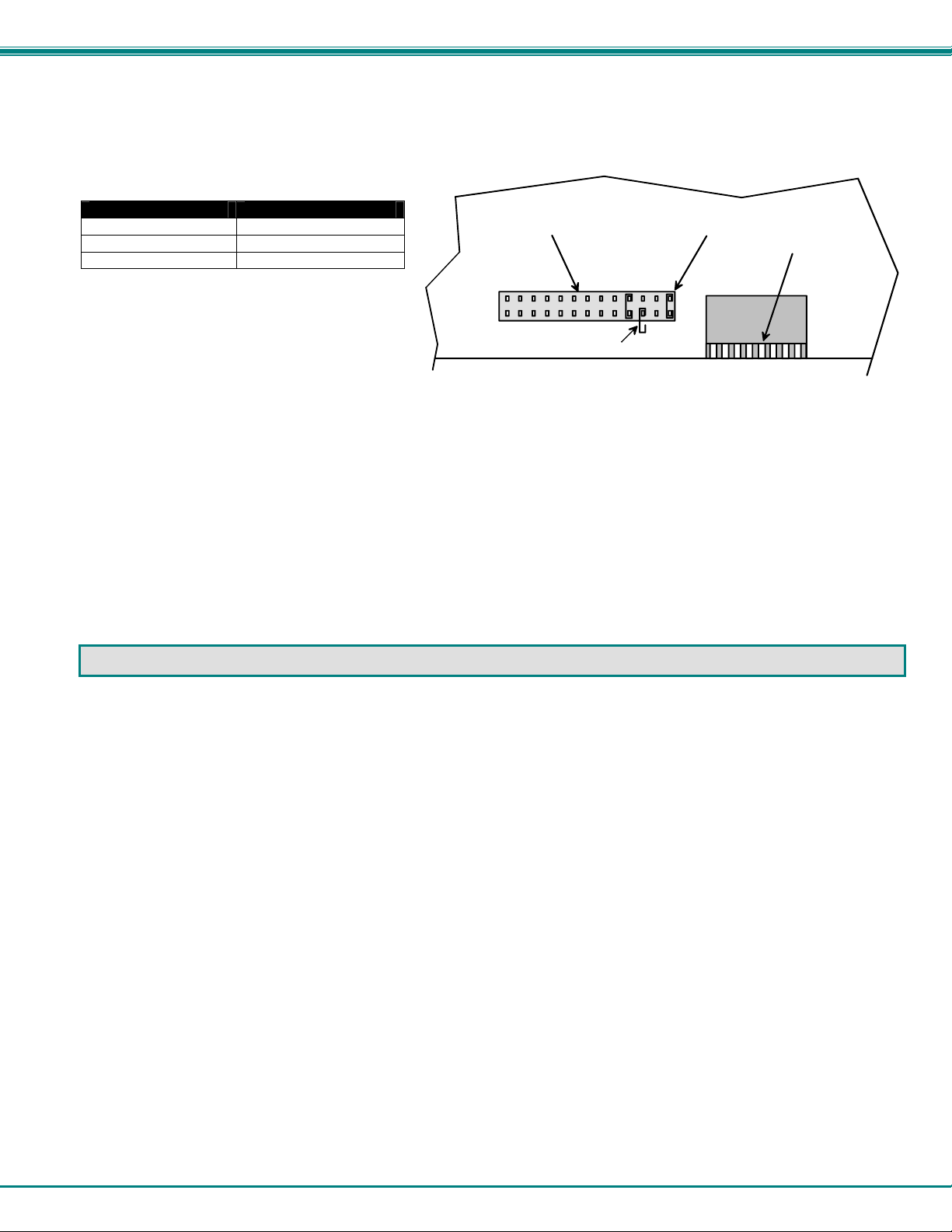
Configuring The Jumper Block
Once the jumper block is exposed, apply a jumper across the appropriate pins to disable the desired mode(s) according to
the chart below.
Pin Designation Mode
KCMD Command Mode*
BRDC Broadcast Mode
SCAN Scan Mode
*Note: Putting a jumper across pins KCMD to
disable Command Mode will also disable
JUMPER BLOCK
S
B
C
R
A
D
N
C
Broadcast and Scan Modes.
Drawing shows jumper across SCAN pins, disabling Scan Mode.
Broadcast Mode is still enabled .
JUMPER (unused)
Figure 20- Place jumpers according to desired functionality
Once the desired jumpers are in place, reverse the disassembly process to re-assemble the KEEMUX. Be particularly
careful about connecting the ribbons back to the headers they were removed from and to fully insert the ribbons into the hea ders.
Note: The text on the video ribbons should face the right-hand side of the case after insertion. Do not turn the power ON until all
connections have been completely and properly made and the unit has been properly re-assembled.
If the unit has an LCD
this jumper will be here.
L
K
C
C
D
M
E
D
DIP SWITCHE S
DDC SUPPORT
(Optional)
DDC information allows the CPU to automatically select the optimal resolution for the monitor by receiving, at power up,
information from the monitor concerning its resolution specifications.
When DDC Support is installed, the DDC information is acquired from the monitor by the KEEMUX when the KEEMUX is
powered-up. A monitor with DDC support must be connected to MONITOR for this to occur. The DDC information will be
made available at every CPU port.
The DDC information can also be acquired by pressing the DDC button located on the front of the switch (when supported). This
button allows the monitor configuration to be changed without powering down t he switch.
Note: In order for the CPU to correctly receive the DDC information from the switch at boot-up, the switch must be
powered up before all attached CPUs.
23
Page 28

NTI KEEMUX Series PS/2 KVM Switch
AUDIO SUPPORT
(Optional)
Audio support provides the following additional features:
• Audio signals from the same CPU that keyboard, mouse, and video signals are from can be received by the user.
• Audio inputs accept any standard line level audio (1Vrms or 2.5Vp-p).
• Audio outputs are capable of driving an 8 Ohm speaker load with 200mW of continuous RMS power.
Audio signals are switched along with the keyboard, mouse and video signals using the buttons on the KEEMUX switch.
5VDC
2A
-
Figure 21- Control CPU audio with KEEMUX-P4-A
Rear View of KEEMUX-P4-A
AUD
AUD 1 AUD 4 AUD 3
AUD 2
NTI
+
1275 Danner Dr
Aurora, OH 44202
www.nti1.com
Tel:330-562-7070
Fax:330-562-1999
R
OUT
C
C
P
P
U
U
3
4
CPU 2CPU 3CPU 4
V
V
I
D
E
O
3
C
P
U
1
PS/2 DEVICES
V
I
D
E
O
2
Mouse
Keyboard
Daisy Daisy
Out In
I
D
E
O
4
C
P
U
2
CPU 1
M
V
O
I
N
D
I
E
T
O
O
1
R
DUAL VIDEO SUPPORT
(Optional- 4 port models only)
Dual Video support enables CPUs with two video outputs to be connected to the KEEMUX switch and two user monitors to be
connected to view both sets of video signals. Both monitors must be of the type VGA multi-scan.
-
5VDC
2A
Figure 22- Connections for video cables on the KEEMUX-P4-DV
Rear View of KEEMUX-P4-DV
M
V
V
V
V
I
D
E
O
4
+
I
D
E
O
3
NTI
1275 Danner Dr
Aurora, O H 44202
www.nti1.com
Tel:330-562- 7070
Fax:330-562- 1999
I
D
E
O
2
R
O
I
N
I
D
T
E
O
O
R
2
1
C
C
P
P
U
U
3
4
CPU 2CPU 3CPU 4
V
I
D
E
O
4
C
P
U
2
CPU 1
I
D
E
O
3
I
D
E
O
2
C
P
U
1
PS/2 DEVICES
Keyboard
I
D
E
O
1
Mouse
Daisy Daisy
Ou t In
O
N
I
T
O
R
1
M
V
V
V
24
Page 29

NTI KEEMUX Series PS/2 KVM Switch
TROUBLESHOOTING
If the KEEMUX is not working properly, please look for a solution in the list below:
PROBLEM:
SOLUTION:
PROBLEM:
SOLUTION:
PROBLEM:
SOLUTION:
PROBLEM:
SOLUTION:
PROBLEM:
SOLUTION:
If a solution was not found in the list above, answers may be found in the Frequently Ask Questions (FAQs) section of our
website at http://www.networktechinc.com
happy to assist in any way we can.
SERIAL NO.: _____
DATE: ____________
INSPECTED BY: _____
-O OPTION -RS OPTION -A OPTION -DV OPTION
Keyboard Errors
Check cable connections on each CPU and the switch.
No Video
Check cable connections on each CPU and the switch. Verify that keyboard, video, and mouse connect from
each CPU to matching ports. After reconnecting, the CPU may need to be re-booted in order to sense the
monitor connection.
No Mouse Movement
Check cable connections on each CPU and the switch. Verify that keyboard, video, and mouse connect from
each CPU to matching ports. Verify that the mouse driver was loaded.
No Keyboard Activity after running shutdown program on IBM PowerServer 220
1. Select a different port from the front panel buttons.
2. Turn power OFF to PowerServer 220.
(either step above will enable keyboard)
Monitor shuts down while working with OSD menu
Disengage or increase time setting of CPU’s monitor “sleep” mode from the BIOS and/or control panel display
settings. (The CPU does not sense activity while in the OSD menu )
or call us directly at (800) 742-8324 (800-RGB-TECH) or (330) 562-7070 and we will be
KEEMUX-P4
KEEMUX-P8
KEEMUX-P12
KEEMUX-P16
KEEMUX-P20
KEEMUX-P24
KEEMUX-P32
Man077 Rev 7/1/07
25
 Loading...