

Page 1
ENVIROMUX
®
Series
IPDU-Sx
Secure Remote Power Reboot Switch
Installation and Operation Manual
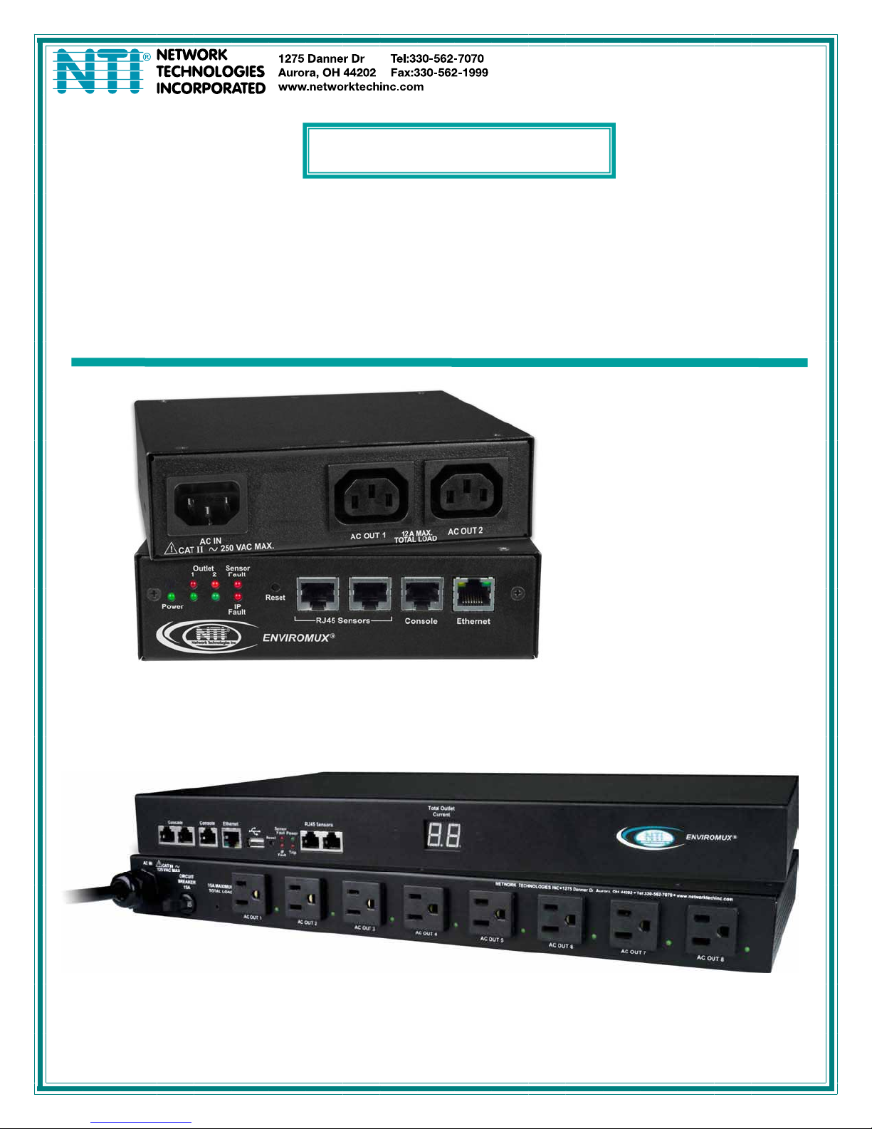
Front and Rear View of IPDU-S2
Front and Rear View of IPDU-S8-P15
MAN119 Rev Date 4/22/14
Page 2

TRADEMARK
ENVIROMUX is a registered trademark of Network Technologies Inc in the U.S. and other countries.
COPYRIGHT
Copyright © 2009, 2014 by Network Technologies Inc. All rights reserved. No part of this publication may be reproduced, stored
in a retrieval system, or transmitted, in any form or by any means, electronic, mechanical, photocopying, recording, or otherwise,
without the prior written consent of Network Technologies Inc, 1275 Danner Drive, Aurora, Ohio 44202.
CHANGES
The material in this guide is for information only and is subject to change without notice. Network Technologies Inc reserves the
right to make changes in the product design without reservation and without notification to its users.
FIRMWARE VERSION
IPDU-S2 Version 1.5
IPDU-S4/8 Version 1.6
This product contains software licensed under the GNU Public License version 2 and other open source licenses.
( http://www.gnu.org/copyleft/gpl.html
You may obtain the complete open-source code free of charge from Network T echnolog ies Inc (send email to techconsult@ntigo.com) for more information.
)
i
Page 3

TABLE OF CONTENTS
IPDU-Sx...........................................................................................................................................................................1
Secure Remote Power Reboot Switch........................................................................................................................1
Installation and Operation Manual...............................................................................................................................1
Introduction......................................................................................................................................................................1
Materials..........................................................................................................................................................................2
Supported Web Browsers ...............................................................................................................................................2
Features and Functions...................................................................................................................................................3
Installation .......................................................................................................................................................................5
Connect AC Power Cables..........................................................................................................................................5
Ethernet Connection....................................................................................................................................................5
Terminal Connection for RS232..................................................................................................................................6
Sensor Attachment......................................................................................................................................................6
Front Panel LEDs Indicate Status ...............................................................................................................................7
Cascaded Installation via RS485 Connection .............................................................................................................8
GSM Modem Connection ............................................................................................................................................8
Rack Mounting Instructions .........................................................................................................................................9
Overview........................................................................................................................................................................10
Administration.........................................................................................................................................................10
General Functions...................................................................................................................................................10
Security...................................................................................................................................................................12
Device Discovery Tool...................................................................................................................................................13
How to Use the Device Discovery Tool.....................................................................................................................13
Operation via Web Interface..........................................................................................................................................14
Log In and Enter Password .......................................................................................................................................14
Monitoring..................................................................................................................................................................15
Configure a Power Outlet .......................................................................................................................................17
Line Monitor............................................................................................................................................................20
Monitor and Configure Sensors..............................................................................................................................22
Monitor IP Devices..................................................................................................................................................25
Monitor Events........................................................................................................................................................28
Administration............................................................................................................................................................30
System Configuration .............................................................................................................................................30
Enterprise Configuration.........................................................................................................................................32
Network Configuration............................................................................................................................................33
Cascade Configuration...........................................................................................................................................38
User Configuration..................................................................................................................................................43
Security...................................................................................................................................................................47
System Information.................................................................................................................................................50
Update Firmware ....................................................................................................................................................51
Reboot the System .................................................................................................................................................52
Log.............................................................................................................................................................................53
View Event Log.......................................................................................................................................................53
View Data Log.........................................................................................................................................................54
ii
Page 4

Log Settings............................................................................................................................................................54
Support ......................................................................................................................................................................57
Logout........................................................................................................................................................................57
Operation via Text Menu- IPDU-Sx...............................................................................................................................58
Connection Via Console Port ....................................................................................................................................58
Connect to IPDU-Sx from Command Line.................................................................................................................59
Connect Via Telnet .................................................................................................................................................59
Connect Via SSH....................................................................................................................................................59
Using the Text Menu..................................................................................................................................................61
Monitoring...............................................................................................................................................................61
System Configuration .............................................................................................................................................77
Enterprise Configuration.........................................................................................................................................79
Network Configuration............................................................................................................................................79
Cascade Configuration...........................................................................................................................................85
User Configuration..................................................................................................................................................90
Security Configuration ............................................................................................................................................94
Event and Data Logs..............................................................................................................................................97
System Information...............................................................................................................................................100
Reboot ..................................................................................................................................................................101
Text Menu for Non-Administrative Users.................................................................................................................102
Monitoring.............................................................................................................................................................102
User Accessible Settings......................................................................................................................................104
Reset Button................................................................................................................................................................107
Circuit Breaker.............................................................................................................................................................107
USB Port......................................................................................................................................................................107
Wiring Methods ...........................................................................................................................................................108
PC-to IPDU-Sx Crossover Cable.............................................................................................................................108
RS485 Sensor Cable...............................................................................................................................................108
Technical Specifications..............................................................................................................................................109
Troubleshooting...........................................................................................................................................................110
Index............................................................................................................................................................................111
Warranty Information...................................................................................................................................................112
Figure 1- Connect power cords..........................................................................................................................................................5
Figure 2- Connect IPDU-S2 to the Ethernet.......................................................................................................................................5
Figure 3- Connect IPDU-S2 to local terminal.....................................................................................................................................6
Figure 4- Connect sensors for environmental monitoring..................................................................................................................6
Figure 5- LEDs on front of IPDU-S2 ..................................................................................................................................................7
Figure 6- LEDs on front of IPDU-S4/S8.............................................................................................................................................7
Figure 7- Cascade installation- RS485 Connection...........................................................................................................................8
Figure 8- Connect a GSM modem.....................................................................................................................................................8
Figure 9- Secure rack mount ears to IPDU-Sx...................................................................................................................................9
Figure 10- Secure IPDU-Sx to rack ...................................................................................................................................................9
Figure 11- Device Discovery Tool....................................................................................................................................................13
Figure 12- Login prompt to access web interface............................................................................................................................14
iii
TABLE OF FIGURES
Page 5

Figure 13- Summary page...............................................................................................................................................................15
Figure 14- Summary page and the Monitoring menu.......................................................................................................................16
Figure 15- Status page for a power outlet........................................................................................................................................16
Figure 16- Power Outlet Configuration page....................................................................................................................................17
Figure 17- More settings for Power Outlet Configuration.................................................................................................................18
Figure 18- Line Monitor Categories .................................................................................................................................................20
Figure 19- Configuration Categories................................................................................................................................................21
Figure 20- Sensor Status page........................................................................................................................................................22
Figure 21- Sensor Configuration page.............................................................................................................................................22
Figure 22- Sensor Configuration- full view of settings......................................................................................................................23
Figure 23- IP Devices listing-none monitored yet ............................................................................................................................25
Figure 24- Add New IP Device page................................................................................................................................................25
Figure 25- IP Device Configuration page.........................................................................................................................................26
Figure 26- Power Outlet Association for IP Device..........................................................................................................................27
Figure 27- IP Device list with new devices added............................................................................................................................27
Figure 28- IP Device Status page....................................................................................................................................................27
Figure 29- Event Monitoring.............................................................................................................................................................28
Figure 30- Add New Event...............................................................................................................................................................28
Figure 31- Configure New Event......................................................................................................................................................28
Figure 32- List of Configured Event.................................................................................................................................................29
Figure 33- Adjust settings for events ...............................................................................................................................................29
Figure 34- System Configuration page ............................................................................................................................................30
Figure 35- Enterprise Configuration.................................................................................................................................................32
Figure 36- Network Configuration page...........................................................................................................................................33
Figure 37- Network Configuration- more settings ............................................................................................................................34
Figure 38- IP Aliases........................................................................................................................................................................36
Figure 39- Setup SNMP to control output relays..............................................................................................................................37
Figure 40- Cascading- Set the configuration type............................................................................................................................38
Figure 41- Configure as RS485 Slave .............................................................................................................................................39
Figure 42- Configure as Ethernet Slave...........................................................................................................................................39
Figure 43- Configure as RS485 Master ...........................................................................................................................................40
Figure 44- Configure as Ethernet Master.........................................................................................................................................41
Figure 45- Cascade Notification Settings.........................................................................................................................................42
Figure 46- Users page.....................................................................................................................................................................43
Figure 47- Configure Users page.....................................................................................................................................................43
Figure 48- Configure User- more options.........................................................................................................................................44
Figure 49-Summary page for User without Admin privileges...........................................................................................................46
Figure 50- Security Configuration page ...........................................................................................................................................47
Figure 51- Security Configuration-X509 Certificate and Login Alerts...............................................................................................48
Figure 52- Security Configuration- IP Filtering Rules.......................................................................................................................49
Figure 53- System Information page................................................................................................................................................50
Figure 54- Update Firmware page...................................................................................................................................................51
Figure 55- Reboot System page......................................................................................................................................................52
Figure 56- System is rebooting........................................................................................................................................................52
Figure 57- Event Log page ..............................................................................................................................................................53
Figure 58- Data Log page................................................................................................................................................................54
Figure 59- Log Settings page...........................................................................................................................................................55
Figure 60- Log to USB Flash Settings..............................................................................................................................................55
Figure 61- Enable USB Port ............................................................................................................................................................56
Figure 62- Support...........................................................................................................................................................................57
Figure 63- Logout ............................................................................................................................................................................57
iv
Page 6

Figure 64- Text Menu Login screen.................................................................................................................................................58
Figure 65- Text Menu- Administrator Main Menu.............................................................................................................................59
Figure 66- Text Menu- Main Administrator Menu in IPDU-S4/-S8...................................................................................................60
Figure 67- Text Menu- User Main Menu..........................................................................................................................................60
Figure 68- Text Menu-Monitoring Menu...........................................................................................................................................61
Figure 69- Text Menu-Power Outlet Status......................................................................................................................................62
Figure 70- Text Menu-Sensor Status...............................................................................................................................................62
Figure 71- Text Menu- Line Monitor Parameters.............................................................................................................................63
Figure 72- Text Menu-View IP Devices............................................................................................................................................63
Figure 73- Text Menu-Configure Power Outlets ..............................................................................................................................64
Figure 74- Text Menu-Power Outlet menu.......................................................................................................................................64
Figure 75- Text Menu-Power Outlet Settings...................................................................................................................................65
Figure 76- Text Menu-Power Outlet Notification Settings................................................................................................................65
Figure 77- Text Menu-Power Outlet Operation Settings..................................................................................................................66
Figure 78- Text Menu-Configure Sensors list ..................................................................................................................................67
Figure 79- Text Menu-Configuration Menu for Sensor.....................................................................................................................68
Figure 80- Text Menu-Sensor Settings............................................................................................................................................68
Figure 81- Text Menu-Sensor Alert Settings....................................................................................................................................69
Figure 82- Text Menu-Sensor Data Logging....................................................................................................................................71
Figure 83- Text Menu- Sensor Power Outlet Association................................................................................................................71
Figure 84- Configure Line Monitor Parameters................................................................................................................................72
Figure 85- Configuration Menus ......................................................................................................................................................72
Figure 86- Text Menu-Configure IP Devices List.............................................................................................................................73
Figure 87- Text menu-Configuration Menu for IP Devices...............................................................................................................73
Figure 88-Text Menu-IP Device Settings.........................................................................................................................................74
Figure 89- Text Menu-IP Device Alert Settings................................................................................................................................75
Figure 90- Text Menu-IP Device Data Logging................................................................................................................................76
Figure 91- Text Menu-IP Device Power Outlet Association.............................................................................................................76
Figure 92- Text Menu- System Configuration..................................................................................................................................77
Figure 93- Text Menu-Time Settings menu......................................................................................................................................77
Figure 94- Text Menu-Restore Default Settings...............................................................................................................................78
Figure 95- Text Menu-Enterprise Configuration...............................................................................................................................79
Figure 96- Text Menu-Network Configuration..................................................................................................................................79
Figure 97- Text Menu-IP Settings Menu..........................................................................................................................................80
Figure 98- Text Menu-SMTP Server Settings..................................................................................................................................81
Figure 99- Text Menu-SNMP Server Settings..................................................................................................................................82
Figure 100- Text Menu-Misc. Service Settings menu......................................................................................................................83
Figure 101- Text Menu- IP Alias Settings ........................................................................................................................................84
Figure 102- Text Menu- Type Setting for Cascading .......................................................................................................................85
Figure 103- Text Menu- Unit RS485 Address..................................................................................................................................86
Figure 104- Text Menu- Type is Ethernet Slave ..............................................................................................................................86
Figure 105- Text Menu- RS485 Master's slave list ..........................................................................................................................87
Figure 106- Text Menu- Edit RS485 Slave Address ........................................................................................................................87
Figure 107- Text Menu- Ethernet Master's slave list........................................................................................................................88
Figure 108-Text Menu- Edit Ethernet Slave Address .......................................................................................................................88
Figure 109- Text Menu-Cascade Notification Settings.....................................................................................................................89
Figure 110- Cascade Notification Configuration ..............................................................................................................................89
Figure 111- Text Menu-User Configuration......................................................................................................................................90
Figure 112- Text Menu-Confirm to add new user ............................................................................................................................90
Figure 113- Text Menu-Configuration List for User..........................................................................................................................91
Figure 114- Text Menu-User Account Settings................................................................................................................................91
v
Page 7

Figure 115- Text Menu-User Contact Settings.................................................................................................................................92
Figure 116- Text Menu-User Activity Schedule................................................................................................................................93
Figure 117- Text Menu-Security Configuration ................................................................................................................................94
Figure 118- Text Menu-Authentication Settings ...............................................................................................................................94
Figure 119- Text Menu-IP Filtering..................................................................................................................................................95
Figure 120- Text Menu-Configure IP Filter rule................................................................................................................................96
Figure 121- Text Menu-Event & Data Logs......................................................................................................................................97
Figure 122- Text Menu-View Event Log...........................................................................................................................................97
Figure 123- Text Menu-View Data Log............................................................................................................................................98
Figure 124- Text Menu-Event Log Settings .....................................................................................................................................99
Figure 125-Text Menu-Data Log Settings........................................................................................................................................99
Figure 126- Enable Log to USB.....................................................................................................................................................100
Figure 127-Text Menu-System Information....................................................................................................................................100
Figure 128- Text Menu-Reboot the IPDU-S2.................................................................................................................................101
Figure 129- Text Menu-User Main Menu.......................................................................................................................................102
Figure 130-Text Menu-User Monitoring Menu ...............................................................................................................................102
Figure 131- Text Menu-User accessible status menus..................................................................................................................103
Figure 132- Text Menu-User Accessible Settings..........................................................................................................................104
Figure 133- Text Menu-User Account Settings..............................................................................................................................104
Figure 134- Text Menu-User Contact Settings...............................................................................................................................105
Figure 135- Text Menu-User Activity Schedule..............................................................................................................................106
Figure 136- Location of Reset button.............................................................................................................................................107
Figure 137- Circuit Breaker Protection...........................................................................................................................................107
Figure 138- USB Flash Drive port..................................................................................................................................................107
vi
Page 8

NTI Secure Remote Power Reboot Switch
INTRODUCTION
The ENVIROMUX® IPDU-Sx Secure Remote Power Reboot Switch allows you to remotely reboot and control power (ON/OFF) or
to schedule periodic power cycles to servers or other powered devices from any location via secure web interface, RS232, SSH,
or Telnet.
Models Include:
Model Decription Model Decription
IPDU-S2
IPDU-S4-P10
IPDU-S4-P15
-P10 models include IEC 320-C13 outlets
-P15 models include NEMA 5-15R outlets
Features:
2-Outlet
4-Outlet, for Euro/UK
4-Outlet, for US/Canada
• Supports Power ON or OFF in addition to Reboot.
• Three operating modes for power control:
o Manual — user can power cycle an outlet for a configured time sequence or power an outlet ON or OFF.
o Periodic — set a date, time, and duration of the power cycle. Power cycles can also be scheduled as recurring
daily, weekly, or monthly.
o Associated — power ON or OFF a device when a sensor exceeds a user-defined threshold, or power cycle if an
IP device is unresponsive.
IPDU-S8-P10
IPDU-S8-P15
8-Outlet, for Euro/UK
8-Outlet, for US/Canada
• Security: HTTPS, SSHv2, SSLv3, IP Filtering, LDAPv3, AES 256-bit encryption, 16-character username/password
authentication, user account restricted access rights.
• Power Up Sequencing limits in-rush current.
• Monitor (ping) up to 8 IP network devices.
o Configure the timeout and number of retries to classify a device as unresponsive.
o Power cycle associated power outlets if devices are not responding.
o Alerts are sent if devices are not responding.
• Outlets can be individually named (up to 80 characters).
• Monitor environmental conditions.
o Supports two sensors, including: temperature, humidity, and water detection.
o When a sensor goes out of range of a configurable threshold, the system will notify you via email, syslog, LEDs,
web page, and network management (SNMP).
o Powers up or down devices when sensors go out of range of user-defined thresholds.
• Operates on a hardened Linux system.
• Firmware upgradeable "in-field" through console port or Ethernet.
• Up to 17 units can be cascaded into a system of up to136 outlets controlled either locally via RS485 or remotely via web
interface (models IPDU-S4 and IPDU-S8 only)
• Line Monitoring (IPDU-S4 and IPDU-S8 only)
o Monitor outlet voltage
o Monitor outlet current
o Monitor outlet frequency
o Monitor circuit breaker status
• Configurable events (IPDU can send alerts or control outlets as reaction to specific sensor readings) (models IPDU-S4
and IPDU-S8 only)
1
Page 9
NTI Secure Remote Power Reboot Switch
MATERIALS
Materials supplied with this kit:
• NTI IPDU-Sx Secure Remote Power Reboot Switch
• 1- IEC320-C13 Line cord, country specific (PS4162) (IPDU-S2 and IPDU-S4/8-P10 only)
• 1- IEC320-C14 Output cord (PS4163) (IPDU-S2 and IPDU-S4/S8-P10 only)
• 1- DB9 Female-to-RJ45 Female adapter (CT6182)
• 1- 5 foot RJ45-to-RJ45 CAT5 patch cable (CB4352)
• CD containing a pdf of this manual, a SNMP MIB file (2-outlet version and 4/8-outlet version), and the NTI Discovery Tool
• Rackmount Kit as detailed in the chart below:
Model Mounting Brackets
(X2)
IPDU-S2 MP4040 HW5133 HW5118 HW5124
IPDU-S4-Pxx MP4212 HW5133 HW5118 HW5124
IPDU-S8-Pxx MP4210 HW5133 HW5118 HW5124
Screws
(X6)
Cage Nuts
(x4)
#10-32 Screws
(x4)
SUPPORTED WEB BROWSERS
Most modern web browsers should be supported. The following browsers have been tested:
• Microsoft Internet Explorer 6.0 or higher
• Netscape 7.2 or higher
• Mozilla FireFox 1.5 or higher
• Opera 9.0
• Google Chrome
• Safari 4.0 or higher for MAC and PC
2
Page 10
NTI Secure Remote Power Reboot Switch
FEATURES AND FUNCTIONS
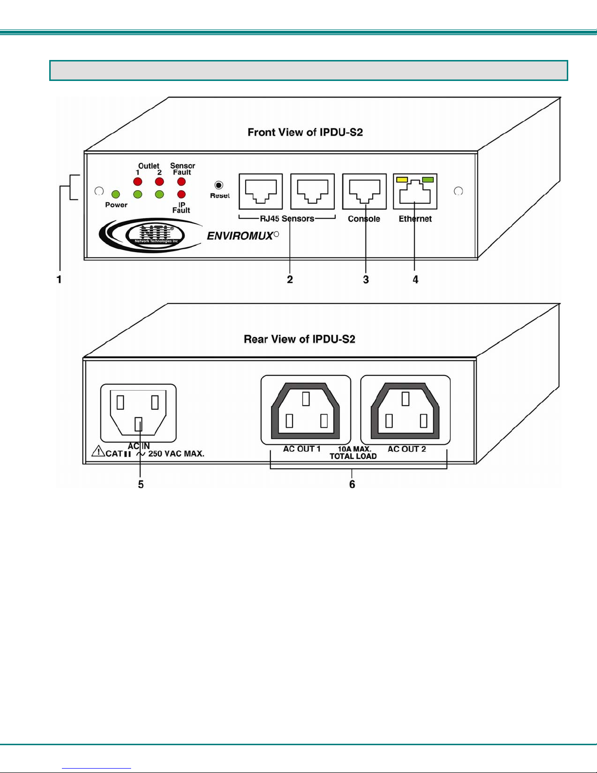
IPDU-S2
1. LED Indicators
• "POWER" (green) — indicates device is powered
• "OUTLET" (green / red) — outlet is ON (green) or OFF (red)
• "SENSOR FAULT" (red) — illuminates if a sensor goes out of range of a configurable threshold
• "IP FAULT" (red) — illuminates if an IP device is unresponsive
2. RJ45 Sensors- RJ45 female- for attachment of temperature, humidity, or liquid detection sensors
3. Console- RJ45 female- for connection to a terminal for local control
4. Ethernet- RJ45 female with LED indicators- for connection to an Ethernet for remote multi-user control and monitoring
Yellow LED- indicates 100Base-T activity when illuminated, 10Base-T activity when dark
Green LED – illuminated when Ethernet link is present, strobing indicates activity on the Ethernet port
5. AC IN- IEC320-C14 socket- for connection of AC line cord
6. AC OUT 1 & 2- IEC320-C13 socket- for connection of load device cables
3
Page 11
NTI Secure Remote Power Reboot Switch
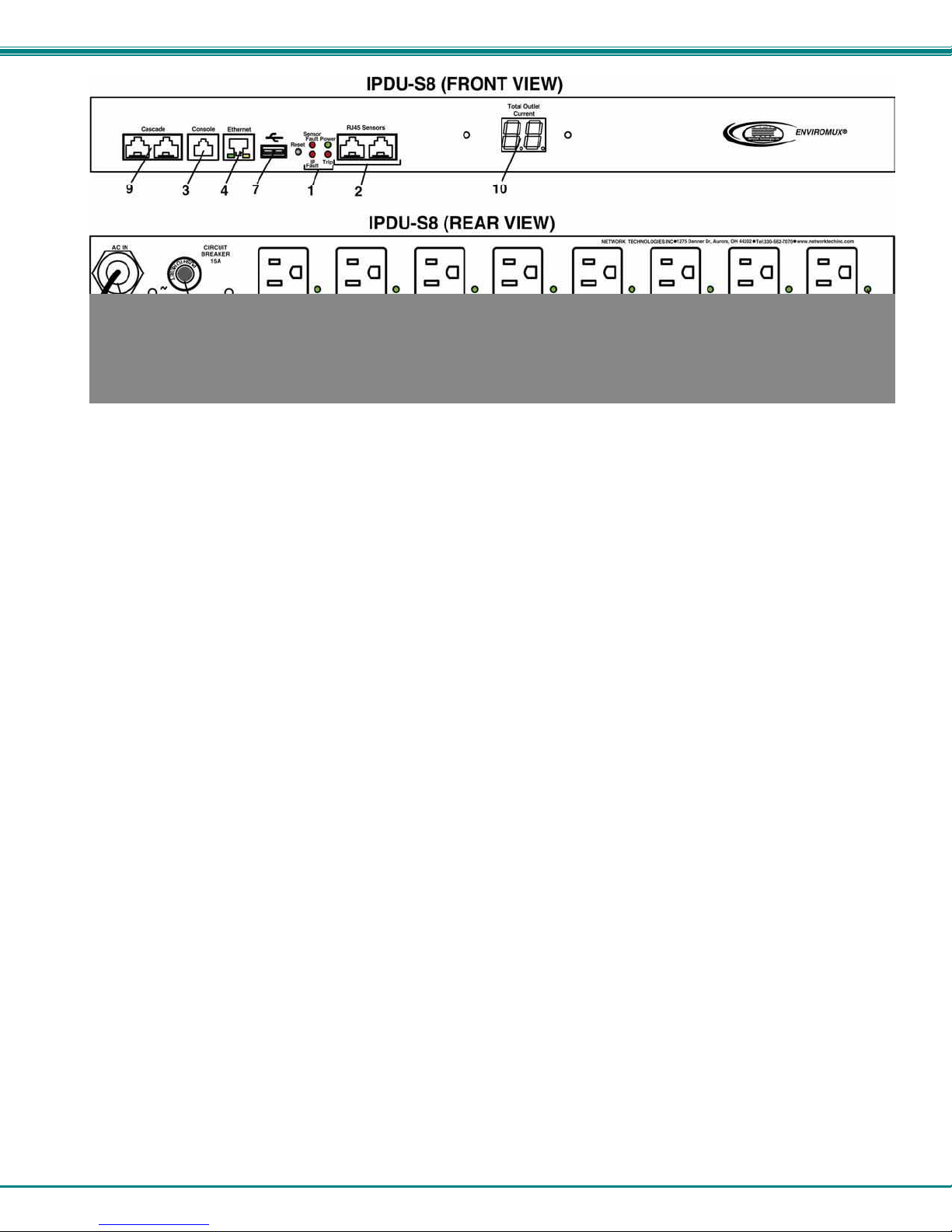
IPDU-S4 / IPDU-S8
1. LED Indicators
• "POWER" (green) — indicates device is powered
• "SENSOR FAULT" (red) — illuminates if a sensor goes out of range of a configurable threshold
• "IP FAULT" (red) — illuminates if an IP device is unresponsive
• “TRIP” (red) -illuminates if the circuit breaker on the rear of the unit trips OFF
2. RJ45 Sensors- RJ45 female- for attachment of temperature, humidity, or liquid detection sensors
3. Console- RJ45 female- for connection to a terminal for local control
4. Ethernet- RJ45 female with LED indicators- for connection to an Ethernet for remote multi-user control and monitoring
Yellow LED- indicates 100Base-T activity when illuminated, 10Base-T activity when dark
Green LED – illuminated when Ethernet link is present, strobing indicates activity on the Ethernet port
5. AC IN- 120V AC line cord (15A maximum load (–P15 models only)
The IPDU-S4/S8-P10 has a IEC320-C14 socket (item 5 on the IPDU-S2)
6. AC OUT 1-8- NEMA 5-15R outlets (-P15 models) or IEC 320-C13 outlets (-P10 models) - for connection of load device cables
6a. Green LED - illuminates when associated outlet power is ON (1 per outlet)
7. USB- USB Type A port- for connection of a GSM modem for SMS communication and/or flash drive (USB 2.0 Full Speed
supported) for logging data
8. Circuit Breaker- 15A Circuit breaker for protection of the devices powered by the IPDU-Sx
9. Cascade- RJ45 Female- for cascading multiple IPDU-S4 and IPDU-S8 units
10. LED Display- for displaying the total AC current being supplied by the AC outlets on the IPDU-Sx
4
Page 12

NTI Secure Remote Power Reboot Switch
INSTALLATION
Connect AC Power Cables
The IPDU-Sx may be connected to a 100-240VAC power supply. A 120V power cord with NEMA 5-15 connector is provided for
connection to a power supply. The AC outlets (“AC OUT 1” and “AC OUT 2”) are rated for up to 10A @ 120/240VAC and the
combined maximum load cannot exceed 10A for IPDU-S2, IPDU-S4/S8-P10, or 15A for IPDU-S4/S8-P15.
Figure 1- Connect power cords
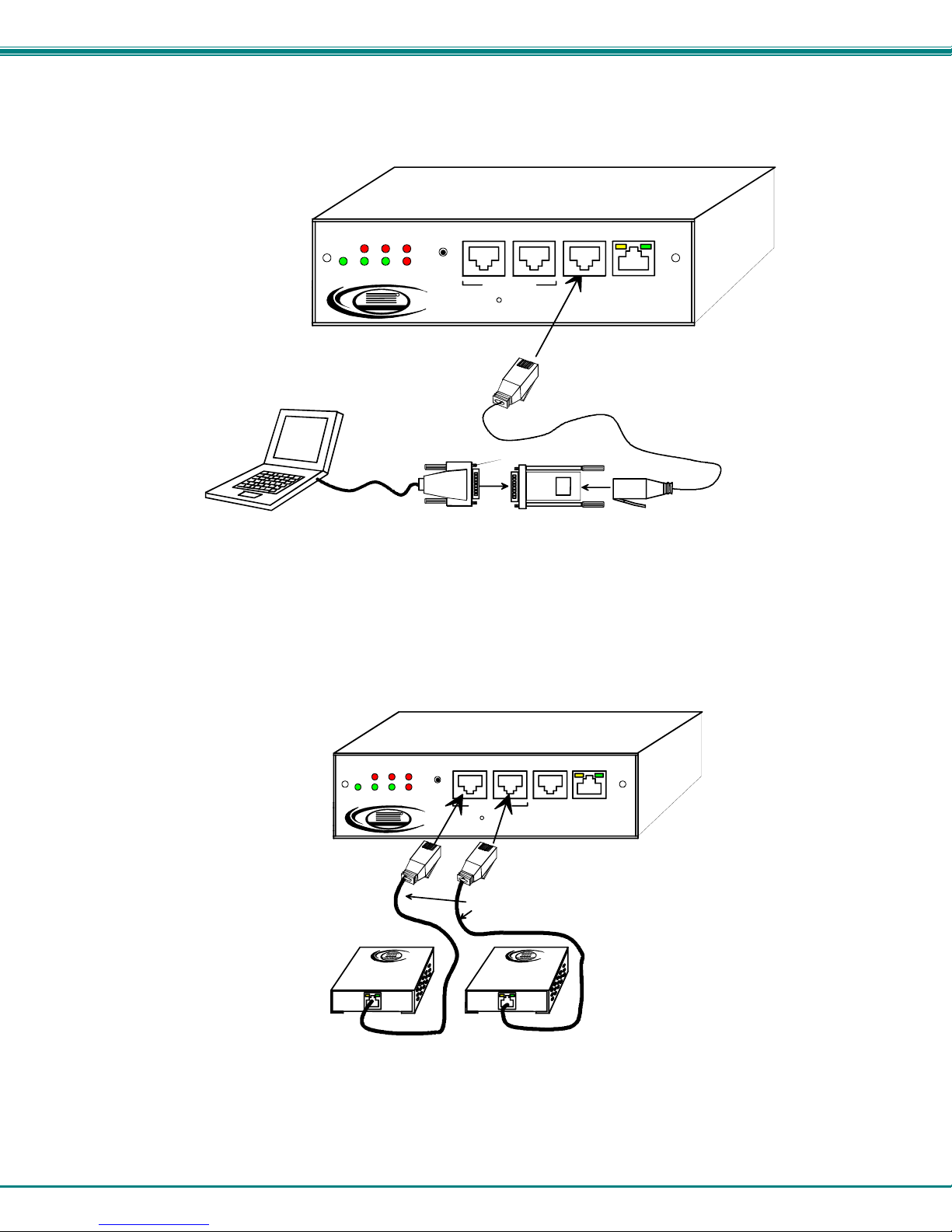
Ethernet Connection
Connect a CAT5 patch cable (RJ45 connectors on each end wired pin 1 to pin 1, pin 2 to pin 2 etc) from the local Ethernet
network connection to the connector on the IPDU-Sx marked "ETHERNET".
Outlet
Power
Ethernet
Figure 2- Connect IPDU-S2 to the Ethernet
Note: A direct Ethernet connection can be made with a PC using a crossover cable. For the pinout of this cable, see
page 108.
12
NTI
Network Tec hnolog ies Inc
Sensor
Fault
IP
Fault
R
Reset
RJ45 Sensors
ENVIROMUX
R
Console Ethernet
RJ45 male
connector
5
Page 13
NTI Secure Remote Power Reboot Switch
Terminal Connection for RS232
To make a direct serial connection to the IPDU-Sx from a terminal with HyperTerminal via RS232, an RJ45 female DCE port
labeled "Console" is provided. Connect a CAT5 patch cable (supplied) between the port lab eled “Console” and a PC with a
terminal program (e.g. HyperTerminal). An adapter (supplied) may need to be used to connect the patch cable to the PC.
Outlet
Power
Terminal
12
NTI
Network Technologies Inc
Sensor
Fault
IP
Fault
R
DB9 male
connector
Reset
ENVIROMUX
RJ45 Sensors
R
Console Ethernet
RJ45F-to-DB9F Adapter
(supplied)
CAT5 Patch Cable
Figure 3- Connect IPDU-S2 to local terminal
Sensor Attachment
The IPDU-Sx is capable of sensing and reporting readings taken from ENVIROMUX temperature (ENVIROMUX-STS), humidity
(ENVIROMUX-SHS), temperature/humidity (ENVIROMUX-STHS), wide range temperature/humidity (ENVIROMUX-STHS-99) and
liquid detection (ENVIROMUX-LDTx-y) sensors. Any of these can be connected to the “RJ45 Sensors” ports and used to
determine if connected devices should be powered ON or OFF based on readings taken. The maximum CAT5 cable length for
attachment of sensors is 1000 feet. For the cable pinout, see page 108.
Power
ENVIROMUX-STS
Temperature
Sensor
Outlet
12
NTI
Network Technologi es Inc
Sensor
Fault
IP
Fault
R
Reset
ENVIROMUX
RJ45 Sensors
R
Console Ethernet
CAT5 Cable- maximux 1000 feet
ENVIROMUX-SHS
Humidity
Sensor
Figure 4- Connect sensors for environmental monitoring
6
Page 14
NTI Secure Remote Power Reboot Switch
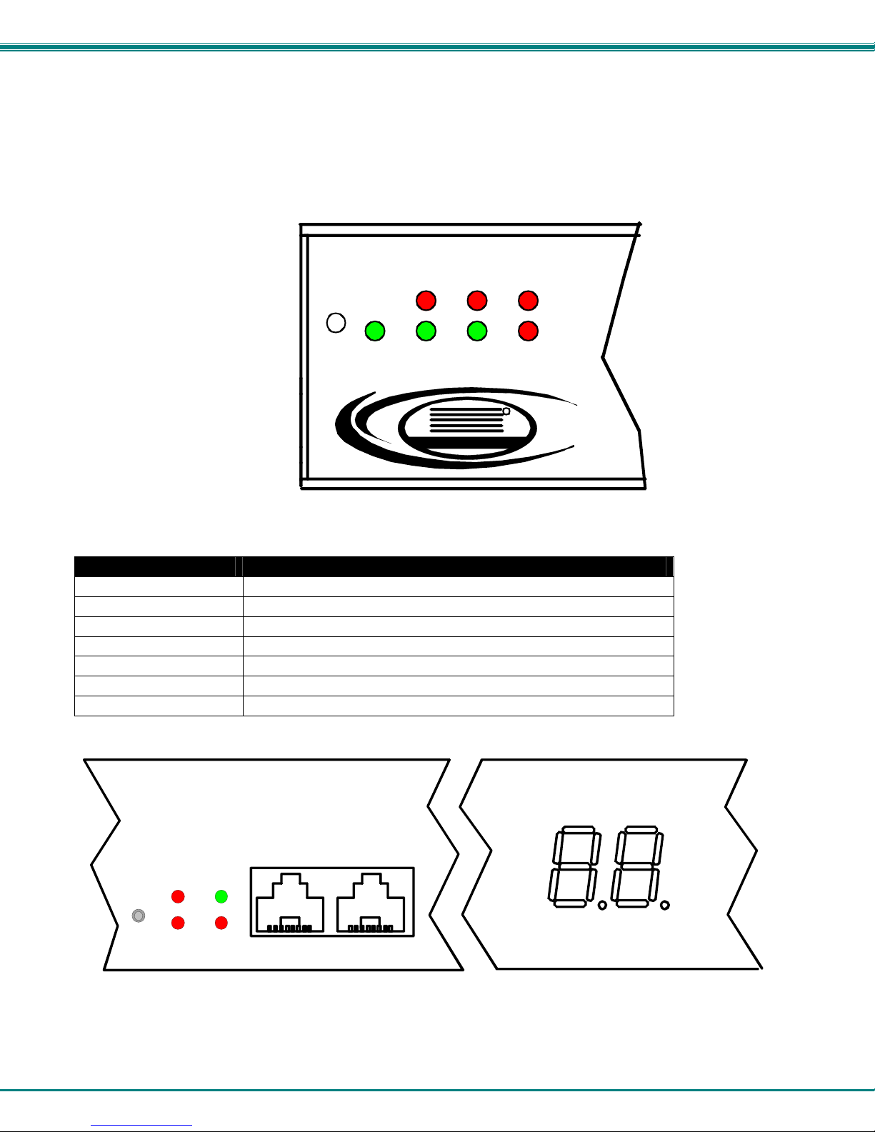
Front Panel LEDs Indicate Status
With proper connections made, the IPDU-Sx is now ready to use. With the power cord attached and plugged into an AC outlet,
the “Power” , “Outlet 1” and “Outlet 2” green LEDs should be illuminated on the front of the IPDU-S2. The table below describes
the function of each LED.
The IPDU-S4 and IPDU-S8 have a green LED adjacent to each outlet that will illuminate when power is ON to the outlet. (See
page 4.)
Power
Outlet
Sensor
12
Fault
R
NTI
Networ k Tech nolog ies In c
Fault
IP
Figure 5- LEDs on front of IPDU-S2
LED Description
Power-green Indicates the power status of the IPDU-Sx
Outlet 1 and 2-red Illuminates when the AC OUT (1 or 2) is powere d OFF
Outlet 1 and 2-green Illuminates when the AC OUT (1 or 2) is powered ON
Sensor Fault-red Illuminates if the connected sensors are outside of their thresholds
IP Fault- red Illuminates if there is an IP monitoring fault
Trip - red Illuminates if the breaker on the IPDU-S4/8 trips
Total Outlet Current Displays total current draw of all outlets (IPDU-S4/ -S8 only)
Reset
Sensor
Fault
IP
Fault
Power
Trip
RJ45 Sensors
Total Outlet
Current
Figure 6- LEDs on front of IPDU-S4/S8
7
Page 15
NTI Secure Remote Power Reboot Switch
Cascaded Installation via RS485 Connection
Two RJ45 ports are provided on the front of models IPDU-S4 and IPDU-S8. These are used when multiple units are connected
together (cascaded) and controlled as one system using the RS485 Connect method (see page 8). Cascading enables the
monitoring of all sensors and outlets from up to 17 IPDU-S4 or IPDU-S8 (or any combination of each model). For an RS485
Connect installation, connect a CAT5/5e/6 patch cable with RJ45 male connectors on each end (wired straight thru, pi n 1 to pin 1,
pin 2 to pin 2, etc.) between the “Cascade” ports as shown in the image below. The maximum distance from the Master to the last
Slave can be no more than 1000 feet. With this properly connected and configured (pages 38 and 85) , the user can monitor the
sensors and outlets of all systems from either a single connected terminal (page 6) or through the Web Interface.
Cascade Console
RJ45-male
connector
Ethernet
Reset
Sensor
Fault
Fault
IP
The maximum combined length of
cable from the Master unit to the
last Slave unit can be no more than
1000 feet.
IPDU-S8 MASTER with RS485 Slaves (FRONT VIEW)
Total Outlet
Current
RJ45-male
connector
Cascade Console
Cascade Console Ethernet
Cascade Console Ethernet
IPDU-S8 RS485 SLAVE (FRONT VIEW)
Ethernet
RJ45 Se nsors
Sensor
Fault
Power
Reset
IP
Trip
Fault
IPDU-S8 RS485 SLAVE (FRONT VIEW)
RJ45 Se nsors
Sensor
Fault
Power
Reset
IP
Trip
Fault
Total O utlet
Current
Total O utlet
Current
UP TO 16 UNITS CONNECTED
IPDU-S8 RS485 SLAVE (FRONT VIEW)
RJ45 Se nsors
Sensor
Fault
Power
Reset
IP
Trip
Fault
Total O utlet
Current
Power
Trip
RJ45 Sensors
NTI
Network Technolog ies Inc
Network Te chnol ogi es In c
Network Te chnol ogi es In c
Network Te chnol ogi es In c
R
R
NTI
R
NTI
R
NTI
ENVIROMUX
R
ENVIROMUX
R
ENVIROMUX
R
ENVIROMUX
R
Figure 7- Cascade installation- RS485 Connection
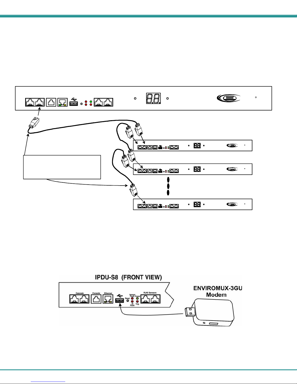
GSM Modem Connection
(IPDU-S4 and IPDU-S8 Models only)
If alert notifications via SMS to a cell phone are desired, a GSM modem can be connected to the USB port on the IPDU-S4 / -S8
models. With a GSM modem connected, a user can receive SMS alert messages directly on their cell phone. The external GSM
modem is powered by the USB port.
A GSM modem that has been tested and is confirmed to be compatible with the IPDU-S4/ -S8 is the iCON 452. To order this
modem, contact NTI and ask for the ENVIROMUX-3GU.
Figure 8- Connect a GSM modem
Note: The modem connected to the IPDU-Sx will send SMS messages only. No access to the IPDU-Sx is possible
through the modem.
8
Page 16
NTI Secure Remote Power Reboot Switch
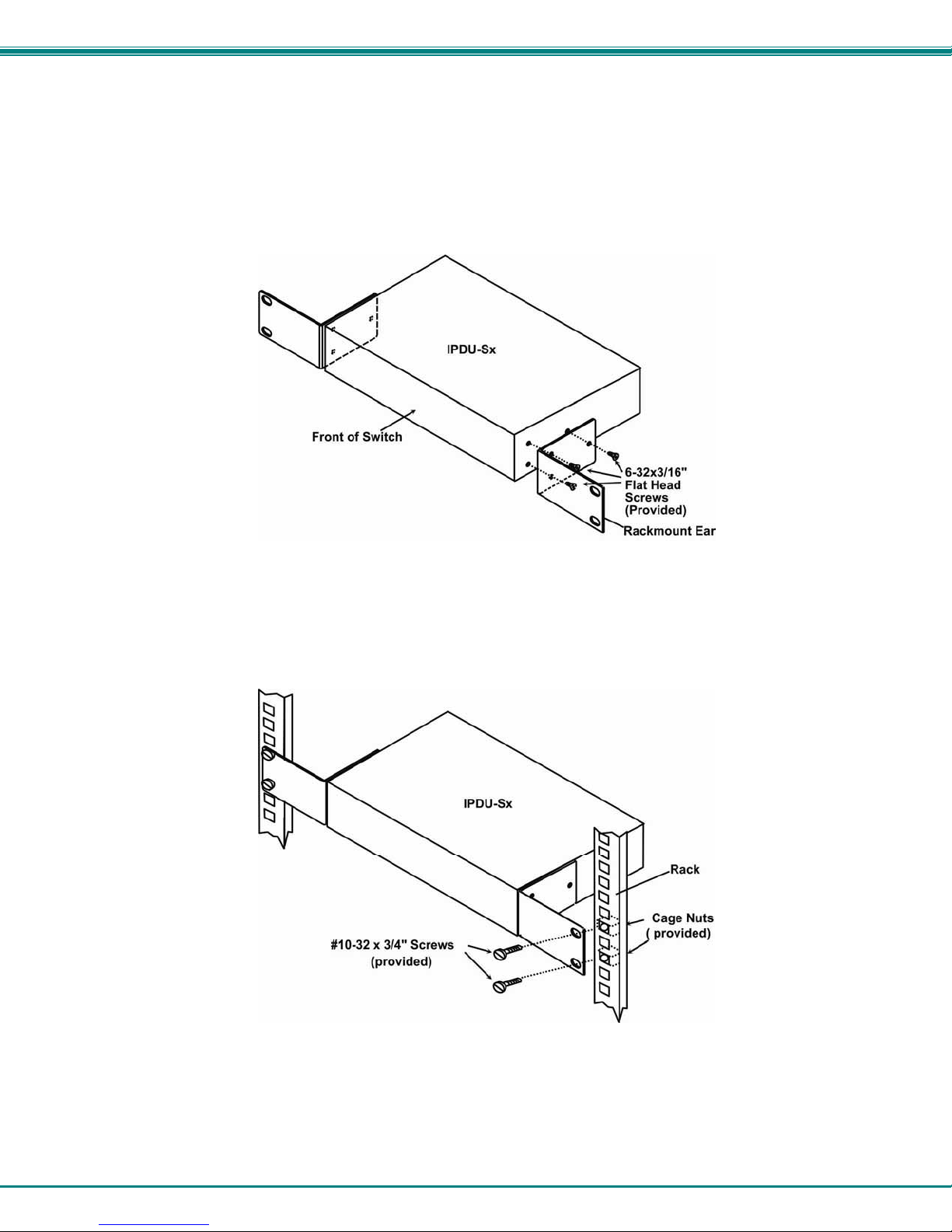
Rack Mounting Instructions
The IPDU-S4R and IPDU-S8 were designed to be mounted in a rack. They include a rack mount kit to make attachment easy.
1. Attach the ears to the IPDU-Sx using the #6-32x3/16" flat Phillips-head screws (6) provided as shown in the illustration
below.
2. The holes in the ears should line up with pre-threaded holes in the sides of the IPDU-Sx. Tighten the screws
securely.
Figure 9- Secure rack mount ears to IPDU-Sx
3. Install 4 cage nuts to the rack in locations that line up with the holes in the mounting ears on the IPDU-Sx.
4. Secure the IPDU-Sx to the rack using four #10-32x3/4” screws and cage nuts (provided). Be sure to tighten all mounting
screws securely.
Figure 10- Secure IPDU-Sx to rack
5. Attach all cables securely to the IPDU-Sx and where necessary supply adequate means of strain relief for
cables
9
Page 17

NTI Secure Remote Power Reboot Switch
OVERVIEW
Administration
The IPDU-Sx can be administered in any one of the following ways:
• Using a terminal program (e.g. HyperTerminal) via an RS232-Link, connected to Console Port.
• Using Telnet or SSH protocol via the Ethernet Port.
• Using the web interface (HTTP/HTTPS protocol) via the Ethernet Port.
The following administrative controls are available in the IPDU-Sx, thru the menu.
• View or modify the administrator & user parameters (passwords, outlet/sensor alert subscriptions, admin access, etc.)
• View or modify the network parameters (e.g. IP Address, Gateways, DNS, etc.)
• View and clear system event logs
• Clear, import, export and restore configuration parameters
• Firmware upgrades for the IPDU-Sx, thru Console port or over Ethernet
• View or modify sensor, IP device, and outlet configurations
Additional administrative controls available in IPDU-S4 and IPDU-S8 models include:
• Cascade configuration
• USB port enable/disable (for data logging)
• Three configurable IP aliases
General Functions
Manual Power Control
The user has the ability to power cycle either of the outlets by merely selecting the outlet and clicking on the appropriate action
from the web interface or text menu.
Periodic Power Control
The user can schedule power cycles for each of the outlets by setting the date and time of the reboot, the duration of the power
cycle (time ON or OFF), and whether the power cycle will be one-time, daily, weekly, or monthly. In the event that a user
schedules a monthly reboot on a date which not all months have, (e.g.. the 31
the final day of the months with fewer days.
Associated Power Control
The user can configure an outlet to power cycle when a sensor exceeds a certain threshold or when a n IP address is nonresponsive.
Sensor Alerts
A high and low threshold limit can be set for each temperature or humidity sensor. When a sensor takes a reading that is outside
a threshold, an alert notification is generated. The user can specify the frequency of alert notifications to match his or her
schedule. Also, there will be some hysteresis involved with alert notifications. This means if a sensor’s readings are moving in
and out of the threshold boundaries within a configurable period of time, additional alert notifications wil l not be sent. After an alert
is activated, it remains persistent even if the condition of the sensors returns back to normal, until the user acknowledges or
dismisses that alert. The user has the option to set the unit to auto-clear the alert if the sensor’s status returns to normal, and the
user can be notified if the condition goes back to normal. Alert notifications will be provided through four main methods: visible
notification via one of the user interfaces (red “Fault” LED on front panel, alert on webpage, alert in text menu), emails, syslog
message and/or SNMP traps.
10
st
of a month), the scheduled reboot will execute on
Page 18

NTI Secure Remote Power Reboot Switch
IP Monitoring & Alerts
The individual IP addresses of the devices connected to the “AC Out” ports can be monitored. The Remote Power Controller will
ping each address, and if a response is received, the IP address status is considered to be “OK”’. The user will have the option to
configure the IPDU-Sx to cycle power at the corresponding device’s outlet if no response is received, and an alert will be logged
and sent. The user can configure the timeout for a response and the number of retries before signalin g an alert and power
cycling. The IPDU-Sx can also be configured to monitor the IP addresses of the network switches and routers to which these
devices are connected, so as to determine if the problem is due to a lack of response from the device or a network failure. Alert
notifications will be provided through four main methods: visible notification via one of the user interfaces (red “Fault” LED on front
panel, alert on webpage, alert in text menu), emails, syslog messages and/or SNMP traps.
Event Log
The IPDU-Sx maintains an event log. The event log includes power-ON, system, and alert notifications, as well as user
login/logout, and user alert handling. The maximum number of log entries is 1000, and these entries are sorted in chronological
order. The log can be viewed at any time through the web interface or text menu, and can be saved as a text file. Log entries can
be removed individually or all at once. In the IPDU-S4 / -S8, the event log can be stored as a portable text file on a removable
USB flash drive.
Data Log
The IPDU-Sx maintains a data log. The data log includes readings taken from sensors, IP devices, and power outlets being
monitored. The maximum number of log entries is 1000, and these entries are sorted in chronological order. The log can be
viewed at any time through the web interface or text menu, and can be saved as a text file. Log entries can be removed
individually or all at once. In the IPDU-S4 / -S8, the data log can be stored as a portable text file on a removable USB flash drive.
Email
The IPDU-Sx can access an SMTP server to send outgoing email. Outgoing email would contain pre-formatted alert notifications.
SMTP server information can be configured using one of the interfaces. Email addresses can be configured through we b pages
or text menu. Each user can have their own email address.
The email messages sent by the Remote Power Controller have a fixed format. Alert emails contain 6 fields and will h ave a
configurable title. The title is configurable for each sensor, device, IP address, or outlet. The title is the “email subject” in all
configuration pages. A sample message is shown below:
ENTERPRISE: Enterprise name here
LOCATION: Danner Drive
CONTACT: John Smith
DESCRIPTION: Undefined #5
TYPE: Humidity
MESSAGE: Sensor value exceeded thresholds
SNMP
The IPDU-Sx can send alerts as SNMP traps when a sensor or IP device enters/leaves alert mode, when a power outlet changes
state, and for all log events. Using SNMP network management software or a MIB browser, a user can monitor all sensor statuses
and system IP settings. The destination for SNMP traps can be configured for each user.
Note: The SNMP MIB file (ipdu-s2-v1-xx.mib for 2 port model, ipdu-s8-v1-xx.mib for 4 and 8 port models), for use with
SNMP network management software or SNMP trap receiver, can be found on the manual CD. Click on the link to open
the file; then save the file to your hard drive to use with the SNMP MIB browser or SNMP trap receiver.
GSM Modem
An external GSM modem can be connected to allow the system to send alert notifications via SMS messages. When a power
outlet changes state or a sensor crosses a threshold, an alert notification can be formatted to SMS message (see page 17) and
the modem can transmit the message to the pre-specified cellular number of each user configured to receive SMS messages
(page 45).
11
Page 19

NTI Secure Remote Power Reboot Switch
Security
User Settings
In order to configure and operate the IPDU-Sx, each user must login with a unique username and password. The Administrator
can configure each user’s settings as User or Administrator. An Administrator has access to all configurations and controls. A
user can monitor sensors, outlets, and IP devices. A user can edit his/her own account. Users cannot configure the unit.
IP Filtering
The IPDU-Sx allows the administrator to block access to the device from certain IP addresses. The IPDU-Sx can accept or drop
requests based on the IP filter settings. IP Filtering provides an additional mechanism for securing the IPDU-Sx. Access to the
IPDU-Sx network services (SNMP, HTTP(S), SSH, Telnet) can be controlled by allowing or disallowing connections from various
IP addresses, subnets, or networks.
Secure Connections
The Remote Power Controller supports secure connections using SSHv2 and HTTPS.
Authentications
The IPDU-Sx supports local authentication with up to 16 character usernames and passwords, and it also supports LDAPv3.
Encryption
The IPDU-Sx supports 256-bit AES encryption.
12
Page 20
NTI Secure Remote Power Reboot Switch
DEVICE DISCOVERY TOOL
In order to easily locate NTI Devices on a network, the NTI Device Discovery Tool may be used. A link to the Discovery Tool is
provided on the web page that appears when you insert the instruction manual CD provided into your CD ROM drive. Either click
on the link or browse the CD to locate the NTIDiscover.jar file. The Discover Tool can be run from the CD or it can be saved
to a location on your PC. Either way, to open it just double-click on the file NTIdiscover.jar . This will open the NTI Device
Discovery Tool.
Note: The Device Discovery Tool requires the Java Runtime Environment (version 6 or later) to operate. A copy of Java
version 6 is provided on the CD and a link to the web page from which it can be downloaded and installed is also on the
CD.
Note: The computer using the Device Discovery Tool and the NTI Device must be connected to the same subnet in order
for the Device Discovery Tool to work. If no devices are found, the message “No Devices Found” will be displayed.
Tip: If your Windows program asks which program to open the NTIDiscover.jar file with, select the Java program.
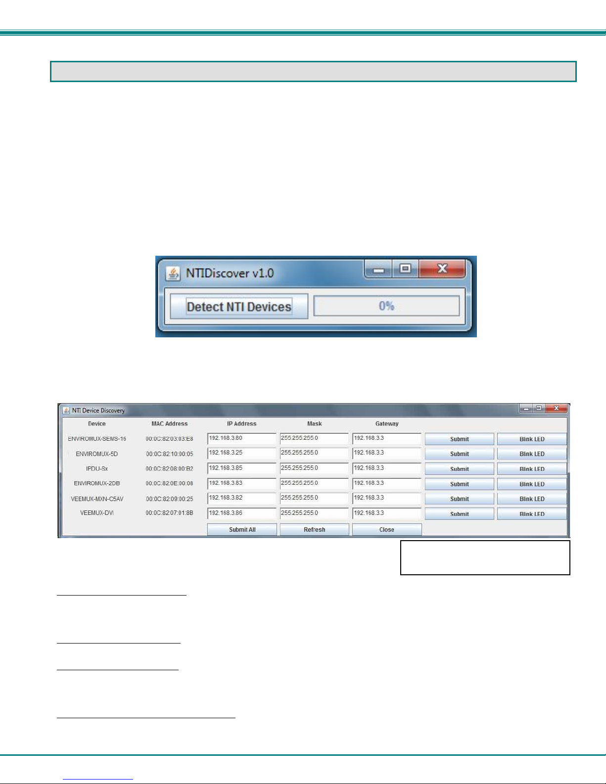
Figure 11- Device Discovery Tool
Click on the “Detect NTI Devices” button to start the discovery process. After a short time, the tool will display all NTI devices on
your network, along with their network settings.
How to Use the Device Discovery Tool
To Change a Device’s Settings
on the Enter key, or the Submit button on that row. If the tool discovers more than one device, the settings for all devices can be
changed and you can click on the Submit All button to submit all changes at once.
To Refresh the list of devices
To Blink the LEDs of the unit
button will change to a “Blinking….” button. The LEDs of the unit will blink until the Blinking… button is clicked on, or the NTI
Device Discovery Application is closed. The LEDs will automatically cease blinking after 2 hours.
To Stop the LEDs of the unit from blinking
button.
, within the row of the device whose settings you wish to change, type in a new setting and click
, click on the Refresh button.
, click on the Blink LED button (This feature is not supported on the IPDU-Sx.) The Blink LED
, click on the Blinking… button. The Blinking…. button will change to a Blink LED
The “Blink LED” button is not
supported on the IPDU-Sx
13
Page 21
NTI Secure Remote Power Reboot Switch
OPERATION VIA WEB INTERFACE
A user may monitor and configure the settings of the IPDU-Sx, the outlets, and any sensor connected to it using the Web Interface
via any web browser (see page 2 for supported web browsers). To access the Web Interface, connect the IPDU-S2 to the
Ethernet (page 5). Use the Device Discovery Tool (page 13) to setup the network settings. Then, to access the web interface
controls, the user must log in.
By default, the IPDU-Sx is configured to dynamically assign network settings received from a DHCP server on the network it is
connected to. (This can be changed to a static IP address to manually enter these settings in the Network Settings on page 33.)
The IPDU-Sx will search for a DHCP server to automatically assign its IP address each time the unit is powered up. If the
IPDU-Sx does not find a DHCP server, the address entered into the static IP address field (page 33 -default address shown
below) will be used. If a DHCP server on the network has assigned the IP address, use the Device Discovery Tool to identify the
IP address to enter when logging in to the IPDU-Sx .
Note: The computer using the Device Discovery Tool and the NTI Device must be connected to the same subnet in order
for the Device Discovery Tool to work. If no devices are found, the message “No Devices Found” will be displayed.
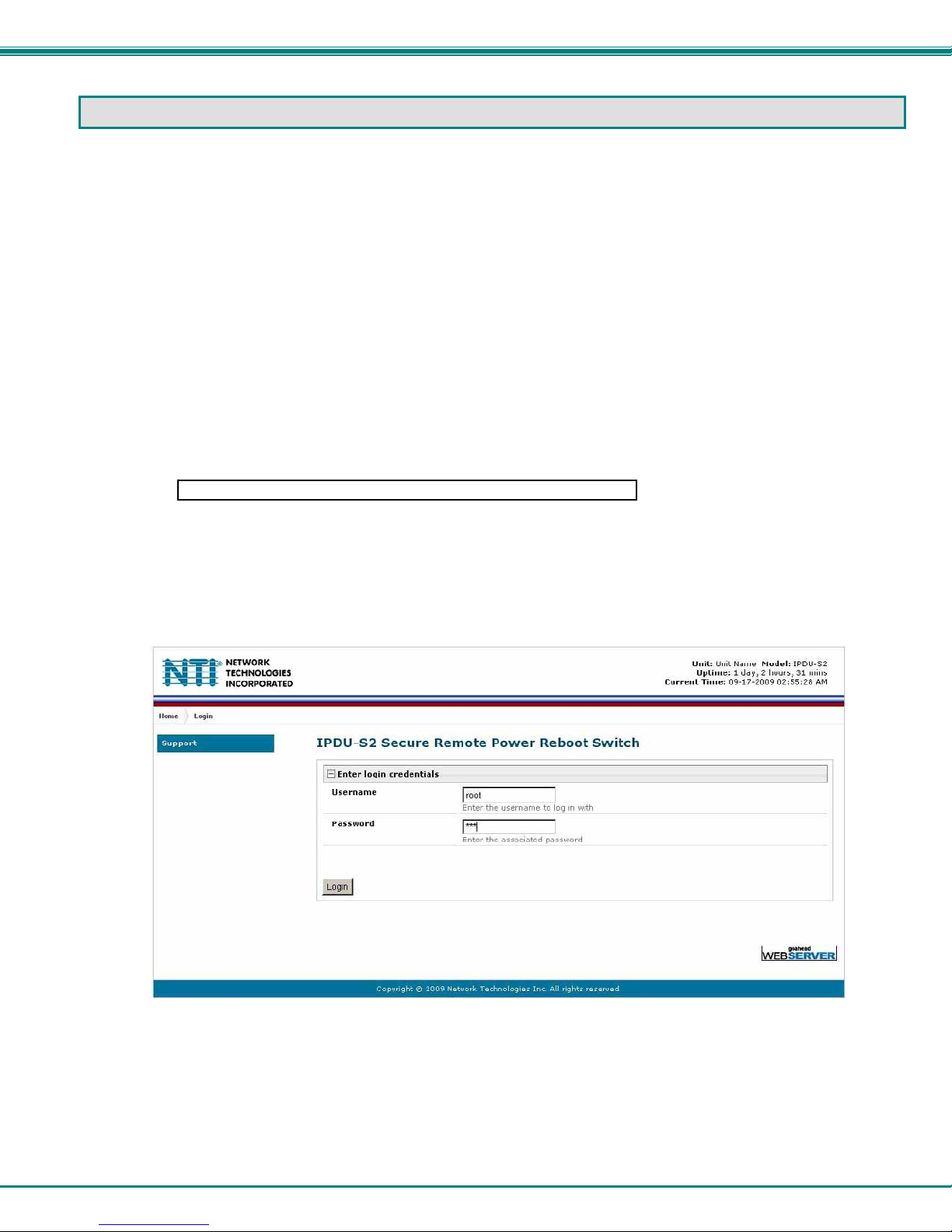
Log In and Enter Password
To access the web interface, type the current IP address into the address bar of the web browser. (The default IP address is
shown below):
http://192.168.1.22
Note: If “Allow HTTP Access” (page 33) is not checked to be enabled (disabled by default) , only an SSL-encrypted
connection will be possible. The software will automatically redirect to an HTTPS (secure) connection. The user will
likely see a warning about the SSL certificate and a prompt to accep t the certificate. The IPDU-Sx uses a self-signed
NTI certificate. Accept the NTI certificate.
A log in prompt requiring a username and password will appear:
Figure 12- Login prompt to access web interface
Username = root
Password = nti
(lower case letters only)
Note: usernames and passwords are case sensitive
14
Page 22
NTI Secure Remote Power Reboot Switch
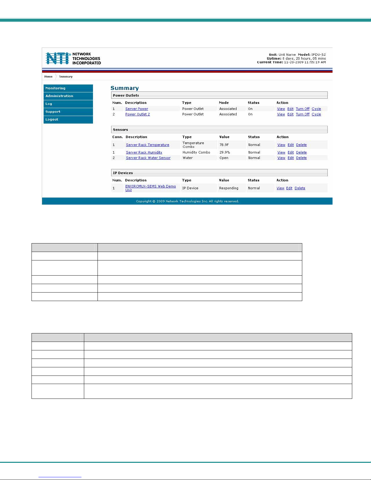
With a successful log in, the “Summary” page with a menu at left will appear on the screen:
Figure 13- Summary page
From this initial page, the user can use the menu to the left to manage all the functions of the IPDU-Sx.
Function Description
MONITORING Monitor the sensors, outlets, and IP devices of the IPDU-Sx (below)
ADMINISTRATION Configure all system, network, multi-user access, and security settings as
well as upgrade firmware (page 30)
LOG View and configure the Event and Data Logs (page 53)
SUPPORT Links for downloading a manual, the MIB file, or firmware upgrades
LOGOUT Log the user out of the IPDU web interface
Monitoring
Under Monitoring, there are links to view the status of the sensors, outlets and IP Devices being monitored by the IPDU-Sx.
Link Description
Summary Lists all items being monitored, including their description, type, value, and status
Power Outlets Provides a link to view the status of only the Power Outlets in the IPDU-Sx (page 17)
Line Monitor Provides a link to view the status of the AC line supplying power to the outlets (IPDU-S4 and -S8 only)
Sensors Provides a link to view the status of only the Sensors and a link to add them (page 22)
IP Devices Provides a link to view the status of only the IP Devices and a link to add them (page 25)
Events Provides a link to view the status of pre-configurable events that would generate alerts (page 28) (IPDU-S4
and -S8 only)
15
Page 23
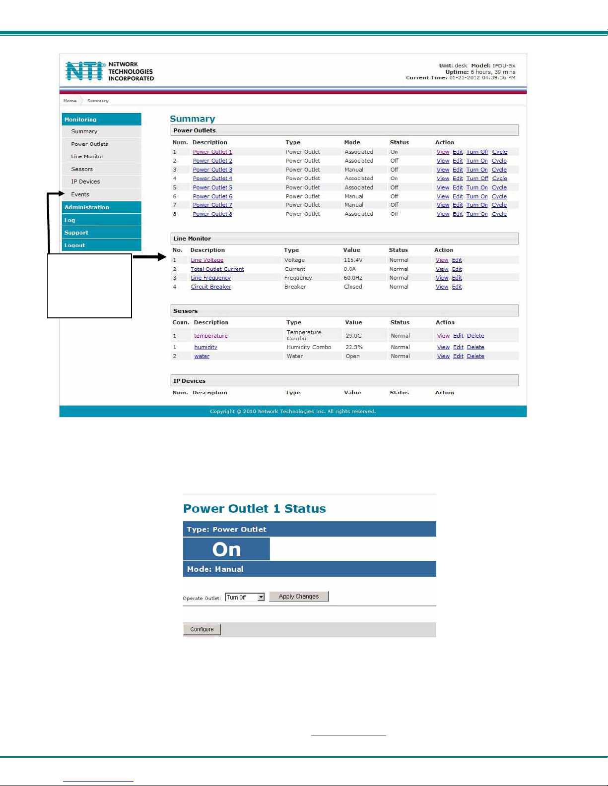
NTI Secure Remote Power Reboot Switch
“Line Monitor”
and “Events”
found only in
IPDU-S4 and
IPDU-S8
Figure 14- Summary page and the Monitoring menu
From the Summary page, the user can view the status of all power outlets, sensors, and the IP Devices being monitored by the
IPDU-Sx. Each item listed has a link that when selected will open the status page for that item.
Figure 15- Status page for a power outlet
If the power outlet is in alert status, the user has the option to either acknowledge the alert or dismiss it. If the user
acknowledges the alert, no additional alert messages will be sent during that alert status cycle. If the user dismisses the alert,
another alert message will be sent once the “notify again after” time designated on the configuration page (pag e 23) elapses.
If the user wants to change the ON/OFF status of an outlet, an option to perform that function is provided. Toggle the status
desired in the window provided, and click Apply Changes.
A Configure button at the bottom of each page allows the user (administrators only
) to configure parameters of the power outlet.
16
Page 24
NTI Secure Remote Power Reboot Switch
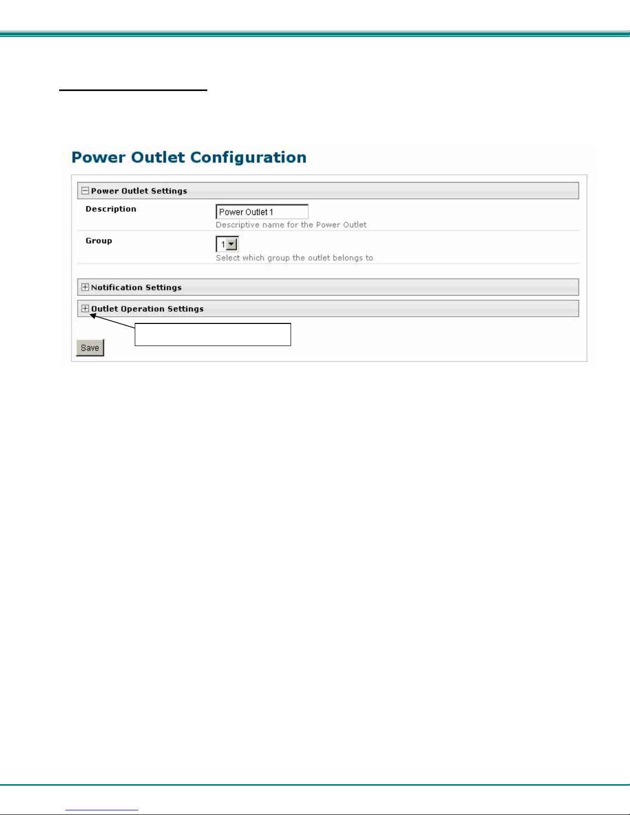
Configure a Power Outlet
The Power Outlet Configuration page allows the user to apply settings to control how or if alert messages are sent in the event the
outlet changes state. The user can open the Power Outlet Configuration page by clicking on the Configure button at the bottom
of the Power Outlet Status page (page 16) or by clicking on Edit from the Summary page.
click to expose more settings
Figure 16- Power Outlet Configuration page
The Power Outlet Configuration page is broken into three sections; Power Outlet Settings, Notification Settings and Outlet
Operation Settings. To explode the window to see Notification Settings or Outlet Operation Settings (Figure 17), click on the
section heading (Figure 16).
17
Page 25
NTI Secure Remote Power Reboot Switch
T
his field only found in IPDU-S4
and IPDU-S8
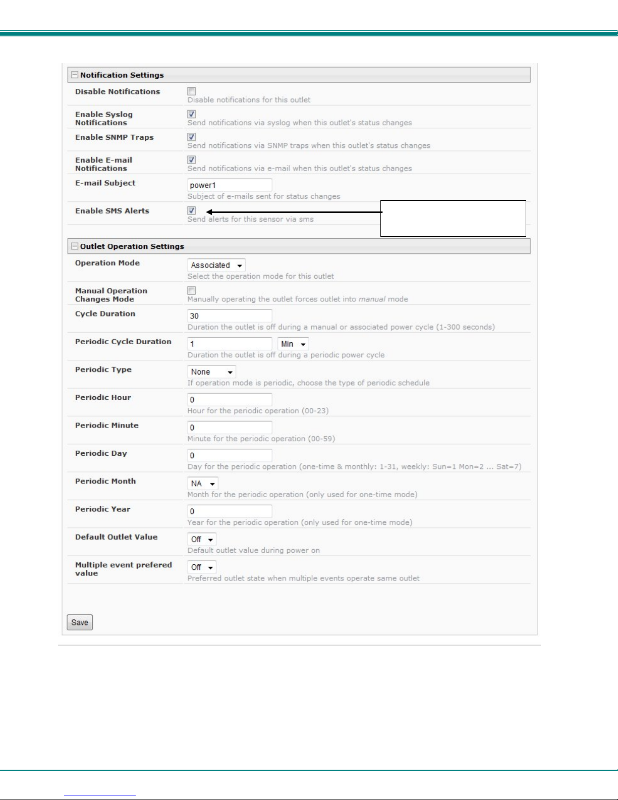
Figure 17- More settings for Power Outlet Configuration
18
Page 26

NTI Secure Remote Power Reboot Switch
Power Outlet Settings Description
Description The description of the outlet that will be viewed in the Summary page and in the body of alert
messages
Group Assign the outlet to either group 1 or 2
Notification Settings
Disable Notifications Place a checkmark in the box to prevent notifications from being sent when this outlet’s status
changes
Enable Syslog Notifications Place a checkmark in this box to have alert notifications sent via Syslog messages
Enable SNMP traps Place a checkmark in this box to have alert notifications sent via SNMP traps (v2c)
Enable Email Notifications Place a checkmark in this box to have alert notifications sent via Email
Email Subject Enter the subject to be viewed when an email alert message is received
Enable SMS Alerts
(IPDU-S4 / -S8 only)
Outlet Operation Settings
Operation Mode Choose between Manual, Periodic, or Associated operating modes for the outlet
Manual Operation Changes
Mode
Cycle Duration Time period (1-300 seconds) the outlet will remain OFF during a manual power cycle or an
Periodic Cycle Duration Time period in minutes or hours the outlet will remain OFF during a periodic power cycle
Periodic Type If the operation mode is set to periodic, choose the type of periodic schedule between one time,
Periodic Hour Choose which hour of the day for the periodic cycle to occur (00-23)
Periodic Minute Choose the minute within the hour of the day for the periodic cycle to occur (00-59)
Periodic Day Choose the day for the periodic cycle to occur (for one-time and monthly settings, enter a value
Periodic Month Choose which month of the year for the periodic cycle to occur. This only applies when the
Periodic Year Enter the year for the periodic cycle to occur. This only applies when the P eriodic Type is set to
Default outlet value Choose the state of the outlet at power-On of the IPDU- Outlet ON or Off
Multiple Event Preferred Value Choose the preferred outlet state when more than one event can control the outl et
Place a checkmark in this box to have alert notifications sent via SMS message (requires
modem)
Place a checkmark here if you want the operating mode to be forced into Manual mode if you
manually override the outlet status from the Power Outlet Status page (page 16)
associated power cycle
daily, weekly, monthly, or none
between 1-31; for weekly setting, enter a value 1-7, Sun = 1, Mon=2 .....Sat = 7)
Periodic Type is set to “one time”.
“one time”.
(if one event is configured to turn the outlet OFF, and another event to turn the outlet ON, this
setting will decide the state of the outlet)
Note: Alerts are also indicated by illuminated LEDs on the front of the IPDU-Sx (page 7).
More about Groups
Groups are used to create a common relationship between sensors, IP devices, power outlets, etc. and their alert messages. All
items being monitored are assigned to either group 1 or group 2. All users (a maximum number of 16 including the root user) can
either receive alert messages from items in group 1, group 2, both groups, or neither.
Be sure to press the Save button to save the configuration settings.
More about Operation Modes
In Manual Mode, the outlet will only power cycle when it is performed through the Power Outlet Status page or through the text
menu.
In Periodic Mode, the outlet will power cycle based on the settings configured as described in the table above.
In Associated Mode, the outlet can be controlled based on the alert status of a sensor or IP address. When configured to do so
(page 24), the outlet can be powered ON or OFF when a sensor is in alert mode, and/or when it returns to normal state, or power
cycled when an IP Device is in alert mode.
Note: An outlet configured for Associated or Periodic operating mode can be manually powered ON/OFF. If “Manual
Operation Changes Mode” (above) is checked, manually changing the ON/OFF state of an outlet configured for
Associated Mode or Periodic Mode will change the operating mode to Manual Mode until the outlet is reconfigured.
19
Page 27
NTI Secure Remote Power Reboot Switch
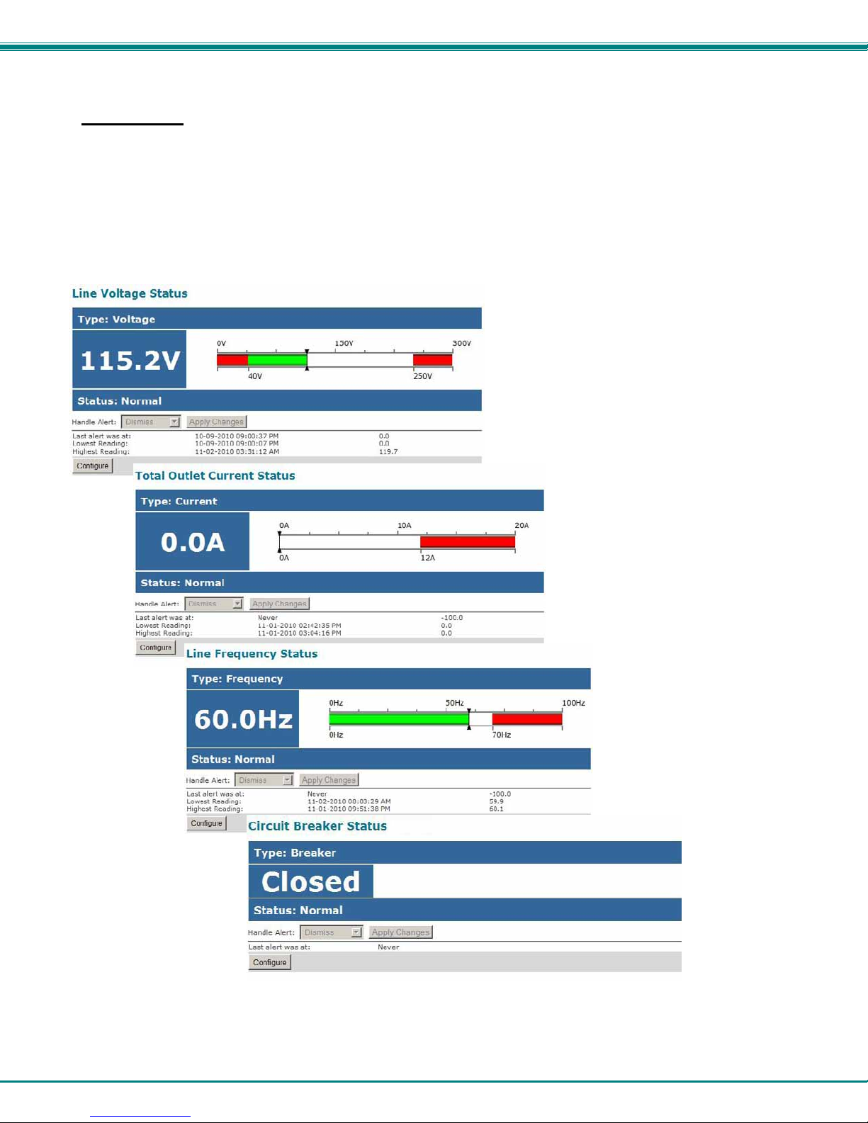
Line Monitor
The Line Monitor on the Summary Page provides a quick way to view the amount of power that is being used by the IPDU-S4 or
IPDU-S8. From the Summary Page the user will find displayed:
• Line Voltage Status- the value of the voltage being supplied
• Total Outlet Current Status- the total amount of current being used by all of the outlets combined (also viewed
in the LED display on the front of the IPDU-S4 and IPDU-S8)
• Line Frequency Status- the frequency of the power being supplied
• Circuit Breaker Status- the status of the circuit breaker on the rear of the unit.
Figure 18- Line Monitor Categories
20
Page 28
NTI Secure Remote Power Reboot Switch
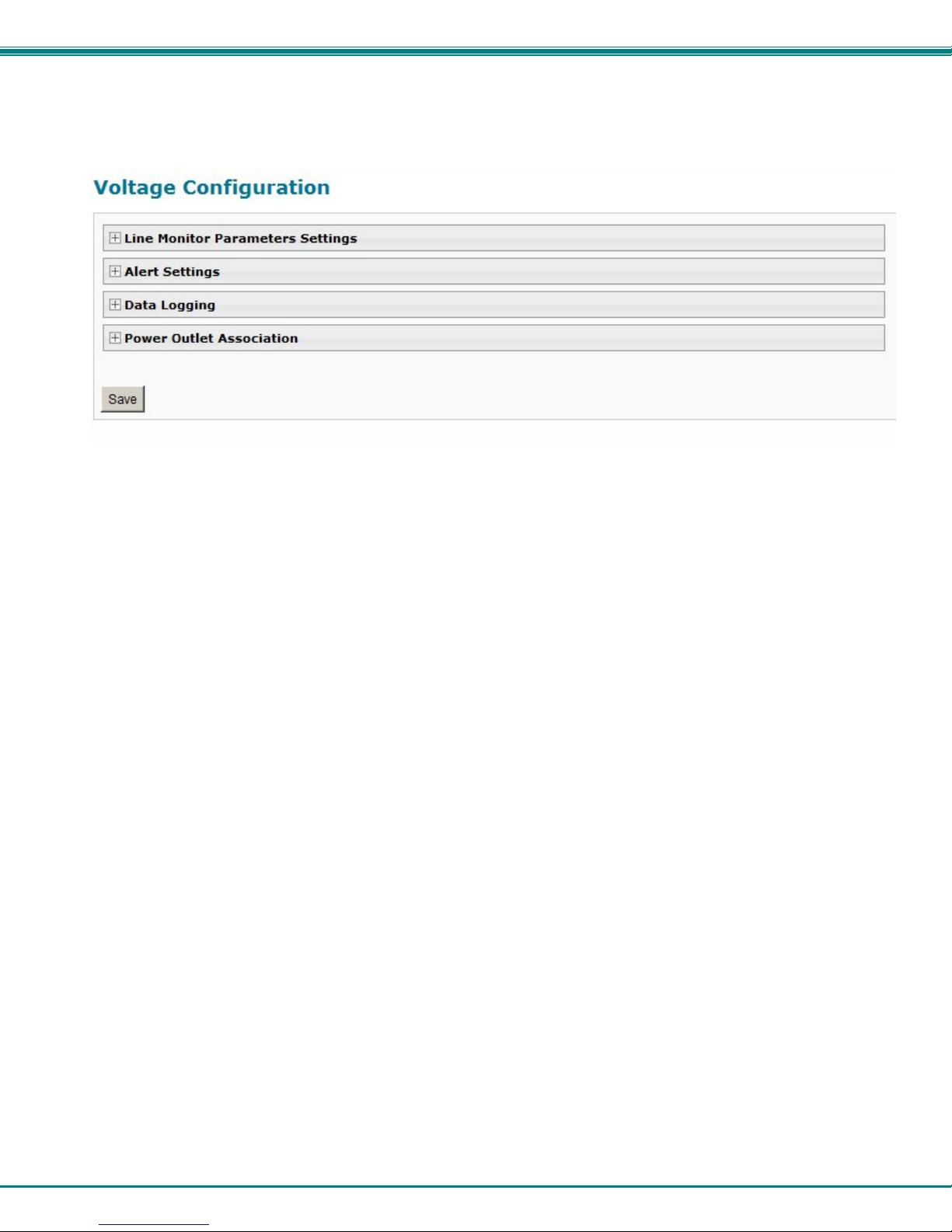
Each category of line monitoring is configurable much like sensors are configured. For more on config uration, see “Monitor and
Configure Sensors” on next page.
Figure 19- Configuration Categories
21
Page 29

NTI Secure Remote Power Reboot Switch
Monitor and Configure Sensors
To view the graphic image showing the status of a sensor, click on the sensor description in the Summary page. From the sens or
status page, the user can view a current reading, either dismiss or acknowledge an alert, or open the sensor configuration page (if
the user has administrative privileges).
Figure 20- Sensor Status page
The administrative user can open the sensor configuration page by clickin g on the Configure button at the bottom of the sens or
status page (above) or by clicking on Edit from the Summary page. From the sensor configuration page the user can apply
settings to control how or if alert messages are sent in the event the sensor is in alert status, threshold settings, data logging
settings, and power outlet association.
Figure 21- Sensor Configuration page
22
Page 30
NTI Secure Remote Power Reboot Switch
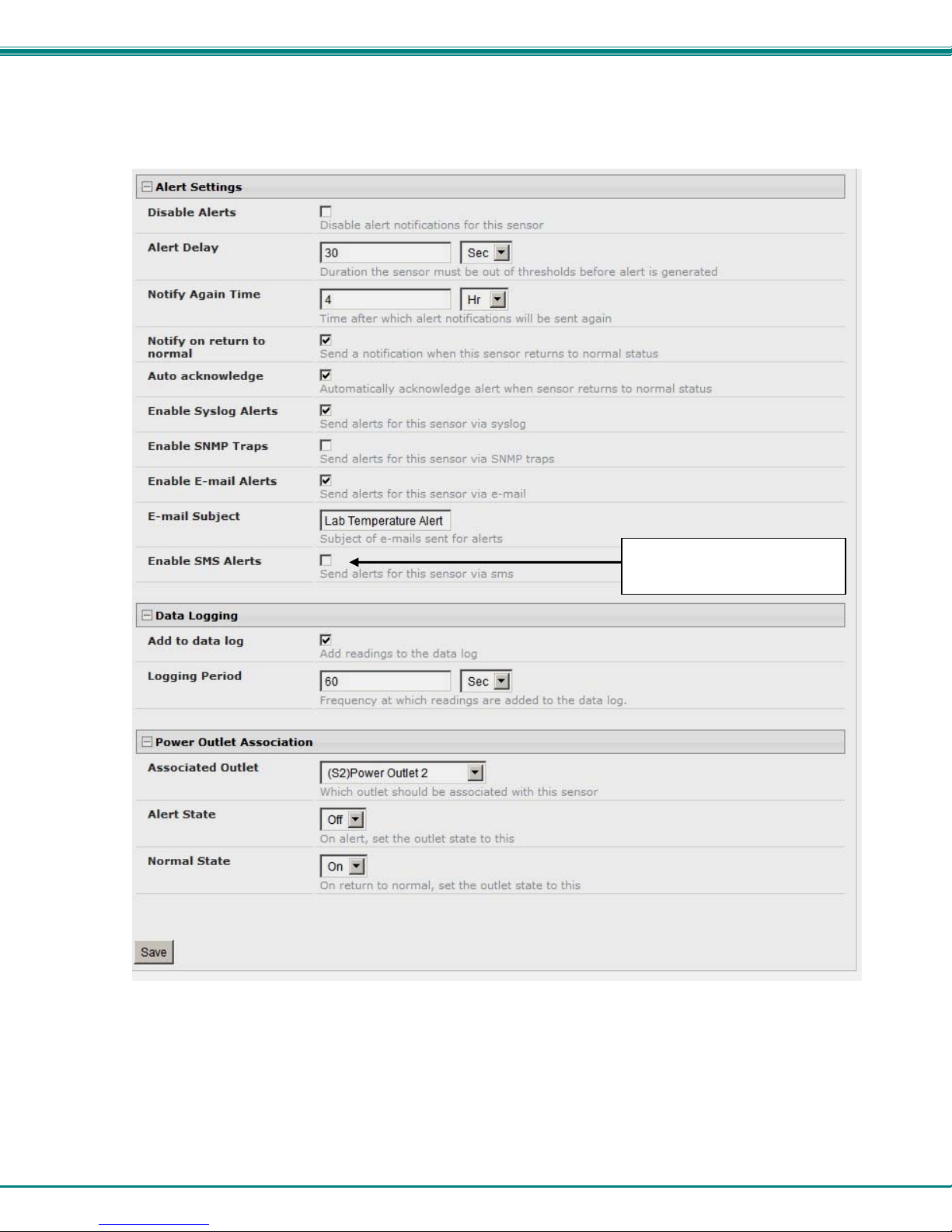
T
The Sensor Configuration page is broken into four sections; Sensor Settings, Alert Settings and Data Logging, and Power Outlet
Association. To explode the window to see settings for a section, click on the section heading (Figure 21).
his field only found in IPDU-S4
and IPDU-S8
Figure 22- Sensor Configuration- full view of settings
23
Page 31

NTI Secure Remote Power Reboot Switch
Sensor Settings Description
Description The description of the sensor that will be viewed in the Summary page and in the body of alert
messages
Group Assign the sensor to either group 1 or 2 (see also page 45)
Units This lets the operator choose between Celsius and Fahrenheit as the temperature
measurement unit.
Min. Level Displays the minimum value that this sensor will report
Max. Level Displays the maximum value that this sensor will report
Sampling Period Determines how often the displayed sensor value is refreshed on the Sensor page. A numeric
value and a measurement unit (minimum 1 seconds, maximum 999 minutes) should be entered.
Minimum Threshold The user must define the lowest acceptable value for the sensors. If the sensor measures a
value below this threshold, the sensor will move to alert status. The assigned value should be
within the range defined by Minimum Level and Maximum Level and lower than the assigned
Maximum Threshold value. If values out of the range are entered, and error message will be
shown.
Maximum Threshold The user must define the highest acceptable value for the sensors. If the sensor measures a
value above this threshold, the sensor will move to alert status. The assigned value should be
within the range defined by Minimum Level and Maximum Level and higher than the assigned
Minimum Threshold value. If values out of the range are entered, and error message will be
shown.
Alert Settings
Disable Alerts Place a checkmark in the box to prevent alerts from being sent when this sensor’s status
changes
Alert Delay The alert delay is an amount of time the sensor must be in an alert condition before an alert is
sent. This provides some protection against false alarms. The Alert Delay value can be set
for 0-999 seconds or minutes.
Notify Again Time Enter the amount of time in seconds, minutes, or hours (1-999) before an alert message will be
repeated
Notify on Return to Normal The user can also be notified when the sensor readings have returned to the normal range by
selecting the "Notify when return to normal" box for a sensor.
Auto Acknowledge Place a checkmark in this box to have alert notifications in the summary page return to normal
state automatically when sensor readings return to normal.
Enable Syslog Alerts Place a checkmark in this box to have alert notifications sent via Syslog messages
Enable SNMP traps Place a checkmark in this box to have alert notifications sent via SNMP traps (v2c)
Enable Email Alerts Place a checkmark in this box to have alert notifications sent via Email
Email Subject Enter the subject to be viewed when an ema il alert message is received
Enable SMS Alerts
(IPDU-S4 / -S8 only)
Data Logging
Add to data log This is a check-box that lets the user decide if the data sampled should be recorded in the Data
Logging Period Enter the time period between logged measurements
Power Outlet Association
Associated outlet Select which outlet (if any) will be powered ON or OFF when the sensor is in an alert state.
Alert State State the outlet should be in when the sensor enters an alert state
Normal State State the outlet should be in when the sensor returns to normal state
Be sure to press the Save button to save the configuration settings.
Place a checkmark in this box to have alert notifications sent via SMS messages (required
modem)
Log.
For this to take effect, the outlet must be configured for Associated Operation Mode (page 19)
24
Page 32

NTI Secure Remote Power Reboot Switch
Monitor IP Devices
IP devices such as servers, routers, cameras, etc. can be monitored to make sure network connections are open to them. In
order to monitor an IP Device the devices must be added to the list of IP Devices being monitored. From the Monitoring section
of the menu, click on IP Devices. A page listing IP Devices being monitored will open, with a link to add IP Devices. Click on
Add New IP Device.
Figure 23- IP Devices listing-none monitored yet
The page shown below will open. Enter a description for the new IP Device and the IP Address of the device.
Figure 24- Add New IP Device page
With the address is entered in the block, click on the “Add” button.
25
Page 33

NTI Secure Remote Power Reboot Switch
The IP Device Configuration page will immediately open. Here you can configure the IPDU-Sx to ping the IP Device a s often as
desired and to react to a lack of response by sending alert messages and/or power-cycling a power outlet.
Figure 25- IP Device Configuration page
IP Device Settings Description
Description The description of the IP Device that will be viewed in the Summary page and in the body of alert
messages
IP Address The IP address of the IP Device
Group Assign the IP Device to either group 1 or 2
Ping Period Enter the frequency in minutes or seconds that the IPDU-S2 should ping the IP Device
Timeout Enter the length of time in seconds to wait for a response to a ping before considering the attempt a
failure
Retries Enter the number of times the IPDU-S2 should ping a non-responsive IP device before changing its
status from normal to alarm and sending an alert
The alert settings and data logging are the same as for sensor configuration, described on page 24. Under Power Outlet
Association, if the IP device is connected to one of the power outlets on the IPDU-Sx, the IPDU-Sx can automatically cycle the
power to the chosen outlet when the IP device is determined to be in a state of alarm. The power cycle characteristics will be
those configured under the power outlet configuration under “Outlet Operation Settings” (page 19).
26
Page 34

NTI Secure Remote Power Reboot Switch
Figure 26- Power Outlet Association for IP Device
With a couple of IP devices having been configured for monitoring, the IP Device list will provide links to them for viewing their
status, editing their configuration, or deleting them from the list.
Figure 27- IP Device list with new devices added
To view the graphic image showing the status of an IP address, click on the IP Device description or click View. From the IP
Device status page, the user can view the current status, either dismiss or acknowledge an alert, or open the IP Device
configuration page (if the user has administrative privileges). If you have found the device to be in an alert state and have either
dismissed or acknowledged it, be sure to click the Apply Changes button.
Figure 28- IP Device Status page
27
Page 35

NTI Secure Remote Power Reboot Switch
Monitor Events
The IPDU (models IPDU-S4 and IPDU-S8 only) can be configure to respond to predefined events. Once the criteria is set for
what constitutes an event, an alert can be sent and/or devices connected to outlets can be controlled. Up to 50 events can be
configured.
Figure 29- Event Monitoring
From the Events list, select “Add New Event”. A page with a drop-down list of available sensors to choose from is presented.
Select the sensor you want to use to send an alert if specific conditions are reached.
Figure 30- Add New Event
A configuration page will appear with fields for
determining under what circumstances you should
receive an alert from a sensor and what, if
anything should be done about it.
The settings applied here have no bearing on the
sensor configuration settings applied when the
sensor is setup (page 23). These settings only
apply to the event being configured.
Many of the same fields described in the sensor
configuration page (page 24) are used for event
configuration.
Event descriptions can be anything you want, up
to 80 characters in length. These descriptions will
appear in the Event Log when events are
recorded.
Note: Once you open the “New Event
Configuration” page for an event, that event
will be added to the list of events (next page).
To remove the event, see next page.
Note: If more than one
event is triggered, and
both are associated
with the same outlet but
have opposing Alert
States, the state set for
“Multiple event
preferred value” under
outlet configuration
(page 17) will determine
the outlet state.
Figure 31- Configure New Event
28
Page 36

NTI Secure Remote Power Reboot Switch
Once events are configured, they are listed and numbered for monitoring and easy adjustment. Up to 50 can be configured.
Figure 32- List of Configured Event
If an event is triggered, the Status will change from “Normal” to “Alarm”. Whatever reaction that has been configured as a result
of this event will be activated.
The user will have the option to either Acknowledge the alert, Dismiss it, or Delete the configuration of the event altogether.
If the user acknowledges the alert, no additional alert messages will be sent during that alert status cycle. If the user dismisses
the alert, another alert message will be sent once the “notify again after” time designated on the configu r ation page elapses.
To see the status page for a sensor, click on the link under “Curr. Val.”. To see the status of an associated outlet, click on the
link under “Assoc Outlet”.
To delete an event configuration, select “Delete” to the far right of the event number. That configuration will be removed and the
one following it (if any) will move up to that event number.
Note: Removal of a sensor from the IPDU will also remove all configured events associated with that sensor.
Click on the description for an event to open the configuration page for editing.
Figure 33- Adjust settings for events
All settings for an event can be adjusted as needed. Be sure to click “Save” before exiting.
29
Page 37

NTI Secure Remote Power Reboot Switch
Administration
From the Administration section there are several sub sections for configuring the IPDU-S2:
System Fields for applying time zone, date, time, NTP server, and backup and restore
configuration settings
Enterprise Fields for assigning the unit name, address, contact person, the IPDU-S2 e-mail
address, and phone number of a contact person
Network Fields for providing all th e network settings the IPDU-Sx including IP address,
DNS, SMTP and SNMP settings
Cascade Fields for configuring this IPDU to control multiple IPDUs or be controlled by
another IPDU- (models IPDU-S4 and IPDU-S8 only)
Users Fields for assigning users, access privileges, passwords, contact settings, and
schedule settings
Security Fields for setting authentication method and IP Filtering
System
Information
Firmware For updating the firmware of the IPDU-Sx when improved software becomes
Reboot Enables user to reboot the IPDU-Sx using th e web interface
For viewing IPDU-Sx system information
available.
System Configuration
The System Configuration section is where all the settings necessary for proper time reporting within alert messages and log
records are configured. To view the System Configuration page, click on System from the Administration section of the menu.
Figure 34- System Configuration page
30
Page 38

NTI Secure Remote Power Reboot Switch
The Date and Time of the IPDU-Sx can be either manually setup to use an onboard clock or set to be synchronized wi th an NTP
server. The configuration of the IPDU-Sx can also be easily backed up to a file on your PC and restored from that file as
needed.
Time Settings Description
Time Zone Enter the appropriate time zone
Enable Daylight Saving Apply a checkmark to have the time change according to Daylight Saving Time rules
Set Date Enter the system date in MM-DD-YYYY format
Set Time Enter the system time of day in hh:mm:ss format
Enable NTP Place a checkmark to enable the IPDU-Sx to automatically sync up with a time server via NTP
NTP server If the NTP is enabled, enter the IP address of the NTP server
NTP Frequency Enter the frequency (in minutes) for the IPDU-Sx to query the NTP server (minimum is 5
minutes)
Configuration Backup &
Restore
Choose file Browse for a saved configuration file to be restored to the IPDU-Sx. After selection, press the “
Download Configuration File Click this button to save the configuration of the IPDU-Sx to a location on your PC. This file
Restore Defaults Click this button to restore the IPDU-Sx to the configuration settings it had upon receipt from the
”Save” button and the IPDU-Sx will restore the configuration settings and reboot. Allow 1
minute before trying to reconnect and log in again.
Note: The IP address will be set to the IP address in the file and may be different
can be restored using the “Choose file” field in the event you wish to return the IPDU-Sx to a
former state
factory. Be careful! This will erase all
user configuration settings. Upon restoration, the
IPDU-Sx will reboot. Allow 1 minute before trying to reconnect and log in again.
Confirmation is required.
Note: If “Restore Defaults” is used, the IP address will also be restored to its default address of 192.168.1.22 with a login
name “root” and password “nti”. To restore the root password to “nti” without having to restore all default settings,
contact NTI for assistance.
To identify the IP address of the IPDU-Sx without restoring defaults, use the Discovery Tool (page 13).
Click on Save when finished with Time Setting changes.
31
Page 39

NTI Secure Remote Power Reboot Switch
Enterprise Configuration
The Enterprise Configuration page is used to enter basic company information to be applied to the body of alerts. To view the
Enterprise Configuration, click on Enterprise from the Administration section of the menu. Enter in the blocks your unit name,
location, the contact person that alert e-mails should refer to, the phone number to reach that person, and the e-mail address
assigned to the IPDU-Sx. Alert message sent via email, syslog and SNMP will include the information in these blocks.
The IPDU-S4 and IPDU-S8 additionally has a section for the GSM modem status. A GSM modem must be installed in order to
send SMS messages. If a GSM modem is properly installed (page 8), the type, status, IMEI number, and signal strength will be
displayed. The modem will work with a signal strength between -111dBm (weak) and -51dBm (strong). If a modem is not
installed, the words “not available” will be displayed instead for the modem type.
Note: It may take several minutes for the GSM modem to be detected by the IPDU-Sx.
GSM modem is properly installed
Figure 35- Enterprise Configuration
32
Page 40

NTI Secure Remote Power Reboot Switch
Network Configuration
From the Network Setup page the administrator can either choose to have the IP address and DNS infor m ation filled in
automatically by the DHCP server (default setting), or manually fill in the fields (use a static address). To view the Network
Configuration page, click on Network from the Administration section of the menu.
Note: When “DHCP” is selected, make sure a DHCP server is running on the network the IPDU-Sx is connected to.
Note: The values shown here are
for local (static) address
configuration only.
Address values for DHCP
configuration will only be displayed
in the System Information page
(page 50).
Only applicable to IPDU-S4/S8
models- firmware version 1.4 or
later.
Figure 36- Network Configuration page
IP Settings Description
Mode Select between Static (manual) , or DHCP (automatic IP and DNS) settings (DHCP is the
default setting)
IP Address Enter a valid IP address (default address shown above)
Subnet Mask Enter a valid subnet mask (default value shown above)
Default Gateway Enter a valid gateway (default gateway shown above)
Preferred DNS Enter a preferred domain name server address
Alternate DNS Enter an alternate domain name server address
For descriptions of SMTP, SNMP, and Server Settings, see page 35. .
33
Page 41

NTI Secure Remote Power Reboot Switch
The Network Configuration page is broken into seven sections; IP Settings, SMTP Settings, SNMP Settings, Server Settings, and
IP Alias 1, 2,and 3 Settings. To explode the window to see settings for a section, click on the section heading.
Common Port numbers:
Default: 25 (Not secure)
SSL: 465 (Secure)
TLS: 587 (Secure)
Contact your network
administrator for required
settings.
Figure 37- Network Configuration- more settings
34
Page 42

NTI Secure Remote Power Reboot Switch
More Network Settings (see Figure 37)
SMTP Settings Description
SMTP Server Enter a valid SMTP server name (e.g. yourcompany.com)
Port Enter a valid port number (default port is 25)
Use SSL Place a checkmark in the bo x if the SMTP server supports SSL
Use TLS Place a checkmark in the box if the SMTP server supports TLS
Use Authentication Place a checkmark in the box if the SMTP server requires authentication to send email
Username
Password
SNMP Settings
Enable SNMP agent Place a checkmark in the box to enable access to the SNMP agent
Enable SNMP traps Place a checkmark in the box to allow SNMP traps to be sent
Read-write community name Enter applicable name (commonly used- “private”) CASE SENSITIVE
Read-only community name Enter applicable name (commonly used- “public”) CASE SENSITIVE
Server Settings
Enable Telnet
Enable SSH
Enabe HTTP access
HTTP Port Port to be used for standard HTTP requests
HTTPS Port Port to be used for HTTPS requests
Web Timeout Number of minutes after which idle web uses will be logged-out (enter 0 to disable this feature)
If the administrator chooses to have the IP and DNS information filled in automatically via DHCP, the SMTP server and port
number still need to be entered for email alerts to work. If the SMTP server requires a password in order for users to send emails,
the network administrator must first assign a user name and password to the IPDU.
Enter a valid username to be used by the IPDU-Sx to send emails
Enter a valid password assigned to the IPDU-Sx username
Place a checkmark in the box to enable access to the IPDU-Sx via Telnet
Place a checkmark in the box to enable access to the IPDU-Sx via SSH
Place a checkmark in the box to enable access to the IPDU-Sx via standard (non-secure) HTTP
requests
Note: The SMTP server port number is shown in Figure 37 as "25". This is a common port number assigned, but not
necessarily the port number assigned to your SMTP server. For SMTP servers that support SSL, the common port
number is 465, and for those that support TLS, the common port number is 587.
The administrator may assign a different HTTP Server Port than is used by most servers (80).
Note: If the port number is changed and forgotten, to determine what it has been changed to connect the IPDU-SX for
RS232 control (page 6) and review the Network Settings (page 33).
Read-Only Community Name
The SNMP Read-only community name enables a user to retrieve "read-only" information from the IPDU-Sx using SNMP network
management software or a MIB browser and a MIB file. This name must be present in the IPDU-Sx and in the proper field in the
SNMP software. This name is case sensitive
Read-Write Community Name
The SNMP Read-Write community name enables a user to read information from the IPDU-Sx and to modify settings on the
IPDU-Sx using SNMP network management software or a MIB browser and MIB file (MIB file version 1.01 or later). This name
must be present in the IPDU-Sx AND in the proper field in the SNMP software. This name is case sensitive
correctly in the IPDU-Sx as well as in the SNMP software.
This function is particularly useful if you want to control the state of the Output Relays (page 16) through SNMP. With
the IPDU-Sx and SNMP network management software properly configured for SNMP control (enable agent, enable traps,
apply Read-only and Read-write Community Names), a SET command can be sent either from the SNMP software or MIB
browser (Windows) or through command line (Linux) to change the outputRelay value state. See images on page 37 for
example of setup.
Note: The Read-Write Community Name field is only functional in the IPDU-S4/S8 models. It does not apply to the
IPDU-S2.
so be sure to enter it correctly in the IPDU-Sx as well as in the SNMP software.
Only applicable to IPDU-S4/S8- F i rmware version 1.3 or later
so be sure to enter it
35
Page 43

NTI Secure Remote Power Reboot Switch
Figure 38- IP Aliases
IP Aliases
Up to 3 IP aliases can be configured. This provides added flexibility when access from multiple networks is required.
To use an alias, be sure to change the default Mode to “Enable”. Then enter a valid IP address, Subnet Mask and Gateway for
the network that will have access to the ENVIROMUX.
Only the primary IP Settings can be assigned by a DHCP server and only the primary settings can have DNS Server settings.
Only the primary IP settings are used for any outgoing connections like alert emails, syslog etc.
Only applicable to IPDU-S4/S8- Fi rmware version 1.4 or later
36
Page 44

NTI Secure Remote Power Reboot Switch
)
Note: enter same values from IPDU to the MIB browser
3. Expand the tree to view the
relay output values (right click
-> Get Subtree)
5. Change “Value” to 1 (for On)
or 0 (for Off). Click “OK”.
(public)
1. Configure the IPDU (Network Settings
(private)
2. Configure the MIB browser
4. Identify which Output to
change state (power On or
power Off), right click and
choose Set
6. Confirmation of state
change.
Figure 39- Setup SNMP to control output relays
37
Page 45

NTI Secure Remote Power Reboot Switch
Cascade Configuration
The Cascade Configuration page is used (IPDU-S4 and IPDU-S8 only) to control multiple IPDU-Sx units, connecting them to one
another to form a much larger system that can be administered and monitored from one central point. Units can be cascade
using either RS485 or Ethernet connection. When using the RS485 Connection method for cascading the IPDU-Sx will be
connected as shown on page 8. If units will be controlled using the Ethernet Connection method, the IP DU-Sx will be connected
to a network using the “ETHERNET” port.
In a cascaded configuration, one unit will be the “master” to which each unit is connected as a “slave”. Up to 16 slave units can
be connected for a total system configuration of 136 controlled outlets.
If an IPDU-S4 or IPDU-S8 is going to be added to a cascaded system as a slave unit, then the only configuration settings that
need to be applied to the slave unit before it can be enabled in the master unit include:
• Enterprise Name (on the Enterprise Configuration page (page 32)
• IP Settings (on the Network Configuration page (page 33) and only
• Cascade Configuration for RS485 slave or Ethernet Slave (page 39)
Configure the Type
On the Cascade Configuration page the first setting to configure is the type. Types include:
Type Description
Master with No Slaves Stand alone unit, not cascaded, no settings needed
RS485 Slave Unit will be connected to a master using the “Cascade” ports
Ethernet Slave Unit will be connected to a master using the Ethernet
RS485 Master Unit will be the master in a RS485 connected configuration
Ethernet Master Unit will be the master using the Ethernet
if the unit is an Ethernet slave
Figure 40- Cascading- Set the configuration type
38
Page 46

NTI Secure Remote Power Reboot Switch
RS485 Slave
If the type is RS485 Slave, an address number (1-255) must be entered to identify the unit to the master. Each slave on the
system must have a unique address number.
Figure 41- Configure as RS485 Slave
Ethernet Slave
If the type is Ethernet Slave, the Ethernet address entered on the Network Configuration page (page 33) will be used by the
master to communicate with this slave. Each slave on the system must have a unique IP address.
Figure 42- Configure as Ethernet Slave
39
Page 47

NTI Secure Remote Power Reboot Switch
RS485 Master
If the type is RS485 Master, then the RS485 addresses for each slave (valid address range of 1-255) must be entered into the
available blocks (up to 16) in order to communicate between the master and each slave. Once an RS485 address has been
entered, and the RS485 slave has been properly configured to be cascaded as part of this system, place a checkmark in the
“Enable Slave” block.
Figure 43- Configure as RS485 Master
40
Page 48

NTI Secure Remote Power Reboot Switch
Ethernet Master
If the type is Ethernet Master, then the Slave IP Address Settings must be entered for each slave that will be controlled. The IP
address will be used by the master to locate and communicate with the slave. Once an IP address has been entered, and the
Ethernet slave has been properly configured to be cascaded as part of this system, place a checkmark in the “Enable Slave”
block.
Figure 44- Configure as Ethernet Master
41
Page 49

NTI Secure Remote Power Reboot Switch
Cascade Notification
In the event a slave goes offline from the system, the system can be set to notify those configured to receive messages from the
master unit. In the Cascade menu under Administration, the “Cascade Notification Settings” menu provides a place to configure
how frequent notifications will be repeated. Cascade Notification cannot be disabled.
Figure 45- Cascade Notification Settings
An example of the notification you will receive is:
11-12-2010 11:18:38 AM Sensor Not Responding -- Slave Unit #2 (Unit Name) not
responding
Suggestion: To avoid receiving unnecessary notifications, don’t enable the slave (Figure 43 and Figure 44) wh en
configuring the master until the slave has been fully configured first.
The default time period in which notifications will repeat is every 30 seconds.
The number value range for the time period is 1-99, and the units can be seconds (Sec), minutes (Min), or hours (Hr).
42
Page 50

NTI Secure Remote Power Reboot Switch
User Configuration
The Users page is a list of all configured users of the IPDU-Sx. A maximum of 15 users (other than root) can be configured.
From this page the user can choose to add more users, go to the user configuration page to edit a user’s access to the IPDU-Sx,
or delete a user from the list. To view the Users page, click on Users from the Administration section of the menu.
Figure 46- Users page
To add a user, click on the “Add New User” link.
To edit a user’s configuration, either click on the listed username, or on the “Edit” link.
To delete a user and their configuration, click on “Delete” link.
When adding a new user, the Configure User page will open with the username “userx” assigned, where x = the next
consecutive number (up to 15) based on the quantity of users in the list (other than the root user). You can either leave the
name as “userx”, or change it to what you would like to see listed. With the name assigned, fill in the remaining information as
needed.
Figure 47- Configure Users page
43
Page 51

NTI Secure Remote Power Reboot Switch
I
y
PDU-S4/S8 onl
Figure 48- Configure User- more options
Account Settings Description
Username Enter the desired username for this user
Admin Place a checkmark here if this user should have administrative privileges
Enabled
Password Enter a password that a user must use to login to the system
Confirm Re-enter a password that a user must use to login to the system
Title Enter information as applicable
Department Enter information as applicable
Company Enter information as applicable
Place a checkmark here to enable this user to access the IPDU-Sx
A password must be assigned for the user’s login to be valid
Passwords must be at least 1 keyboard character.
44
Page 52

NTI Secure Remote Power Reboot Switch
LDAP Account Settings
Common Name (for LDAP)
Organizational Unit (for LDAP)
Contact Settings
Group 1 Place a checkmark if the user should receive messages from sensors, IP devices and outlets in
Group 2 Place a checkmark if the user should receive messages from sensors, IP devices and outlets in
Email alerts Place a checkmark if the user should receive messages via email
Email address Enter a valid email address if this user should receive email alert messages
Syslog alerts Place a checkmark if the user should receive alerts via syslog messages
SNMP traps Place a checkmark if the user should receive alerts via SNMP traps
Syslog/SNMP IP address Enter a valid syslog/SNMP IP address for the user to receive syslog/SNMP messages
SMS Alert Place a checkmark if the user shoul d receive alerts via SMS messages (IPDUS4/S8 only)
Phone Number Enter a phone number for the GSM modem to call to alert the user via SMS message
Schedule Settings
Schedule Type
Start Day First day of the week the user should begin receiving messages
End Day Last day of the week the user should receive messages
“Common Name” assigned in the LDAP server account in an Active Directory. Often a name
assigned that is different than the Username. If this is the same as the Username in the
“Account Settings” (above), this can be left blank.
Enter the Organizational Unit the user belongs to in an Active Directory
Format is <ou,ou,etc> (like example in Figure 48)
Group 1 (see also pages 24 and 26 for group assignments)
Group 2 (see also pages 24 and 26 for group assignments)
Always active- user will receive messages at all hours of each day
Active during defined times- user will only receive alert messages during times as
outlined below
Note: Start Day and End Day must be different, or no messages will be sent.
Start Hour First hour of the day the user should begin receiving messages
End Hour Last hour of the day the user should receive messages
45
Page 53

NTI Secure Remote Power Reboot Switch
More about User Privileges
The root user (or any user with administrator rights) can change the root password and configure how the root user will receive
alert messages. Users with administrative rights can change all configuration settings except for the root user name.
Users with user rights can only see the current readings of monitored items and change their o wn passwords.
Figure 49-Summary page for User without Admin privileges
46
Page 54

NTI Secure Remote Power Reboot Switch
Security
Access to the web interface on the IPDU can be through standard methods (enable HTTP access- page 35) or limite d to secure
access only (disable HTTP access and only allow HTTPS access which is always enabled by default). Security in the IPDU-Sx
can be managed one of two ways; through the local settings (passwords assigned in user settings on page 44) or through an
LDAP server. If security is configured to use LDAP mode, then the passwords for users must be those found on a configured
LDAP server. To view the Security Configuration page, select Security in the Administration section of the menu.
Figure 50- Security Configuration page
When in LDAP mode, usernames on the LDAP server must match those in the user settings of the IPDU-Sx or access will be
denied.
Note: When in LDAP mode, if the LDAP server is not responding, local authentication will be tried.
User Authentication
Mode
LDAP Primary Server Enter Hostname or IP address of Primary LDAP Server
LDAP Secondary Server Enter Hostname or IP address of Secondary LDAP Server (optional)
LDAP Server Type Choose from drop down list:
LDAP User Base DN Enter the Base DN for users (ex: ou=People,dc=mycompany,dc=com)
Even though LDAP authentication is being used, each user must also have a local account. User permission level is established
by the local account.
Select “Local” to use authentication based on passwords in the IPDU-Sx user configuration
Select “LDAP” to use authentication based on passwords in an LDAP server
Select “Certificate+Login” when authentication requires the connecting PC to hold a valid
certificate
Generic LDAP server
Novell Directory server
Microsoft Active Directory
47
Page 55

NTI Secure Remote Power Reboot Switch
X509 Certificate
The IPDU-Sx is pre-loaded with a generic X509 Server Certificate. If you wish to provide your own X509 Server certificate, the
Server certificate must be uploaded to the ENVIROMUX. The Server certificate and key must be combined in a single file (“PEM”
format).
Browse to the Server certificate file and select it. Then load using the button “Upload Server Certificate and key”.
Note: The key used should not be password protected.
X509 Client Authentication
In addition to Local and LDAP client authentication, X509 client authentication is also available. In order to use X509 client
certificate authentication, select "Certificate + Login" for the mode setting (Figure 50). X509 client certificate authentication
requires the user to present client certification (this happens behind the scenes when you enter the https IP address, before you
are presented with a “Login” screen). For this to work:
1. A client certificate signed by a Certifying Authority (CA) must be loaded into the user’s browser.
2. Use “Choose File” and browse to the CA certificate (file with “.crt” extension) and select it.
3. Click on the “Upload CA certificate” button and load the CA certificate to the ENVIROMUX.
Note: The user will need to login after the X509 client certificate is validated.
The “Restore default certificate” button will restore the unit’s default self-signed certificates if needed.
Whether you are just loading your own Server Certificate, or also using client authentication
, reboot the IPDU-Sx for this
certificate to take effect.
Figure 51- Security Configuration-X509 Certificate and Login Alerts
Note: HTTP access can be enabled/disabled from web page under Administration -> Network -> Server Settings -> Enable
HTTP (page 35). Do not disable http access until you verify certificate verification works properly for https connection.
HTTP connection will allow you to change any settings if a wrong certificate is uploaded. Once HTTPS client certificate
validation is verified to be working properly, disable HTTP access for security.
48
Page 56

NTI Secure Remote Power Reboot Switch
Login Alert Settings
The IPDU-Sx can be configured to send an alert to users in either group 1 or group 2 when a user logs in or whe n someone
attempts to login but fails to enter a correct password. To disable this feature, just select “Disable Alerts”.
Once selected, be sure to select whether the alerts should be sent via Syslog, SNMP, and/or E-mail.
Be sure to press Save after changes are made.
IP Filtering
Included in the Security Configuration options is IP Filtering. IP Filtering provides an additional mechanism for securing the
IPDU-Sx. Access to the IPDU-Sx network services (SNMP, HTTP(S), SSH, Telnet) can be controlled by allowing or disallowing
connections from various IP addresses, subnets, or networks.
Up to 16 IP Filtering rules can be defined to protect the IPDU-Sx from unwanted access from intruders. Each rule can be set as
Enabled or Disabled. Rules can be set to explicitly drop attempts to connect, or to accept them.
Be sure to press Save after changes are made.
Figure 52- Security Configuration- IP Filtering Rules
49
Page 57

NTI Secure Remote Power Reboot Switch
More on IP Filtering
The most common approach is to only allow “whitelisted” IP addresses, subnets, or networks to access the device while blocking
all others. The IP Filters are processed sequentially from top to bottom, so it is important to place the most precise rules at the top
of the list and the most generic rules at the bottom of the list.
As an example, assume we wish to block all connections except those which come from the IP address 192.168.1.100. To allow
connections from 192.168.1.100, we need to configure and enable an ACCEPT rule at the top of the list:
Then, to block all other IP addresses from connecting to the IPDU-Sx, we add a rule to drop all other connections.
If the preceding “drop all connections” rule was placed in position one, no connections at all would be allowed to the unit.
Remember: rules are processed from top to bottom. As soon as a rule matches, the processing stops and the matching rule is
executed.
To match a particular IP address, simply enter in the desired IP address (e.g. 192.168.1.100).
To match a subnet, enter in the subnet with the associated mask (e.g. 192.168.1.0/24).
To match all IP address, specify a mask of 0 (e.g. 0.0.0.0/0).
System Information
The system information page displays the model name of the IPDU-Sx, the firmware version in the IPDU-Sx, the MAC address of
the Ethernet port, the IP mode, and the network configuration. To view the System Information, select System Information in the
Administration section of the main menu.
Figure 53- System Information page
50
Page 58

NTI Secure Remote Power Reboot Switch
Update Firmware
The Update Firmware page is used to change the firmware of the IPDU-Sx. Occasionally new features or changes to existing
features will be introduced and new firmware with these changes will be made available on the NTI website
(http://www.networktechinc.com/download/d-secure-power.html
the Administration section of the main menu. Once a user has downloaded the required file for firmware upgrade, this page will
be used to upload it to the IPDU-Sx.
). To view the Update Firmware page, select Firmware in
Figure 54- Update Firmware page
1. Download the most current firmware file from http://www.networktechinc.com/download/d-secure-power.html
on your PC.
2. Click on the “Browse” button and locate and select the firmware file for the IPDU-Sx (webupdate-ipdu-sx-vx-x.bin, for
example).
3. Click on the “Update” button to perform the firmware update. The firmware update process will take approximately 5 minutes
while the IPDU-Sx installs the firmware. Once the update file has been installed, the unit will automatically reboot and the
login screen will appear.
to a location
51
Page 59

NTI Secure Remote Power Reboot Switch
Reboot the System
The IPDU-Sx can be remotely rebooted by anyone with administrative privileges. To view the Reboot System page, select
Reboot in the Administration section of the main menu. Click the Reboot Now button to cause the IPDU-Sx to reboot. This
will disconnect any user and shut down all activity.
Figure 55- Reboot System page
The message “System is rebooting, please wait..... “ will appear and after approximately 45 seconds the login screen will appear.
Log in to resume activity.
Figure 56- System is rebooting
52
Page 60

NTI Secure Remote Power Reboot Switch
Log
From the Log section there are three sub sections for configuring the IPDU-SX:
View Event Log View a log listing the date and time of events such as startups, shut downs,
outlet power cycling, user logins
View Data Log View data readings from sensors and IP addresses
Log Settings Configure how the logs handle reaching capacity, which users will be notified
that it has reached capacity, and how they will be notified
View Event Log
The Event Log provides the administrative user with a listing of many events that occur within the IPDU-Sx. The event log will
record the date and time of:
• each IPDU startup,
• each power outlet cycling,
• each user login and logout time,
• any time an unknown user tries to login,
• sensor and IP device alerts
• an alert handled by a user
Figure 57- Event Log page
From the Event Log page the administrative user can view the logs, select specific logs to be deleted or press Clear Log to delete
them all. The number of entries per page can be changed for the user’s reading preference. Navigating between pages is as
easy as clicking Previous or Next buttons, or jumping to a specific page if you know where the log entry you are interested in is
listed.
To clear only specific log entries, place a checkmark in each line item to be deleted, and press Delete Selected. Before deleting,
the user may want to save the log for future reference and to make space for more logs by downloading the event log to a file on a
PC. Press Download Event Log to save the log file before clearing it.
53
Page 61

NTI Secure Remote Power Reboot Switch
View Data Log
The Data Log provides the administrative user with a listing of all the readings taken by the IPDU-Sx pertaining to the sensors and
IP Devices being monitored. The event log will record the date and time of each reading.
Figure 58- Data Log page
From the Data Log page the administrative user can view the logs, select specific logs to be deleted or press Clear Log to delete
them all. The number of entries per page can be changed for the user’s reading preference. Navigating between pages is as
easy as clicking Previous or Next buttons, or jumping to a specific page if you know where the log entry you are interested in is
listed.
To clear only specific log entries, place a checkmark in each line item to be deleted, and press Delete Selected. Before deleting,
the user may want to save the log for future reference and to make space for more logs by downloading the event log to a file on a
PC. Press Download Data Log to save the log file before clearing it.
Log Settings
The Log Settings page (Figure 59) provides settings for how the IPDU-Sx will react when its Data and Event logs reach capacity.
Each log can be assigned to a group and any user that receives messages from that group can be notified when capacity is being
reached.
The log can be set to either :
• Discontinue- stop logging information
• Clear and restart- delete all log entries and restart with new entries
• Wrap- continue logging but delete the oldest entries and new ones are recorded
The Data and/or Event log can be set to sent alerts to users via email, syslog, and/or SNMP traps once it has reached 90% of
capacity, allowing them time to react.
54
Page 62

NTI Secure Remote Power Reboot Switch
Figure 59- Log Settings page
Record Logs to USB Flash
In the IPDU-S4 / -S8 models, the option to enable or disable the USB port on the IPDU is available. The USB port can be used
to connect either a GSM modem for receiving SMS messages (page 8), and/or to make the log file portable by connecting a USB
flash drive. The IPDU-S4 or IPDU-S8 will record event and data logs to a USB flash drive in addition to the internal IPDU-Sx
memory when the feature is enabled.
Figure 60- Log to USB Flash Settings
55
Page 63

NTI Secure Remote Power Reboot Switch
T
To use the USB port, carefully follow the steps below.
1. Insert a USB flash drive to the USB port.
2. Place a checkmark in the “Enable Log to Flash drive” box found on the Log Settings page (Figure 61).
Note: If the flash drive is not connected before
3. The data and event logs will be recorded to both the USB flash drive and the IPDU-S4/ -S8 internal memory.
When removing the flash drive- remove the checkmark from the “Enable Log to Flash drive” before removing the flash
4.
drive from the USB port. Removing the flash drive before disabling the feature may cause any file(s) o n the flash drive to
be corrupted.
FYI: The USB port can also be enabled from the Text Menu (page 100).
enabling the feature, the IPDU-Sx will not recognize the flash drive.
o use the USB port, place
a checkmark here
Figure 61- Enable USB Port
56
Page 64

NTI Secure Remote Power Reboot Switch
Support
The Support section of the menu includes two links, Manual and Downloads.
The Manual link will open the pdf manual for the IPDU-Sx on the NTI website.
You must have Adobe Reader installed on your PC to open this.
The Downloads link will take you to the Firmware Downloads page for the IPDU-Sx
on the NTI website. All versions of firmware and MIB files for the IPDU-Sx will be found
there, available for immediate download to your PC.
Figure 62- Support
Logout
To logout of the IPDU-Sx user interface, click on the “Logout” section in the menu.
A gray menu label will drop down. Click on the gray label to be immediately
logged out. The login screen will appear, at which you can close your browser
or log back in.
Figure 63- Logout
57
Page 65

NTI Secure Remote Power Reboot Switch
OPERATION VIA TEXT MENU- IPDU-SX
The IPDU-Sx can be controlled using a terminal program (e.g. HyperTerminal) via an RS232-Link, connected to Console Port
(page 6) or using Telnet or SSH protocol via the Ethernet Port. Either of these methods will work to access the IPDU-Sx text
menu. The text menu can be used to control all functions of the IPDU-Sx as an alternative to the Web Interface (page 14).
Connection Via Console Port
The following instruction will enable the user to quickly make connections using a terminal connected to the
“CONSOLE” port. For instruction to make quick connection using the Ethernet port and Web Interface, see page 14.
1. Make sure the IPDU-Sx is turned OFF.
2. Using the serial console device connected to the port labeled "CONSOLE", start the terminal program (e.g. Windows
HyperTerminal) and configure it as follows:
• direct connection (using the appropriate CPU local serial Com port)
• 115200 bps
• 8 bits
• no parity
• 1 stop bit
• no flow control
• VT100 terminal mode.
3. Power ON the IPDU-Sx. Wait for the IPDU-SX login prompt.
4. At “Username: “ type <
5. At “Password” type <
root> (all lowercase letters) and press <Enter>.
nti> (all lowercase letters) and press <Enter>.
Figure 64- Text Menu Login screen
Note: User names and passwords are case sensitive. It is important to know what characters must be capitalized and
what characters must not
.
58
Page 66

NTI Secure Remote Power Reboot Switch
Connect to IPDU-Sx from Command Line
To connect directly to a serial port from the command line, the IPDU-Sx must first be connected to the Ethernet (page 5).
Connect Via Telnet
To open a telnet session to the IPDU-Sx
telnet <IPDU-Sx hostname or IP address>
<IPDU-Sx hostname> is the hostname configured in the workstation where the telnet client will run (through /etc/hosts or DNS
table). It can also be just the IP address of the IPDU-Sx.
The user will be prompted for username and password to connect to the IPDU-Sx.
Connect Via SSH
To open an SSH session to a serial port
ssh -l <Username> <IPDU-Sx hostname or IP address>
<Username> is the user configured to access the IPDU-Sx (as defined in the list of users (page 43).
<IPDU-SX hostname> is the hostname configured in the workstation where the SSH client will run (through /etc/hosts or DNS
table). It can also be just the IP address of the IPDU-Sx.
The user will be prompted for a password to connect to the IPDU-Sx.
The main menu of the Text Menu will be displayed whether you are connecting via the Console port, Telnet, or SSH.
, Issue the following command from the command line:
, issue the following command from the command line:
Figure 65- Text Menu- Administrator Main Menu
59
Page 67

NTI Secure Remote Power Reboot Switch
Then main menu in the IPDU-S4 and IPDU-S8 has an additional category of “Cascade Configuratio n. For more on Cascad ing,
see page 85.
Extra feature
only in the
IPDU-S4 and
IPDU-S8
Figure 66- Text Menu- Main Administrator Menu in IPDU-S4/-S8
If you are a user with only user privileges (no administrative privileges), the text menu will have more limited options.
Figure 67- Text Menu- User Main Menu
For more on the Text Menu options for non-administrative users, see page 102.
60
Page 68

NTI Secure Remote Power Reboot Switch
Using the Text Menu
Text Menu Navigation
• To move up and down the numbered menu items, use the arrow keys.
• To jump from menu item to another quickly, press the numbered key above the QWERTY keys (the numberpad number keys
are not used).
• To move from menu list to action key (such as “Logout” in Figure 67 above), press <Tab>.
• To exit an action or menu, press <Esc>.
• To select a highlighted item or move to another field in a configuration page, press <Enter>.
• Be sure to Tab to “Save” and press <Enter> when configuration changes are made.
• To return from “Save” back to a field on the configuration page, press <Tab>.
The Administrators Main Menu is broken into 9 categories:
Function Description
Monitoring Monitor and configure the sen s ors, outlets and IP devices
System Configuration Set the IPDU-SX time settings or reset the unit to factory default settings
Enterprise Configuration Configure system settings
Network Configuration Configure netw ork settings
Cascade Configuration Configure cascade settings (IPDU-S4 and IPDU-S8 only)
User Configuration Configure user access settings
Security Configuration Configure security settings
Event and Data Logs View and configure the Event and Data Logs (page 97)
System Information View system and network settings
Reboot Enables the user to reboot the IPDU-SX
Monitoring
The Monitoring menu lists choices for viewing the status of items monitored by the IPDU-Sx as well as for configuring how they
are monitored and how or if alert messages will be sent.
Figure 68- Text Menu-Monitoring Menu
Items 3 and 7 only apply to
IPDU-S4 and IPDU-S8
61
Page 69

NTI Secure Remote Power Reboot Switch
View Power Outlets
The View Power Outlets selection will show the present status of the Power Outlets on the IPDU-Sx. The current operation mode
of the outlet is shown, as well as its ON/OFF state. To change its state, select the outlet and press <Enter>. Use the <Tab> or
<Arrow> keys to move between Cancel, Turn ON, Turn OFF, or Cycle to power cycle the IPDU-Sx. If Cycle is selected, the
IPDU-Sx will power cycle the outlet based on the configuration settings found under Power Outlet Configuration.
Figure 69- Text Menu-Power Outlet Status
View Sensors
The View Sensors selection will show the present status of each sensor connected to the IPDU-Sx.
The current value being reported by the sensor and the state (whether Normal or Alert) will be shown. If the sensor is in alert
status, pressing the <Enter> key would provide the option to either acknowledge the alert or dismiss it.
Figure 70- Text Menu-Sensor Status
62
Page 70

NTI Secure Remote Power Reboot Switch
View Line Monitor Parameters
The View Line Monitor Parameters selection (IPDU-S4 and IPDU-S8 only) will show the present status of each charact eristic of
the power being provided by the IPDU-Sx to the outlets. In the image below, not only is the power through the master bein g
monitored, but the power through each slave. If the parameter is in alert status, pressing the <Enter> key would provide the
option to either acknowledge the alert or dismiss it.
Figure 71- Text Menu- Line Monitor Parameters
View IP Devices
The View Sensors selection will show the present status of each IP Device monitored by the IPDU-Sx.
The current value being reported by the IP Device and the state (whether Normal or Alert) will be show n. If the IP Device is in
alert status, pressing the <Enter> key would provide the option to either acknowledge the alert or dismiss it.
Figure 72- Text Menu-View IP Devices
63
Page 71

NTI Secure Remote Power Reboot Switch
Configure Power Outlets
The Configure Power Outlets menu lists the power outlets in the IPDU-Sx. Press <Enter> to open the configuration menu for
the selected Power Outlet.
Figure 73- Text Menu-Configure Power Outlets
The configuration menu for the Power Outlet includes options to enter the Power Outlet Settings, Notification Settings, and Outlet
Operation Settings.
Figure 74- Text Menu-Power Outlet menu
64
Page 72

NTI Secure Remote Power Reboot Switch
Power Outlet Settings
From the Power Outlet Settings menu enter the Description for the outlet and select which sensor group the outlet should belong
to (1 or 2).
Figure 75- Text Menu-Power Outlet Settings
Power Outlet Notification Settings
From the Notification Settings menu, the user can enable/disable alert messages to be sent when the power outlet state changes
and configure if and how alert messages are sent.
Figure 76- Text Menu-Power Outlet Notification Settings
65
Page 73

NTI Secure Remote Power Reboot Switch
Alert Settings
Disable alerts Change to “Yes” to prevent notifications from being sent when this outlet is in an alert state
Enable Email Alerts Change to “Yes” to have alert notifications sent via Email
Enable Syslog Alerts Change to “Yes ” to have alert notifications sent via Syslog messages
Enable SNMP traps Change to “Yes” to have alert notifications sent via SNMP traps (v2c)
Enable SMS Alerts Change to “Yes” to have alert notifications sent via SMS (requires GSM modem)
Email Subject Enter the subject to be viewed when an ema il alert message is received
Press <Tab> to highlight Save and press <Enter> to save before pressing <Esc> to exit.
Power Outlet Operation Settings
From the Outlet Operation Settings menu the user can configure the mode of operation for the outlet and how it will function w hen
configured for Periodic mode.
Figure 77- Text Menu-Power Outlet Operation Settings
Outlet Operation Settings
Operation Mode Choose between Manual, Periodic, or Associated operating modes for the outlet
Manual Operation Changes
Mode
Manual/Assoc Cycle Duration Time period (1-300 seconds) the outlet will remain OFF during a manual power cycle or an
Periodic Cycle Duration Time period in minutes or hours the outlet will remain OFF during a periodic power cycle
Periodic Type If the operation mode is set to periodic, choose the type of perio dic sche du le between one time,
Periodic Hour Choose which hour of the day for the periodic cycle to occur (00-23)
Periodic Minute Choose the minute within the hour of the day for the periodic cycle to occur (00-59)
Periodic Day Choose the day for the periodic cycle to occur (for one-time and monthly settings, enter a value
Periodic Month Choose which month of the year for the periodic cycle to occur. This only applies when the
Periodic Year Enter the year for the periodic cycle to occur. This only applies when the P eriodic Type is set to
Press <Tab> to highlight Save and press <Enter> to save before pressing <Esc> to exit.
Change to “Yes” if you want the operating mode to be forced into Manual mode if you manually
override the outlet status from the Power Outlet Status page (page 62)
associated power cycle
daily, weekly, monthly, or none
between 1-31; for weekly setting, enter a value 1-7, Sun = 1, Mon=2 .....Sat = 7)
Periodic Type is set to “one time”.
“one time”.
66
Page 74

NTI Secure Remote Power Reboot Switch
More about Operation Modes
In Manual Mode, the outlet will only power cycle when it is performed through the Power Outlet Status page (web interface) or
through the text menu.
In Periodic Mode, the outlet will power cycle based on the settings configured as described in the table above.
In Associated Mode
(page 24), the outlet can be powered ON or OFF when a sensor is in alert mode, and/or when it returns to normal state, or power
cycled when an IP Device is in alert mode.
Note: An outlet configured for Associated or Periodic operating mode can be manually powered ON/OFF. If “Manual
Override Mode is selected, manually changing the ON/OFF state of an outlet configured for Associated Mode or Periodic
Mode will change the operating mode to Manual Mode until the outlet is reconfigured.
, the outlet can be controlled based on the alert status of a sensor or IP address. When configured to do so
Configure Sensors
The Configure Sensors menu lists the sensors connected to the IPDU-Sx. Press <Enter> to open the configuration menu for
the selected sensor.
Figure 78- Text Menu-Configure Sensors list
67
Page 75

NTI Secure Remote Power Reboot Switch
The configuration menu for the sensor includes options to enter the Sensor Settings, Alert Settings, and Data Logging, Power
Outlet Association Settings.
Figure 79- Text Menu-Configuration Menu for Sensor
From the Sensor Settings menu enter the Description for the sensor and select which sensor group the sensor should belong to (1
or 2).
Figure 80- Text Menu-Sensor Settings
68
Page 76

NTI Secure Remote Power Reboot Switch
Sensor Settings Description
Description The description of the sensor that will be viewed in the Summary page and in the body of alert
messages
Group Assign the sensor to either group 1 or 2 (see also page 45)
Units This lets the operator choose between Celsius and Fahrenheit as the temperature
measurement unit.
Min. Level Displays the minimum value that this sensor will report
Max. Level Displays the maximum value that this sensor will report
Minimum Threshold The user must define the lowest acceptable value for the sensors. If the sensor measures a
value below this threshold, the sensor will move to alert status. The assigned value should be
within the range defined by Minimum Level and Maximum Level and lower than the assigned
Maximum Threshold value. If values out of the range are entered, an error message will be
shown.
Maximum Threshold The user must define the highest acceptable value for the sensors. If the sensor measures a
value above this threshold, the sensor will move to alert status. The assigned value should be
within the range defined by Minimum Level and Maximum Level and higher than the assigned
Minimum Threshold value. If values out of the range are entered, an error message will be
shown.
Sampling Period Determines how often the dis played sensor value is refreshed on the Sensor page. A numeric
value and a measurement unit (minimum 1 seconds, maximum 999 minutes) should be entered.
Press <Tab> to highlight Save and press <Enter> to save before pressing <Esc> to exit.
From the Alert Settings menu, the user can enable/disable alert messages to be sent when the sensor is in an alert state and
configure when and how alert messages are sent.
Figure 81- Text Menu-Sensor Alert Settings
69
Page 77

NTI Secure Remote Power Reboot Switch
Alert Settings
Disable alerts Change to “Yes” to prevent alerts from being sent when this sensor’s status changes
Alert Delay The alert delay is an amount of time the sensor must be in an alert condition before an alert is
sent. This provides some protection against false alarms. The Alert Delay value can be set
for 0-999 seconds or minutes.
Notify Again Time Enter the amount of time in seconds, minutes, or hours (1-999) before an alert message will be
repeated
Notify on Return to Normal The user can also be notified when the sensor readings have returned to the normal range by
changing to “Yes” for "Notify on return to normal" for a sensor.
Auto Acknowledge Change to “Yes” to have alert notifications in the summary page return to normal state
automatically when sensor readings return to normal.
Alert Settings
Enable Email Alerts Change to “Yes” to have alert notifications sent via Email
Enable Syslog Alerts Change to “Yes ” to have alert notifications sent via Syslog messages
Enable SNMP traps Change to “Yes” to have alert notifications sent via SNMP traps (v2c)
Enable SMS Alerts Change to “Yes” to have alert notifications sent via SMS (requires GSM modem)
Email Subject Enter the subject to be viewed when an ema il alert message is received
Press <Tab> to highlight Save and press <Enter> to save before pressing <Esc> to exit.
70
Page 78

NTI Secure Remote Power Reboot Switch
From the Data Logging menu for the sensor, the user can decide if the data sampled should be recorded in the Data Log an d how
frequently.
Figure 82- Text Menu-Sensor Data Logging
From the Power Outlet Association menu for the sensor, the user can configure the functionality of a power outlet associated with
a sensor’s operation.
Figure 83- Text Menu- Sensor Power Outlet Association
Power Outlet Association
Associated outlet Select which outlet (if any) will be powered ON or OFF when the sensor is in an alert state.
For this to take effect, the outlet must be configured for Associated Operation Mode (page 19)
Alert State State the outlet should be in when the sensor enters an alert state
Normal State State the outlet should be in when the sensor returns to normal state
Press <Tab> to highlight Save and press <Enter> to save before pressing <Esc> to exit.
71
Page 79

NTI Secure Remote Power Reboot Switch
Configure Line Monitor Parameters
Each of the line parameters for the power going through the outlets on the IPDU-Sx (IPDU-S4 and IPDU-S8 only) can be
configured just as the sensors are configured (page 67) to send alerts, log data, and control power outlets. With these tools you
can be notified if any parameter goes outside the desired operating range.
The image below shows that the line parameters for each unit connected in a cascaded configuration (page 85) are monitored
separately.
Figure 84- Configure Line Monitor Parameters
Figure 85- Configuration Menus
72
Page 80

NTI Secure Remote Power Reboot Switch
Configure IP Devices
The Configure IP Devices menu lists the IP Devices monitored by the IPDU-SX. Press <Enter> to open the configuration menu
for the selected IP Device.
Figure 86- Text Menu-Configure IP Devices List
The configuration menu for the IP Device includes options to enter the IP Device Settings, Alert Settings, and Data Logging,
Power Outlet Association Settings.
Figure 87- Text menu-Configuration Menu for IP Devices
73
Page 81

NTI Secure Remote Power Reboot Switch
From the IP Device Settings menu, the user can enter the name and address of the IP Device, assign a sensor group, and define
how the IP Device will be monitored.
Figure 88-Text Menu-IP Device Settings
IP Device Settings Description
Description The description of the IP Device that will be viewed in the Summary page and in the body of alert
messages
Group Assign the IP device to either group 1 or 2
IP Address The IP address of the IP Device
Ping Period Enter the frequency in minutes or seconds that the IPDU-SX should ping the IP Device
Timeout Enter the length of time in seconds to wait for a response to a ping before considering the attempt a
failure
Retries Enter the number of times the IPDU-SX should ping a non-responsive IP device before changing its
status from normal to alarm and sending an alert
Press <Tab> to highlight Save and press <Enter> to save before pressing <Esc> to exit.
From the Alert Settings menu, the user can enable/disable alert messages to be sent when the IP Device is in an alert state and
configure when and how alert messages are sent. The alert settings and data logging are the same as for sensor configuration,
described on page 69. Under Power Outlet Association, if the IP device is connected to one of the power outlets on the IPDUSx, the IPDU-Sx can automatically cycle the power to the chosen outlet when the IP device is determined to be in a state of alarm.
The power cycle characteristics will be those configured under the power outlet configuration under “Power Outlet Operation
Settings” (page 66).
74
Page 82

NTI Secure Remote Power Reboot Switch
From the Alert Settings menu, the user can enable/disable alert messages to be sent when the IP Device is not responding and
configure when and how alert messages are sent.
Figure 89- Text Menu-IP Device Alert Settings
Alert Settings
Disable alerts Change to “Yes” to prevent alerts from being sent when this IP Device’s status changes
Alert Delay The alert delay is an amount of time the IP Device must be in an alert condition before an alert
is sent. This provides some protection against false alarms. The Alert Delay value can be set
for 0-999 seconds or minutes.
Notify Again Time Enter the amount of time in seconds, minutes, or hours (1-999) before an alert message will be
repeated
Notify on Return to Normal The user can also be notified when the IP Device’s state has returned to the normal by
changing to “Yes” for "Notify on return to normal" for a sensor.
Auto Acknowledge Change to “Yes” to have alert notifications in the summary page return to normal state
automatically when sensor readings return to normal.
Enable Email Alerts Change to “Yes” to have alert notifications sent via Email
Enable Syslog Alerts Change to “Yes ” to have alert notifications sent via Syslog messages
Enable SNMP traps Change to “Yes” to have alert notifications sent via SNMP traps (v2c)
Enable SMS Alerts Change to “Yes” to have alert notifications sent via SMS (requires GSM modem) (IPDU-S4/S8
only)
Email Subject Enter the subject to be viewed when an ema il alert message is received
Press <Tab> to highlight Save and press <Enter> to save before pressing <Esc> to exit.
75
Page 83

NTI Secure Remote Power Reboot Switch
From the Data Logging menu for the IP Device, the user can decide if the data sampled should be recorded in the Data Log and
how frequently.
Figure 90- Text Menu-IP Device Data Logging
From the Power Outlet Association menu for the IP Device, the user can configure which power outlet is associated with a IP
Device’s operation. If the IP device is connected to one of the power outlets on the IPDU-Sx, the IPDU-Sx can automatically cycle
the power to the chosen outlet when the IP device is determined to be in a state of alarm. The power cycle characteristics will be
those configured under the power outlet configuration under “Power Outlet Operation Settings” (page 66).
Figure 91- Text Menu-IP Device Power Outlet Association
76
Page 84

NTI Secure Remote Power Reboot Switch
System Configuration
Under System Configuration (from the Main Menu), select “Time Settings” to enter the time of day, time zone, enable daylight
saving time, or NTP server settings. Also, select “Restore Settings to Defaults” to clear all configuration and user settings and
restore the IPDU-Sx to settings as received from the factory.
Figure 92- Text Menu- System Configuration
Time Settings
On the Time Settings menu, the user can designate what time zone the unit is associated with, set the date and time manually or
configure the IPDU-Sx to get this information from an NTP server.
Figure 93- Text Menu-Time Settings menu
77
Page 85

NTI Secure Remote Power Reboot Switch
Time Settings Description
Time Zone Enter the appropriate time zone
Enable Daylight Saving Change to “Yes” to have the time change in accordance Daylight Saving Time rules
Set Date Enter the system date in MM-DD-YYYY format
Set Time Enter the system time of day in hh:mm:ss format
Enable NTP Change to “Enabled” to allow the IPDU-SX to automatically sync up with a time server via NTP
NTP server If the NTP is enabled, enter the IP address of the NTP server
NTP Frequency Enter the frequency (in minutes) for the IPDU-SX to query the NTP server (minimum is 5
minutes)
Press <Tab> to highlight Save and press <Enter> to save before pressing <Esc> to exit.
Restore Default Settings
Select this option to restore the IPDU-Sx to the configuration settings it had upon receipt from the factory. Be careful! This will
erase all
log in again.
user configuration settings. Upon restoration, the IPDU-Sx will reboot. Allow 1 minute before trying to reconnect and
Figure 94- Text Menu-Restore Default Settings
Note: If “Restore Defaults” is used, the IP address will also be restored to its default address of 192.168.1.22 with a login
name “root” and password “nti”. To restore the root password to “nti” without having to restore all default settings,
contact NTI for assistance.
To identify the IP address of the IPDU-Sx without restoring defaults, use the Discovery Tool (page 13).
78
Page 86

NTI Secure Remote Power Reboot Switch
Enterprise Configuration
Under Enterprise Configuration (from the Main Menu), enter the unit name, location, the contact person emails should r efer to
and their phone number, and the email address of the IPDU-Sx to be used for outgoing alert messages.
Figure 95- Text Menu-Enterprise Configuration
Network Configuration
The Network Configuration menu (from the Main Menu) includes submenus for applying IP Settings, SMTP server settings, SNMP
settings, miscellaneous settings to enable services for SSH, Telnet, HTTP, HTTPS and Web Timeout, and settings to support up
to three IP Aliases.
Figure 96- Text Menu-Network Configuration
79
Page 87

NTI Secure Remote Power Reboot Switch
IP Settings
The IP Settings menu contains the network connection settings for the IPDU-Sx.
Figure 97- Text Menu-IP Settings Menu
IP Settings Description
Mode Select between Static (manual) , or DHCP (automatic IP and DNS) settings
IP Address Enter a valid IP address (default address shown above)
Subnet Mask Enter a valid subnet mask (default value shown above)
Default Gateway Enter a valid gateway (default gateway shown above)
Preferred DNS Enter a preferred domain name server address
Alternate DNS Enter an alternate domain name server address
If the administrator chooses to have the DNS and IP address information filled in automatically via DHCP, the SMTP server and
port number still need to be entered for email alerts to work. If the SMTP server requires a password in order for users to send
emails, the network administrator must first assign a user name and password to the IPDU.
Press <Tab> to highlight Save and press <Enter> to save before pressing <Esc> to exit.
80
Page 88

NTI Secure Remote Power Reboot Switch
SMTP Settings
The SMTP Settings menu contains the SMTP server settings for the IPDU-Sx.
Figure 98- Text Menu-SMTP Server Settings
SMTP Settings Description
SMTP Server Enter a valid SMTP server name (e.g. yourcompany.com)
Port Enter a valid port number (default port is 25)
Use SSL Change to “Yes” if the SMTP server supports SSL
Use Authentication Change to “Yes” if the SMTP server requires authentication to send email
Username Enter a valid us ername to be used by the IPDU-SX to send emails
Password Enter a valid password assigned to the IPDU-SX username
Note: The SMTP server port number is shown in Figure 96 as "25". This is a common port number assigned, but not
necessarily the port number assigned to your SMTP server. For SMTP servers that support SSL, the common port
number is 465.
81
Page 89

NTI Secure Remote Power Reboot Switch
SNMP Settings
The SNMP Settings menu contains the SNMP server settings for the IPDU-Sx.
Figure 99- Text Menu-SNMP Server Settings
SNMP Settings
Enable SNMP agent Change to “Enabled” to enable access to the SNMP agent
Enable SNMP traps Change to “Enabled” to enable SNMP traps to be sent
Read-write community name
Read-only community name Enter applicable name (commonly used- “public”)
Enter applicable name (commonly used- “private”) (not applicable as of this printing)
Read-Only Community Name
The SNMP Read-only community name enables a user to retrieve "read-only" information from the IPDU-Sx using the SNMP
browser and MIB file. This name must be present in the IPDU-Sx and in the proper field in the SNMP browser.
Read-Write Community Name
(not applicable as of this printing)
The SNMP Read-Write community name enables a user to read information from the IPDU-Sx and to modify settings on the
IPDU-Sx using the SNMP browser and MIB file. This name must be present in the IPDU and in the proper field in the SNMP
browser.
82
Page 90

NTI Secure Remote Power Reboot Switch
Miscellaneous Service Settings
The Misc. Service Settings menu contains selections to configure services running on the IPDU-Sx.
Figure 100- Text Menu-Misc. Service Settings menu
Server Settings
Enable SSH Enable this to allow access to the IPDU-SX via SSH
Enable Telnet Enable this to allow access to the IPDU-SX via Telnet
Enabe HTTP access Enable this to allow access to the IPDU-SX via standard (non-secure) HTTP requests
HTTP Port Port to be used for standard HTTP requests
HTTPS Port Port to be used for HTTPS requests
Web Timeout Number of minutes after which idle web uses will be logged-out (enter 0 to disable this feature)
The administrator may assign a different HTTP Server Port than is used by most servers (80).
Note: If the port number is changed and forgotten, to determine what it has been changed to connect the IPDU-Sx for
RS232 control (page 6) and review these settings.
83
Page 91

NTI Secure Remote Power Reboot Switch
IP Aliases
(Applicable only to IPDU-S4 and IPDU-S8 models.)
Figure 101- Text Menu- IP Alias Settings
Up to 3 IP aliases can be configured. This provides added flexibility when access from multiple networks is required.
To use an alias, be sure to change the default Mode to “Enable”. Then enter a valid IP address, Subnet Mask and Gateway for
the network that will have access to the ENVIROMUX.
Only the primary IP Settings can be assigned by a DHCP server and only the primary settings can have DNS Server settings.
Only the primary IP settings are used for any outgoing connections like alert emails, syslog etc.
84
Page 92

NTI Secure Remote Power Reboot Switch
Cascade Configuration
Select Cascade Configuration (from the Main Menu) if this feature will be used (IPDU-S4 and IPDU-S8 only). Use cascading to
control multiple IPDU-Sx units, connecting them to one another to form a much larger system that can be administered and
monitored from one central point. Units can be cascaded using either RS485 or Ethernet connection. When usi ng the RS485
Connection method for cascading the IPDU-Sx will be connected as shown on page 8. If units will be controlled using the
Ethernet Connection method, the IPDU-Sx will be connected to a network using the “ETHERNET” port.
In a cascaded configuration, one unit will be the “master” to which each unit is connected as a “slave”. Up to 16 slave units can
be connected for a total system configuration of 136 controlled outlets.
Configure the Type
In the Cascade Configuration menu the first setting to configure is the type. Types include:
Type Description
Master with No Slaves Stand alone unit, not cascaded
RS485 Slave Unit will be connected to a master using the “Cascade” ports
Ethernet Slave Unit will be connected to a master using the Ethernet
RS485 Master Unit will be the master in a RS485 connected configuration
Ethernet Master Unit will be the master using the Ethernet
Selections 2 is only used
by the unit configured with
Type Setting “Ethernet
Master”
Selections 3 and 4 are only
used if the “Cascade” ports
are used to connect the
master to the slave(s).
Figure 102- Text Menu- Type Setting for Cascading
85
Page 93

NTI Secure Remote Power Reboot Switch
RS485 Slave
If the type is RS485 Slave, an address number (1-255) must be entered to identify the unit to the master. Each slave on the
system must have a unique address number.
Figure 103- Text Menu- Unit RS485 Address
Ethernet Slave
If the type is Ethernet Slave, the Ethernet address entered on the Network Configuration page (page 33) will be used by the
master to communicate with this slave. There will be no “slave IP address settings” to enter. Each slave on the system must
have a unique IP address.
Figure 104- Text Menu- Type is Ethernet Slave
86
Page 94

NTI Secure Remote Power Reboot Switch
RS485 Master
If the type is RS485 Master, then the RS485 addresses for each slave (valid address range of 1-255) must be entered into the
available slots (up to 16) in order to communicate between the master and each slave. The RS485 unit address and Slave IP
address settings will not apply to this configuration. To configure a slave to be connected, select the desired slave number and
press <Enter> to open the “Edit Slave Address” menu.
Figure 105- Text Menu- RS485 Master's slave list
In the “Edit Slave Address” menu, the slave can be either enabled (set to establish communication with the slave) or left disabled.
If set to enable, be sure to enter a valid unique RS485 address (valid number range is 1-255).
Note: Address values entered outside the valid number range will be accepted by the master, but ignored.
Figure 106- Text Menu- Edit RS485 Slave Address
87
Page 95

NTI Secure Remote Power Reboot Switch
Ethernet Master
If the type is Ethernet Master, then the Slave IP Address Settings (item 2 in the Cascade Configuration menu) must be entered
for each slave that will be controlled. RS485 address settings and the RS485 unit address will not apply. To configure a slave to
be connected, select the desired slave number and press <Enter> to open the “Edit Slave Address” men u.
Figure 107- Text Menu- Ethernet Master's slave list
In the “Edit Slave Address” menu, the slave can be either enabled (set to establish communication with the slave) or left disabled.
If set to enable, be sure to enter a valid unique IP address.
Figure 108-Text Menu- Edit Ethernet Slave Address
88
Page 96

NTI Secure Remote Power Reboot Switch
Cascade Notification
In the event a slave goes offline from the system, the system can be set to notify those configured to receive messages from the
master unit. Selecting 5 from the “Cascade Configuration” menu will open the “Cascade Notification” menu where you can specify
how frequent notifications will be repeated. Cascade Notification cannot be disabled.
Figure 109- Text Menu-Cascade Notification Settings
An example of the notification you will receive is:
11-12-2010 11:18:38 AM Sensor Not Responding -- Slave Unit #2 (Unit Name) not
responding
Suggestion: To avoid receiving unnecessary notifications, don’t enable the slave (Figure 106 and Fig ure 108) when
configuring the master until the slave has been fully configured first.
The default time period in which notifications will repeat is every 30 seconds.
To change the value:
1. While the number value is selected, press the <Delete> key to remove the value and type the desired value (range is 1-99).
Press <Enter> to move to the units value.
2. Press an arrow key to toggle between seconds (Sec), minutes (Min), or hours (Hr). Press <Enter> again to move to “Save”.
3. Press <Enter> again to save the change, or press <Tab> to return to the number value.
Figure 110- Cascade Notification Configuration
89
Page 97

NTI Secure Remote Power Reboot Switch
User Configuration
The User Configuration menu lists all configured user names of the IPDU-Sx. A maximum of 15 users (other than root) can be
configured. From this screen the administrative user can add users, go to the user configuration page to edit a user’s access to
the IPDU-Sx, or delete a user from the list.
Figure 111- Text Menu-User Configuration
To add a user, Tab to “Add User” and press <Enter>.
To edit a user’s configuration, select the listed username and press <Enter>
To delete a user and their configuration, select a listed username, Tab to “Delete User”, and press < Enter>. You will be
prompted for confirmation before deleting the user and configuration.
When adding a new user, you will be prompted to confirm the addition of the user. At that point, the Configure User menu will
open a user settings list with the username “userx” assigned, where x = the next consecutive number ( up to 15) based on the
quantity of users in the list (other than the root user).
Figure 112- Text Menu-Confirm to add new user
90
Page 98

NTI Secure Remote Power Reboot Switch
Figure 113- Text Menu-Configuration List for User
User Account Settings
Select “Account Settings” from the list and press <Enter>. A menu with the account settings for that specific user will open
where you can either leave the name as “userx”, or change it. With the name assigned, fill in the remaining information as
needed.
Figure 114- Text Menu-User Account Settings
Account Settings Description
Username Enter the desired username for this user
Password Enter a password that a user must use to login to the system
A password must be assigned for the user’s login to be valid
Passwords must be at least 1 keyboard character.
Confirm Re-enter a password that a user must use to login to the system
91
Page 99

NTI Secure Remote Power Reboot Switch
Account Settings Description
Enabled Change to “Yes” to enable this user to access the IPDU-Sx
Admin Change to “Yes” if this user should have administrative privileges
Title Enter information as applicable (optional)
Department Enter information as applicable (optional)
Company Enter information as applicable (optional)
More about User Privileges
The root user (or any user with administrator rights) can change the root password and configure how the root user will receive
alert messages. Users with administrative rights can change all configuration settings except for the root user name.
User Contact Settings
Select “Contact Settings” from the list and press <Enter>. A menu with the contact settings for that specific user will open.
Figure 115- Text Menu-User Contact Settings
Contact Settings
Group 1 Change to “Yes” if the user should receive messages from sensors, IP devices and outlets in
Group 2 Change to “Yes” if the user should receive messages from sensors, IP devices and outlets in
Enable Email Change to “Yes” if the user should receive messages via email
Email address Enter a valid email address if the user should receive email alert messages
Syslog alerts Change to “Yes” if the user should receive alerts via syslog messages
SNMP traps Change to “Yes” if the user should receive alerts via SNMP traps
Syslog/SNMP IP address Enter a valid syslog/SNMP IP address for the user to receive syslog/SNMP messages
Press <Tab> to highlight Save and press <Enter> to save before pressing <Esc> to exit.
Group 1
Group 2
92
Page 100

NTI Secure Remote Power Reboot Switch
User Activity Schedule
Select “Schedule” from the list and press <Enter>. A menu with the user activity settings for that specific user will open.
Figure 116- Text Menu-User Activity Schedule
Schedule Settings
Schedule Type
Day of Week-From: First day of the week the user should begin receiving messages
Day of Week-To: Last day of the week the user should receive messages
Hour From: First hour of the day the user should begin receiving messages
Hour To: Last hour of the day the user should receive messages
Always active- user will receive messages at all hours of each day
Active during defined times- user will only receive alert messages during times as
outlined below
93
 Loading...