

Page 1
(
y)
NTI
NETWORK
R
TECHNOLOGIES
INCORPORATED
1275 Danner Dr
Aurora, OH 44202
www.networktechinc.com
Tel:330-562-7070
Fax:330-562-1999
PRIMUX
TM
Series
PRIMUX
CAT5 KVM System
Installation and Operation Manual
Host Adapter sold separatel
Man024 Rev 4/21/06
Page 2

TRADEMARK
PRIMUX is a trademark of Network Technologies Inc in the U.S. and other countries.
COPYRIGHT
Copyright © 2004-2006 by Network Technologies Inc. All rights reserved. No part of this publication may be reproduced, stored
in a retrieval system, or transmitted, in any form or by any means, electronic, mechanical, photocopying, recording, or otherwise,
without the prior written consent of Network Technologies Inc, 1275 Danner Drive, Aurora, Ohio 44202.
CHANGES
The material in this guide is for information only and is subject to change without notice. Network Technologies Inc reserves the
right to make changes in the product design without reservation and without notification to its users.
i Man024 Rev 4/21/06
Page 3

TABLE OF CONTENTS
INTRODUCTION.............................................................................................................................................................1
Materials ......................................................................................................................................................................1
FEATURES AND FUNCTIONS.......................................................................................................................................2
PREPARATION FOR INSTALLATION ...........................................................................................................................3
Definitions....................................................................................................................................................................3
INSTALLATION...............................................................................................................................................................4
The Host Adapter.........................................................................................................................................................4
Installation of a PS/2 CPU........................................................................................................................................4
Installation of a USB CPU.........................................................................................................................................5
Installation of a SUN CPU ........................................................................................................................................5
Connecting the CAT5 cable to the Host Adapter......................................................................................................6
The User Station..........................................................................................................................................................6
Installation with PS/2 devices...................................................................................................................................6
Installation with USB devices....................................................................................................................................7
Connecting the CAT5 cable to the User Station.......................................................................................................8
Power Up for the first time........................................................................................................................................8
Daisy-Chained Host Adapters .....................................................................................................................................9
Adding a Host Adapter to a segment........................................................................................................................9
USING THE PRIMUX CAT5 KVM SWITCH .................................................................................................................10
Hot Plugging..............................................................................................................................................................10
Initial Startup............................................................................................................................................................10
User Rights vs. Administrator Rights......................................................................................................................10
Administrator Login and Password....................................................................................................................11
Setup Host Adapter(s)............................................................................................................................................11
Quick Connect.......................................................................................................................................................11
Change the Default Administrator Password.............................................................................................................11
Standards of Operation..............................................................................................................................................12
Keypad Control..........................................................................................................................................................12
Security......................................................................................................................................................................12
Administrator Login.................................................................................................................................................13
Autologin.................................................................................................................................................................13
User Login...............................................................................................................................................................13
User Access Functions..............................................................................................................................................13
Command Mode .....................................................................................................................................................13
Scan Mode..............................................................................................................................................................15
Normal Mode ....................................................................................................................
Settings Menu.........................................................................................................................................................16
Find Host Adapter...................................................................................................................................................17
Host Adapter Info screen........................................................................................................................................17
Help Pages .............................................................................................................................................................18
OSD Settings Menu................................................................................................................................................18
Host Adapters for Scan...........................................................................................................................................19
Change Scan Dwell Time.......................................................................................................................................20
Video Quality Adjustment .......................................................................................................................................20
Administration............................................................................................................................................................21
Administration Menu...............................................................................................................................................21
Edit Hosts, Users, and User Station Info................................................................................................................22
Host Adapter List ....................................................................................................................................................22
Edit Host Adapter....................................................................................................................................................23
User List..................................................................................................................................................................24
User Info .................................................................................................................................................................25
Edit User.................................................................................................................................................................25
Add New User.........................................................................................................................................................26
Edit User Password ................................................................................................................................................27
Host Access List .....................................................................................................................................................27
Change Administrator's Password..........................................................................................................................28
Edit User Station.....................................................................................................................................................28
Select Autologon User............................................................................................................................................29
......................................15
ii
Man024 Rev 4/21/06
Page 4

User Station Info screen.........................................................................................................................................30
Idle Timeout............................................................................................................................................................30
Alternate OSD Key .................................................................................................................................................31
Update Firmware/Bootloader Menu........................................................................................................................32
Acquire/Send DDC Info ..........................................................................................................................................33
Configure MAC Host Adapters ...............................................................................................................................33
Select Keyboard Language ....................................................................................................................................34
TECHNICAL SPECIFICATIONS...................................................................................................................................35
INTERCONNECTION CABLE WIRING METHOD .......................................................................................................35
NULL MODEM CABLE PINOUTS ................................................................................................................................36
MENU QUICK-FIND KEYSTROKE TABLE ..................................................................................................................37
SAFETY and EMC Regulatory Statements...................................................................................................................37
WARRANTY INFORMATION........................................................................................................................................38
TABLE OF FIGURES
Figure 1- Typical Application..............................................................................................................................................................3
Figure 2- Connect a HA-PS2 Host Adapter to a PS/2 CPU...............................................................................................................4
Figure 3- Connect a HA-USB Host Adapter to a USB CPU...............................................................................................................5
Figure 4- Connect a HA-SUN Host Adapter to a SUN CPU...............................................................................................................5
Figure 5- Connect CAT5 cable to Host Adapter.................................................................................................................................6
Figure 6- Connect the Extended PS/2 components to the User Station ............................................................................................7
Figure 7- Connect extended USB components to the User Station...................................................................................................7
Figure 8- Connect CAT5 cable to User Station..................................................................................................................................8
Figure 9- Connect the AC adapter to the User Station.......................................................................................................................8
Figure 10- Daisy-chained Host Adapters...........................................................................................................................................9
Figure 11- PRIMUX-UZR front panel...............................................................................................................................................12
Figure 12- Login splash screen........................................................................................................................................................13
Figure 13- Command Mode main menu ..........................................................................................................................................14
Figure 14- Settings menu.................................................................................................................................................................16
Figure 15- Find Host Adapter screen...............................................................................................................................................17
Figure 16- Host Adapter Info screen................................................................................................................................................17
Figure 17- Help Pages for Command Mode ....................................................................................................................................18
Figure 18- OSD Settings Menu........................................................................................................................................................18
Figure 19- Host Adapters for Scan list.............................................................................................................................................19
Figure 20- Scan Dwell Time screen.................................................................................................................................................20
Figure 21- Video Adjustment Screen...............................................................................................................................................20
Figure 22- Administration Menu.......................................................................................................................................................21
Figure 23- Edit Menu .......................................................................................................................................................................22
Figure 24- Host Adapter List............................................................................................................................................................22
Figure 25- Edit Host Adapters menu................................................................................................................................................23
Figure 26- User List ...........................................................................................................
Figure 27- User Info screen.............................................................................................................................................................25
Figure 28- Edit User menu...............................................................................................................................................................25
Figure 29- Submenus of the Edit User menu...................................................................................................................................26
Figure 30- User Password screen ...................................................................................................................................................27
Figure 31- Allow/Deny Access to Hosts screen...............................................................................................................................27
Figure 32- Administrator Password screen......................................................................................................................................28
Figure 33- Edit User Station screen.................................................................................................................................................28
Figure 34- Select user for Autologon ...............................................................................................................................................29
Figure 35- User Station Info screen.................................................................................................................................................30
Figure 36- Idle Timeout screen........................................................................................................................................................30
Figure 37- Alternate OSD screen.....................................................................................................................................................31
Figure 38- Update/Bootloader Menu................................................................................................................................................32
Figure 39- Select MAC Host Adapters screen.................................................................................................................................33
Figure 40- Select Keyboard Language menu ..................................................................................................................................34
Figure 41- View looking into RJ45 female........................................................................................................................................35
..............................................................24
iii
Man024 Rev 4/21/06
Page 5

INTRODUCTION
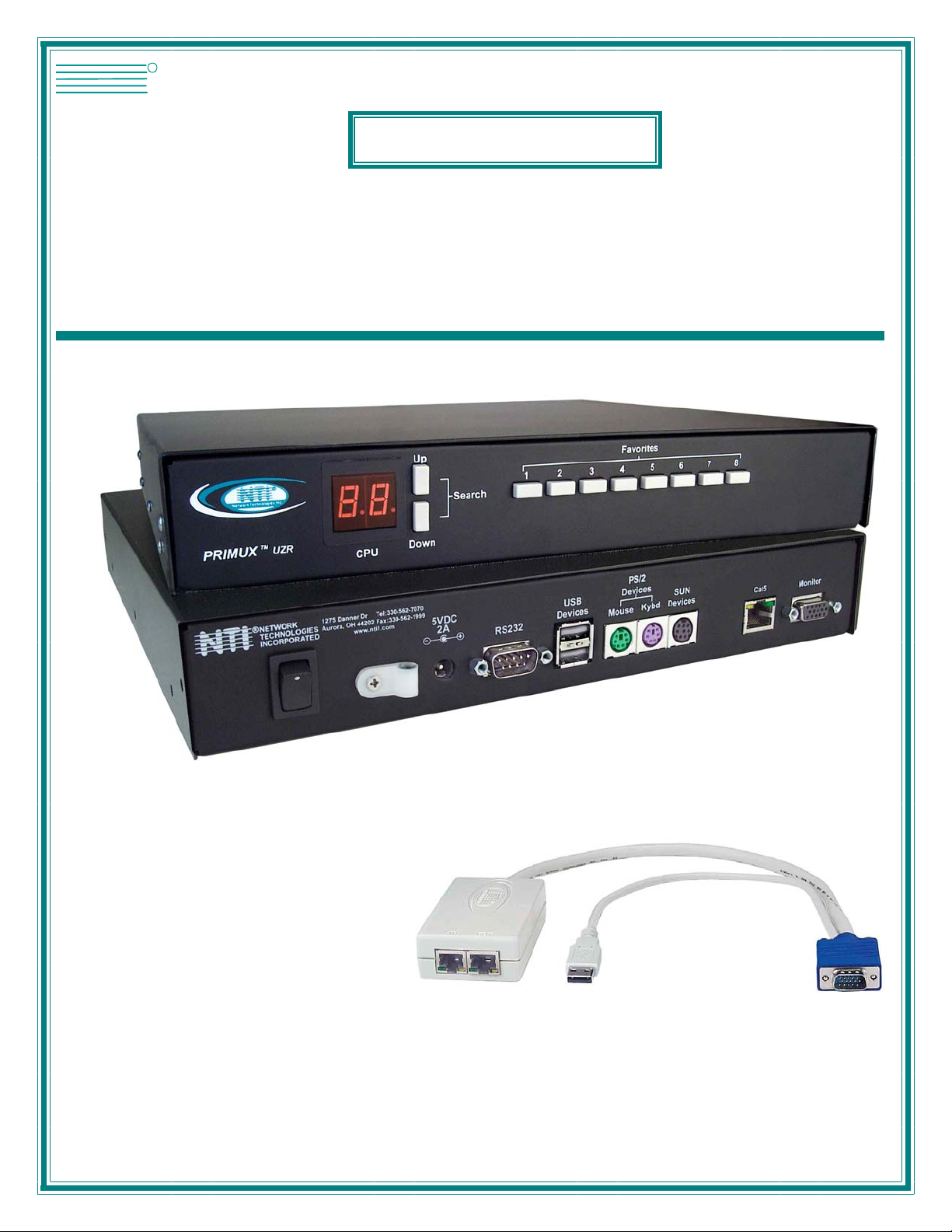
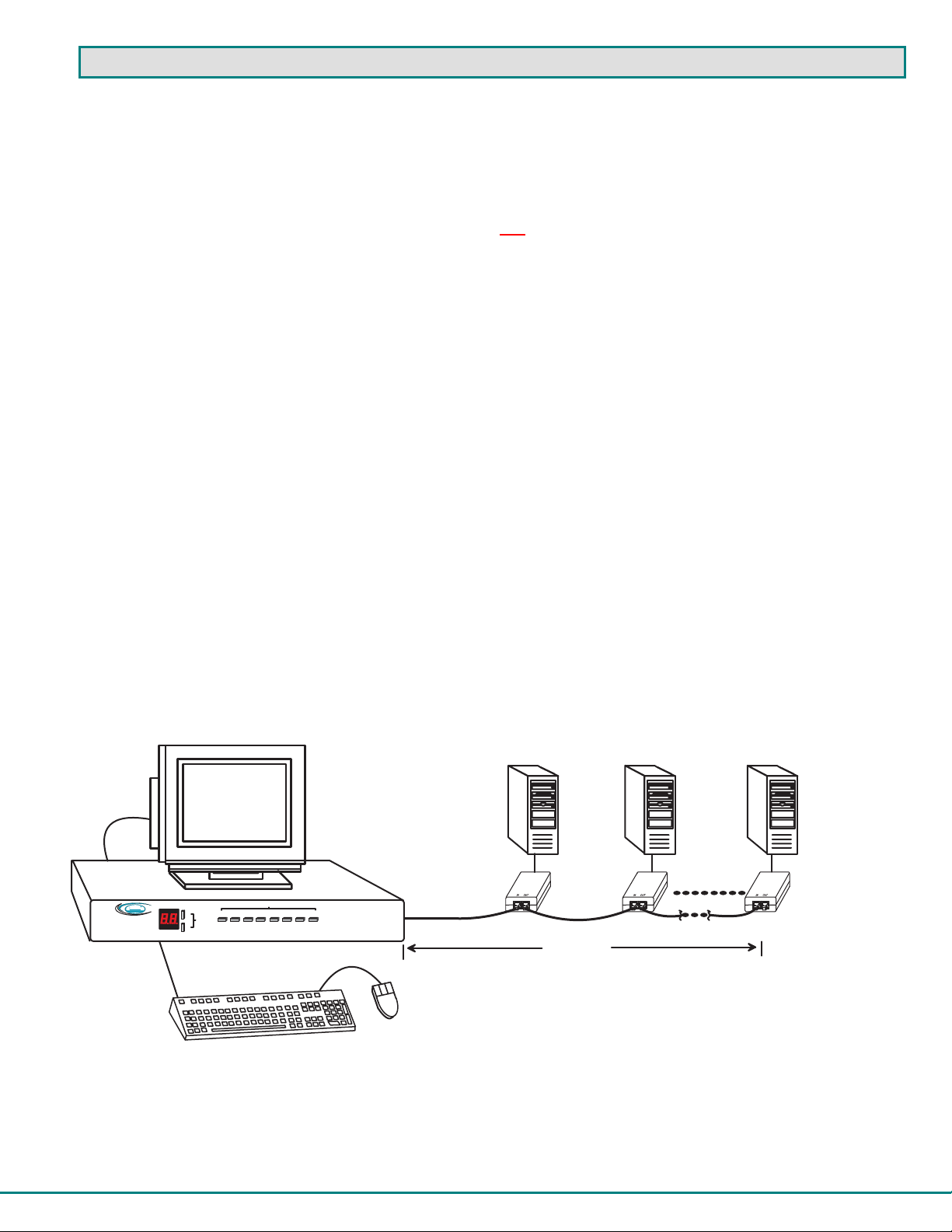
The PRIMUX CAT5 KVM System (PRIMUX) is designed to enable the relocation of a VGA monitor, PS/2 or USB keyboard, and
mouse from up to 64 PS/2, SUN, or USB CPUs by as much as 1000 feet. The PRIMUX is comprised of one PRIMUX-UZR User
Station and at least one Host Adapter (HA-PS2, HA-USB, or HA-SUN) connected to a CPU to be controlled by the user. The
PRIMUX-UZR User Station supports PS/2 and USB user keyboard and mouse (devices). This manual describes the installation
and use of both components.
The PRIMUX Host Adapter and User Station are interconnected with either CAT5 Unshielded Twisted Pair (UTP) or Shielded
Twisted Pair (STP) cable, CAT5e cable, or CAT6 cable.
The PRIMUX Series CAT5 KVM System is extremely simple to install and has been thoroughly tested to insure reliable
performance. Through the use of CAT5, CAT5e, or CAT6 cable it is possible to economically increase the flexibility of a computer
system. Here are some of the features and ways this can benefit any workplace:
• Allows the placement of a monitor, keyboard, and mouse in a location where only these parts are needed without having
the CPU there too, taking up valuable space
• Allows any PS/2, USB, or SUN CPU to be accessed by a remote user (up to 1000 feet away)
• Additional RJ45 port on the Host Adapter allows the daisy-chaining of up to 64 Host Adapters providing user access to
up to 64 CPUs
• Control up to 64 CPUs from one keyboard, mouse, and monitor without "spaghetti" wiring
• Compatible with XGA, VGA, and SVGA systems
• Provides crisp and clear resolution up to 1024x768 /60Hz @ 1000 feet (using CAT5 UT P cable- see pg 35 for details)
• Video quality adjustment is automatic providing optimum image quality
• Allows for future expansion- buy what is needed now, add more later as desired
Supported Operating Systems
The PRIMUX is compatible with:
• Win9x • WinMe • Solaris
• WinNT • WinXP • MAC OS9.x , OSX
• Win2K • Linux 7.x, 8.0 • Others
Materials
Materials Supplied with this kit:
• NTI PRIMUX-UZR User Station
• 120VAC or 240VAC @ 50 or 60Hz -5VDC/2A AC Adapter
• Line cord, country specific
• Terminating Plug
• PRIMUX CDROM w/ Owner's Manual and Quick Start Guide (pdf files)
• Quick Start Guide (Printed)
Materials Not Supplied, but REQUIRED:
• NTI HA-PS2 PS/2 Host Adapter / HA-USB USB Host Adapter / HA-SUN Host Adapter (see pg. 4)
• CAT5/5e/6 unshielded twisted-pair cable(s) terminated with RJ45 connectors wired straight thru- pin 1 to pin 1, etc. (see pg.
35 for proper EIA/TIA 568B wiring method)
• A null modem cable will be required for future software updates (see specification on page 36).
Cables can be purchased from Network Technologies Inc by calling 800-RGB-TECH (800-742-8324) or (330)-562-7070 or by
visiting our website at www.networktechinc.com.
1
Page 6
-
+
N T I
H A - P S 2 ( P S / 2 H o s t A d a p t e r )
( H o s t A d a p t e r s o l d s e p a r a t e l y )
N e t w o r k T e c h n o lo g i e s I n c
P R I M U X
1
2
3
F r o n t V i e w o f P R I M U X - U Z R ( U s e r S t a t i o n )
R
T M
U Z R
C P U
U p
S e a r c h
D o w n
F a v o r i t e s
7654321
8
R e a r V i e w o f P R I M U X - U Z R ( U s e r S t a t i o n )
5 V D C
2 A
R S 2 3 2
U S B
D e v i c e s
M o u s e
P S / 2
D e v i c e s
K y b d
S U N
D e v i c e s
N T I
1 1 a
R
N E T W O R K
T E C H N O L O G I E S
I N C O R P O R A T E D
C a t 5
1 2 7 5 D a n n e r D r
A u r o r a , O H 4 4 2 0 2
1 1 b
T e l : 3 3 0 - 5 6 2 - 7 0 7 0
F a x : 3 3 0 - 5 6 2 - 1 9 9 9
w w w . n t i 1 . c o m
M o n i t o r
+
4
5
6
7
8
9
1 0
1 1
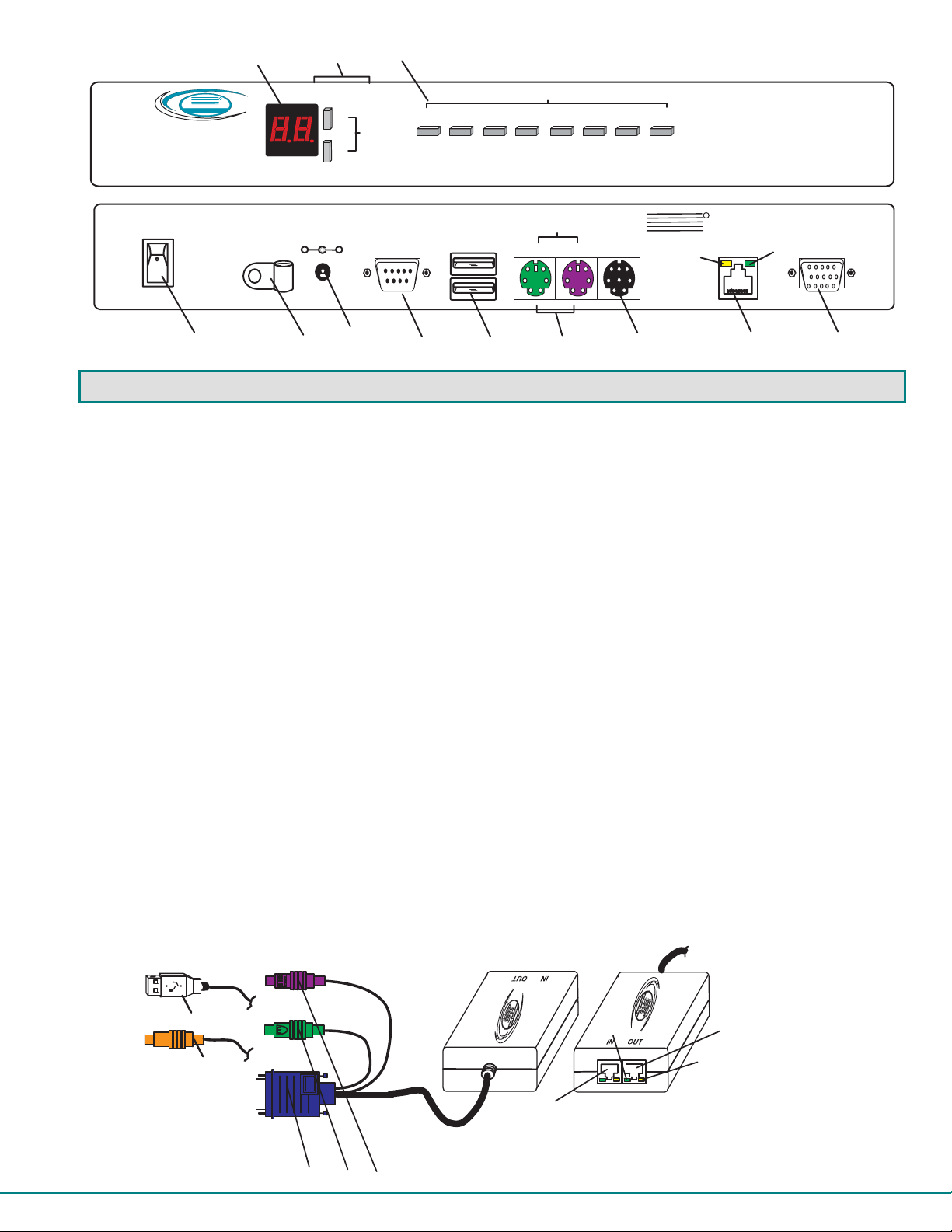
FEA TURES AND FUNCTIONS
1. LED Display- for visual indication of which Host Adapter the user is connected to
2. Search Buttons- to enable manual search for desired Host Adapter connection
3. Favorite Buttons- programmable buttons to quick selection of specific Host Adapters
4. Power Switch- to turn the User Station ON an OFF
5. Cable Clamp- to secure the cable from the AC adapter
6. 5VDC 2A- 3.5mm power jack- for connection of AC adapter
7. RS232- DB9 male- serial communication port for updating firmware
8. USB Devices- USB Type A female- for connection of USB user devices (keyboard and mouse)
9. PS/2 Devices- green and purple 6mD females- for connection of PS/2 type mouse (green) and keyboard (purple)
10. SUN Devices- black 8mD female- for connection of SUN mouse and keyboard
11. Cat5 - RJ45 female- for connection of CAT5 cable between Host Adapter and User Station
11a. Yellow LED- power indicator- illuminates when power has been supplied to the unit
11b. Green LED- traffic indicator- illuminates when there is communication between the User Station and Host
Adapters.
12. Monitor- for connecting the video monitor
1 2
13. Video Connector- blue 15HD male- for connecting to the video port on the CPU
14. Mouse Connector- green male 6 miniDIN (HA-PS2 only)- for connecting to the mouse port on a PS2 CPU
15. Keyboard Connector- purple male 6 miniDIN (HA-PS2 only)- for connecting to the keyboard port on a PS2 CPU
15a. Device Connector- male USB Type A (HA-USB only)- for connecting to a device port on a USB CPU
15b. Device Connector- orange male 8 miniDIN (HA-SUN only) - for connecting to the device port on a SUN CPU
16. Cat5- RJ45 female- for connection of CAT5 cable between daisy-chained Host Adapters
( F r o n t V i e w )
1 5 a
1 5 b
1 6
1 3 1 4 1 5
2
1 1 b
( R e a r V i e w )
1 1
1 1 a
Page 7
PREPARATION FOR INSTALLATION
r
• Choose a location for the User Station such that cables from the keyboard, mouse, and monitor will reach it.
• The CAT5 cables must be run between the locations where the Host Adapter will be connected and User Station is
positioned. Be careful to route the cables away from any sources of magnetic fields or electrical interference that might
reduce the quality of the signal (i.e. AC motors, welding equipment, etc.) .
NOTE: The installer must ensure that all CAT5 cable between the Host Adapter and User Station, and between each Host
Adapter (if more than one) is of the straight-through type and not crossed.
• A 120V or 240V electrical supply (depending on the AC adapter being used) must be provided close enough to the position of
the User Station to plug the AC adapter into.
• All cables should be installed such that they do not cause stress on their connections to the equipment. Extended lengths of
cable hanging from a connection may interfere with the quality of that connection. Secure cables as needed to minimize
this.
• Properly shut down and disconnect the power from the CPU and devices to be extended. If other equipment is involved
whose connections are being interrupted, be sure to refer to the instruction manuals for that equipment for proper
disconnection and re-connection procedures before proceed ing.
Definitions
Segment A single or series of CAT5 cable(s) from one user station to one or more Host Adapter(s)
that are daisy-chained together. A segment begins with the user station and ends with the
last Host Adapter in the daisy chain.
Master ID A unique number assigned by the administrator to a PRIMUX segment. It is used to identify
parts that have been configured by the master authority, particularly Host Adapters that
attempt to join the segment.
Master
Authority
String A set of characters, A-Z, 0-9, upper or lower case
Integer Any whole number (1,2,3…)
Unique ID Number identifying a Host Adapter to the master authority of a segment.
The ultimate controlling authority in a segment (i.e. the master authority establishes the
unique I.D. for each Host Adapter). The master authority is part of the User Station.
P R I M U X
Ne t w or k Te c hn o lo g ie s In c
V G A
M u l t i - S c a n
M o n i t o r
R
N T I
U p
T M
U Z R
S e a r c h
D o w n
C P U
F r o n t V i e w o f P R I M U X - U Z R
F a v o r i t e s
7654321
8
S U N K e y b o a r d / M o u s e
C A T 5 C a b l e
P S / 2 ,
U S B ,
O R S U N
H o s t
A d a p t e r
C A T 5 C a b l e
U P T O 1 0 0 0 '
Figure 1- Typical Application
3
P S / 2 ,
U S B ,
O R S U N
H o s t
A d a p t e r
C P U 6 4C P U 2C P U 1
P S / 2 ,
U S B ,
O R S U N
H o s t
A d a p t e
C A T 5 C a b l e
Page 8
INSTALLATION
H A - P S 2
The Host Adapter
The PRIMUX HA Host Adapter is designed to support PS/2, SUN, and USB CPUs. For PS/2 CPUs use HA-PS2, for SUN
CPUs use HA-SUN, and for USB CPUs use HA-USB. Before installing or removing a Host Adapter, power down the CPU to be
connected/disconnected and disconnect the power cord from the CPU.
CAUTION!
CONNECTING OR DISCONNECTING CABLES
DAMAGE MAY OCCUR TO THE
.
CPU
AND HOST ADAPTER IF POWER IS NOT DISCONNECTED BEFORE
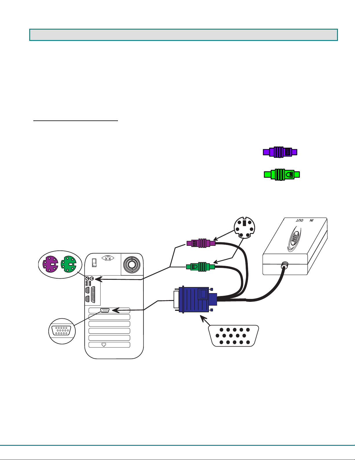
Installation of a PS/2 CPU
Plug the cables of the HA-PS2 Host Adapter into the back of the CPU after disconnecting the power cord from the CPU.
(See Fig. 2.)
a) Connect the purple 6 pin mi niDIN cable end with the keyboard symbol
on it to the keyboard port on the back of the CPU.
PS/2 Keyboard
b) Connect the green 6 pin miniDIN ca ble end with the mouse symbol
on it to the mouse port on the back of the CPU.
PS/2 Mouse
c) Connect the blue 15HD cable end to the VGA port on the back of the CPU.
6 m i n i D I N
m a l e c o n n e c t o r s
6 p i n m i n i D I N
f e m a l e c o n n e c t o r s
p u r p l e - k e y b o a r d
g r e e n - m o u s e
1 5 H D f e m a l e
v i d e o c o n n e c t o r
R e a r V i e w o f P S / 2 C P U
Figure 2- Connect a HA-PS2 Host Adapter to a PS/2 CPU
1 5 H D m a l e
v i d e o c o n n e c t o r
( F r o n t V i e w )
4
Page 9
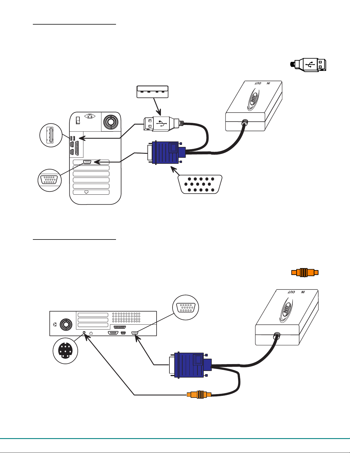
Installation of a USB CPU
H A - U S B
H A - S U N
Plug the cables of the HA-PS2 Host Adapter into the back of the CPU after disconnecting the power cord from the CPU. (See
Fig. 3.)
a) Connect the cable with the USB T ype A male c able end on it to a USB Type A female port on the back of the
CPU.
b) Connect the blue 15HD cabl e end to the video connector on the back of the CPU.
U S B T y p e A m a l e
U S B T y p e A
d e v i c e p o r t
1 5 H D f e m a l e
v i d e o c o n n e c t o r
R e a r V i e w o f U S B C P U
1 5 H D m a l e
v i d e o c o n n e c t o r
Figure 3- Connect a HA-USB Host Adapter to a USB CPU
Installation of a SUN CPU
USB Devices
( F r o n t V i e w )
Plug the cables of the HA-SUN Host Adapter into the back of the CPU after disconnecting the power cord from the CPU.
(See Fig. 4.)
a) Connect the orange 8 pin miniDIN cable end on it to the devices port on the back of the CPU.
b) Connect the blue 15HD cable end to the VGA port on the back of the CPU.
R e a r V i e w o f S U N C P U
1 5 H D f e m a l e
v i d e o c o n n e c t o r
8 p i n m i n i D I N
f e m a l e c o n n e c t o r
o r a n g e - d e v i c e s
SUN Devices
( F r o n t V i e w )
Figure 4- Connect a HA-SUN Host Adapter to a SUN CPU
FYI: The HA-SUN Host Adapter does not provide startup key support for SUN CPUs.
5
Page 10
H A - P S 2
( R e a r V i e w )
C A T 5 C a b l e
t o U s e r S t a t i o n
C a b l e t o C P U
T e r m i n a t i n g
P l u g ( S u p p l i e d )
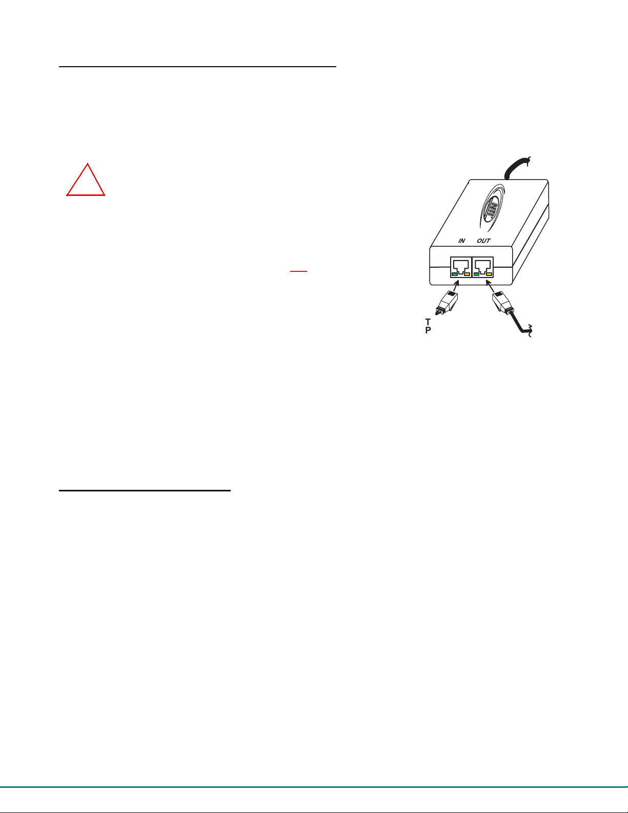
Connecting the CAT5 cable to the Host Adapter
Connect CAT5 cable to the “OUT” port on the Host Adapter. (See Fig. 5.) When properly inserted the cable end should snap into
place. Also be sure to insert the Terminating Plug into the "IN" port on the Host Adapter if this is the only Host Adapter in the
segment. Otherwise, see "Daisy-Chained Host Adapters" on page 9 to add more Host Adapters to the segment.
NOTE: If an RJ45 wall outlet is being used, connect the other end of th e exten sion cable
to the RJ45 wall outlet.
!
WARNING: Never connect the PRIMUX Host Adapter to an Ethernet card,
Ethernet router, hub or switch or other Ethernet RJ45 connector of an Ethernet
device. Damage to devices connected to the Ethernet may result.
NOTE: The installer must ensure that all CAT5 cable between the Host Adapter
and User Station is of the straight-through type and not crossed.
Figure 5- Connect CAT5 cable to Host Adapter
The User Station
The PRIMUX-UZR User Station can be used with either PS/2 devices or USB devices.
NOTE: If the user keyboard connected is PS/2 (6mD connector), then the mouse must also be PS/2. If the user
keyboard is USB (USB Type A connector), then the mouse must also be USB.
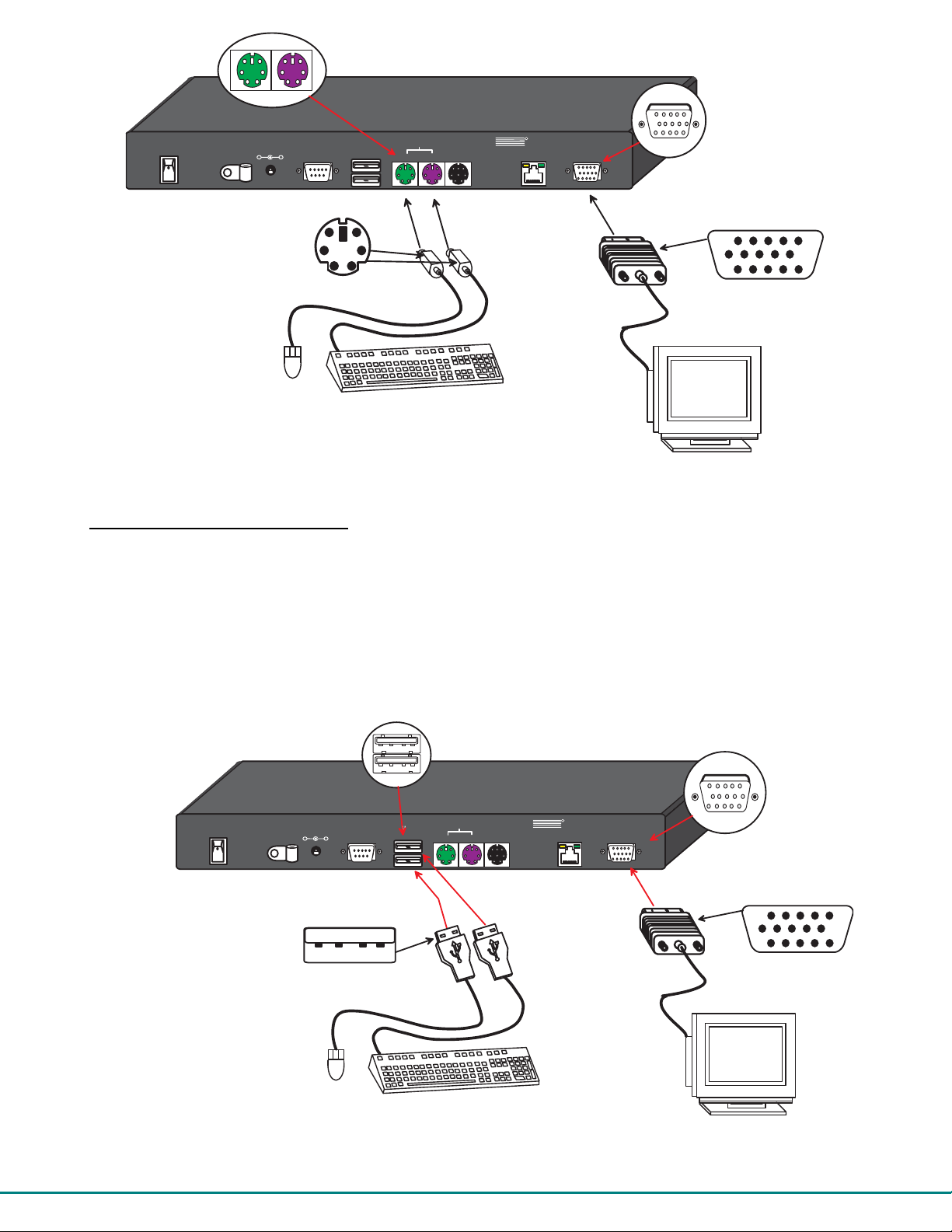
Installation with PS/2 devices
1. Position the User Station such that the CAT5 cable, the monitor cable, device cables, and the AC adapter power connector
can each reach the User Station without cable strain.
2. Connect the monitor cable to the female 15HD video connector on the User Station.
3. Connect the PS/2 device(s) to the User Station (see Fig. 6).
a. Connect the keyboard to the purple female 6 pin miniDIN connector on the User Station.
b. Connect the mouse to the green female 6 pin miniDIN connector on the User Station.
6
Page 11
-
+
6 p i n m i n i D I N
-
+
f e m a l e c o n n e c t o r s
R e a r V i e w o f
P R I M U X - U Z R U s e r S t a t i o n
R
P S / 2
5 V D C
2 A
R S 2 3 2
U S B
D e v i c e s
M o u s e
D e v i c e s
S U N
D e v i c e s
K y b d
N T I
N E T W O R K
T E C H N O L O G I E S
IN C O R P O R A T E D
C a t 5
+
6 m i n i D I N
m a l e c o n n e c t o r s
P S / 2
M o u s e
P S / 2 K e y b o a r d
1 2 7 5 D a n n e r D r
A u r o r a , O H 4 4 2 0 2
M o n i t o r
w w w . n t i1 . c o m
T e l :3 3 0 - 5 6 2 - 7 0 7 0
F a x : 3 3 0 - 5 6 2 - 1 9 9 9
Figure 6- Connect the Extended PS/2 components to the User Station
1 5 H D f e m a l e
v i d e o c o n n e c t o r
1 5 H D m a l e
v i d e o c o n n e c t o r
V G A
M u l t i - S c a n
M o n i t o r
Installation with USB devices
1. Position the User Station such that the CAT5 cable, the monitor cable, device cables, and the AC adapter power connector
can each reach the User Station without cable strain.
2. Connect the monitor cable to the female 15HD video connector on the User Station.
3. Connect the USB device(s) to the User Station (see Fig. 7).
a. Connect the keyboard to a USB Type A female connector on the User Station.
b. Connect the mouse to the other USB Type A female connector on the User Station.
U S B T y p e A f e m a l e
d e v i c e p o r t s
P R I M U X - U Z R U s e r S t a t i o n
P S / 2
5 V D C
2 A
R S 2 3 2
U S B
D e v i c e s
M o u s e
D e v i c e s
S U N
D e v i c e s
K y b d
+
U S B T y p e A m a l e
N T I
R
N E T W O R K
T E C H N O L O G I E S
IN C O R P O R A T E D
C a t 5
1 5 H D f e m a l e
v i d e o c o n n e c t o r
T e l: 3 3 0 -5 6 2 - 7 0 7 0
1 2 7 5 D a n n e r D r
F a x : 3 3 0 - 5 6 2 - 1 9 9 9
A u r o r a , O H 4 4 2 0 2
w w w . n t i 1 .c o m
M o n i t o r
1 5 H D m a l e
v i d e o c o n n e c t o r
U S B
M o u s e
U S B K e y b o a r d
Figure 7- Connect extended USB components to the User Station
7
V G A
M u l t i - S c a n
M o n i t o r
Page 12
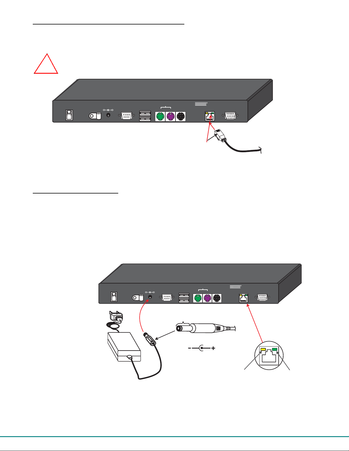
Connecting the CAT5 cable to the User Station
-
+
B a r r e l
( I n s i d e
b a r r e l )
( O u t s i d e
b a r r e l )
P o w e r C o n n e c t o r
2 . 1 m m x 5 . 5 m m F e m a l e
5 V D C @ 2 . 0 A O U T P U T
G r e e n C o m m u n i c a t i o n L E D
Y e l l o w P o w e r L E D
5 V D C
A C
A D A P T E R
R e a r V i e w o f P R I M U X - U Z R
C a t 5
M o n i t o r
S U N
D e v i c e s
P S / 2
D e v i c e s
M o u s e
K y b d
R S 2 3 2
U S B
D e v i c e s
5 V D C
2 A
-
+
N E T W O R K
T E C H N O L O G I E S
IN C O R P O R A T E D
T e l: 3 3 0 - 5 6 2 - 7 0 7 0
F a x : 3 3 0 -5 6 2 -1 9 9 9
1 2 7 5 D a n n e r D r
A u r o r a , O H 4 4 2 0 2
w w w . n ti 1 .c o m
N T I
R
+
R e a r V i e w o f P R I M U X - U Z R U s e r S t a t i o n
Make sure the CAT5 cable has been installed in accordance with the “Preparation for Installation” instructions on pag e 3.
Connect the CAT5 cable to the “Cat 5” port on the User Station. (See Fig. 8.) When properly inserted the CAT5 cable end should
snap into place.
WARNING: Never connect the PRIMUX-UZR User Station to an Ethernet card, Ethernet router, hub or switch
or other Ethernet RJ45 connector of an Ethernet device. Damage to devices connected to the Ethernet may
!
result.
R e a r V i e w o f P R I M U X - U Z R U s e r S t a t i o n
R
P S / 2
5 V D C
2 A
R S 2 3 2
U S B
D e v i c e s
M o u s e
D e v i c e s
S U N
D e v i c e s
K y b d
N T I
N E T W O R K
T E C H N O L O G I E S
IN C O R P O R A T E D
C a t 5
+
1 2 7 5 D a n n e r D r
A u r o r a , O H 4 4 2 0 2
w w w . n t i 1 . c o m
M o n i t o r
T e l : 3 3 0 -5 6 2 - 7 0 7 0
F a x :3 3 0 - 5 6 2 - 1 9 9 9
R J 4 5 m a l e
C A T 5 c o n n e c t o r
C A T 5 c a b l e
t o M a t r i x S w i t c h
Figure 8- Connect CAT5 cable to User Station
NOTE: If an RJ45 wall outlet is being used, connect the other end of the extension cable to the RJ45 wall outlet.
Power Up for the first time
Note: The user devices, monitor, and CAT5 cable should already be connected before powering up the User Station
1. Connect the AC adapter power connector to the 5VDC port on the User Station (see Fig. 9). Plug the AC adapter into a
power outlet. The yellow LED on the RJ45 connector of the User Station should illuminate, indicating that a proper power
connection has been made to it.
2. Re-connect the power cord to the CPU.
FYI: The Host Adapter is powered by the CPU.
3. Power up the monitor.
.
Figure 9- Connect the AC adapter to the User Station
4. With the User Station and Host Adapter connected via CAT5 cable, refer to "Using the PRIMUX CAT5 KVM Switch" on
page 10.
FYI: The green LED on each RJ45 connector will illuminate anytime data traffic is passing between the Host Adapter and
User Station, indicating proper CAT5 cable connection and communication. (See F ig. 9)
8
Page 13
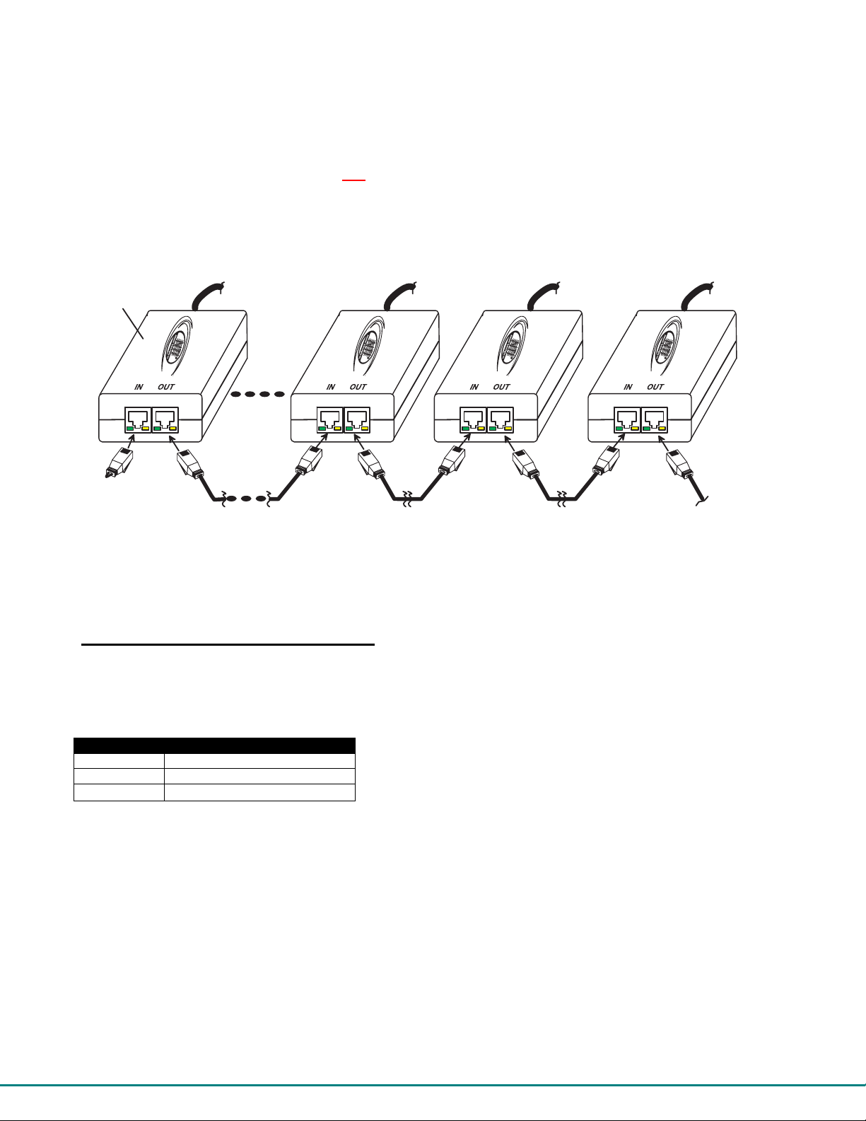
Daisy-Chained Host Adapters
H A - P S 2
H A - P S 2
H A - P S 2
H A - P S 2
Up to 64 Host Adapters can be connected in a daisy-chain to a create a segment of CPUs that are controlled by a single user from
a User Station. The first Host Adapter is connected to the User Station via the "OUT" port. The additional Host Adapters in the
segment will have CAT5 cable going from their "OUT" port to another Host Adapter's "IN" port to enable communications between
the user and each CPU in the system, as shown in Fig. 10. A Terminating Plug must be installed in the "IN" port of the last
Host Adapter in the segment.
NOTE: The installer must ensure that all CAT5 cable terminations between each Host Adapter are of the straight-through
type (pin 1 to pin 1, pin 2 to pin 2, etc.) and not crossover.
NOTE: The total length of the CAT5 cable from the User Station to the last Host Adapter in th e daisy-chain mu st n ot
exceed 1000'.
L a s t H o s t
A d a p t e r i n
( R e a r V i e w )
C a b l e t o C P U 6 4
( R e a r V i e w )
C a b l e t o C P U 3
( R e a r V i e w )
C a b l e t o C P U 2
( R e a r V i e w )
C a b l e t o C P U 1
t h e s e g m e n t
T e r m i n a t i n g
P l u g ( S u p p l i e d )
C A T 5 C a b l e
C A T 5 C a b l e
C A T 5 C a b l e
C A T 5 C a b l e
C A T 5 C a b l e
t o U s e r S t a t i o n
Figure 10- Daisy-chained Host Adapters
Adding a Host Adapter to a segment
When adding a Host Adapter to a segment, whether at the end, or inside the chain (between two other Host Adapters connected
together), the administrator must follow some simple steps:
1. Make sure the Host Adapter being connected to a CPU is the proper type for the CPU.
CPU TYPE HOST ADAPTER MODEL
PS/2 HA-PS2
USB HA-USB
SUN HA-SUN
2. Determine what name the Host Adapter will be identified as in the Host Adapter list (should be unique to all other known hosts
in the segment).
3. Follow the installation instruction on page 3 for Host Adapters and for above for Daisy-Chained Host Adapters.
FYI: A Host Adapter can be added to the last Host Adapter in the chain, or between two existing Host Adapters.
NOTE: Do NOT attach a Host Adapter to a CPU or disconnect a Host Adapter from a CPU wh ile th e CPU is connected to
power. Disconnect the power cord first, then connect or disconnect the Host Adapter. Failure to do so may result in
damage to the Host Adapter or CPU.
4. Once the installation procedure is complete the connected CPU can be powered up.
5. This Host Adapter will be auto discovered by the master authority. It will identify itself as "(NEW PS2 HA)" , "(NEW USB
HA)", or "(NEW SUN HA)".
6. The administrator should assign a unique name to the Host Adapter (see page 23)
7. All users will have default access to the new Host Adapter unless the Administrator configures the access otherwise (see
page 26).
8. Once access controls have been set, the administrator should verify the security access to the new Host Adapter.
9
Page 14

USING THE PRIMUX CAT5 KVM SWITCH
The PRIMUX CAT5 KVM System is designed to enable a user to control as many as 64 PS/2, USB, and SUN CPUs (any mixture
of each) from a single User Station as much as 1000 feet from the farthest CPU. Control is achieved through the use of either
the keypad on the front panel or On Screen Display (OSD) Menus. Access to one or more CPUs is determined by the security
configuration of the PRIMUX as set by the administrator. Once user access limitations are defined, the user can select which
CPU to connect to using either the OSD menu, the "Search" buttons on the front of the User Station, or quickly make a selection
after programming the "Favorite" buttons.
Hot Plugging
The PRIMUX-UZR is designed to emulate the presence of a mouse and keyboard whenever the PRIMUX-UZR is powered up.
As a result, the keyboard and mouse may be hot-plugged from the User Station at any time without causing a CPU error.
Note: Device types cannot be changed when hot-plugging. If the device type is changed (i.e. from PS/2 to USB), the
PRIMUX-UZR must be power cycled (turned OFF, then ON again) for the device to work properly.
Note: Both devices must be either PS/2 or USB. There cannot be one of each connected to the User Station.
The PRIMUX Host Adapter may also be hot-plugged to a CPU, provided the CPU and the operating system supports device hotplugging. (Operating systems known to support hot-plugging include Windows 2000 SP3 an d higher, Windows XP, and Linux
2.6 and higher. )
CAT5 cables can be hot plugged. If the CAT5 cable is disconnected, the User Station will continue to monitor all Host Adapters
in the Host Adapter List.
FYI: Once a Host Adapter is selected by the User Station it will stay connected or attempt to connect forever if the
selected Host Adapter is powered OFF or the CAT5 cable is disconnected. To properly remove a Host Adapter, the user
must delete it from the Host Adapter List (page 23).
Hot plugging a Host Adapter to an NTI VOPEX splitter is not recommended. If communication is lost, send a "Reset Host"
command (page 23 ) from the User Station to restore communication.
Initial Startup
After installing the User Station and one or more Host Adapters as described on pages 3-6, when first applying power the user
will be prompted to supply a Master ID number. The Master ID number is any number from 0 to 65523. This number will be the
Master ID of the segment. All Host Adapters added to the segment will be configured with this number to become part of the
segment.
Note: The PRIMUX User Station cannot be used to control anything until the Master Identification number has been
properly set.
Note: If more than one segment will be configured, be sure to assign a unique Master ID nu mber to each.
Following assignment of the Master ID number, the NEW_USER1 will be automatically logged-in and the Command Mode me nu
will appear. By default, access is given to all Host Adapters and their connected CPUs, and Scan Mode will scan all connected
CPUs.
User Rights vs. Administrator Rights
Before continuing, the user should consider what action is going to be taken. The User and Administrator of the PRIMUX CAT5
KVM system have different roles and control over what the PRIMUX does.
Administrator Rights Include:
¾ Change the Administrator Password
¾ Assign, edit, and remove user names and passwords
¾ Define user access rights to CPUs in the segment
¾ Adding and configuring Host Adapters in the segment
¾ Configure operating parameters of the User Station
¾ Update DDC information between the monitor an d CPUs
FYI: Users can be given full administrative access rights by the administrator.
10
Page 15

User Rights Include:
¾ The ability to connect the user's keyboard, mou s e, and monitor to CPUs (only those CPUs that have been granted
access by the administrator).
¾ The ability to enable/disable Scan Mode
¾ The ability to change the sorting method of Host Adapters by index number or alphabetically
Administrator Login and Password
To login as the administrator, press <L> to logout as NEW_USER1 and the login splash screen will appe ar. While holding down
the <Shift> key, enter an administrator name and default password:
administrator names = ROOT or ADMINISTRATOR (either can be used)
default administrator password = NTI
With a successful login, the administrator can setup additional users (see page 24).
FYI: The User Station can be configured to Autologon a specific user (page 29) with each User Station power up or have
a Login splash screen appear for the user to login to the User Station. The administrator can also configure the User
Station to autoconnect a user to a specific Host Adapter at logon by configuring the L ogon Host and Action on Logon in
the Edit User menu (page 25). For more on setting up users, see page 25.
Setup Host Adapter(s)
No initial configuration of the Host Adapter is required for it to be identified by the User Station in the segment. Once discovered
it appears in the segment, and the Master Authority assigns the Host Adapter its Unique ID value. This value is used to
¾ set its identity for the security allow/deny access attribute (page 26)
¾ set its identity in the list of Host Adapters/CPUs that can be scanned in Scan Mode (page 19)
The Unique ID is stored in the Host Adapter and saved there, even if power is removed.
Quick Connect
From the Command Mode menu, to make connection to any Host Adapter in the segment,
press <G> followed by the index number (see pg 14) of the desired Host Adapter,
press <Enter> to select it,
press <Enter> again to connect to it.
-OR-
use the mouse to select the desired Host Adapter to connect to and click on it to connect.
Press <X> or <Esc> to exit Command Mode and use the connected CPU connected to the selected Host Adapter.
Press <Ctrl> + <`> to return to Command Mode (see pg 13).
Change the Default Administrator Password
Once the administrator is logged in, it is recommended that the the administrator change the default administrator password.
To change the administrator password :
- Press A (Administration Menu) - E (Edit Menu) - U (Edit User Menu) - P (Change Root Password)
- Enter the current password (default is "NTI")
- Enter the new password (case sensitive, 16 characters maximum, alphanumerc)
- Press < Enter>
- Re-enter to confirm the new password
- Press < E nter> to finish, or <Tab> to enter the password again.
Note: In the event the password is forgotten, contact NTI for instru ction on how to reset the password to the default
"NTI".
FYI: When the password is changed for user ROOT , it automatically changes for user ADMINISTRATOR as well.
11
Page 16

Standards of Operation
Throughout this manual, various standards of operation apply to th e men us used to control and operate the PRIMUX.
• OSD menus can be navigated by the up and down arrows on the keyboard, as well as the <Page Up>, < Page Down>,
<Home>, and <End> keys.
- T he up and down arrows increment/decrement one line item at a time
- <Page Up> and <Page Down> increment/decrement by one page at a time
- <Home> will jump to the beginning of the list
- <End> will jump to the end of the list.
• The scroll bar in a list can be used by clicking on the corresponding up and down arrow above and below the scroll
bar.
• The mouse wheel may be used to move the selection bar
• Functions that are "Administrator Only" are also available to users having administrative rights (see page 25).
• Placing the mouse over a listed Host Adapter highlighting the listed item with a blackened background "selects" the
Host Adapter. Clicking on it while in Command Mode will connect to that Host Adapter.
• Available functions will have white characters with one red character. The background of available functions will
become green when the mouse pointer is positioned over the function. Functions that are not available will be
transparent.
• When pressing a letter is called for to select a function, press either the corresponding key on the keyboard or use
the mouse to select the function.
• To exit any menu , press < Esc> or <X> on the keyboard or click on "Esc" in the menu.
• When "+" is shown between keystrokes, it indicates a chorded sequence (press and hold the keys consecutively
until all keys in the sequence are pressed). I.e. <Ctrl>+<`> is a chorded sequence to enter Command Mode.
• When "-" is shown between keystrokes, it indicates to press the keys consecutively (press and release one at a time)
• Press <F10> to retu rn directly to the Command Mode menu
N T I
N e t w o r k T e c h n o lo g i e s I n c
P R I M U X
R
T M
U Z R
C P U
U p
S e a r c h
D o w n
F a v o r i t e s
7654321
8
Figure 11- PRIMUX-UZR front panel
Keypad Control
The keypad on the front panel of the PRIMUX User Station enables a user to quickly set the User Station to connect to the desired
CPU. Two seven-segment LEDs illuminate to show the index number of the Host Adapter the user is connected to. The Up and
Down buttons enable the user to search for the desired CPU. The Favorite buttons, 1-8, can be programmed for quick selection
of the most commonly connected CPUs. (See Fig. 11) By default, the Favorite buttons 1-8 are pre-programmed to connect to
Host Adapters 1-8.
To program a Favorite button,
- Use the Search buttons to select the desired Host Adapter index number to connect with (or use OSD Command
Mode).
- With the index number in the LED display, press and hold the Favorite button to be associated with it for at least 2
seconds. The LED will blink when the selection is remembered and until the Favorite button is released.
- When this button is pressed, the User Station will immediately connect to the selected Host Adapter.
- Repeat for each Favorite button to be programmed.
Note: Favorite buttons are not available when PRIMUX is mounted in a RACKMUX-15/17-PRIMUX drawer.
Security
The PRIMUX CAT5 KVM System is designed with security to prevent unauthorized use of the CPUs connected as determined by
the administrator. Up to 16 users may be given access to the system, each with individual limitations of use. Only the
administrator or user with administrative privileges can activate or deactivate the security features on each user port. Finally, the
administrator can set a maximum idle time value after which the current user will be logged out and the login splash screen
displayed again. The current security status, idle time out, and scan dwell time are all saved and will be restored whenever
power to the User Station is cycled OFF, then ON. To reset the administrator’s password call NTI and have the device serial
number of the PRIMUX User Station available.
12
Page 17

Administrator Login
To access the OSD menu Command Mode from the keyboard press the <Ctrl> + <`> (accent key). (An additional alternate OSD
key may be defined, see page 31) The User Login screen will automatically appear on the monitor. In order to configure the
PRIMUX, when the PRIMUX is powered ON, the administrator can login with a proper user name and password. While holding
down the <Shift> key, enter the following;
administrator names = ROOT or ADMINISTRATOR (either can be used)
default administrator password = NTI
FYI: The names for the administrator cannot be changed.
Once logged-in, follow the instructions on pages 10 or 27 for changing the password. Once the password is setup, if it is lost or
forgotten the administrator will have to contact NTI for assistance on clearing the password and set it up again. The administrator
can setup each of the users (page 26) and the limitations of their use of the individual CPUs from within Administration Mode.
Autologin
By default, the user account NEW_USER1 has been configured to automatically login at power-up. The adminstrator ma y
reconfigure the User Station to autologin a different user (page 28) or have a Login splash screen appear at power-up requiring a
user to login, with or without a password). The autologin user uses CPUs listed in its Host Allow/Deny Access List as configured
by the administrator (page 26).
User Login
The administrator may configure the User Station to require each user to login using a predefined password to gain access rights
to CPUs and to the features in the OSD menus. Once logged in, the user may be directed to either a specific CPU (provided the
CPU is powered ON), or to the OSD menu where the user can decide what action is to be taken. The initial action (Action on
Logon- page 25) and whether or not to connect to a specific Host Adapter (Logon Host- page 25) will be configured b y the
administrator.
Once logged-in a user can use the Command Mode functions described bel ow a nd on page 14 to control the segment of CPUs
within the limitations as determined by the administrator.
Function Keystroke
Add a character to the user
name/password
Remove previous character from
the user name/password
Submit user name/password Enter or Tab
If the password submitted is incorrect, the user will
not be able to proceed.
If the password submitted is correct, the user will
either proceed to a CPU chosen by the
administrator and operate in Normal Mode, or
proceed to the Command Mode menu.
Figure 12- Login splash screen
A-Z, 0-9
Max. 16 characters
Backspace
User Access Functions
Command Mode
In order to control the User Station with the keyboard, Command Mode must be enabled. To enable Command Mode from the
keyboard:
(ACCENT
Press
All the status lights on the keyboard will illuminate to indicate that Command Mode is enabled. At this point, the Command Mode
menu will be displayed.
Ctrl
+
~
KEY)
`
`
13
Page 18

The Command Mode menu (see Fig. 13) lists all Host Adapters by name and index number. Only 8 Host Adapters are listed on
r
Adapter
r
the screen at a time. To view the other portions of the list, scroll using the arrow keys on the keyboard or use the mouse to click
on the arrows on the scroll bar in the OSD menu. When the Command Mode main menu is first displayed, the first Host Adapter
listed will be the Host Adapter the current user is connected to, followed by the next seven consecutively numbered ports.
(Alternatively the list may be sorted alphabetically- see Settings Menu on page 15 to tog gle sort method.) The names of
accessible Host Adapters are displayed with white characters. The access rights for the user logged-in may not include all Host
Adapters. Names of restricted access Host Adapters are displayed in blue.
An arrow to the left of an index number in the list indicates the Host Adapter the user is currently connected to. From left to right,
the columns display the following:
• Index Number
• Host Adapter Name
• Type of Host Adapter connected (PS2, SUN, or USB)
• CPU power status (where "p" means ON and " - " means OFF)
Mouse Cursor
FYI: A red hourglass will appear
near the upper right corner of the
OSD menu to indicate that the
screen is being refreshed. This
will occur after 5 seconds of
keyboard and mouse inactivity..
Index Numbe
Host Adapter Name
Arrow indicates currently
connected Host Adapter
Logged-in use
Commands for submenus
Figure 13- Command Mode main menu
The list below describes the command functions available from the keyboard within the OSD mode of control after entering into
Command Mode:
Selection Bar
Type of Host
CPU Power
Status
Mouse
Controls
Home
Page Up
Up One
Page Down
End
Function Keystroke
Select the previous Host Adapter Up Arrow
Select the next Host Adapter Down Arrow
Decrements the menu by 1 page (displays the previous 7 Host Adapters) Page Up
Increments the menu by 1 page (displays the next 7 Host Adapters)
Display first 8 Host Adapters and move selection bar to the first Home
Display last 8 Host Adapters and move selection bar to the last End
Press to toggle enable/disable Scan Mode S
Enter Settings Menu T
Find a Host Adapter (using name, comment, unique ID, index number) F
Enter Administration Mode (Administrator only- see page 20)
Display info for the selected Host Adapter/User Station I
Display Command Mode Help Menu H or F1
Go to - select Host Adapter by index number G
Search- select Host Adapter by name R
Page Down
A
14
Page 19

Function Keystroke
Connect to the highlighted Host Adapter Enter or Spacebar
Log Out the User/Administrator and disconnect from the Host Adapter
(The login screen will appear)
Exit Command Mode without logging out X or Esc
The mouse can also be used to control the User Station Command Mode.
• T he scroll wheel can be used to scroll through the Host Adapters list.
• T he mouse cursor can be moved to the any of the command fields where the user can click on
the left mouse button to select that function.
• Host Adapters listed on the scree n can b e selected by moving the cursor onto a Host Adapter.
• T o connect to a Host Adapter, click o n the sele cted Host Adapter.
• T o move through the Host Ad apter list, the scroll bar to the right of the list can be used by clicking the up and
down arrows.
Note: Exit Command Mode to enter Normal Mode and control the connected CPU. To exit Command Mode, press <Esc>
or click the “ESC” command on the screen with the mouse.
L
Scan Mode
To activate Scan Mode press <S> from the Command Mode menu.
Scan Mode enables the user to scan through selected Host Adapters and to have full device control of the connected Host
Adapter. From the Settings menu (below) the user can edit the list of Host Adapters that can be scanned. A Host Adapter is
skipped from the scan cycle if one of the following conditions is true:
• the Host Adapter is not in the scan list
• the user does not have access rights to the Host Adapter
When switching to a new Host Adapter the Host Adapter name is displayed by OSD for 5 seconds or until a ke y is press ed or the
mouse is moved, whichever comes first. The scan dwell time is programmable from 2 to 255 seconds (default time-out period is 5
seconds). When the user moves the mouse or types on the keyboard the scanned Host Adapter becomes active and scanning is
stopped. The switch will resume scanning after a period of user inactivity determined by the scan dwell time. See Settings Menu
below for configuring the scan dwell time.
Note: The keyboard and mouse must remain idle for the full scan dwell time befo re the switch selects the next active
Host Adapter.
Normal Mode
When the User Station is not in Command or Scan mode and the OSD control is not active on the monitor, the user is in Normal
Mode, controlling the CPU to which the user is connected through the PRIMUX switch.
15
Page 20

Settings Menu
To enter the Settings Menu, press <T> from the Command Mode Menu.
Figure 14- Settings menu
Settings Menu
Function Description Keystroke
OSD Settings Enables the user to reposition or resize the OSD
menu on the monitor
Numeric Host List or
Alphabetic Host List
Hosts for Scan Choose CPUs to be scanned S
Change Scan Dwell Time Set length of time a user can dwe ll (no keyboard
Adjust Video Quality Adjust the video quality to improve the screen
Esc Exit the Settings menu X or Esc
FYI: CPUs will only be scanned if the user has been allowed access to the CPU (See "Allow/Deny Access To Ho sts" o n
page 26) by the administrator.
FYI: Functions S,T, and V are not available when the "ROOT" user is logged in. The "ROOT" user cannot connect to a
Host Adapter. The "ROOT" user is able to perform administrative tasks only.
Toggle between listing Host Adapters by
reference number vs alphabetically by name
or mouse action) before PRIMUX will
automatically scan to the next accessible CPU
image
O
I
T
V
16
Page 21

Find Host Adapter
When the user presses <F> from the Command Mode menu, the Find Host Adapter screen will appear, with the following search
criteria to choose from:
¾ N- Name- to search by name
¾ I - Index- to search by index number
¾ U- Unique ID- to search by the unique
identification number
¾ C- Comment- to search by words in the
comment field of the Host Adapter info screen
Figure 15- Find Host Adapter screen
To continue, press a letter, then type in the value of the chosen parameter.
Function Keystroke Value or Action
Name N type in the name of the Host Adapter, up to 16 characters, case sensitive
Index I type in the index number for the Host Adapter
Unique ID U type in the Unique ID value of the Host Adapter
Comment C type in the case sensitive comment, up to 32 characters.
Exit Esc To cancel the search and return to the Command Mode menu
FYI: If the wrong characters are entered, use the <Backspace> key to remove and edit characters to submit for search.
The first match to the characters submitted will be displayed as the parameter value is entered.
Host Adapter Info screen
To display the selected Host Adapter Info screen, press <I> from the Command Mode menu.
FYI: If there are no Host Adapters configured, the information screen for the User Statio n will be displayed instead.
This screen displays the following information:
Item Description
Name The name of the Host Adapter
Comment could be used to decribe the location
of the Host Adapter
Unique ID a value unique to the segment
Master ID the segment 's Master ID
Index number used in the index of the
Command Mode menu
Revision ROM version, used to identify the
Host Adapter firmware version
installed
Type PS2, SUN,or USB (Identifies the
type of Host Adapter connected)
CodeCRC ROM CRC, use for identification
purposes
HostID An internal serial number
Figure 16- Host Adapter Info screen
17
Page 22

Function Keystroke
Display User Station info screen S
Display logged-in user info screen U
Return to Command Mode X or Esc
Help Pages
The Help pages can be viewed by pressing <F1> or <H> from the Command Mode menu. The Help pages (2) list a brief
explanation of each of the commands to be used in the Command Mode menu.
- Press < P > or <Page Down> to view the second Help page.
- F r om the second Help page press <P> or <Page Up> to return to the first Help page.
- Press < X> or < E sc> or click on <Esc=EXIT> to return to the Command Mode menu.
Figure 17- Help Pages for Command Mode
OSD Settings Menu
To enter the OSD Settings Menu, press <O> from the Settings Menu. (From the Command Mode menu press <T> - <O>.) Using
the OSD Settings, the user can resize and reposition the OSD window on the monitor as desired.
Figure 18- OSD Settings Menu
18
Page 23

OSD Settings Menu
Function Description Keystroke
Move OSD Window Down Moves the OSD window down on the monitor D or
Move OSD Window Up Moves the OSD window up on the monitor
Move OSD Window Right Moves the OSD window to the right on the monitor R or
Move OSD Window Left Moves the OSD window to the left on the monitor L or
Make OSD Window Taller Makes the OSD window taller on the monitor T
Make OSD Window Shorter Makes the O SD window shorter on the monitor S
Reset OSD Window Resets the OS D to the default size and position W
Esc Exit the OSD Settings menu. Any changes are
automatically saved.
U or
X or Esc
Host Adapters for Scan
From the Settings Menu, press <S> for the list of Host Adapters to select for scanning. (From Command Mode press <T> - <S>)
Figure 19- Host Adapters for Scan list
Scan Mode enables the user to scan through selected ports and to have full device contro l of the connected port. From this menu
the user can edit the list of ports that can be scanned.
Only the selected ports will be scanned in Scan Mode when the respective user is logged in. Each user can have the ir o wn scan
list (except for the "ROOT" user).
A check list with all the Host Adapter index numbers and names followed by a check-box will be displayed in the window.
• unchecke d box = the corresponding Host Adapter is not in the scan list
• checked bo x = the corresponding Host Adapter is in the scan list
The user can toggle the state of the selected check box by pressing <Spacebar>, <Enter> or clicking the Host Adapter with the
mouse.
Function Description Keystroke
All Select all Host Adapters A
None Clear all selected Host Adapters
Find Find a Host Adapter using name, comments, unique ID, or index number F
Search Locate a Host Adapter by name R
N
19
Page 24

Goto Locate a Host Adapter by index number G
Info Display the info screen about the selected Host Adapter I
Display a Help Page F1
Exit Return to the Settings Menu X or E sc
The scan selection list is automatically saved.
Change Scan Dwell Time
When the <T> is pressed from the Settings Menu (From the Command Mode menu press <T> - <T>), a screen will appear
displaying the parameters for the scan dwell time. The "Cur. Value" shown is the current value. The user can modify the scan
dwell time. Any value between 2 and 255 (seconds) is acceptable. The default scan dwell time value is 5 seconds.
Function Keystroke
Increment value by 1 Up arrow
Decrement value by 1 Down Arrow
Increment value by 10 Page Up
Decrement value by 10 Page Down
Minimum value (2) Home
Maximum value (255) End
Save the new value Enter
Esc X or Esc
Keyboard/Mouse
Controls
Up Arrow / +1
Page Up / +10
End / Max (255)
Home / Min (2)
Page Down / -10
Figure 20- Scan Dwell Time screen
Down Arrow / -1
Video Quality Adjustment
Video quality adjustment is done automatically to assure the imag e is as clear as possible. However, due to the different twisting
rates of each pair of wires in the CAT5 cable, variations in the signal delays between the red, green, and blue ch annels will occur
when the cable is longer than 300 feet. The variations could result in poor image convergence (i.e. instead of a white vertical line
the user will see three vertical lines: red, green, and blue). These variations may be adjusted by changing the settings in the first
three horizontal scroll bars. Changing the settings will vary the timing of the signals and ultimatel y balance them out.
To display the Video Adjustment screen, press <V> from the Settings Menu. (From the Command Mode menu press <T>-<V>.)
An image with 4 horizontal bars (video components) will appear.
FYI: Video Quality
Adjustment may need
to be repeated if the
CAT5 cable is changed.
Figure 21- Video Adjustment Screen
Function Keystroke
To move between the scroll bars Press <Up Arrow> or <Down Arrow> or <R>, <G>, <B>, or <A> or click on the row
To adjust the scroll bar setting Press <Left Arrow> or <Right Arrow> or click on the left/right arrow
Save changes and exit menu Press <Enter> or <S> or click on <Enter=SAVE> A blinking yellow "OK" will confirm
Modify screen position Move the mouse beyond the image boundaries to drag the image
Exit menu without saving Press <Esc> or <X> or click on <EXIT>
20
Page 25

The "RGB" scroll bar is used for fine video quality adjustment of all colors. This allows the user to "fine tune" the qualit y of the
adjusted video.
To verify if such an adjustment is actually needed, open an application with a white window (i.e. Microsoft Word) and move the
window to the right side of the screen to create a white-to-black transition. If a colored vertical line can be seen at the edge of
the white window the adjustment may be needed. According to the color of the line, change the setting of the correspond ing
horizontal scroll bar until the cleanest white-to-black transition is obtained.
Video Quality adjustment values are stored on a per Host Adapter basis. Adjustment may be necessary for each Host Adapter.
FYI: For additional quality adjustment, it may be necessary to adjust the brightn ess an d contrast settings of the monitor.
Administration
Administration Menu
Note: The Administration menu will only be accessible if the administrator is logged in or if the user h as ad ministration
rights.
Press <A> from the Command Mode menu to display the Administration menu.
Figure 22- Administration Menu
The table below describes the functions of the Administration menu.
Function Description Keystroke
Edit Host Adapter, Users, and User
Station
Update/Bootloader Menu Update the firmware of the User Station and Host
Change Idle Timeout Set the time period for the Idle Timeout I
Alternate OSD Key Define the alternative key sequence (if any) to enter
Acquire/Send DDC Info Send DDC information about the monitor to all
Configure MAC Hosts Configure Host Adapters for use with MAC CPUs M
Select keyboard language Select the keyboard language for use with the CPU L
Esc Return to the Command Mode menu X or Esc
Edit the names and settings of the Host Adapter,
Users, and User Station
Adapters
Command Mode
connected and powered ON Host Adapters
E
B
K
D
21
Page 26

Edit Hosts, Users, and User Station Info
From the Administration menu, press <E> to display the Edit Menu .
Function Keystroke
Display Host Adapter List
w/options for editing
Display User List w/options for
editing
Edit User Station Parameters S
Return to the Administration menu X or Esc
Figure 23- Edit Menu
H
U
Host Adapter List
From the Edit Menu, press <H> to display the Host Adapter List from which the adminstrator can edit or view selected Host
Adapter parameters. (From Command Mode type <A> - <E> - <H>.)
Figure 24- Host Adapter List
Function Description Keystroke
Edit Change the selected Host Adapter parameters E
Info Display info about the selected Host Adapter I
Find Find a Host Adapter using name, comments, unique ID, or index number R
Search Locate a Host Adapter b y name F
Goto Locate a Host Adapter by index number G
Display Help Page for Host Adapter List F1
Exit Return to the Edit menu X or Esc
22
Page 27

Edit Host Adapter
With a Host Adapter selected from the Host Adapter List, press <E> to bring up the Edit Host Adapter menu. (From Command
Mode type <A> - <E> - <H> -<E>.)
Figure 25- Edit Host Adapters menu
To edit the Host Adapter enter the desired parameter values as defined in the chart below:
Function
Modify the name (of the selected Host
Adapter)
Modify the Index number
(see note below)
Modify the Comment C No String, 32 characters max., case
Reset Host Adapter - perform an
internal power reset
Reset Host Adapter Data to default
settings
Delete Host Adapter D Yes See Host Adapter List (pg. 22)
Return to Host Adapter List X or Esc No N/a
FYI: When modifying the Index number, the position of that Ho st Ad apter in the Host Adapter list will be adjusted as
defined and the positions of the other Host Adapters in the list will b e shifted acco rdingly.
FYI: When resetting the Host Adapter data to default settings, all configurable settings including DDC information and
the MAC configuration will be removed.
Keystroke Confirmation
Required
N No String, 16 characters max., case
I No Integer
R Yes N/a
E Yes N/a
Parameter Value
sensitive
sensitive
23
Page 28

User List
From the Edit Menu, press <U> to display the User List from which the adminstrator can edit or view selected User parameters,
(From Command Mode type <A> - <E> - <U>.)
Figure 26- User List
Function Description Keystroke
Info Display info about the selected User I
New Add a new user- a confirmation of Yes or No will be required (see page 26) N
Edit Change the selected user parameters or remove the user (see page 25) E
Rootpwd Change the administrator password (see page 28) P
Display User List Help pages F1
Exit Return to the Edit Menu X or Esc
A green checked box next to a user indicates the user is enabled. A yellow unchecked box indicates the use r Is disabled. Press
<Enter> or <Spacebar> or click on the user line to toggle whether a user is enabled or disabled.
A yellow "A" in the "Adm" column indicates the user has administrative privileges, otherwise a "-" is displayed.
To create a new user the administrator will be prompted for a yes "Y" or no "N" blinking confirmation "Are your sure? (Y/N)"before
carrying out the command.
24
Page 29

User Info
To display User Info, press <I> from the User Name List. (From Command Mode type <A> - <E> - <U> - <I>.) The User Info
screen provides all of the current information about the selected user.
Item Description
Name The name of the User
Comment could be used to decribe the location
of the User
Unique ID a value unique to the segment
Enabled determines if the user is permitted
access to the segment
LogonUID Displays which Host Adapter the
user will logon to automatically if the
LogonAct is set to 1
LogonAct Displays if the user will logon to a
specific Host Adapter (1) or to
Command Mode (0) at logon
Figure 27- User Info screen
Function Keystroke
Return to the User Name List menu X or Esc
Edit User
From the User List press <E> to bring up the Edit User menu. (From Command Mode type <A> - <E> - <U> - <E>.)
Figure 28- Edit User menu
25
Page 30

To edit User parameters enter the desired parameter values as defined in the chart below:
Function Keystroke Parameter Value
Modify the name (of the selected User) N String, 16 characters max., case sensitive
Modify the password (of the selected
user)
Modify the Comment Field C String, 32 characters max., case sensitive
P String, 16 characters max., case sensitive
Action on Logon - determines what
action to take when a user logs on to the
User Station
Logon Host- determines what Host
Adapter to connect to at logon
Assign Administrative Privileges to user A Y or N
Define Hosts to Allow/Deny access to H Choose from the list, toggle selectio n(s)
Delete this user (Confirmation required) D Y or N
Return to User List X or Esc N/a
O 0= bring up Command Mode menu
1= connect to CPU specified by Logon Host
L Select host to be connected to automatically
when user logs on
Press <Y> or <N> and <Enter>
using mouse or spacebar
Press <Y> or <N> and <Enter>
Figure 29- Submenus of the Edit User menu
Add New User
From the User List press <N> to add a new user. (From Command Mode type <A> - <E> - <U> - <N>.) The administrator will be
prompted for a "Y" or "N" answer to "Are you sure?" and with a "Y" answer the Edit User menu will come up where all of the
parameters for a new user can be defined. When finished, press <X> or <Esc> to exit the menu and the new user will have been
added to the User List.
By default, a new user will be given access to the same Host Adapters as those listed in the Host Adapter access list of User #1.
To change this, the administrator must edit the user host access list as described on page 27.
FYI: The first user in the user list is used as the "template" user. Each time a new user is created, the configuration
parameters of the first user are copied to the new user. The administrator can either leave those parameters unchanged
and rapidly setup more users with the same access rights as the first user, or change the parameters as desired.
26
Page 31

Edit User Password
The administrator can edit the user password by pressing <P> from the Edit User menu. . (From Command Mode type <A> - <E>
- <U> - <E> - <P>.) To setup the password:
- Enter a password- 16 characters maximum,
alphabetical or numeric, (passwords are case
sensitive)
- Press < E nter> or <Tab>
- To confirm, re-enter the password
- Press < E nter> to save and return to the Edit
User menu, or press <Tab> to enter the
password again
or
- Press < E sc> to cancel and return to the Edit
User menu without making any changes
The default user password is none, meaning if no
password is assigned, a user will need only to submit
a valid user name and press <Enter> to login and
use the CPUs in the segment to which they have
access.
Figure 30- User Password screen
Host Access List
To define what CPUs a user has access to, press <H> from the Edit User List (pg 25). (From Command Mode press <A> - <E> <U> - <E> - <H>.) The "Allow/Deny Access to Hosts" list will be displayed.
Function Description Keystroke
NONE Deselect all N
ALL Select all A
INFO Display info for selected Host
Adapter
FIND Find Host Adapter (using name,
index number, comments, or ID)
SEARCH Locate Host Adapter by name R
GOTO Locate Host Adapter by index G
EXIT Esc X or Esc
Figure 31- Allow/Den y Access to Hosts screen
All available Host Adapters will be listed 8 at a time. Use the arrow keys, mouse, Page Up/Down, Home, or End keys to move the
selection bar and see more Host Adapters if they are available. With the selection bar over the desired Host Adapt er;
- press < E nter> or < Spacebar> to grant user access or not to the Host Adapter.
- a green checked box i n the "A" (allow) column indicates access granted
- a yellow checked box in the "D" (deny) column indicates access denied
- if neither box "A" nor "D " is checked, access is denied
- press <F1> to display the associated help file.
- press < E sc> or < X> to exit and return to the User Access to Hosts list.
I
F
27
Page 32

Change Administrator's Password
To change the Administrator's Password, press <P> from the User List. (From Command Mode type <A> - <E> - <U> - <P>.)
A screen will appear prompting the administrator for a new password.
- Enter the current password (case sensitive, maximum
16 characters, alphanumeric)
- Press < E nter> or <Tab>
- Enter a new password,
- Press < E nter> or <Tab>
- To confirm, re-enter the password,
Press <Enter> to finish or <Tab> to enter the password
again.
Figure 32- Administrator Password screen
Note: In the event the password is forgotten, contact NTI for instru ction on how to reset the password to the default
"NTI".
FYI: When the password is changed for user ROOT , it automatically changes for user ADMINISTRATOR as well.
Edit User Station
From the Edit menu (pg 22) press <S> to bring up the Edit User Station menu. (From Command Mode press <A> - <E> - <S>.)
Figure 33- Edit User Station screen
28
Page 33

To edit the User Station Info use the commands and enter the desired parameter values as defined in the chart below:
Function
Modify the name N No String, 16 characters max., case
Modify the Comment Field C No String, 32 characters max., case
Modify the Autologon to select the user to
be automatically logged in at power up
Reset User Station internal data
Default values will be restored.
Use with care, all user configuration
settings will be lost.
Delete all Host Adapters from the segment H Yes None
Delete all users U Yes None
Display the User Station info I No None
Return to Edit Menu X or Esc No None
Keystroke
A No None. Brings up Select User menu.
R Yes None
Confirmation
Parameter Value
Required
sensitive
sensitive
Select Autologon User
From the Edit User Station menu, press <A> to bring up the Select User Menu. (From Command Mode type <A> - <E> - <S> <A>.)
Figure 34- Select user for Autologon
To select which user will be automatically logged in when the User Station is powered up, choose one of the actions listed below:
Function Description Keystroke
Enter Select the user indicated by the selection bar Enter
Info Display info on the selected user I
None Choose not to have any users logged on at power up. This will
bring up the Login screen at power up instead of a user menu.
Exit Return to Edit User Station Menu X or Esc
N
29
Page 34

User Station Info screen
To display the user station information screen, press <I> from the Edit User Station screen (pg 28). (From Command Mode press
<A> - <E> - <S> - <I>.)
This screen displays the following information:
Item Description
Name The name of the User Station
Comment could be used to decribe the location
of the User Station
Unique ID a value unique to the segment
Master ID the segment 's Master ID
AutoLogon If set to a valid user number this user
will be automatically logged on at
power up
Type/
Revision
CodeCRC ROM CRC, use for identification
UstatID An internal serial number
Figure 35- User Station Info screen
Product type and ROM version, used
for identification puroposes
purposes
Function Keystroke
Return to the Edit User Station screen X or Esc
Idle Timeout
Selects the idle time in minutes. xxx= time in minutes from 1 to 255. (From Command Mode press <A>-<I>.) Use 0 to disable
this feature. When the user is idle (no keyboard or mouse activity) for the selected number of minutes, the user will be logge d out
and have to log back in. The user may either enter a value using the numeric keypad, increment/decrem ent the value using
arrows, or click on the arrows on the screen. Functions for the available keystrokes are shown below.
Function Keystroke
Increment value by 1 Up arrow
Decrement value by 1 Down Arrow
Increment value by 10 Page Up
Decrement value by 10 Page Down
Minimum value Home
Maximum value End
Disable feature (assigns value 0) D
Save new value S or Enter
Esc X or Esc
Figure 36- Idle Timeout screen
30
Page 35

Alternate OSD Key
This function enables the administrator to assign a key in addition to the <`> (accent key) to use with <Ctrl> to enter into OSD
Command Mode. The default factory setting for this option is <0> (disabling the option).
To assign an Alternate OSD key press <K> from the Administration Menu. (From Command Mode type <A>-<K>.)
A window will open displaying the current "Cur" value, the range of values (from 4 to 164), an d a place for the new value to be
assigned. As the administrator changes the value, the corresponding keyboard key will appear next to it in parenthesis. Enter
the value "0" to disable the feature.
Function Keystroke
Press key to enter directly P <x>
x= any key on the
keyboard
Increment value by 1 Up arrow
Decrement value by 1 Down Arrow
Increment value by 10
Decrement value by 10 Page Down
Insert minimum value Home
Insert maximum value End
Save new value S or Enter
Disable feature (input value 0) D
Esc X or Esc
Page Up
Figure 37- Alternate OSD screen
After pressing <S> to save or <D> to disable, the new value will replace the "Cur. Value" as the current value. This function
effects all users of the segment..
FYI: The Alternate Command Hot Key does not replace the <`> (accent) key, it just works as an additional way to enter
into Command Mode. After setting it, the user can enter into Command Mode either wi th <Ctrl> + <`> or with <Ctrl> +
<Alternative Command Hot Key> combination. To disable it, the administrator should set the new value at 0 or press
<D>.
31
Page 36

Update Firmware/Bootloader Menu
From the Administration Menu press <B> to get to the Update/Bootloader Menu. (From Command Mode press <A> - <B> . )
The Update/Bootloader Menu is provided to enable the administrator to update the firmware inside the PRIMUX User Station and
Host Adapters if needed. The updated code can be downloaded from the NTI website at www.networktechinc.com\kvmswitchcat5.html . The functions of this menu are as follows:
Function Description Keystroke
USERSTATION CODE
INFO
USERSTAT.CODE
IMAGE INFO
SEND CODE IMAGE
TO HOST
UPDATE HOST
ADAPTER CODE
SEND+UPDT.CODE,
ALL HOSTS
GO TO BOOTLOADER To leave the OSD menu and activate the Bootloa der
SEL.HOST Select the Host Adapter. By default, the connected Host
ESC Return to the Administrati on menu X or Esc --
Displays the internal ROM information of this User Station
memory
Displays the internal CODE IMAGE info of this User Station
This is the code temporarily loaded into the User Station
memory
To send the current code image from the User Station
memory to the selected Host Adapter
Indicated by a solid ON green RJ45 connector LED
To send the request to update the Host Adapter code with the
code image previously sent to the Host Adapter.
Indicated by a solid OFF green RJ45 connector LED
To send the current code image from the User Station
memory to all powered-ON Host Adapters of the same type.
An UPDATE HOST request is then automatically generated
Program***.
A serial terminal must be connected to the "RS232"
serial port of the User Station to continue operation
Adapter (if any) is selected.
U No
I No
S* No
C* Yes
A Yes
B Yes
H Yes
Confirmation
Required**
*A Host Adapter needs to be selected before invoking these commands. To select a Host Adapter, from the Update Bootloader
menu press <H> or click on "SEL.HOST". The Select Host Adapter List will appear to allow the user to search for and select the
Host Adapter ID to be used with the command.
**Where confirmation is required, the user will be prompted with
a "Are you sure? (Y/N)" before acting on the command. Press <Y>
to continue, or any other key to cancel. If "Y" is pressed, a
blinking "Waiting…." Is displayed. A yellow blinking star is displayed
to the left of the command selected. To cancel the command,
press <Esc>, <X>, or click on "Esc".
***See the instructions included with the updated code downloaded
from the NTI website (www.networktechinc.com\kvmswitch-cat5.html)
for additional information on the Bootloader Program.
Updated code and instructions for using the features above are
included with the downloaded file from the NTI website.
Figure 38- Update/Bootloader Menu
32
Page 37

Acquire/Send DDC Info
DDC information allows the CPU to automatically select the optimal resolution for the monitor by receiving, at power up,
information from the monitor concerning its resolution specifications.
The DDC information is acquired from the monitor by the PRIMUX. A monitor with DDC support must be connected to the
connector "MONITOR" on the User Station and be pow ered O N for this to occur. The DDC information will be sent to every
powered Host Adapter to be retrieved by their connected CPU.
Note: The CPU connected to the Host Adapter must be powered up to receive the DDC information.
To acquire DDC information from the monitor and send DDC information to all powered Host Adapters, press <D> from the
Administration Menu. (From Command Mode type <A>-<D>.) A "waiting" indicator will be displayed until the DDC information
transfer is complete.
FYI: If a new Host Adapter is introduced to the segment, this function will need to b e repeated.
Configure MAC Host Adapters
MAC Ports Configuration menu enables the administrator to select specific ports to be connected to USB MAC CPUs for passing
mouse information to the USB MAC CPUs. This is useful when the user wants to use mouse drivers provided by the mouse
vendor, which allows the use of programmable functions for each button. Host Adapters should be configured at install ation time
or whenever necessary. After setting, the configuration is stored in non-volatile memory and will be retrieved whenever the
PRIMUX-UZR is power ON. When the Host Adapter is connected to a Windows, SUN, or USB SUN CPU, this configuration
SHOULD BE DISABLED. By default, all Host Adapters are configured for connection to non-USB MAC CPUs (Windows and USB
SUN).
FYI: If a Host Adapter is configured as connected to a non- MAC CPU, but is in fact connected to a MAC CPU, the
mouse will still work as a generic mouse. No special functions provided by software drivers will be available.
When the <M> is pressed from the Administration Menu (From Command Mode press <A> - <M>), a screen will appear displaying
a list of Host Adapters with boxes to their right.
Function Description Keystroke
NONE Deselect all N
ALL Select all A
INFO Display info for selected Host
Adapter
FIND Find Host Adapter (using
name, index number,
comments, or ID)
SEARCH Locate Host Adapter by name R
GOTO Locate Host Adapter by index G
Display Help Page F1
EXIT Return to Administration menu X or Esc
Figure 39- Select MAC Host Adapters screen
I
F
• Unchecked yellow box = the corresponding Host Adapter is not configured for MAC CPU
• checked gre en box = the corresponding Host Adapter is configured for MAC CPU
The user can toggle the state of the selected check box by pressing <Spacebar>, <Enter> or clicking the Host Adapter with the
mouse. Selected Host Adapters will have a green checked box. Unchecked yellow boxes indicate those Host Adapters not
selected for MAC mode
The MAC Host Adapter selection list is automatically saved.
33
Page 38

Select Keyboard Language
To enter the Select Keyboard Language menu press <L> from the Administration menu (from Command Mode press <A> - < L> ).
Figure 40- Select Keyboard Language menu
The Select Keyboard Language menu enables the user to select a specific languag e (country code) to be used. Typically only
SUN CPUs require a specific country code to be registered at boot up. (For other types of CPUs this feature may have no effect.)
A list of available languages is displayed and can be scrol led using the mouse (scroll wheel) and/or <up arrow>, <down arrow>,
<Page up>, <Page down>, <Home> and <End> keys.
The language in red text is the currently selected lang uage for the keyboard. A green arrow to the left of the text indic ates the
language reported by the keyboard.
• To manually program a specific ke yboard language, select a language and press <Enter>
• To automatically detect the language of the keyboard, select "AutoDetect" and press <Enter>. The list will advance to
the actual detected keyboard language and that language will be pr ogrammed.
Some keyboards don’t have a country code. In this case the selection will remain in the “AutoDetect” position and the default
country code "00" will be programmed in the Host Adapter. If a specific country code is manually programmed, it will be the
country code for the Host Adapter, regardless of the actual country code of the connected keyboard. The programmed country
code is saved in memory and restored each time the user station is powered-ON. Because the CPUs that use country code (i.e.
SUN CPUs) read it at boot time, it is necessary to reboot the CPU(s) after programming the country code.
- Press <X> or <Esc> or click on "Esc=EXIT" to return to the Administration menu.
34
Page 39

TECHNICAL SPECIFICATIONS
Video Compatibility SVGA, XGA, VGA
Video Quality Adjustment Automatic, for up to 1000 feet of CAT5 cable
Video Coupling DC
Video Connectors HD15 male to CPU
HD15 female to monitor
Maximum Input/Output Levels 1.45Vp-p (no offset)
Input / Output Impedance 75 ohms
Input Horizontal Frequency Range 15kHz to 130 kHz
Input Vertical Frequency Range 30 Hz to 150 Hz
User Keyboard/Mouse Connectors Female 6 pin miniDIN
Female USB Type A
CPU Keyboard/Mouse Connectors Male 6 pin miniDIN to device ports for PS/2 CPU
Male USB-Type A to device port for USB MAC and USB SUN CPUs
Male 8 pin miniDIN to device ports for legacy SUN CPU
Mouse and Keyboard Compatibility Most PS/2 mice and keyboards
Most USB mice and keyboards
CPU Compatibility PS/2, USB and Legacy SUN, USB MAC
Keyboard and Mouse Current Rating 500mA maximum
Sync Types Supported Separate and composite TTL Level
Interconnect Cable CAT 5/5e/6 Solid UTP/STP EIA/TIA 568 B wiring w/ male RJ45 connectors
Host Adapter Power Powered by CPU
User Station Power 5VDC/2.0A via 120V or 240V at 50 or 60Hz AC Adapter
Host Adapter Size (In.) WxDxH 3.1 x 3.7 x 1
User Station Size (In.) WxDxH 11 x 11 x 1.75
Distances and Resolutions for CAT5/CAT5e and CAT6 Cables
CABLE DISTANCE (feet) RESOLUTION
CAT5/CAT5e (UTP) 1000 1024x768 at 60Hz
CAT5/CAT5e (UTP) 700 1024x768 at 60Hz
CAT5/CAT5e (UTP) 500 1280x1024 at 60Hz
CAT5/CAT5e (UTP) 300 1600x1200 at 60Hz
CAT5/CAT5e (UTP) 100 1920x1440 at 60Hz
Note: Actual resolution may vary
depending upon the construction of the
CAT5 cable used.
CAT5/CAT5e (STP) 600 800x600 at 60Hz
CAT5/CAT5e (STP) 500 1024x768 at 60Hz
CAT5/CAT5e (STP) 300 1280x1024 at 60Hz
CAT5/CAT5e (STP) 100 1920x1440 at 60Hz
CAT6 (UTP) 1000 1024x768 at 60Hz
CAT6 (UTP) 800 1024x768 at 60 Hz
CAT6 (UTP) 600 1280x1024 at 60Hz
CAT6 (UTP) 500 1280x1024 at 60Hz
CAT6 (UTP) 300 1600x1200 at 60Hz
CAT6 (UTP) 100 1920x1440 at 60Hz
INTERCONNECTION CABLE WIRING METHOD
The CAT5 connection cable between the remote and local is terminated with RJ45 connectors and must be wired according to the
EIA/TIA 568 B industry standard. Wiring is as per the table and drawing below.
Pin Wire Color Pair Function
1 White/Orange 2 T
2 Orange 2 R
3 White/Green 3 T
4 Blue 1 R
5 White/Blue 1 T
6 Green 3 R
7 White/Brown 4 T
8Brown 4 R
SH Drain wire - Shield
Figure 41- View looking into RJ45 female
T
1
+
Pair 3
Pair 2 Pair 1
T
R
R
3
2
4
-
+
-
Pair 4
T
5
+
R
R
T
8
6
7
+
-
-
35
Page 40

NULL MODEM CABLE PINOUTS
PRIMUX to Terminal (9 PIN) null modem cable PRIMUX to Terminal (25 PIN) null modem cable
( NTI cable part # DINT-xx-FF)
PRIMUX TERIMINAL PRIMUX TERMINAL
9 pin Signal 9 pin 9 pin Signal 25 pin
Function Pin # Direction Pin # Function Function Pin # Direction Pin # Function
RxD 2 3 TxD RxD 2 2 TxD
TxD 3 2 RxD TxD 3 3 RxD
CTS 8 N/C 7 RTS CTS 8 N/C 4 RTS
RTS 7 N/C 8 CTS RTS 7 N/C 5 CTS
DSR 6 N/C 4 DTR DSR 6 N/C 20 DTR
DTR 4 N/C 6 DSR DTR 4 N/C 6 DSR
DCD 1 N/C 1 DCD DCD 1 N/C 8 DCD
SG 5 5 SG SG 5 7 SG
N/C= not connected (no cable wire)
In this cable signals CTS and RTS are connected to each other at the connector ends, and
signals DSR, DTR, and DCD are connected to each other at the connector ends.
2
6
345
8
9
7
1
Mating Face
of 9D
Male Connecto r
9 D F e m a l e
Note: Cable length not to exceed 15ft.
N T I D I N T - x x - F F
x x = 6 , 1 0 , 1 5 F E E T
13
25
Mating Face
of 25D
Fema le C onn ect or
1
14
9 D F e m a l e
36
Page 41

MENU QUICK-FIND KEYSTROKE TABLE
Function Source Pag e Keystroke Sequence
Command Mode 13
Connect to specific Host Adapter by
number
Activate Scan Mode 15
Settings Menu 16
Administration Menu 21
Find Host Adapter 17
Host Adapter Info 17
Return to Command Mode 12 <F10>
OSD Settings Menu 18
Host Adapters for scan 19
Change scan dwell time 20
Video Quality Adjustment 20
Edit Menu 22
Host Adapter List 22
Edit Host Adapter 23
User List 24
Edit User 25
Add New User 26
Display user info 25
Edit User Password 27
Define user host access 27
Change administrator's password 28
Edit User Station 28
Select Autologon User 29
User Station Info 30
Change idle timeout 30
Set alternate OSD key 31
Update Firmware/Bootloader Menu 32
Acquire/Send DDC info 33
Configure MAC Host Adapters 33
Select keyboard language 34
14 <Ctrl> + <`>-<<Gxx>-<Enter>-<Enter>
<Ctrl> + <
where xx is the index number of the specific Host Adapter
<Ctrl> + <
<Ctrl> + <
<Ctrl> + <
<Ctrl> + <
<Ctrl> + <
<Ctrl> + <
<Ctrl> + <
<Ctrl> + <
<Ctrl> + <
<Ctrl> + <
<Ctrl> + <
<Ctrl> + <
<Ctrl> + <
<Ctrl> + <
<Ctrl> + <
<Ctrl> + <
<Ctrl> + <
<Ctrl> + <
<Ctrl> + <
<Ctrl> + <
<Ctrl> + <
<Ctrl> + <
<Ctrl> + <
<Ctrl> + <
<Ctrl> + <
<Ctrl> + <
<Ctrl> + <
<Ctrl> + <
`
>
`
> - <S>
`
> - <T>
`
> - <A>
`
> - <F>
`
> - <I>
`
> - <T> - <O>
`
> - <T> - <S>
`
> - <T> - <T>
`
> - <T> - <V>
`
> - <A> - <E>
`
> - <A> - <E> - <H>
`
> - <A> - <E> - <H> - <E>
`
> - <A> - <E> - <U>
`
> - <A> - <E> - <U> - <E>
`
> - <A> - <E> - <U> - <N>
`
> - <A> - <E> - <U> - <I>
`
> - <A> - <E> - <U> - <E> - <P>
`
> - <A> - <E> - <U> - <E> - <H>
`
> - <A> - <E> - <U> - <P>
`
> - <A> - <E> - <S>
`
> - <A> - <E> - <S> - <A>
`
> - <A> - <E> - <S> - <I>
`
> - <A> - <I>
`
> - <A> - <K>
`
> - <A> - <B>
`
> - <A> - <D>
`
> - <A> - <M>
`
> - <A> - <L>
SAFETY AND EMC REGULATORY STATEMENTS
WARNING
CAUTION
Do not continue past a WARNING or CAUTION statement until you have read and clearly understand the reason for the potential
injury, death, or damage to the equipment and have taken the appropriate action(s).
Servicing
NTI products are not intended to be serviced in the field and contain no user-serviceable parts. In the event repair is needed, all
servicing must be performed by factory trained and authorized service personnel. Only those items specificall y identified in this
manual (if any) may be adjusted by the user of this product and adjusted only as instructed in this manual.
A WARNING in this manual indicates the potential for serious injury or death.
A CAUTION in this manual indicates the potential for damage to the equipment
37
Page 42

WARRANTY INFORMATION
The warranty period on this product (parts and labor) is one (1) year from the date of purchase. Please contact Network
Technologies Inc at (800) 742-8324 (800-RGB-TECH) or (330) 562-7070 or visit our website at http://www.networktechinc.com
for information regarding repairs and/or returns. A return authorization number is required for all repairs/returns.
38
Man024 Rev 4/21/06
 Loading...