

Page 1
y)
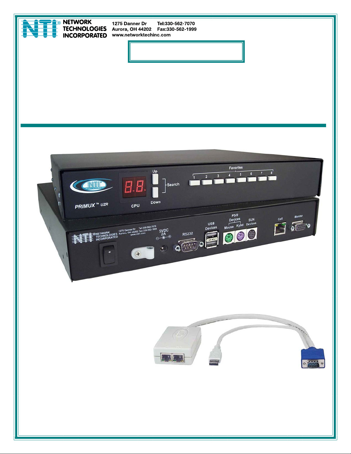
PRIMUX®Series
PRIMUX
CAT5 KVM System
Installation and Operation Manual
PRIMUX-UZR User Station
Host Adapter- (sold separatel
MAN024_v2.6 Rev 5/21/13
Page 2
TRADEMARK
PRIMUX is a registered trademark of Network Technologies Inc in the U.S. and other countries.
COPYRIGHT
Copyright © 2004, 2013 by Network Technologies Inc. All rights reserved. No part of this publication may be reproduced, stored
in a retrieval system, or transmitted, in any form or by any means, electronic, mechanical, photocopying, recording, or otherwise,
without the prior written consent of Network Technologies Inc, 1275 Danner Drive, Aurora, Ohio 44202.
CHANGES
The material in this guide is for information only and is subject to change without notice. Network Technologies Inc reserves the
right to make changes in the product design without reservation and without notification to its users.
FIRMWARE VERSION
PRIMUX Firmware Version 2.6
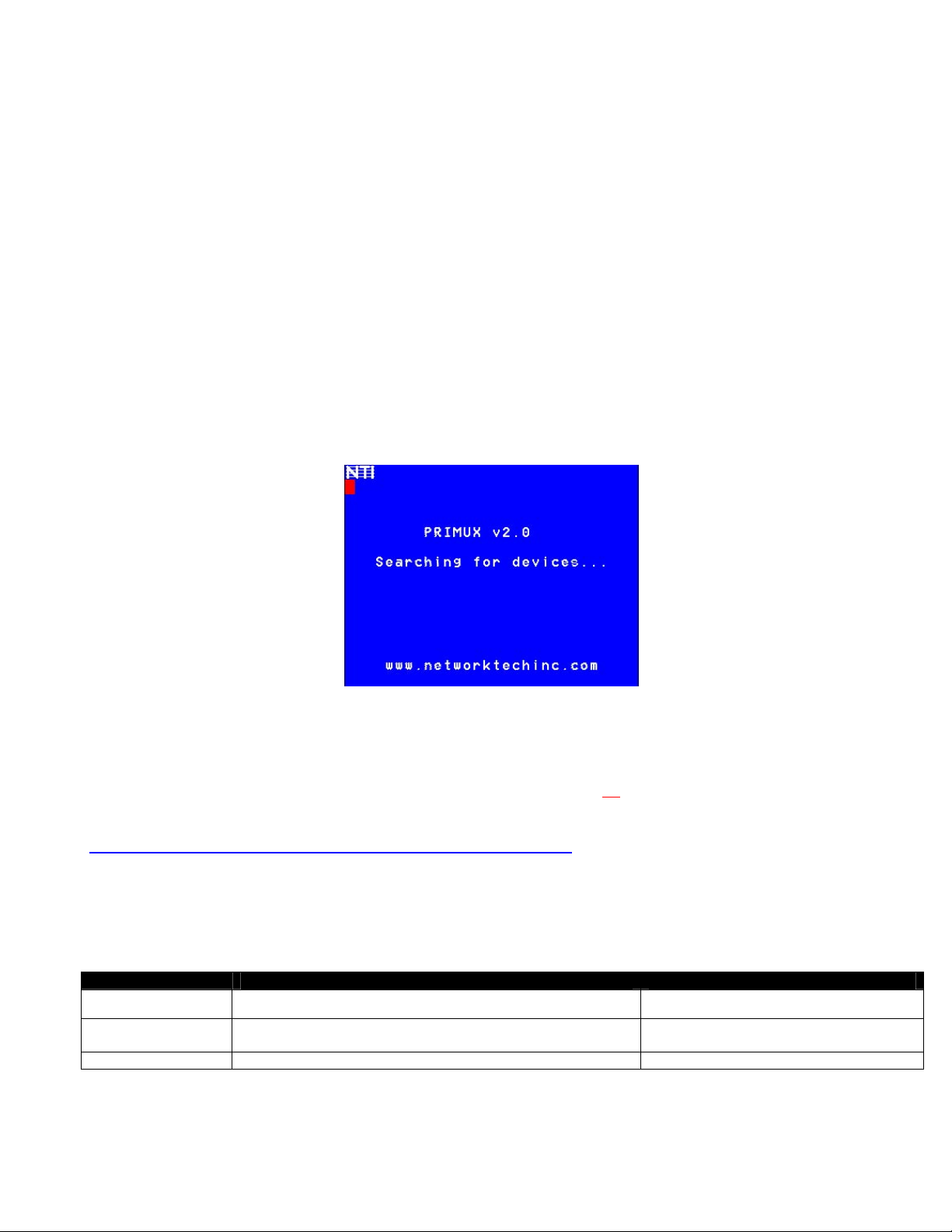
Please Note: This manual applies to PRIMUX with firmware version 2.0 and later. This version number can
be found in the splash screen viewed when the PRIMUX is first powered ON (example shown below). If no
version is shown, it is an earlier model. PRIMUX with earlier firmware versions are covered in manuals for
the PRIMUX dated prior to January 1, 2009. An earlier manual can be found at www.networktechinc.com.
Please Note: A PRIMUX-UZR User Station with firmware version 2.0 and later will not recognize or work
with a Host Adapter programmed with firmware version 1.6 and earlier. If you have Host Adapters with
firmware version 1.6 and earlier, they must first be updated to firmware version 2.0 using a PRIMUX-UZR
User Station programmed with firmware version 1.9. After updating all
User Station can then be updated to firmware version 2.0 to work with the newly updated Host Adap ters.
Firmware version 1.9 (with version 1.6 Host Adapter firmware) and firmware version 2.0 can be found at
http://www.networktechinc.com/download/d-kvmswitch-cat5.html
. Instruction for changing the firmware in
the User Station and Host Adapters is included in the .zip file with the firmware.
Typographic Conventions
The table below offers examples of text format and its meaning when used in place of the standard font (Helvetica) used
throughout this manual.
Typeface
AAaaBBaaCCcc123 On-screen computer output
AAaaBBaaCCcc123
---
See also “Standards of Operation” on page 16 for instruction on the use of the keyboard and mouse within OSD menus.
Meaning Example
What you type, contrasted with on-screen
computer output; keyboard keys to press
Press the “K” key on the keyboard
Host Adapters, the PRIMUX-UZR
C:>
C:> L
(Press the L key)
<K>
i
Page 3

TABLE OF CONTENTS
Introduction....................................................................................................................................................................1
Materials ......................................................................................................................................................................2
Features and Functions................................................................................................................................................3
Preparation for Installation...........................................................................................................................................4
Installation......................................................................................................................................................................5
The Host Adapter.........................................................................................................................................................5
Installation of a PS/2 CPU........................................................................................................................................5
Installation of a USB CPU.........................................................................................................................................6
Installation of a Legacy SUN CPU............................................................................................................................6
Installation of a Serial-Controlled Server or Device..................................................................................................7
Connecting the CAT5 cable to the Host Adapter......................................................................................................8
Daisy-Chained Host Adapters.....................................................................................................................................9
Adding a Host Adapter to the Daisy-Chain...............................................................................................................9
The User Station........................................................................................................................................................10
Installation with PS/2 devices.................................................................................................................................10
Installation with USB devices..................................................................................................................................10
Connecting the CAT5 cable to the User Station.....................................................................................................11
Power Up for the first time......................................................................................................................................12
Using the PRIMUX.......................................................................................................................................................13
Hot Plugging..............................................................................................................................................................13
Initial Startup..............................................................................................................................................................13
User Rights vs. Administrator Rights......................................................................................................................13
Setup Host Adapter(s)............................................................................................................................................14
Quick Connect to a CPU.........................................................................................................................................14
Change or Disable “root” Auto-login.......................................................................................................................14
Administrator Login and Password.........................................................................................................................14
Change the Default Administrator Password.............................................................................................................15
Guidelines for Navigating OSD Menus......................................................................................................................16
Keypad Control..........................................................................................................................................................17
Using the Search buttons .......................................................................................................................................17
Security......................................................................................................................................................................18
Auto-login................................................................................................................................................................18
Administrator Login.................................................................................................................................................18
User Login...............................................................................................................................................................18
User OSD Menus.......................................................................................................................................................19
Command Mode .....................................................................................................................................................19
Scan Mode..............................................................................................................................................................20
Normal Mode ..........................................................................................................................................................20
Settings Menu.........................................................................................................................................................21
OSD Settings Menu................................................................................................................................................22
Change Scan Dwell Time.......................................................................................................................................22
Select Hosts to Scan ..............................................................................................................................................23
ii
Page 4

Favorite Hosts.........................................................................................................................................................24
Video Quality Adjustment .......................................................................................................................................25
Test Patterns for Color Skew Adjustment...............................................................................................................25
Administrator Controls...............................................................................................................................................26
Administration Menu...............................................................................................................................................26
System Configuration Menu ...................................................................................................................................27
Configure Host Adapters ........................................................................................................................................29
Edit Host Adapter....................................................................................................................................................29
Configure Users......................................................................................................................................................32
Edit Users ...............................................................................................................................................................32
Add New User.........................................................................................................................................................33
Host Access Controls .............................................................................................................................................33
User Station Configuration......................................................................................................................................34
Select Auto-login User............................................................................................................................................35
Firmware Configuration Menu ................................................................................................................................36
Select Keyboard Language ....................................................................................................................................39
Network Configuration............................................................................................................................................40
HA-RS Configuration.................................................................................................................................................41
Help Menu...............................................................................................................................................................42
Setup Screen..........................................................................................................................................................42
Programmable Keys ...............................................................................................................................................43
View the Buffer........................................................................................................................................................43
Stop and Resume Output.......................................................................................................................................43
Keyboard Mapping......................................................................................................................................................44
Key Equivalents.........................................................................................................................................................44
SUN’s 16 Extra Keys.................................................................................................................................................44
Technical Specifications ............................................................................................................................................46
Interconnection Cable wiring Method.......................................................................................................................47
Null Modem Cable Pinouts.........................................................................................................................................47
Menu Quick-Find Keystroke Table............................................................................................................................48
Index.............................................................................................................................................................................49
Warranty Information..................................................................................................................................................49
TABLE OF FIGURES
Figure 1- Typical Application..............................................................................................................................................................4
Figure 2- Connect an HA-PS2 Host Adapter to a PS/2 CPU.............................................................................................................5
Figure 3- Connect an HA-USB Host Adapter to a USB CPU.............................................................................................................6
Figure 4- Connect an HA-SUN Host Adapter to a Legacy SUN CPU................................................................................................6
Figure 5- Connect an HA-RS Host Adapter to a server .....................................................................................................................7
Figure 6- Connect an HA-RS Host Adapter to a DCE type device.....................................................................................................7
Figure 7- HA-RS mounting base........................................................................................................................................................8
Figure 8- Connect CAT5 cable to Host Adapter.................................................................................................................................8
Figure 9- Daisy-chained Host Adapters.............................................................................................................................................9
Figure 10- Connect the Extended PS/2 components to the User Station ........................................................................................10
Figure 11- Connect extended USB components to the User Station...............................................................................................11
iii
Page 5

Figure 12- Connect CAT5 cable to User Station..............................................................................................................................11
Figure 13- Connect the AC adapter to the User Station...................................................................................................................12
Figure 14- OSD Menu Navigation....................................................................................................................................................16
Figure 15- PRIMUX-UZR front panel...............................................................................................................................................17
Figure 16- Login splash screen........................................................................................................................................................18
Figure 17- Command Mode main menu ..........................................................................................................................................19
Figure 18- Settings menu.................................................................................................................................................................21
Figure 19- OSD Settings Menu........................................................................................................................................................22
Figure 20- Scan Dwell Time field.....................................................................................................................................................22
Figure 21- Host Adapters to Scan list ..............................................................................................................................................23
Figure 22- Favorite Hosts list...........................................................................................................................................................24
Figure 23- Video Adjustment Screen...............................................................................................................................................25
Figure 24- Administration Menu.......................................................................................................................................................26
Figure 25- System Configuration menu ...........................................................................................................................................27
Figure 26- Configure DDC...............................................................................................................................................................28
Figure 27- Host Adapter List............................................................................................................................................................29
Figure 28- Edit Host Adapters menu................................................................................................................................................29
Figure 29- User Access Controls list................................................................................................................................................30
Figure 30- Share Mode Option (Matrix Mode only)..........................................................................................................................31
Figure 31- Configure Users menu....................................................................................................................................................32
Figure 32- Edit Users menu.............................................................................................................................................................32
Figure 33- Host Access Controls list................................................................................................................................................34
Figure 34- User Station Configuration screen..................................................................................................................................34
Figure 35- Select user for Auto-logIn...............................................................................................................................................35
Figure 36- Firmware Configuration Menu ........................................................................................................................................36
Figure 37- Update Host Adapters....................................................................................................................................................38
Figure 38- Select Keyboard Language menu ..................................................................................................................................39
Figure 39- Network Configuration page...........................................................................................................................................40
Figure 40- HA-RS User Interface.....................................................................................................................................................41
Figure 41- HA-RS Help Screen........................................................................................................................................................42
Figure 42- HA-RS Setup Screen......................................................................................................................................................42
Figure 43- HA-RS Programmable Keys Screen...............................................................................................................................43
Figure 44- Keyboard layouts............................................................................................................................................................45
Figure 45- View looking into RJ45 female........................................................................................................................................47
iv
Page 6

INTRODUCTION
The PRIMUX CAT5 KVM System (PRIMUX) allows the relocation of a VGA monitor, PS/2 or USB keyboard, and mouse from up
to 64 PS/2, legacy SUN, or USB CPUs by as much as 1000 feet. The PRIMUX is comprised of one PRIMUX-UZR User Station
for remote user control and at least one Host Adapter (HA-PS2, HA-USB, HA-SUN or HA-RS) connected to a local CPU. The
PRIMUX-UZR User Station supports PS/2 or USB user keyboard and mouse (devices). This manual describes the installation
and use of both components.
The PRIMUX Host Adapter and User Station are interconnected with either CAT5, CAT5e, CAT6 Unshielded Twisted Pair (UTP)
or CAT5, CAT5e Shielded Twisted Pair (STP) cable.
The PRIMUX User Station may be used to control a PRIMUX Matrix Switch. When connected to one of up to 8 user ports, the
PRIMUX User Station can be used to share access to up to 64 Host Adapters with the other User Stations connected to the
PRIMUX Matrix Switch. Features unique to Matrix Switch operation are highlighted throughout this manual where applicable.
The PRIMUX Series CAT5 KVM System is easy to install and has been thoroughly tested to insure reliable performance. Through
the use of CAT5, CAT5e, or CAT6 cable it is possible to economically increase the flexibility of a computer system. Here are
some of the features and ways this can benefit any workplace:
• Allows the placement of a monitor, keyboard, and mouse in a location where only these parts are needed without having
the CPU there too, taking up valuable space
• Rugged metal enclosure allows user to set the monitor directly on top
• Allows any PS/2, USB or legacy SUN CPU to be accessed by a remote user (up to 1000 feet away)
• Additional RJ45 port on the Host Adapter allows the daisy-chaining of up to 64 Host Adapters providin g user access to
up to 64 CPUs
• Control up to 64 CPUs from one keyboard, mouse, and monitor without "spaghetti" wiring
• Compatible with XGA, VGA, and SVGA systems
• Provides crisp and clear resolution up to 1024x768 /60Hz @ 1000 feet (usin g CAT 5 U TP cable- see pg 46 for details)
• Video quality adjustment is automatic providing optimum image q ua lity
• On Screen Display (OSD) menus enable easy configuration of the system (page 16)
• Allows for future expansion- buy what is needed now, add more later as desired
Supported Operating Systems
The PRIMUX is compatible with:
• Win9x • WinMe
• Windows 7
• WinNT • WinXP • MAC OS9.x , OSX
• Win2K
• WinVista
• Linux • Solaris
• Windo ws Serv er 2000,2003,2008
• FREE BSD
1
Page 7

D
Materials
Materials Supplied with this kit:
NTI PRIMUX-UZR User Station
AC Adapter Line cord, country specific
PRIMUX CD w/ Owner's Manual and
Quick Start Guide (pdf files)
Materials Not Supplied, but REQUIRED:
• NTI HA-PS2 PS/2 Host Adapter / HA-USB USB Host Adapter / HA-SUN Legacy SUN Host Adapter / HA-RS Serial Host
Adapter (see pg. 5)
• CAT5/5e/6 unshiel de d twisted-pair cable(s) terminated with RJ45 connectors wired straight thru- pin 1 to pin 1, etc. (see pg.
47 for proper EIA/TIA 568B wiring method)
• NTI-RJ45MF-RS232- CO crossover adapter will be needed if an HA-RS Host Adapter is being used and connected to a DCE
type device (see page 7)
Cables can be purchased from Network Technologies Inc by calling 800-RGB-TECH (800-742-8324) or (330)-562-7070 or
by visiting our website at www.networktechinc.com
Please Note: A PRIMUX-UZR User Station with firmware version 2.0 and later will not recognize or work with a Host
Adapter programmed with firmware version 1.6 and earlier. If you have Host Adapters with firmware version 1.6 and
earlier, they must first be updated to firmware version 2.0 using a PRIMUX-UZR User Station programmed with firmware
version 1.9. After updating all
2.0 to work with the newly updated Host Adapters. Firmware version 1.9 (with version 1.6 Host Adapter firmware) and
firmware version 2.0 can be found at http://www.networktechinc.com/download/d-kvmswitch-cat5.html
changing the firmware in the User Station and Host Adapters is included in the .zip file with the firmware.
Note: The HA-RS Host Adapter will only work with User Stations programmed with firmware version 2.0 and later.
Host Adapters, the PRIMUX-UZR User Station can then be updated to firmware version
120VAC or 240VAC @ 50 or 60Hz -5VDC/2A AC Adapter
INT-6-FF Null Modem Cable
PRIMUX Quick Start Guide (printed)
.
Terminating Plug
. Instruction for
2
Page 8
NTI
Network Technolo gies Inc
PRIMUX
1
2
3
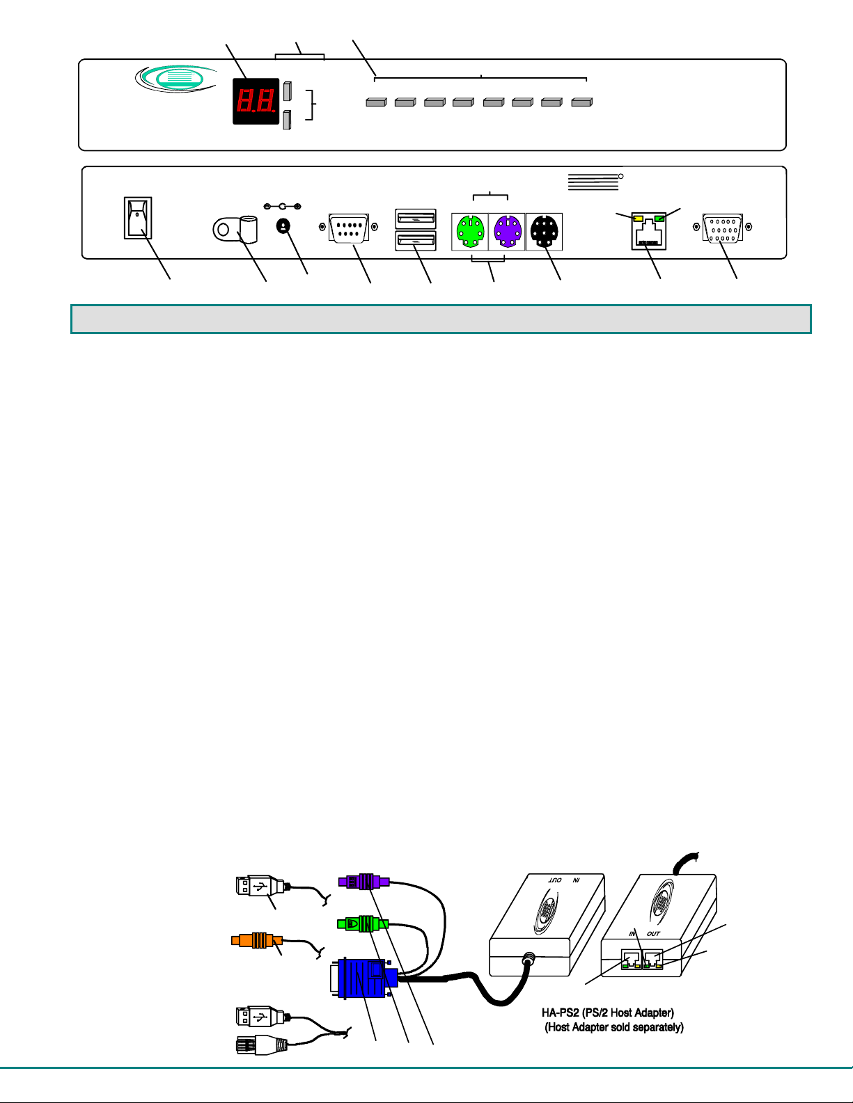
Front View of PRIMUX-UZR (User Station)
R
TM
UZR
CPU
Up
Search
Down
Favorites
7654321
8
Rear View of PRIMUX-UZR (User Station)
5VDC
2A
RS232
USB
Devices
Mouse
PS/2
Devices
Kybd
SUN
Devices
NTI
11a
R
NETWORK
TECHNOLOGIES
INCORPORATED
Cat5
1275 Danner Dr
Aurora, OH 44202
11b
Tel:330-562-7070
Fax:330-562-1 999
www.nti1.com
Monitor
+
4
6
5
7
8
9
10
11
12
FEATURES AND FUNCTIONS
1. LED Display- for visual indication of which Host Adapter the user is connected to
2. Search Buttons- to enable manual search for desired Host Adapter connection
3. Favorite Buttons- programmable buttons to quick selection of specific Host Adapters
4. Power Switch- to turn the User Station ON and OFF
5. Cable Clamp- to secure the cable from the AC adapter
6. 5VDC 2A- 3.5mm power jack- for connection of AC adapter
7. RS232- DB9 male- serial communication port for updating firmware
8. USB Devices- USB Type A female- for connection of USB user devices (keyboard and mouse)
9. PS/2 Devices- green and purple 6mD females- for connection of PS/2 type mouse (green) and keyboard (purple)
10. SUN Devices- black 8mD female- for connection of SUN mouse and keyboard (not supported at this time)
11. Cat5 - RJ45 female- for connection of CAT5 cable between Host Adapter and User Station
11a. Yellow LED- power indicator- illuminates when power has been supplied to the unit
11b. Green LED- traffic indicator- illuminates when there is communication between the User Station and Host
12. Monitor- for connecting the video monitor
13. Video Connector- blue 15HD male- for connecting to the video port on the CPU
14. Mouse Connector- green male 6 miniDIN (HA-PS2 only)- for connecting to the mouse port on a PS2 CPU
15. Keyboard Connector- purple male 6 miniDIN (HA-PS2 only)- for connecting to the keyboard port on a PS2 CPU
15a. Device Connector- male USB Type A (HA-USB only)- for connecting to a device port on a USB CPU
15b. Device Connector- orange male 8 miniDIN (HA-SUN only) - for connecting to the device port on a SUN CPU
15c. Power and Serial Connectors-USB Type A and RJ45 male(HA-RS only)- for connecting to the serial port on a t ermina l
and powering the Host Adapter
16. Cat5- RJ45 female- for connection of CAT5 cable between daisy-chained Host Adapters
Adapters.
15a
15b
15c
13 14 15
(Front View)
16
11b
(Rear View)
11
11a
3
Page 9
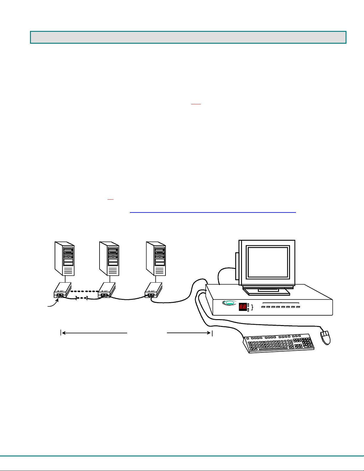
PREPARATION FOR INSTALLATION
• Choose a location for the User Station such that cables from the keyboard, mouse, and monitor will reach it.
• The CAT5 cables must be run between the locations where the Host Adapter will be connected and User Station is
NOTE: The installer must ensure that all CAT5 cable between the Host Adapter and User Station and between each Host
Adapter (if more than one) is of the straight-through type and not
• A 120V or 240V electrica l supply (depending on the AC adapter being used) must be provided close enough to the position of
• All cables shou ld be installed such that they do not cause stress on their connections to the equipment. Extended lengths of
• Properly shut d own a nd disconnect the power from the CPU and devices to be extended. If other equipment is involved
Please Note: A PRIMUX-UZR User Station with firmware version 2.0 and later will not recognize or work with a Host
Adapter programmed with firmware version 1.6 and earlier. If you have Host Adapters with firmware version 1.6 and
earlier, they must first be updated to firmware version 2.0 using a PRIMUX-UZR User Station programmed with firmware
version 1.9. After updating all
2.0 to work with the newly updated Host Adapters. Firmware version 1.9 (with version 1.6 Host Adapter firmware) and
firmware version 2.0 can be found at http://www.networktechinc.com/download/d-kvmswitch-cat5.html. Instruction for
changing the firmware in the User Station and Host Adapters is included in the .zip file with the firmware.
PS/2,
USB,
or SUN
Host
Adapter
Terminating
Plug in "IN"
Figure 1- Typical Application
positioned. Be careful to route the cables away from any sources of magnetic fields or electrical interference that might
reduce the quality of the signal (i.e. AC motors, welding equipment, etc.) .
crossed.
the User Station to plug the AC adapter into.
cable hanging from a connection may interfere with the quality of that connection. Secure cables as needed to minimize this.
whose connections are being interrupted, be sure to refer to the instruction manuals for that equipment for proper
disconnection and re-connection procedures before procee ding.
Host Adapters, the PRIMUX-UZR User Station can then be updated to firmware version
PS/2,
USB,
or SUN
CPU 1
VGA
Multi-Scan
CPU 64
CPU 2
PS/2,
USB,
or SUN
Monitor
Host
Adapter
CAT5 Cable
Host
Adapter
CAT5 Cable
CAT5 Cable
PRIMUX
NTI
Network Technologies Inc
R
Up
TM
UZR
Search
CPU
Down
Front View of PRIMUX-UZR
Favorites
87654321
UP TO 1000'
SUN USB Keyboard/Mouse
4
Page 10
INSTALLATION
The Host Adapter
The PRIMUX HA Host Adapter is designed to support PS/2, SUN and USB CPUs, as well as serial-controlled servers and
devices (see chart below). Host Adapters may be connected to or removed from a CPU without powering down the CPU, provided
the CPU and operating system supports device hot plugging. (Operating systems known to support hot-plugging include Windows
2000 SP3 and higher, Windows XP, Windows Vista, and Linux. )
CPU TYPE HOST ADAPTER MODEL
PS/2 HA-PS2
SUN HA-SUN
USB HA-USB
SERIAL HA-RS
Note: The HA-RS Host Adapter will only work with User Stations programmed with firmware version 2.0 and later.
Note: All Host Adapters must be programmed with firmware version 2.0 in order to work with a User Station programmed
with firmware version 2.0 and later. See “Please Note...” on page i.
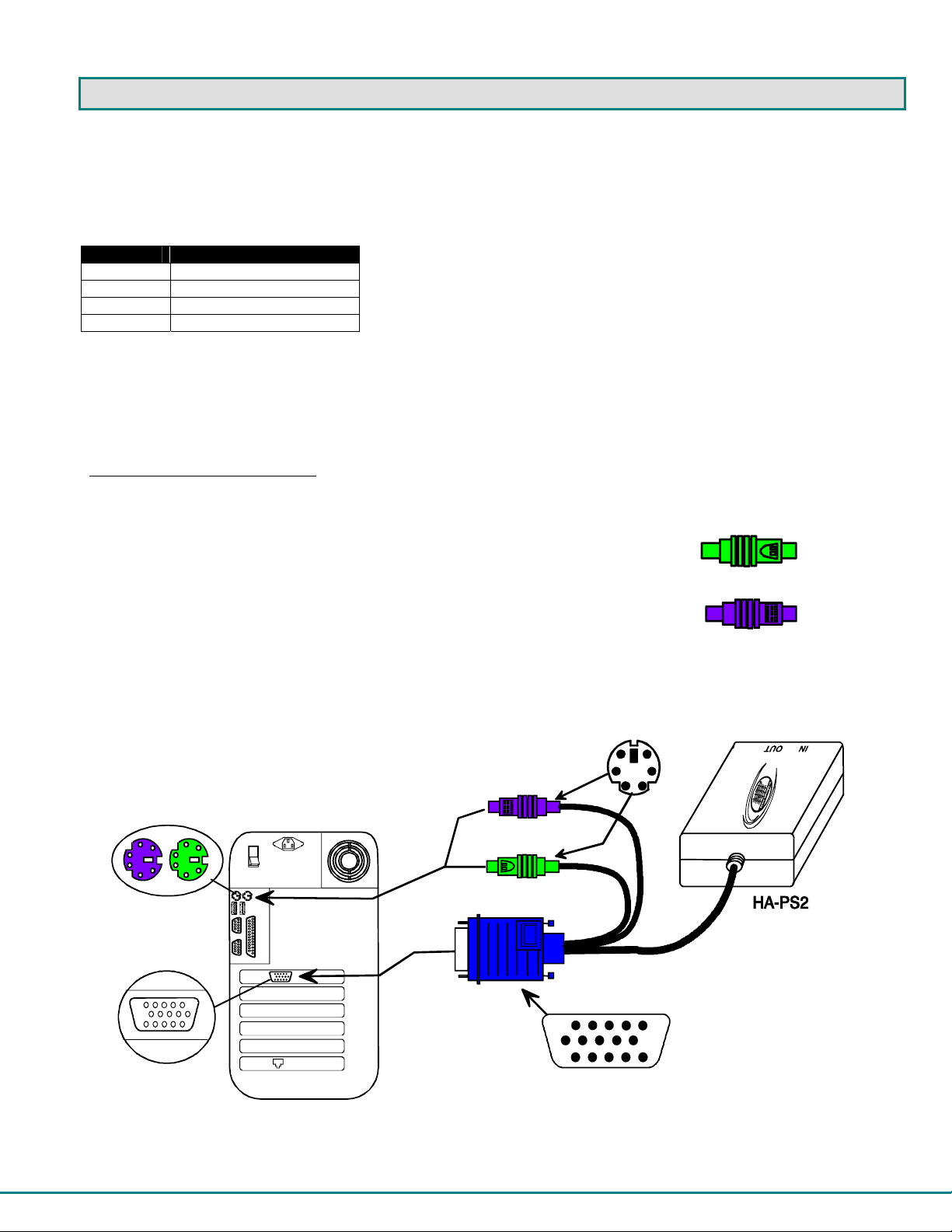
Installation of a PS/2 CPU
Plug the cables of the HA-PS2 Host Adapter into the back of the CPU after disconnecting the power cord from the CPU.
(See Figure 2.)
a) Connect the green 6 pin miniDIN cable end with the mouse symbol
on it to the mouse port on the back of the CPU.
b) Connect the purple 6 pin miniDIN cable end with the keyboard symbol
on it to the keyboard port on the back of the CPU.
c) Connect the blue 15HD cable end to the VGA port on the back of the CPU.
6 pin miniDIN
female connectors
15HD female
video connector
Figure 2- Connect an HA-PS2 Host Adapter to a PS/2 CPU
Rear View of PS/2 CPU
purple-keyboard
green-mouse
6 miniDIN
male connectors
15HD male
video connector
PS/2 Mouse
PS/2 Keyboard
(Front View)
5
Page 11
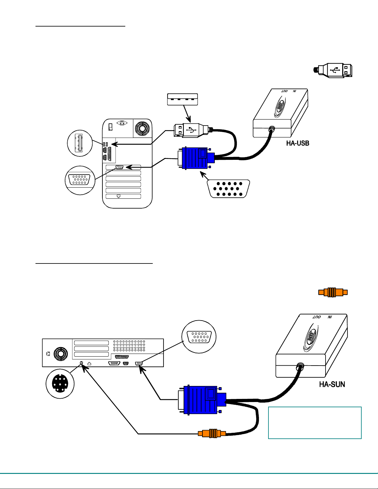
Installation of a USB CPU
Plug the cables of the HA-USB Host Adapter into the back of the CPU after disconnecting the power cord from the CPU.
(See Figure 3.)
a) Connect the cable with the USB Type A male cable end on it to a USB Type A female port on the back of the
CPU.
b) Connect the blue 15HD cable end to the video connector on the back of the CPU.
Figure 3- Connect an HA-USB Host Adapter to a USB CPU
USB Type A
device port
15HD female
video connector
Rear View of USB CPU
USB Type A male
15HD male
video connector
(Front View)
USB Devices
Installation of a Legacy SUN CPU
Plug the cables of the HA-SUN Host Adapter into the back of the CPU after disconnecting the power cord from the CPU.
(See Figure 4.)
a) Connect the orange 8 pin miniDIN cable end on it to the devices port on the back of the CPU.
b) Connect the blue 15HD cable end to the VGA port on the back of the CPU.
8 pin miniDIN
female connector
Figure 4- Connect an HA-SUN Host Adapter to a Legacy SUN CPU
Rear View of SUN CPU
15HD female
video connector
orange-devices
FYI: The HA-SUN Host Adapter
does not provide keyboard
power-ON support for legacy
SUN CPUs.
SUN Devices
(Front View)
6
Page 12
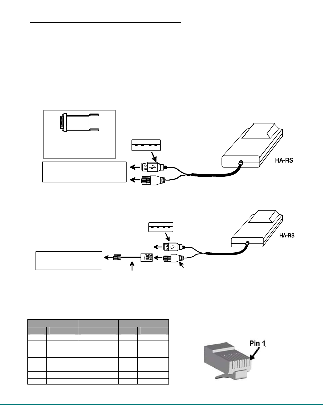
Installation of a Serial-Controlled Server or Device
Plug the cables of the HA-RS Host Adapter into the serial port on a server or other serially-controlled data terminal equipment
(DTE) device. If the device is a data communication equipment (DCE) type device, an NTI RJ45MF-RS232-CO crossover cable
or adapter (see bottom of this page) will be required (sold separately).
a) Connect the RJ45 cable end to the serial control port on the serial device. A DB9 to RJ45 console adapter
(supplied with HA-RS) may be required to make this connection.
b) Connect the USB Type A cable to any available USB Type A female port. If the device being controlled does not
have a USB port, connect it to any USB Type A port on a device nearby. Any USB Type A port will do, as the
HA-RS is only using the power supplied by two of the four terminals in the connector.
Note: The HA-RS Host Adapter will only work with User Stations programmed with firmware version 2.0 and later.
Note: All Host Adapters must be programmed with firmware version 2.0 in order to work with a User Station programmed
with firmware version 2.0 and later. See “Please Note...” on page i.
DB9F-RJ45F
Console Adapter
(Supplied with HA-RS)
SERIAL -CONTROLLE D SER VER
(DTE)
Figure 5- Connect an HA-RS Host Adapter to a server
Figure 6- Connect an HA-RS Host Adapter to a DCE type device
Pinout for RJ45 Female to RJ45 Male crossover Adapter
CONNECT TO ANY AVAILABLE USB PORT
(HA-RS USES POWER TERMINALS ONY)
NTI SERIMUX/ IPDU-S2/ (ETC.)
(DCE DEVICE)
RJ45MF-RS232-CO
SERIAL CROSSOVER ADAPTER
(sold separately)
USB Type A male
(Front View)
USB Type A male
(Front View)
RJ45 Male
RJ45-F RJ45-M
Pin Signal Pin Signal
1 CTS Connected to 8 RTS
2 DSR Connected to 7 DTR
3 RxD Connected to 6 TxD
4 GND Connected to 4 GND
5 DCD Connected to 1 CTS
6 TxD Connected to 3 RxD
7 DTR Connected to N/c
8 RTS Connected to 2 DSR
Note: The serial port on the device must be configured for a maximum baud rate of 115200 bps.
7
Page 13
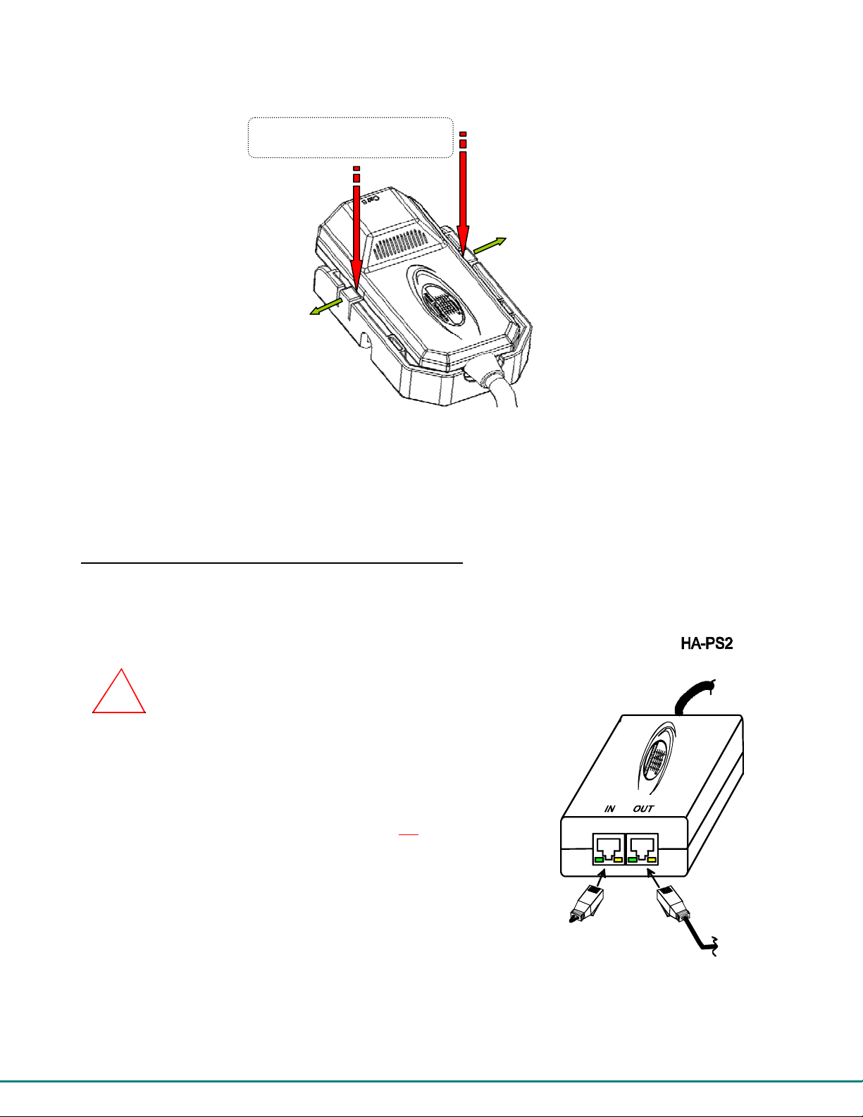
p
The HA-RS Host Adapter includes with a base for mounting to any desired surface. To Host Adapter snaps-in securely, and is
quickly released from the base by applying pressure to the two release tabs, as shown in the image belo w.
To release adapter apply
ressure as shown
Figure 7- HA-RS mounting base
For instruction on configuration of the HA-RS to make connection to the serial device, see page 41.
Connecting the CAT5 cable to the Host Adapter
Connect CAT5 cable to the “OUT” port on the Host Adapter. (See Figure 8.) When properly inserted the cable end shou ld snap
into place. Also be sure to insert the Terminating Plug (HA-PLGTRM) into the "IN" port on the Host Adapter if this is the only Host
Adapter in the system. Otherwise, see "Daisy-Chained Host Adapters" on page 9 to add more Host Adapters to the system.
!
WARNING: Never connect the PRIMUX Host Adapter to an Ethernet card,
Ethernet router, hub or switch or other Ethernet RJ45 connector of an Ethernet
device. Damage to devices connected to the Ethernet may result.
NOTE: The installer must ensure that all CAT5 cable between the Host
Adapter
and User Station is of the straight-through type and not
Figure 8- Connect CAT5 cable to Host Adapter
crossed.
Terminating
Plug (Supplied)
(Rear View)
Cable to CPU
CAT5 Cable
to User Station
8
Page 14
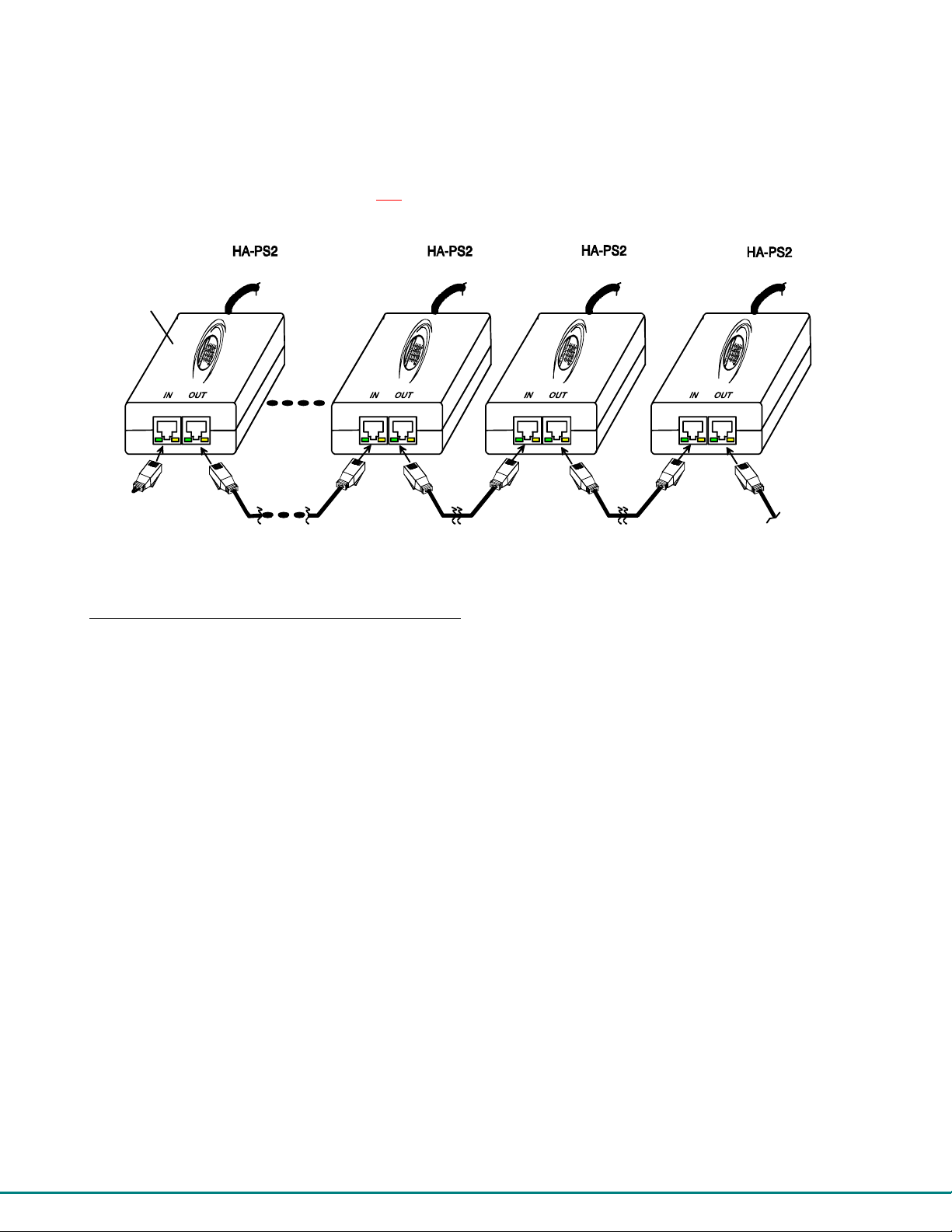
Daisy-Chained Host Adapters
Up to 64 Host Adapters can be connected in a daisy-chain to create a series of CPUs that are controlled by a single user from a
User Station. The first Host Adapter is connected to the User Station via the "OUT" port. The additional Host Adapters in the
chain will have CAT5 cable going from their "OUT" port to another Host Adapter's "IN" port to enable communications between the
user and each CPU in the system, as shown in Figure 9. A Terminating Plug must be installed in the "IN" port of the last Host
Adapter in the daisy-chain.
NOTE: The installer must ensure that all CAT5 cable terminations between each Host Adapter are of the straight-through
type (pin 1 to pin 1, pin 2 to pin 2, etc.) and not
NOTE: The total length of the CAT5 cable from the User Station to the last Host Adapter in the daisy-chain must not
exceed 1000'.
Last Host
Adapter in
the daisy-chain
(Rear View)
Cable to CPU 64
Terminating
Plug (Supplied)
CAT5 Cable
CAT5 Cable
Figure 9- Daisy-chained Host Adapters
crossover.
(Rear View)
CAT5 Cable
Cable to CPU 3
(Rear View)
CAT5 Cable
Cable to CPU 2
(Rear View)
CAT5 Cable
to User Station
Cable to CPU 1
Adding a Host Adapter to the Daisy-Chain
When adding a Host Adapter to a daisy-chain, whether at the end, or inside the chain (between two other Host Adapters
connected together), the administrator must follow some simple steps:
1. Make sure the Host Adapter being connected to a CPU is the proper type for the CPU. Host Adapters are either HA-PS2
(for PS/2 CPUS), HA-USB (for USB CPUs), HA-SUN (for legacy SUN CPUs) or HA-RS (for serial-controlled devices).
2. Determine what name the Host Adapter will be identified as in the Host Adapter list. The PRIMUX will automatically name it
for the PN# (part number) found on the case of the Host Adapter. (This name can be changed later- page 29.)
3. Follow the installation instruction on page 5 for Host Adapters and above for Daisy-Chained Host Adapters.
FYI: A Host Adapter can be added to the last Host Adapter in the chain, or between two existing Host Adapters.
4. Once the installation procedure is complete the connected CPU must be powered ON.
Note: The connected CPU must be powered ON at least once in order for the Host Adapter to be identified and registered
by the User Station as indicated in the Command Mode OSD list (for more on “Command Mode” see page 19).
5. This Host Adapter will be auto-discovered by the PRIMUX. If the Host Adapter is new (unused), it will identify itself as
"PN:xxxxxxxx)" (where xxxxxxxx is the part number of the Host Adapter).
Note: If the Host Adapter has been previously connected and the name is still present in the Host Adapter list, it will still
have the name and settings it was originally configured with. To delete those settings in the PRIMUX, delete the Host
Adapter from the Edit Host Adapter menu (page 29).
Note: A PRIMUX in Matrix Mode (page 34) will not auto-discover a Host Adapter. To force a Host Adapter to be
discovered after connecting it to a PRIMUX Matrix Switch, press <F5> while in Command Mode.
6. The administrator should assign a unique name to the Host Adapter (see page 29)
7. Only users with administrator rights will have access to the new Host Adapter unless the administrator assigns additional
users access (see page 32).
Once access controls have been set, the administrator should verify the security access to the new Host Adapter.
9
Page 15
The User Station
The PRIMUX-UZR User Station can be used with either PS/2 devices or USB devices.
NOTE: If the user keyboard connected is PS/2 (6mD connector), then the mouse must also be PS/2. If the user keyboard
is USB (USB Type A connector), then the mouse must also be USB.
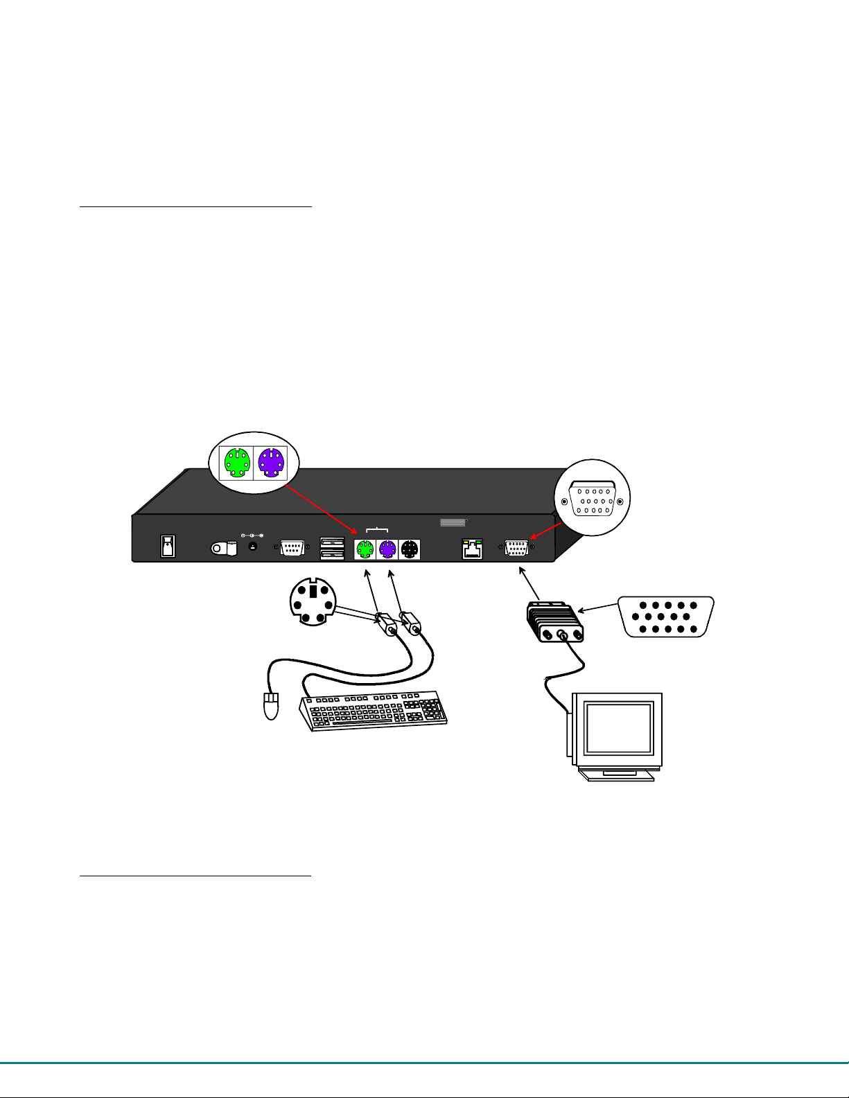
Installation with PS/2 devices
1. Position the User Station such that the CAT5 cable, the monitor cable, device cables, and the AC adapter power connector
can each reach the User Station without cable strain.
2. Connect the monitor cable to the female 15HD video connector on the User Station.
3. Connect the PS/2 device(s) to the User Station (see Figure 10).
a. Connect the keyboard to the purple female 6 pin miniDIN connector labeled “Kybd” on the User Station.
b. Connect the mouse to the green female 6 pin miniDIN connector labeled “Mouse” on the User Station.
5VDC
2A
+
male connectors
PS/2
Mouse
Figure 10- Connect the Extended PS/2 components to the User Station
6 pin miniDIN
female connectors
Rear View of
PRIMUX-UZR User Station
USB
Devices
RS232
Mouse
6 miniDIN
PS/2 Keyboard
PS/2
Devices
Kybd
SUN
Devices
NTI
R
NETWORK
TECHNOLOGIES
INCO RPO RAT ED
Cat5
1275 Danner Dr
Aurora, OH 44202
www.nti1.com
Monitor
Tel:330-562-7070
Fax:330-562-1999
15HD female
video connector
15HD male
video connector
VGA
Multi-Scan
Monitor
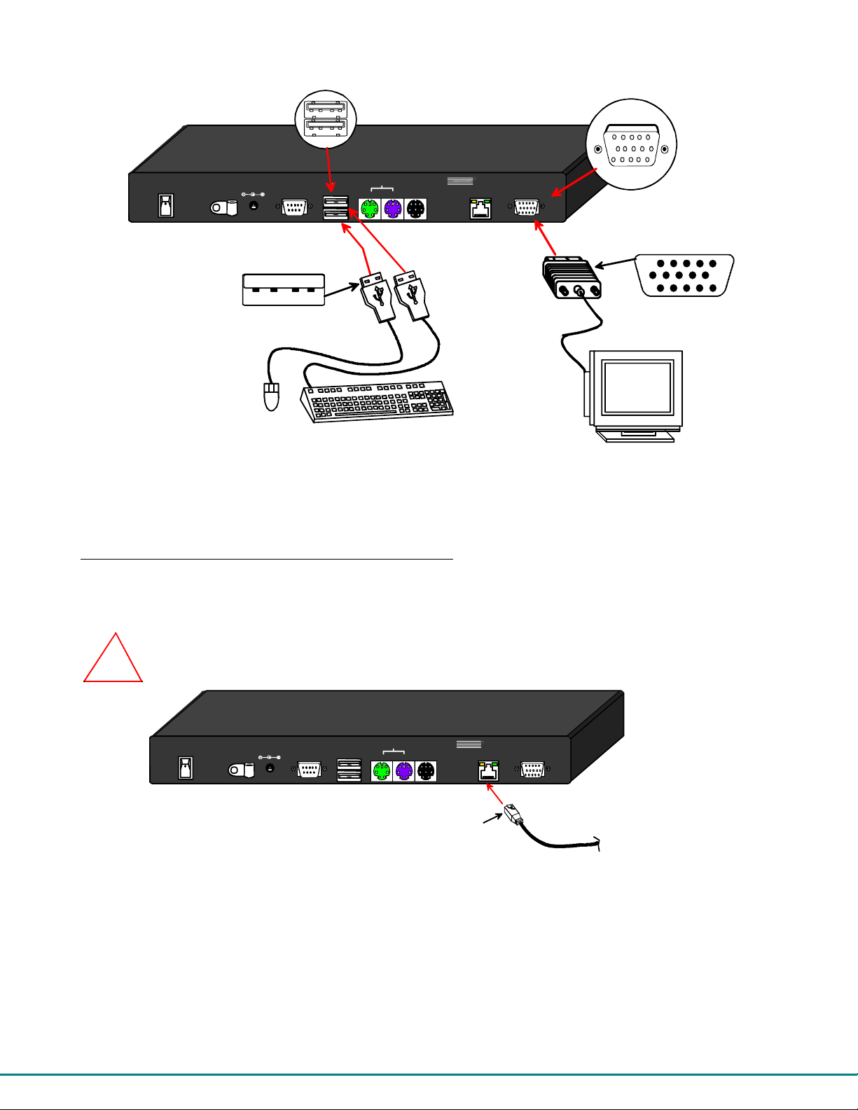
Installation with USB devices
1. Position the User Station such that the CAT5 cable, the monitor cable, device cables, and the AC adapter power connector
can each reach the User Station without cable strain.
2. Connect the monitor cable to the female 15HD video connector labeled “Monitor” on the User Station.
3. Connect the USB device(s) to the User Station (see Figure 11).
a. Connect the keyboard to a USB Type A female connector on the User Station.
b. Connect the mouse to the other USB Type A female connector on the User Station.
10
Page 16
USB Type A female
device ports
5VDC
2A
RS232
+
PRIMUX-UZR User Station
PS/2
Mouse
Devices
Kybd
SUN
Devices
USB
Devices
USB Type A male
USB
Mouse
USB Keyboard
Figure 11- Connect extended USB components to the User Station
15HD female
video connector
R
NTI
NETWORK
TECHNOLOG IES
INCORPORAT E D
Cat5
1275 Danner Dr
Aurora, OH 44202
www.nti1.com
Monitor
Tel:330-562-7070
Fax:330-562-1999
Multi-Scan
15HD male
video connector
VGA
Monitor
Connecting the CAT5 cable to the User Station
Make sure the CAT5 cable has been installed in accordance with the “Preparation for Installation” instructions on pag e 4.
Connect the CAT5 cable to the RJ45 connector labeled “Cat 5” on the User Station. (See Figure 12.) When properly in serted the
CAT5 cable end should snap into place.
WARNING: Never connect the PRIMUX-UZR User Station to an Ethernet card, Ethernet router, hub or switch
or other RJ45 connector of an Ethernet device. Damage to devices connected to the Ethernet may
!
result.
+
Figure 12- Connect CAT5 cable to User Station
NOTE: If an RJ45 wall outlet is being used, connect the other end of the extension cable to the RJ45 wall outlet.
Rear View of PRIMUX-UZR User Station
R
5VDC
2A
RS232
USB
Devices
Mouse
PS/2
Devices
Kybd
SUN
Devices
NTI
NETWORK
TECHNOLOGIES
INCORPORAT ED
Cat5
RJ45 male
CAT5 connector
1275 Danner Dr
Aurora, OH 44202
www.nti1.com
Monitor
Tel:330-562-7070
Fax:330-562-1999
CAT5 cable
to first Host Adapter
in the daisy- chain
11
Page 17
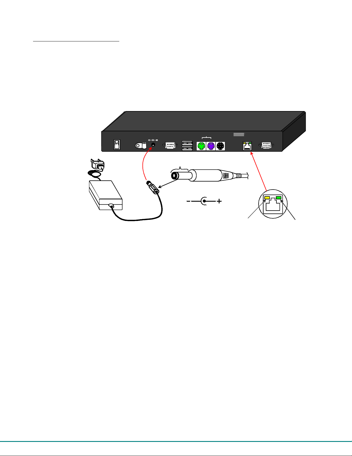
Power Up for the first time
Note: The user devices, monitor, and CAT5 cable should already be connected before powering up the User Station.
1. Connect the AC adapter power connector to the 5VDC port on the User Station (see Figure 13). Plug the AC adapter into a
power outlet and press the power switch to turn the User Station ON. The yellow LED on the RJ45 connector of the User
Station should illuminate, indicating that a proper power connection has been made to it.
2. Re-connect the power cord to the CPU.
FYI: The Host Adapter is powered by the CPU.
3. Power up the monitor.
5 VDC
AC
ADAPTER
Rear View of PRIMUX-UZR User Station
PS/2
5VDC
2A
+
RS232
Devices
Devices
USB
Mouse
Rear View of PRIMUX-UZR
SUN
Devices
Kybd
Barrel
Power Connector
5VDC @ 2.0A OU TPUT
(Outside
barrel)
(Inside
barrel)
2.1 mm x 5.5 mm Female
NTI
R
Cat5
Yellow-Power
LED
NETWORK
TECHNOLOGIES
INCOR POR A TED
Tel:330-562-7070
1275 Danner Dr
Fax:330-562-1999
Aurora, OH 44202
www.nti1.com
Monitor
Green-Communication
LED
Figure 13- Connect the AC adapter to the User Station
4. With the User Station and Host Adapter connected via CAT5 cable, refer to "Using the PRIMUX " on page 13.
FYI: The green LED on each RJ45 connector will illuminate anytime data traffic is passing between the Host Adapter and
User Station, indicating proper CAT5 cable connection and communication. (See Figure 13)
12
Page 18

USING THE PRIMUX
The PRIMUX CAT5 KVM System is designed to enable a user to control as many as 64 PS/2, USB and legacy SUN CPUs (any
mixture of each) from a single User Station as much as 1000 feet from the farthest CPU. Control is achieved through the use of
either the keypad on the front panel or On Screen Display (OSD) Menus. Access to one or more CPUs is determined by the
security configuration of the PRIMUX as set by the administrator. Once user access limitations are defined, the user can select
which CPU to connect to using either the OSD menu, the "Search" buttons on the front of the User Station, or quickly make a
selection after programming the "Favorite" buttons.
Hot Plugging
The PRIMUX-UZR is designed to emulate the presence of a mouse and keyboard whenever the PRIMUX-UZR is po wered ON.
As a result, the keyboard and mouse may be hot-plugged from the User Station at any time without causing a CPU error.
Note: Device types cannot be changed when hot-plugging. If the device type is changed (i.e. from PS/2 to USB), the
PRIMUX-UZR must be power cycled (turned OFF, then ON again) for the device to work properly.
Note: Both devices must be either PS/2 or USB. There cannot be one of each connected to the User Station.
The PRIMUX Host Adapter may also be hot-plugged to a CPU, provided the CPU and the operating system supports device hotplugging. (Operating systems known to support hot-plugging include Windows 2000 SP3 and higher, Windows XP, Windows
Vista, Linux, Windows Server 2000,2003 and 2008.)
Note: When hotplugging the mouse and keyboard cables into a PS/2 CPU that is known to support hotplugging, be sure
to connect the mouse cable first, then the keyboard cable. Failure to connect in this order may cau se the mouse to not
be recognized by the CPU.
CAT5 cables can be hot plugged. If the CAT5 cable is disconnected, the User Station will continue to monitor all Host Adapters in
the Host Adapter List.
FYI: Once a Host Adapter is selected by the User Station it will stay connected or attempt to connect forever if the
selected Host Adapter is powered OFF or the CAT5 cable is disconnected. To properly remove a Host Adapter, the user
must delete it from the Host Adapter List (page 29).
Hot plugging a Host Adapter to an NTI VOPEX splitter is not recommended.
Initial Startup
After installing the User Station and one or more Host Adapters as described on pages 4-8, when first app lying power the user
named “root” will be automatically logged-in and the Command Mode OSD menu will appear. By default, the root user has full
administrator rights and access to all Host Adapters and their connected CPUs.
User Rights vs. Administrator Rights
The Administrator has full control over the functions of the PRIMUX CAT5 KVM system, while the User has limited control.
Administrator Rights Include:
FYI: Users can be given full administrative access rights by the administrator (see page 32).
User Rights Include:
¾ Change the Administrator Password
¾ Assign, edit, and remove user names and passwords
¾ Define user access rights to CPUs
¾ Adding and configuring Host Adapters
¾ Configure operating paramete rs of the User Station
¾ Update DDC information between the monitor and CPUs
¾ The ability to connect the User Station’s keyboard, mouse, and monitor to any CPU
¾ The ability to enable/disable and configure Scan Mode
¾ The ability to assign a list of favorite CPUs
¾ The ability to fine tune the video quality
¾ The ability to connect the Users Station’s keyboard, mouse, and monitor to CPUs (only those CPUs that have been
granted access by the administrator).
¾ The ability to enable/disable and configure Scan Mode
¾ The ability to assign a list of favorite CPUs
¾ The ability to fine tune the video quality
13
Page 19

Setup Host Adapter(s)
No initial configuration of the Host Adapter is required for it to be identified by the User Station. Once discovered, it appears in
the list of CPUs in the Command Mode main menu. The name will appear as “PN:xxxxxxxx” where xxxxxxxx is the number found
on the Host Adapter case. The name can be edited later (see page 29).
Note: In order for the User Station to identify a Host Adapter and be included in the OSD list of connected CPUs (page
19) , the CPU must be powered-ON at least once. After the first powered-ON connection, the User Station will indicate
the status of the connected CPU, whether it is powered-ON or not..
Note: All Host Adapters must be programmed with firmware version 2.0 in order to work with a User Station programmed
with firmware version 2.0 and later. See “Please Note...” on page i.
Quick Connect to a CPU
For OSD menu Navigation guidlelines, see page 16.
From the Command Mode menu (page 19), to make connection to any Host Adapter in the daisy-chain,
press <Up arrow> or <Down arrow> to highlight and select the desired Host Adapter, press
<Enter> to connect to it.
-OR-
use the mouse to highlight the desired Host Adapter to connect to and click on it to connect.
Press <Esc> to exit Command Mode and use the connected CPU.
Press <Ctrl> + <`> to return to Command Mode if desired.
Change or Disable “root” Auto-login
For security purposes, it is recommended that the Auto-login feature either be disabled or the Auto-login user be changed to a
user with fewer rights than the administrator.
To disable
To change the Auto-login, from the main menu,
Press <L> - <Y> to logout and return to a login prompt.
To return to the Command Mode menu via Auto-login, press <F1>. You will be logged in as “user1” .
To login as the administrator, see below.
Note: If the PRIMUX is power cycled, the PRIMUX will now auto-login and open into the Command Mode menu with
user1 logged in.
the Auto-login, from the main menu, press <A> -<R>-<A>-<N>.
- press <A> -<U>-<A>-<Y>-<F10> to first establish “user1” with no Host Adapter access but no administrative
privileges
- press <A> -<R>-<A> and select “user1” for Autologon. (Selection can be made using left mouse click or spacebar)
- press <F10> to return to the main menu.
Administrator Login and Password
To login as the administrator
, from the login prompt, enter the administrator name and default password:
administrator name = <root>
administrator password = <nti>
Note: User names and passwords are case sensitive.
With a successful login, the administrator can setup additional users (see page 32).
FYI: The User Station can be configured to Autologon a specific user (page 35) with each Use r Statio n power-up or have
a Login splash screen appear for the user to login to the User Station.
NOTE: In PRIMUX units with firmware version 1.9 and earlier, the administrator name was “ADMINISTRATOR” and the
password was “NTI” (all upper case letters).
14
Page 20

Change the Default Administrator Password
Once the administrator is logged in, it is recommended (for greater security) that the the administrator change the default
administrator password.
To change the administrator password:
-
Press <A> (Administration Menu) - <U> (User Configuration)
- Select the user “root” to open the “Edit User” menu
-
Press <P> to open the “password” field.
- Type in a new password (case sensitive, 16 characters maximum, alphanumerc)
Press <Tab> to open the “confirm” field
-
- Re-type the new password to confirm
Press <Enter> to finish and save.
-
Note: If you press <Enter> again, you will have to retype the confirmation.
Press <Esc> to exit the menu, or <P> to change it again.
Note: In the event the password is forgotten, contact NTI for instruction on how to reset the password to the default
"nti".
Note: User names and passwords are case sensitive.
15
Page 21

Guidelines for Navigating OSD Menus
Throughout this manual, various rules apply for navigating the menus used to control and operate the PRIMUX.
• OSD menus can be nav igated using the mouse, the up and down arrows on the keyboard, and the <Page Up>, <Page
Down>, <Home>,<Tab> and <End> keys.
-
The up and down arrows increment/decrement one line item at a time
-
<Page Up> and <Page Down> increment/decrement by one page at a time
- <Home> will jump to the beginning of the list
<Tab> will jump between selectable fields (on supported screens)
-
<End> will jump to the end of the list.
-
• Alphabetic and numeric characters can be typed in the OSD menu fields, as well as these additional ch aracters:
! (exclamation point) , * (asterisk) , ( , ) (left and right parenthesis), - (dash) , _ (underscore), + (plus sign) , = (equal sign) , ;
(semicolon) , : (colon), “ (quotation mark) , ‘ (apostrophe) , ? (question mark) , / (forward slash) , comma, and period .
• The <Shift> key must be used to enter an uppercase letter within all OSD menus.
• Functions that are "Administrator Only" are also available to users having administrative rights (see page 32).
• When "+" is shown between keystrokes, it indicates a chorded sequence (press and hold the keys consecutively until all keys
in the sequence are pressed). I.e. <Ctrl>+<`> is a chorded sequence to enter Command Mode.
• When "-" is shown between keystrokes, it indicates to press the keys consecutively (press and release one at a time)
• To exit (and step back 1 menu) from any menu, press <Esc> on the keybo ard.
• Press <F10> to return directly to the Command Mode menu.
• Alphabetic Keys pressed to navigate OSD menus can be upper or lowercase.
Reference the image below:
1. Available functions will have white characters with one red character. The red character indicates what corresponding
keyboard character is associated with that function. The background of available functions will become green when the
mouse pointer is positioned over the function.
2. When selecting a function spelled with a red letter, press the keyboard key corresponding with that letter on the key board
or use the mouse to select the function. Red letter keys are NOT case sensitive.
3. The scroll bar in a list can be used by clicking on the corresponding up and down arrow above and below the scroll bar.
4. The mouse wheel may be used to move the selection bar
5. Placing the mouse over a listed Host Adapter highlighting the listed item with a light blue background "selects" the Host
Adapter. Clicking on it while in Command Mode will connect to that Host Adapter.
1
2
Figure 14- OSD Menu Navigation
FYI: A “Quick-Find Keystroke Table” can be found at the end of th is manual (page 48).
4 3 5
16
Page 22

PRIMUX
NTI
Network T echnol ogies Inc
TM
R
UZR
Up
CPU
Search
Down
Figure 15- PRIMUX-UZR front panel
Favorites
87654321
Keypad Control
The keypad on the front panel of the PRIMUX User Station enables a user to quickly set the User Station to connect to the desired
CPU. Two seven-segment LEDs illuminate to show the index number (page 19) of the Host Adapter the user is connected to.
The Up and Down buttons enable the user to search for the desired CPU. The Favorite buttons, 1-8, can be programmed for
quick selection of the most commonly connected CPUs. (See Figure 15)
To program a Favorite button
- Use the Search buttons to select the desired Host Adapter index number to connect with (or use OSD Command
Mode).
-
With the index number in the LED display, press and hold the Favorite button to be associated with it for at least 2
seconds. The LED will blink when the selection is remembered and until the Favorite button is released.
- When this button is pressed and released, the User Station will immediately connect to the selected Host
Adapter.
-
Repeat for each Favorite button to be programmed.
Note: Favorite buttons are not available when PRIMUX is mounted in a RACKMUX-15/17-PRIMUX drawer. See “Favorite
Hosts” on page 24 to use Favorites through the OSD menu.
Note: Only one Favorite button can be programmed per Host Adapter (i.e. Favorite buttons 1 and 5 cannot both
programmed to connect to Host Adapter 10).
,
be
Using the Search buttons
The moment a Search button is pressed, the user connection to the previously selected Host Adapter will be terminated.
A quick press and release of the Up or Down Search button will increment or decrement (respectively) the selected Host Adapter
by one.
Pressing and holding the Up or Down Search button will rapidly increment or decrement the selected Host Adapter, skip pin g every
other available host adapter for rapid searching.
Note: The Host Adapters accessible through the front panel will be limited to only those Host Adapters the logged-in
user has access to (page 33)..
If, after releasing a Search button, the display reads “0”, the selected Host Adapter is unavaillable because Sharing mode
(page 31) has not been enabled for this Host Adapter and another user is presently connected to it.
Once a Host Adapter is selected, either by the Search buttons or the Favorite buttons, the connection between the Host Adapter
and the user will be delayed by 1 second.
17
Page 23
Security
The PRIMUX CAT5 KVM System is designed with security to prevent unauthorized use of the CPUs connected as determined by
the administrator. Up to 16 users may be given access to the system, each with individual limitations of use. Only the
administrator or user with administrative privileges can activate or deactivate the security features on each user port. Finally, the
administrator can set a maximum idle time value after which the current user will be logged out and the login splash screen
displayed again. The current security status, idle time out, and scan dwell time are all saved and will be restored whenever power
to the User Station is cycled OFF, then ON. To reset the administrator’s password, call NTI and have the device serial number of
the PRIMUX User Station available.
Auto-login
By default, the user account “root” has been configured to automatically login at power-up. The adminstrator may reconfigure the
User Station to auto-login a different user (page 35) or have a Login splash screen appear at power-up requiring a user to login,
with or without a password. The auto-login user uses CPUs listed in its Host Access List as configured by the administrator
(page 33). The auto-login user will open the Command Mode menu with a listing of any Host Adapters that user has access to.
Administrator Login
To access the OSD Command Mode menu from the keyboard press the <Ctrl> + <`> (accent/tilde key). (An additional alternate
OSD key may be defined, see page 28.) Press <L> to logout as a user. The User Login screen will automatically appear on the
monitor. In order to configure the PRIMUX (the PRIMUX must be powered ON), the administrator must login with a proper user
name and password. Enter the following;
administrator name = <root>
administrator password = <nti>
FYI: The name for the administrator (“root” ) cannot be changed.
Note: User names and passwords are case sensitive.
Once logged-in, see “Edit Users” on page 32 to change the password. Once the password is setup, if it is lost or forgotten the
administrator will have to contact NTI for assistance on resetting the password. The administrator can setup each of the users
(page 33) and the limitations of their use of the individual CPUs from the Administration Menu.
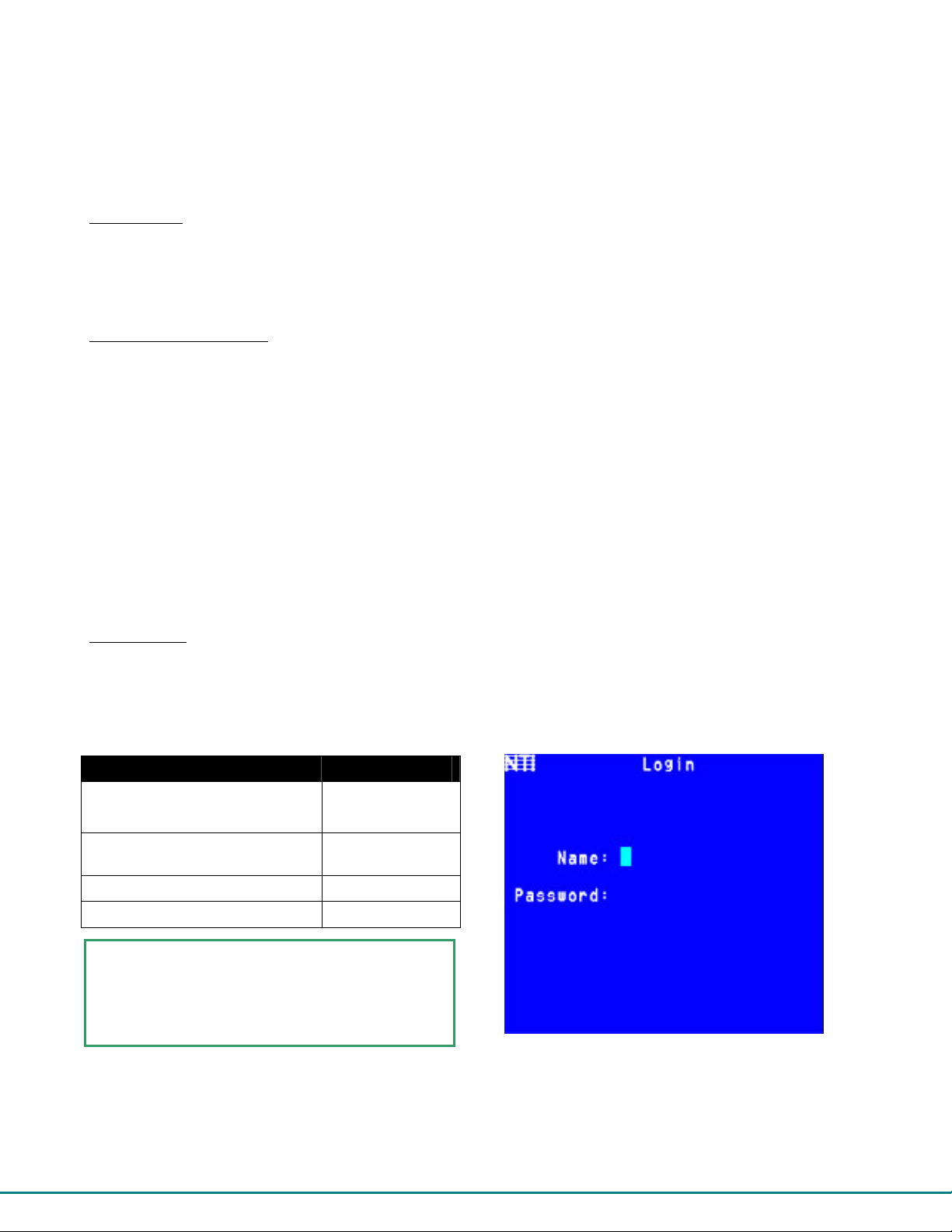
User Login
The administrator may configure the User Station to require each user to login using a predefined password to gain access to
CPUs and to the features in the OSD menus. Once logged-in, the user will be directed to the OSD menu where the user can
decide what action is to be taken.
Once logged-in, a user can use the Command Mode functions described below and on page 19 to control the CPUs within the
limitations as determined by the administrator.
Function Keystroke
Add a character to the user
name/password
Remove previous character from
the user name/password
Tabs to the next field
Submit user name/password/data
If the password submitted is incorrect, the user will
not be able to proceed.
If the password submitted is correct, the user will
proceed to the Command Mode menu.
Figure 16- Login splash screen
A-Z, 0-9
Max. 16 characters
Backspace
Tab
Enter
18
Page 24
Adapte
User OSD Menus
Command Mode
In order to control the User Station with the keyboard, Command Mode must be enabled. To enable C ommand Mode from the
keyboard:
Press
All the status lights on the keyboard will illuminate to indicate that Command Mode is enabled. At this point, the Command Mode
menu will be displayed.
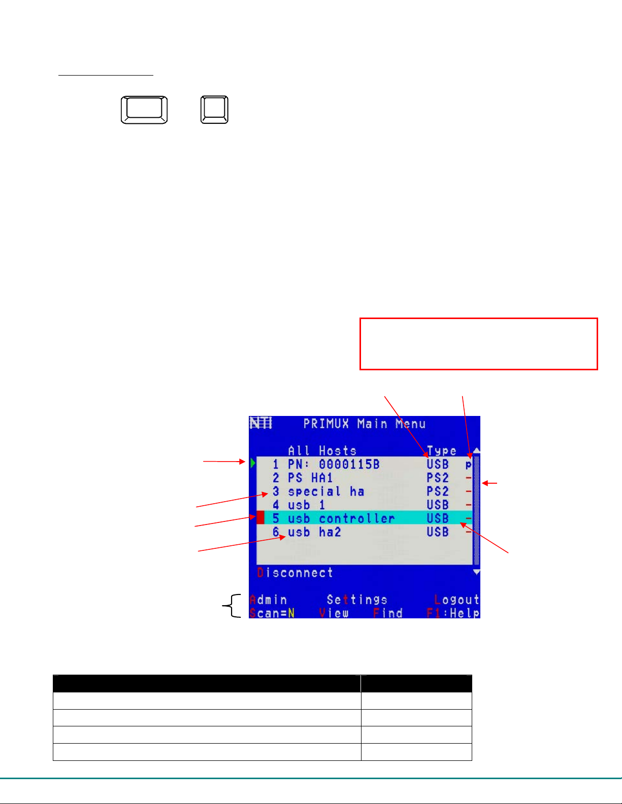
The Command Mode menu (see Figure 17) lists all Host Adapters by name and index number. Only 8 Host Adapters are listed on
the screen at a time. To view the other portions of the list, scroll using the arrow keys on the keyboard or use the mouse to click
on the arrows on the scroll bar in the OSD menu.
When the Command Mode main menu is first displayed at login, the first 8 Host Adapters will be displayed, sorted alphabetically.
When the Command Mode main menu is re-displayed to a logged-in user that has been w orking in a connected CPU, the Host
Adapters listed will be those in the same group of 8 as the CPU they are connected to (I.e., if they are connected to the Host
Adapter in index position 14, then Host Adapters 9-16 will be displayed when they reopen Command Mode). Alternatively, the
user can display only the Host Adapters they use most often, sorted as “Favorites” (see next page and page 24).
Only the names of Host Adapters accessible to the user that is logged-in will be displayed. The access rights for the user loggedin may not include all Host Adapters.
An arrow to the left of an index number in the list indicates the Host Adapter the user is currently connected to. From left to right,
the columns display the following:
• Index Number
• Host Adapter Name
• Type of Host Adapter connected (PS2,SUN, USB or SER)
• CPU power status (where "p" means ON and " - " means OFF)
Arrow indicates currently
connected Host Adapter
Ctrl
Index Number
Mouse Cursor
Host Adapter Name
+
(ACCENT/TILDE
~
`
`
KEY)
The CPU connected to a Host Adapter must be
powered-ON at least once while connected to the
daisy-chain and powered-ON User Station in order
to be included in the Command Mode list of CPUs.
Type of Host
r
CPU Power
Status
Scroll
Bar
Selection Bar
Figure 17- Command Mode main menu
The list below describes the command functions available from the keyboard within the OSD mode of control after entering into
Command Mode:
Function Keystroke
Select the previous Host Adapter
Select the next Host Adapter
Decreases the menu by 1 page (displays the previous 7 Host Adapters)
Increases the menu by 1 page (displays the next 7 Host Adapters)
Commands for submenus
Up Arrow
Down Arrow
Page Up
Page Down
19
Page 25

Function Keystroke
Display first 8 Host Adapters and move selection bar to the first
Display last 8 Host Adapters and move selection bar to the last
Press to toggle enable/disable Scan Mode
Enter Settings Menu
Enter Administration Mode (Administrator only- see page 26)
Find- select Host Adapter by name
Display Command Mode Help Menu
Connect to the highlighted Host Adapter
Toggle between listing all accessible Host Adapters and listing only
accessible “Favorite” Host Adapters
Disconnect from the currently connected Host Adapter- no CPU
connection will be displayed behind the OSD menu
Log Out the User/Administrator and disconnect from the Host Adapter
The login screen will appear (page 18)
Exit Command Mode without logging out
The mouse can also be used to control the User Station Command Mode.
• The scroll wheel can be used to scroll through the Host Adapters list.
• The mouse cursor can be moved to the any of the command fields where the user can click on
the left mouse button to select that function.
• Host Adapters listed on the screen can be selected by moving the cursor onto a Host Adapter.
• To connect to a Host Adapter, click on the selected Host Adapter.
• To move through the Host Adapter list, the scroll bar to the right of the list can be used by clicking the up and
down arrows.
Note: Exit Command Mode to enter Normal Mode and control the connected CPU. To exit Command Mode, press <Esc>.
Home
End
S
T
A
F
F1
Enter
V
D
L
Esc
Note: All Host Adapters must be programmed with firmware version 2.0 in order to work with a User Station programmed
with firmware version 2.0 and later. See “Please Note...” on page i.
Scan Mode
To activate Scan Mode press <S> from the Command Mode menu.
Scan Mode enables the user to scan through selected Host Adapters (unless they are powered-OFF) and to have full device
control of the connected powered-ON Host Adapter. From the Settings menu (page 21) the user can edit the list of Host Adapters
that can be scanned. A Host Adapter is skipped from the scan cycle if the Host Adapter is not selected in the scan list (page 23).
When switching to a new Host Adapter the Host Adapter name is displayed by OSD for 4 seconds. When the user moves the
mouse or types on the keyboard the scanned Host Adapter becomes active and scanning is stopped. The switch will resume
scanning after a period of user inactivity determined by the scan dwell time. The scan dwell time is programmable from 2 to 255
seconds (default time-out period is 5 seconds). See Settings Menu (page 21) for configuring the scan dwell time.
Note: The keyboard and mouse must remain idle for the full scan dwell time before the switch selects the next active
Host Adapter.
Normal Mode
When the User Station is not in Command or Scan mode and the OSD control menu is not active on the monitor, the us er is in
Normal Mode, controlling the CPU to which the user is connected through the PRIMUX switch.
20
Page 26

Settings Menu
The Settings Menu provides controls for how the current logged-in user will view and make the best use of the PRIMUX.
Note: Changes to Video Quality settings will effect all users of this User Station.
To enter the Settings Menu, press <T> from the Command Mode Menu.
Figure 18- Settings menu
Function Description Keystroke
OSD Settings Enables the user to reposition or resize the OSD
menu on the monitor
Host View Open field to toggle between a listing Host
Adapters alphabetically by name or just Favorites
by default when opening Command Mode
O
H
• Press <Spacebar> to toggle setting
• Press <Enter> or <Tab> to save
• Press <Esc> to cancel
Scan Dwell Time Enter field to set change Scan dwell time value
Hosts to Scan Choose CPUs to be scanned
Favorite Hosts Open listing of Host Adapters to be designated as
Favorites
Video Quality Adjust the video quality to improve the screen
image (must be connected to a Host Adapter to
use this)
Help Open Help window
Esc Exit the Settings menu
21
T
S
F
V
F1
Esc
Page 27

OSD Settings Menu
To enter the OSD Settings Menu, press <O> from the Settings Menu. (From the Command Mode menu press <T> - <O>.) Using
the OSD Settings, the user can resize and reposition the OSD window on the monitor as desired. Changes to the OSD settings
will only affect the logged-in user.
Figure 19- OSD Settings Menu
Function Description Keystroke
Move OSD Window Down Moves the OSD window down on the monitor
The default resolution of the OSD menu
is much lower than the average CPU
display setting. We recommend
adjusting the size of the OSD menu
before connecting to a CPU (i.e. make
adjustment immediately after powering
on the User Station, before connecting
to a CPU). Once a CPU connection is
made, the OSD menu will appear smaller
due to the higher resolution setting.
D or
Move OSD Window Up Moves the OSD window up on the monitor
Move OSD Window Right Moves the OSD window to the right on the monitor
Move OSD Window Left Moves the OSD window to the left on the monitor
Make OSD Window Taller Makes the OSD window taller on the monitor
Make OSD Window Shorter Makes the OSD window shorter on the monitor
Esc Exit the OSD Settings menu. Any changes are
automatically saved.
U or
R or
L or
T
S
Esc
Change Scan Dwell Time
The scan dwell time determines how long the PRIMUX will stay connected to a Host Adapter (in Scan Mode- page 20) while the
user is idle before switching to the next Host Adapter. When the <T> is pressed from the Settings Menu (From the Command
Mode menu press <T> - <T>), a field will appear around the current value for the scan dwell time. The user can enter any value
between 2 and 255 (seconds). The default scan dwell time value is 5 seconds.
Function Keystroke
Enter value
002-255
Save the new value Enter or
Tab
Exit
Figure 20- Scan Dwell Time field
Esc
22
Page 28
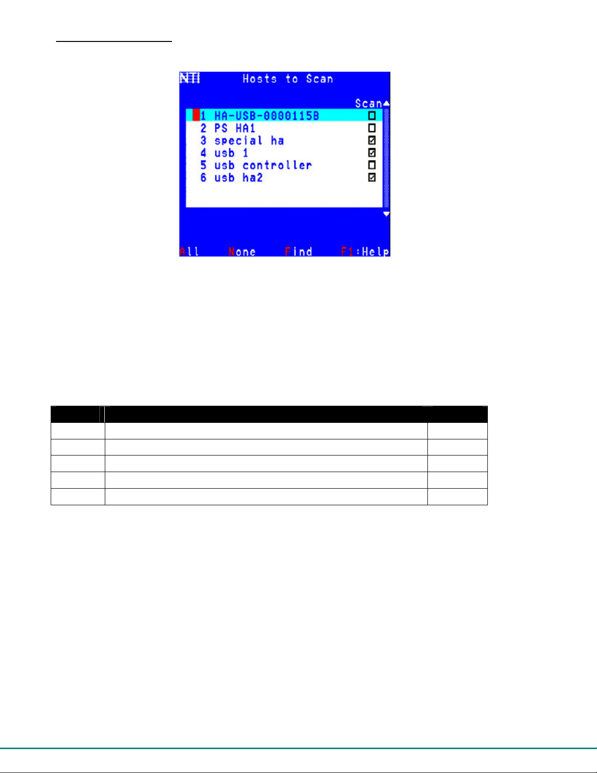
Select Hosts to Scan
From the Settings Menu, press <S> for the list of Host Adapters to select for scanning. (From Command Mode press <T> - <S>)
Figure 21- Host Adapters to Scan list
Scan Mode enables the user to scan through selected port s and to ha ve f ull devic e control of th e co nne cted port. F rom this men u
the user can select the ports that will be scanned.
Only the selected ports will be scanned in Scan Mode (page 20) when the respective user is logged in. Each user can hav e a
separate scan list.
A check list with all the Host Adapter index numbers and names followed by a check-box will be display ed in the window.
• unchecked box = the corresponding Host Adapter is not in the scan list
• checked box = the corresponding Host Adapter is in the scan list
The user can toggle the state of the selected check box by pressing <Spacebar> or clicking the Host Adapter with the mouse.
Function Description Keystroke
All Select all Host Adapters
None Clear all selected Host Adapters
Find Locate a Host Adapter by name
Display a Help Page for Hosts to Scan
Exit Return to the Settings Menu
A
N
F
F1
Esc
The scan selection list is automatically saved.
23
Page 29

Favorite Hosts
From the Settings Menu, press <F> for the list of Host Adapters to select as favorites. (From Command Mode press <T> - <F>)
The favorite hosts are typically those that a user connects to the most frequently. All accessible Host Adapters are listed and up
to 8 can be numbered 1-8. The numbers assigned will determine their order of listing on your F avorites list in the Command Mode
main menu, and which Front Panel buttons (where applicable- see page 17) will be asso ciated with which Host Adapters.
Favorite Host assignments are unique to each user profile.
Figure 22- Favorite Hosts list
Function Description Keystroke
---- Move selection bar up
---- Move selection bar up
---- Assign a position in the Favorite’s List or a Favorite button
---- Remove a position in the Favorites List or a Favorite button
None Clear all selected Host Adapters
Find Locate a Host Adapter by name
Help Display a Help Page for F avorite Hosts
---- Return to the Settings Menu
Note: If a number is assigned twice, the first listing with that number will lose its place in the list.
Up arrow
Down arrow
1 thru 8
Backspace
N
F
F1
Esc
24
Page 30

Video Quality Adjustment
Video quality adjustment is done automatically to assure the image is as clear as possible. However, due to the different twisting
rates of each pair of wires in the CAT5 cable, variations in the signal delays between the red, green, and blue channels will occur
when the cable is longer than 300 feet. This may also be caused by differences in cable types that can be used (i.e. shielded vs.
unshielded cable and CAT5 vs. CAT6 cable).
Video Quality Adjustment values are stored on a per Host Adapter-to-User Station basis. The settings made will apply to all users
for that Host Adapter-to-User Station connection. Adjustment may be necessary for each Host Adapter.
To display the Video Adjustment screen, press <V> from the Settings Menu. (From the Command Mode menu press <T>-<V>.)
An image with 6 horizontal bars (video components) will appear.
FYI: Video Quality
Adjustment may need
to be repeated if the
CAT5 cable is changed.
Figure 23- Video Adjustment Screen
Function Keystroke
To move between the scroll bars Up Arrow or Down Arrow or R, G, B, A or I or click on the row
To adjust the scroll bar setting Left Arrow or Right Arrow or click on the left/right arrow
Modify screen position Move the mouse beyond the image boundaries to drag the image
Exit menu and save
Esc
Note: Changes made to the settings affect the screen image as they are made.
Test Patterns for Color Skew Adjustment
To verify the need for and effect of color skew adjustment using a test pattern specifically designed for your
display setting, browse the CD this manual was found on and click on the “test-pattern -nXm.pdf” file that
matches your current video resolution. Follow the instructions below to make adjustments as needed.
The variations in signal delays could cause the colors to be skewed or out of alignment as they appear on the monitor (i.e . instead
of a white vertical line the user will see three vertical lines: red, green, and blue). These variations may be adjusted by changing
the settings of the “Red Skew”, “Green Skew”, or “Blue Skew” horizontal scroll bars. Changing the settings will vary the timing of
the signals and ultimately balance them out.
The "Sharpness" scroll bar is used for adjusting the crispness of the images and character s. This allows the user to "fine tune"
the quality of the adjusted video. FYI: Due to the extensive range of this feature, pressing and holding the left or right
arrow key down with this bar will move the adjustment slide more rapidly.
The “Brightness” scroll bar is used to adjust the brightness of the video image coming from the connected CPU through the Host
Adapter as it appears on the monitor. The PRIMUX will automatically set the brightness to a level that should be acceptable, but
the slide can be moved left or right if more adjustment for that Host Adapter is desired.
The “Comp.” scroll bar is use to adjust the video quality based on the varying twist rates and lengths of the CATx cable used.
FYI: For additional quality adjustment, it may be necessary to adjust the brightness and co ntrast settings of the monitor.
25
Page 31

Administrator Controls
Administration Menu
Note: The Administration menu will only be accessible if the administrator is logged in (page 18) or if the user h as
administration rights.
Press <A> from the Command Mode menu (page 19) to display the Administration menu.
Figure 24- Administration Menu
The table below describes the functions of the Administration menu.
Function Description Keystroke
System Configuration Edit settings like logoff timeout, alternate OSD key, OSD blank
timeout, etc. (page 27)
Host Configuration Edit Host Adapter names and properties (page 29)
User Configuration Lists the Users to be edited, shows the status of all users, and
provides option to Add/Delete users (page 32)
User Station Configuration Set auto-login user, User Station name, keyboard language, etc.
(page 34)
Firmware Configuration View code version, downloaded code, upgrade Host Adapters
(page 36)
Network Configuration
Esc Return to the Command Mode menu
*shown only in Matrix Mode*(page 34)- Edit the network settings
(page 40) of the PRIMUX Matrix
S
H
U
R
F
N
Esc
26
Page 32
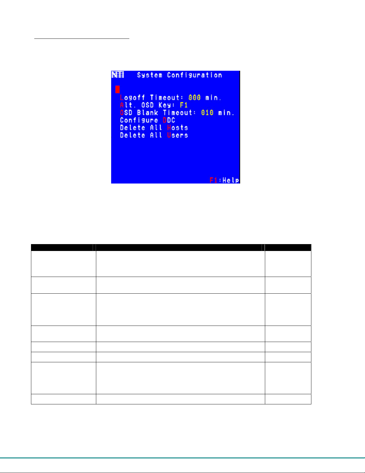
System Configuration Menu
Press <A> -<S> from the Command Mode menu to display the System Configuration menu.
Figure 25- System Configuration menu
Function Description Keystroke
Logoff Timeout Open an edit field to set the time in minutes after which a user will
be logged out of Command Mode due to inactivity.
Range= 0-255 minutes (value of 0 disables the feature)
Alternate OSD Key
OSD Blank Timeout Set the time in minutes for the OSD screen to blank out due to
Configure DDC Opens a Host Adapters list in which DDC can be sent from the
Delete All Hosts
Delete All Users
Sharing Timeout
Help Display topic specific help page
Define an alternative key to use with <Ctrl> to enter Command
Mode
inactivity- moving the mouse or pressing a key on the keyboard will
redisplay the OSD
Range= 0-255 minutes (value of 0 disables the feature)
monitor to specific host adapters
Deletes all Host Adapters listed-
Deletes all configured Users-
*
shown only in Matrix Mode*(page 34)- when a host is in full share
mode (page 29) , this is the time after which a user will relinquish
control so that another user may take control.
Range= 2-255 seconds
requires confirmation
requires confirmation
27
L – (000-
255)
A
I
D
H
U
F1
Page 33
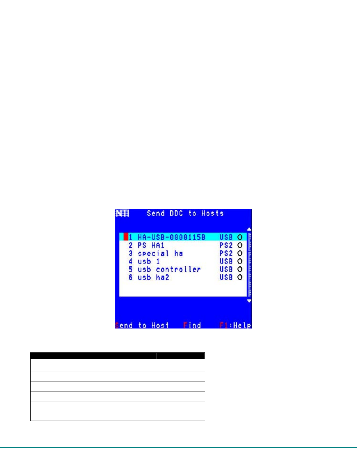
Alternate OSD Key
This function enables the administrator to assign a key in addition to the <`> (accent/tilde key) to use with <Ctrl> to enter into
OSD Command Mode. The default factory setting for this option is “Accent“ (disabling the option).
To assign an Alternate OSD key press <A> from the System Configuration Menu. (From Command Mode type <A>-<S>-<A>.)
An edit field will open displaying the current value. Type a key to be used with the <Ctrl> key to open command mode. Reenter <`> (accent/tilde key) to disable the feature.
FYI: The Alternate Command Hot Key does not replace the <`> (accent) key, it just works as an additional way to enter
into Command Mode. After setting it, the user can enter into Command Mode either with <Ctrl> + <`> or with <Ctrl> +
<Alternate OSD Key> combination.
Configure DDC-Auto Detect Resolutions
DDC information allows the CPU to automatically select the optimal resolution for the monitor by receiving, at pow er up,
information from the monitor concerning its resolution specifications.
The DDC information is acquired from the monitor by the PRIMUX. A monitor with DDC support must be connected to the
connector "MONITOR" on the User Station and be powered ON for this to occur. The DDC information will be sent to the
selected powered Host Adapter to be retrieved by its connected CPU.
Note: The CPU connected to the Host Adapter must be powered up to receive the DDC information.
DDC information is automatically acquired from the monitor by the User Station. To send DDC information to a powered Host
Adapter, press <D> from the System Configuration Menu. (From Command Mode type <A>-<S>-<D>.)
Figure 26- Configure DDC
Description Keystroke
Move the selection bar to the desired Host Adapter Up arrow or
Down arrow
Use the “Find” feature to locate the Host Adapter
Make a selection
Send DDC information to the selected Host Adapter
View help screen
Return to the System Configuration menu
F
Spacebar
S
F1
Esc
28
Page 34

Configure Host Adapters
From the Administration Menu, press <H> to display the Configure Host Adapters menu from which the adminstrator can select
Host Adapters to edit (From Command Mode type <A> - <H>.)
Figure 27- Host Adapter List
Function Description Keystroke
Find Locate a Host Adapter by name
Help Display topic specific help page
Exit Return to the Edit menu
Note: The HA-RS Host Adapter will only work with User Stations programmed with firmware version 2.0 and later.
F
F1
Esc
Note: All Host Adapters must be programmed with firmware version 2.0 in order to work with a User Station programmed
with firmware version 2.0 and later. See “Please Note...” on page i.
Edit Host Adapter
With a Host Adapter selected from the Host Adapter List, press <Enter> to bring up the Edit Host Adapter menu. (From
Command Mode type <A> - <E> - <H> -<Enter>.)
Figure 28- Edit Host Adapters menu
29
Page 35

To edit the Host Adapter enter the desired parameter values as defined in the chart below:
Suggestion: Use the <Tab> key to quickly jump between editable fields for easy configuration management.
Function Description Keystroke
Name Modify the name (of the selected Host Adapter)- opens
an edit field to enter a character string- 16 characters
max., case sensitive.
Press <Enter> or <Tab> to save
Press <Esc> to cancel
Mac Designate a Host Adapter to be connected to a Mac-
A checkmark in the box indicates Mac CPU
User Access
Controls
Share Mode
Delete Delete Host Adapter from Host Adapters list
Help Display topic specific help page
---- Return to Host Adapter List
FYI: When modifying the name, the position of that Host Adapter in the Host Adapter list will be adjusted according to
its alphabetical order. Index numbers will adjust accordingly.
FYI: When deleting a Host Adapter, all configurable settings including DDC information and the MAC configuration will
be removed. If a Host Adapter is deleted while connected, it must be disconnected from the CPU and reconnected in
order to be re-discovered by the User Station.
Open list of Users to select which users will have access
to this Host Adapter
*only shown in Matrix Mode* (page 34)- Configure
sharing for the Host Adapter. Options are None, Limited,
and Full.
M - Spacebar
S - Spacebar
N
U
D
F1
Esc
Configure MAC Host Adapters
Designating a Host Adapter for use with a MAC CPU enables the mouse to pass information to a con nected USB MAC CPU. This
is useful when the user wants to use mouse drivers provided by the mouse vendor, which allows the use of programmable
functions for each button. Host Adapters should be configured at installation time or whenever necessary. After setting, the
configuration is stored in non-volatile memory and will be retrieved whenev er the PRIMUX-UZR is power ON. When the Host
Adapter is connected to a Windows, SUN, or USB SUN CPU, this configuration SHOULD BE DISABLED. By default, all Host
Adapters are configured for connection to non-USB MAC CPUs (Windows and USB SUN).
FYI: If a Host Adapter is configured as connected to a non-MAC CPU, but is in fact connected to a MAC CPU, the mouse
will still work as a generic mouse. No special functions provided by software drivers will be available.
User Access Controls
The User Access Controls list enables the administrator to assign which users will have access to a specific Host Adapter.
Figure 29- User Access Controls list
30
Page 36
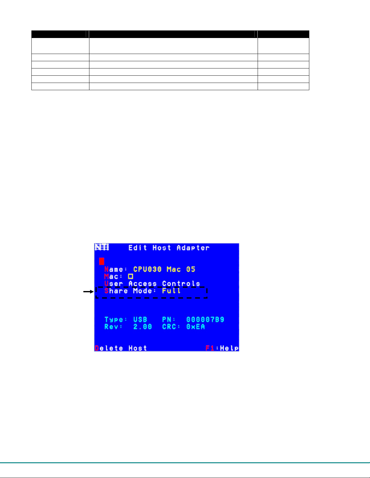
Function Description Keystroke
--- Move selection Bar
bar
--- Select specific user to access the Host Adapter
All Allow All Users to access the Host Adapter
None Allow No Users to access the Host Adapter
Help Display topic specific help page
Exit Return to the Edit menu
Note: Changes to these selections will effect the selections made in the Access Controls list for User (page 30).
Note: Users with administrative rights automatically have access to all Host Adapters, so access to the user “root” and
any users with administrative privileges cannot be de-selected.
Up arrow or
Down arrow
Spacebar
A
N
F1
Esc
Share Mode
Share mode is only available in Matrix Mode (page 34)
From the Edit Host Adapter menu, press <S> to toggle Share Mode between three possible settings:
None- only one user can access a host adapter at a time. Other users that try will receive a “Host in use” error message.
Limited- the first user to connect to the Host Adapter will gain control of the keyboard/mouse for the connected CPU until they
logout, disconnect from that Host Adapter, or change to a different Host Adapter. Other users can connect to the Host Adapter to
view the video, but no keyboard/mouse control will be allowed unless the first user gives up control.
Full- all users with access permission to that Host Adapter may compete for keyboard/mouse control. A user with control will
retain control until their keyboard/mouse is idle for the specified sharing timeout period (page 27). Control is then relinquished
and the first user to use their keyboard/mouse will gain control.
Figure 30- Share Mode Option (Matrix Mode only)
Keyboard/Mouse Access Indicators
A mouse and keyboard icon will appear in the upper left corner of the screen for a couple of seconds to indicate the status of the
keyboard/mouse control.
The icons will appear green when the user has control over the keyboard/mouse,
yellow when the keyboard/mouse control is available to the user (like in Limited and Full Share Modes),
red when the keyboard/mouse control is not available to the user.
31
Page 37

Configure Users
From the Administration Menu, press <U> to display the Configure Users menu from which the adminstrator can select Users to
add or edit (From Command Mode type <A> - <U>.) The Configure User menu displays from left to right 1) the name of each
user, 2) whether or not the user has been assigned administrative rights and 3) whether they are enabled to login or not. From
this menu the administrator can also add new users.
Figure 31- Configure Users menu
Function Description Keystroke
---- Select User to be edited
---- Open User Edit menu
Add New User Add new user and open User Edit menu
to configure User options-
Y / N Confirmation required
Help Display topic specific help page
---- Return to Administration menu
Up arrow or
Down arrow
Enter
A - Y/N
F1
Esc
Enabled to login
Administrative rights are
assigned
Edit Users
From the Configure Users menu, press <Enter> to select a user to edit and bring up the Edit User menu. (From Command
Mode type <A>-<U>- select a user and press <Enter>)
Figure 32- Edit Users menu
32
Page 38

Function Description Keystroke
Name Modify the name (of the selected User)- opens an edit field to enter a
character string- 16 characters max., case sensitive.
Press <Enter> or <Tab> to save
Press <Esc> to cancel
Enabled Allows the administrator to enable a user to login or not to login to the User
Station. A checkmark in the box indicates the user is enabled.
Admin
Privileges
Host Access
Controls
Password Opens an edit field to enter a password for that user. 16 characters max. -
Confirm Opens an edit field to re-enter a password for that user. Must be entered
Delete User
Help Display topic specific help page
Exit Return to the Configure Users menu
• If no password is entered in th e “Password” field, a message “Press Enter for blank password” will appear when you open the
“Confirm” field. Press <Enter> for that user to login without submitting a password at the login prompt.
• If the <Esc> key is pressed to exit while entering the Password or Confirming, no change to the password will be made.
• If no password is assigned to a user when a user is added, that user will login without the need for a password.
Note: The user “root” is special. Its name, enabled status, privileges, and host access cannot be changed. Only root’s
password can be changed from the default “nti”.
Allows the administrator to assign a user to have administrator rights or not.
A checkmark in the box indicates the user has administrative privileges.
Brings up a list of Host Adapters to assign user access to
case sensitive-
- Press <Enter> to save
- Press <Tab> to save and move to next field
exactly as it was entered in Password field
- Press <Enter> to save
- Press <Tab> to save and move to next field
Delete User from Users list-
Y / N Confirmation required
N
E -
Spacebar
A -
Spacebar
H
P
C
D
F1
Esc
Add New User
From the Configure Users menu press <A> to add a new user. (From Command Mode type <A> - <U> - <A>.) The administrator
will be prompted for a "Y" or "N" answer to "Are you sure?" and with a "Y" answer the Edit User menu will come up where all of
the parameters for a new user can be defined. When finished, press <Esc> to exit the menu and the new user “NEW USERx”
will have been added to the User List.
By default, a new user will be given no access to Host Adapters. To change this, the administrator must edit the user host access
list as described on page 33.
Host Access Controls
To define what CPUs a specific user has access to, press <H> from the Edit User List (page 32). (From Command Mode press
<A> -<U> - select a user (other than “root”) and press <Enter> - <H>.) The "Host Access Controls” list will be displayed.
FYI- Access Controls list can also be applied from the User Access Controls men u. (From Command Mode press <A> <H>-Select Host Adapter-<Enter>-<U>). The User Access Controls list includes a list of Users to select to have access
to a specific Host Adapter. Changes made in either access controls menu will effect selections in both menus.
Note: Users with administrative rights automatically have access to all Host Adapters, so the Host Access Control list is
not present to edit for those users.
33
Page 39

Function Description Keystroke
---- Toggle Specific selection
Find Locate H ost Adapter b y name
All Allow user access to all Host
Adapters
None Allow user access to no Host
Adapters
Help Display topic specific help page
---- Esc
Spacebar
F
A
N
F1
Esc
Figure 33- Host Access Controls list
User Station Configuration
From the Administration menu (page 26) press <R> to bring up the User Station Configuration menu. (From Command Mode
press <A> - <R>.)
Note: The “Mode” setting
should be left as “Standalone” whenever the User
Station is being used by itself.
Only set it to “Matrix” if the
User Station will be used in
conjunction with a PRIMUX
Matrix Multi-User KVM Switch.
If this setting is changed to
“Matrix” by mistake, contact
NTI for instruction to return
the setting to “Stand-alone”.
Figure 34- User Station Configuration screen
To edit the User Station Info use the commands and enter the desired parameter values as defined in the chart below:
Suggestion: Use the <Tab> key to quickly jump between editable fields for easy configuration management.
Function Description Keystroke Parameter Value
Name Modify the name (this only has a practical
purpose when the User Station is in Matrix
Mode.)
Set Keyboard Language Set the keyboard language for use with the
CPU
Auto-login Select the Auto-login user to be
automatically logged in at power up
Mode Choose User Station mode
See “Note” above
Help Display topic specific help page
---- Return to Administration Menu
N
K
A
M + Spacebar
F1
Esc
String, 16 characters max., case
sensitive
None. Brings up Keyboard
Languages menu. Choose from list.
None. Brings up Select User menu.
Toggle between “Stand-alone” and
“Matrix”
Y / N Confirmation required
None
None
34
Page 40

Select Auto-login User
From the User Station Configuration menu, press <A> to bring up the Auto-login User list. (From Command Mode type <A> - <R>
- <A>.)
Figure 35- Select user for Auto-logIn
To select a user to be automatically logged-in when the User Station is powered-up, choose one of the actions listed below:
Function Description Keystroke
---- Select the user indicated by the selection bar (user2 is selected as
the auto-login user in the image above)
None Disable auto-login. A login prompt will be shown at power up
instead of Command Mode.
Help Display topic specific help page
---- Return to User Station Configuration Menu
Caution: Selecting a user with administrative privileges will leave system configuration completely open.
Enter or Space
N
F1
Esc
35
Page 41

Firmware Configuration Menu
The Firmware Configuration Menu is provided to enable the administrator to update the firmware inside the PRIMUX User Station
and Host Adapters as new or improved features are available. The updated code can be downloaded from the NTI website at
www.networktechinc.com\kvmswitch-cat5.html
Adapters.
From the Administration Menu press <F> to get to the Firmware Configuration Menu. (From Command Mode press <A> - <F>.)
Figure 36- Firmware Configuration Menu
The functions of this menu are as follows:
Function Description Keystroke
User Station Version Displays the latest firmware version of this User Station
Last Downloaded Image Displays the CODE IMAGE info of the last code that was
downloaded to the User Station using the Bootloader
program
Update Host Adapters To send the downloaded firmware image to a Host Adapter
selected from a list of Host Adapters (page 38)
Go to Bootloader To leave the OSD menu and activate the Bootloader
Program***. The Bootloader program is used to download
firmware images and update the firmware in the User Station.
A serial terminal*** must be connected to the "RS232"
serial port of the User Station to continue operation
Confirmation required- the user will be prompted with
a "Are you sure? (Y/N)" before acting on the command.
Press <Y> to continue, or <N> to cancel.
Save Configuration Save the system configuration file to a location on a
connected PC using HyperTerminal
Restore Configuration Restore a saved system configuration file from a location on
a connected PC using HyperTerminal
Help Display topic specific help page
---- Return to the Administration menu
***See the instructions included with the updated code downloaded from the NTI website (www.networktechinc.com\kvmswitch-
cat5.html) for additional information on the Bootloader Program.
Updated code and instructions for using the features above are included with the downloaded file from the NTI website.
. This section describes how to update the firmware in the User Station and Host
U
L
P
B
S
R
F1
Esc
36
Page 42

T
Save and Restore Configuration
To use the Save Configuration or Restore Configuration features you must first have a computer with a terminal emulation
program (i.e. HyperTerminal) attached to the User Station using the Null Modem cable included with your PRIMUX. Also, the
PRIMUX-UZR must be in Stand-Alone mode (page 34).
1. Attach the DINT-6-FF 9-pin serial null modem cable (supplied) between the serial port on the computer and the SERIAL port on
the PRIMUX.
his feature works in Stand-Alone mode only (page 34)
Figure 37- Connect null modem cable
2. Open the terminal emulation program (HyperTerminal) on the computer.
3. Connect to the User Station through the proper COM port using the following settings: 9600,8,n,1, no flow control.
To Save the Configuration:
With a connection made to the PRIMUX, press <S> from the computer with the OSD menu to select “Save Configuration”.
From the terminal window, go to the Transfer Menu, select Receive, and decide where to save the configuration file on the PC
(using Xmodem protocol) and then determine what to name the configuration file. While the file is being saved, the terminal will
display a status page and the message (in the OSD screen) “Saving Configuration” will be displayed. When finished, the
message “Configuration Saved” will be displayed.
To Restore the Configuration:
With a connection made to the PRIMUX, press <R> from the computer with the OSD menu to select “Restore Configuration”.
From the terminal window, go to the Transfer Menu, select Send (using Xmodem protocol), and browse to the saved configuration
file on the PC. While the file is being restored, the message “Restoring Configuration” will be displayed. When finished, the
message “Configuration Restored” will be displayed.
37
Page 43

The following error messages may be displayed for the reasons shown:
Error Message Reason
“Error Saving Configuration” Took too long to connect to the terminal
“Serial Communication Error” serial cable disconnected
“Configuration File Size Error” wrong file selected to restore
“Configuration File Type Error” wrong file selected to restore
Update Host Adapter Firmware
To use the “Update Host Adapters” command, the image downloaded using the bootloader (previous page) must be for either a
HA_USB, HA_PS2, or HA_SUN. The type of image downloaded into the bootloader will be shown. If the image is not for a
Host Adapter, the word “INVALID” will be shown.
Note: The HA-RS Host Adapter will only work with User Stations programmed with firmware version 2.0 and later.
Note: All Host Adapters must be programmed with firmware version 2.0 in order to work with a User Station programmed
with firmware version 2.0 and later. See “Please Note...” on page i.
Figure 38- Update Host Adapters
When updating a Host Adapter, the downloaded image must match the type of Host Adapter selected:
Host Adapter Type Downloaded Image needed (firmware file)
USB PRIMUX_HA_USB_x_x.b01 (where x_x is the version)
PS/2 PRIMUX_HA_PS2_x_x.b01
SUN PRIMUX_HA_SUN_x_x.b01
SER (RS) PRIMUX_HA_RS_x_x.b01
- Press <P> from the Firmware Configuration menu. The Host Adapter List will appear.
- Press the <Up arrow> or <Down arrow> to select the Host Adapter to be upgraded (or press <F> to use the
“Find” Feature to assist locating the desired Host Adapter).
- Press <Spacebar> to toggle the radio button to lock in the selection. Make sure the Host Adapter selected matches the
type of image downloaded.
- Press <U> for “Update Host” to send the firmware to the selected Host Adapter. An indication of percentage of transfer
will appear. At 100% the update will be complete. If the Host Adapter selected is not powered, inaccessible, or just not
functioning properly, an error will be displayed.
38
Page 44
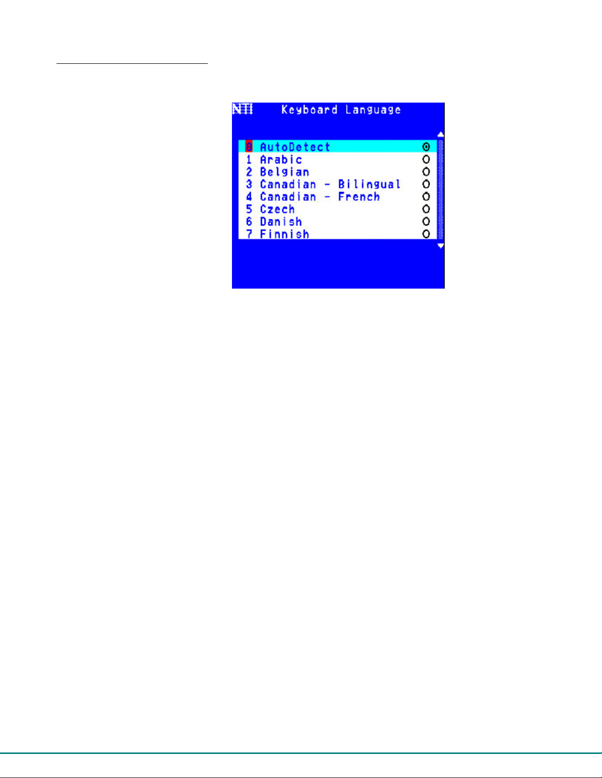
Select Keyboard Language
To enter the Select Keyboard Language menu press <K> from the User Station Configuration menu (from Command Mode pr ess
<A> - <R> - <K>).
Figure 39- Select Keyboard Language menu
The Select Keyboard Language menu enabl es the user to select a specific langu age (country code) to be used. Typically only
SUN CPUs require a specific country code to be registered at boot up. (For other types of CPUs this feature may have no effect.)
A list of available languages is displayed and can be scrolled using the mouse (scroll wheel) and/or <up arrow>, <down
arrow>, <Page up>, <Page down>, <Home> and <End> keys.
The language listing having a radio button with a dot in the center is the currently selected language for the keyboard.
• To manually program a specific keyboard language, select a language and press <Spacebar>.
• To have the User Station automatically detect the language of the keyboard, select "AutoDetect" and press <Spacebar>.
The list will advance to the actual detected keyboard language and that language wi ll be programmed.
Some keyboards don’t have a country code. In this case the selection will remain in the “AutoDetect” position and the default
country code "00" will be programmed in the Host Adapter. If a specific country code is manually programmed, it will be the
country code for the Host Adapter, regardless of the actual country code of the connected keyboard. The programmed country
code is saved in memory and restored each time the User Station is powered-ON. Because the CPUs that use country code (i.e.
SUN CPUs) read it at boot time, it is necessary to reboot the CPU(s) after programming the country code.
Press <Esc> to return to the User Station Configuration menu.
39
Page 45
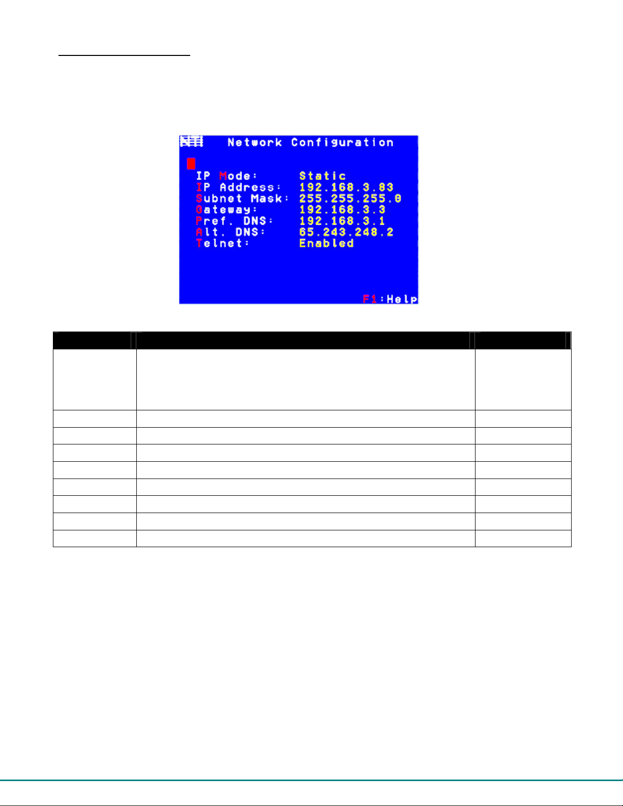
Network Configuration
This screen is only available in Matrix Mode (applicable when used with a PRIMUX Matrix Multi-User KVM Switch)- see
page 34 to change to Matrix Mode.
From the Administration Menu press <N> to get to the Network Configuration Menu. (From Command Mode press <A> - <N>.)
To enable the PRIMUX Matrix to be accessible via Telnet, the IP Address, Gateway, and DNS settings must first be configured.
Figure 40- Network Configuration page
Function Description Keystroke
IP Mode Toggle, using the <Spacebar> between “Static” or “DHCP”.
- In “Static” mode, the user must fill in all appropriate IP settings.
- In “DHCP” mode, the DHCP server will fill all IP settings in
automatically.
IP Address Open a field to enter an appropriate IP address (default is 192.168.1.22)
Subnet Mask Open a field to enter an appropriate subnet mask
Gateway Open a field to enter an appropriate gateway
Preferred DNS Open a field to enter a preferred DNS address
Alternate DNS Open a field to enter an alternate DNS address
Telnet Toggle telnet access between enabled and disabled
Help Open topic specific help page
---- Exit and return to the Administration Menu
M-Spacebar
I
S
G
P
A
T- Spacebar
F1
Esc
40
Page 46
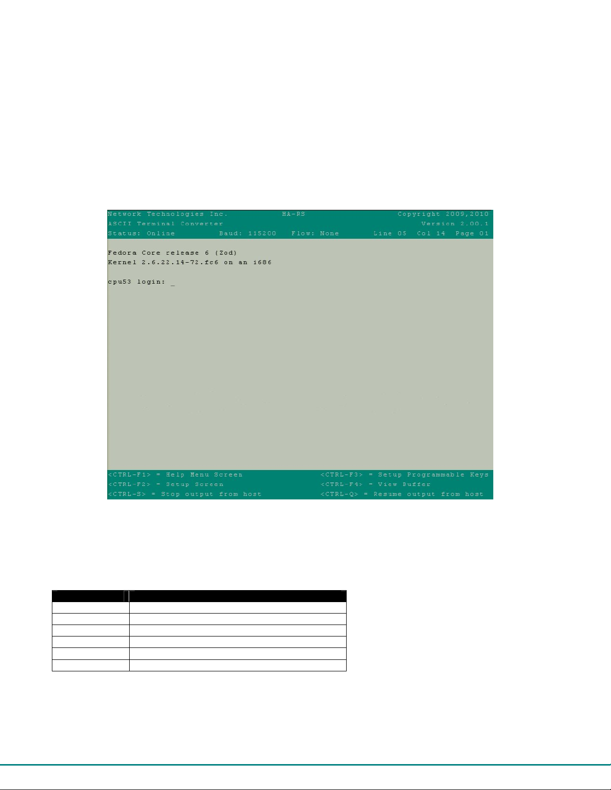
HA-RS Configuration
The HA-RS Serial Host Adapter enables a user to remotely connect to a serial device and control the device using the PRIMUX
User Station as a terminal. The HA-RS is compatible with most serial devices with an RS232 port. The HA-RS emulates a
VT100 terminal – converting serial data from an ASCII device into VGA video (800x600 @ 60Hz signal).
Note: The HA-RS Host Adapter will only work with User Stations programmed with firmware version 2.0 and later.
Note: All Host Adapters must be programmed with firmware version 2.0 in order to work with a User Station programmed
with firmware version 2.0 and later. See “Please Note...” on page i.
When connecting to an HA-RS through Command Mode (page 19) a terminal screen will be presented with a connection to the
serial device. The terminal screen will include available functions for the user interface listed at the bottom.
Figure 41- HA-RS User Interface
The user can either communicate to the serial device or use the <Ctrl> key in conjunction with <Fx> keys to control the colors of
the interface, the connection parameters of the HA-RS, or view up to 10 pages of data that has been viewed through the HA-RS
from the serial device. Control options are as follows:
Key Strokes Function
<Ctrl>-<F1> Help Menu
<Ctrl>-<F2> Setup Screen to setup connection parameters
<Ctrl>-<F3> Setup Programmable keys
<Ctrl>-<F4> View the stored data in the buffer
<Ctrl>-<S> Stop displaying output from host (serial device)
<Ctrl>-<Q> Resume displaying output from host (serial device)
41
Page 47
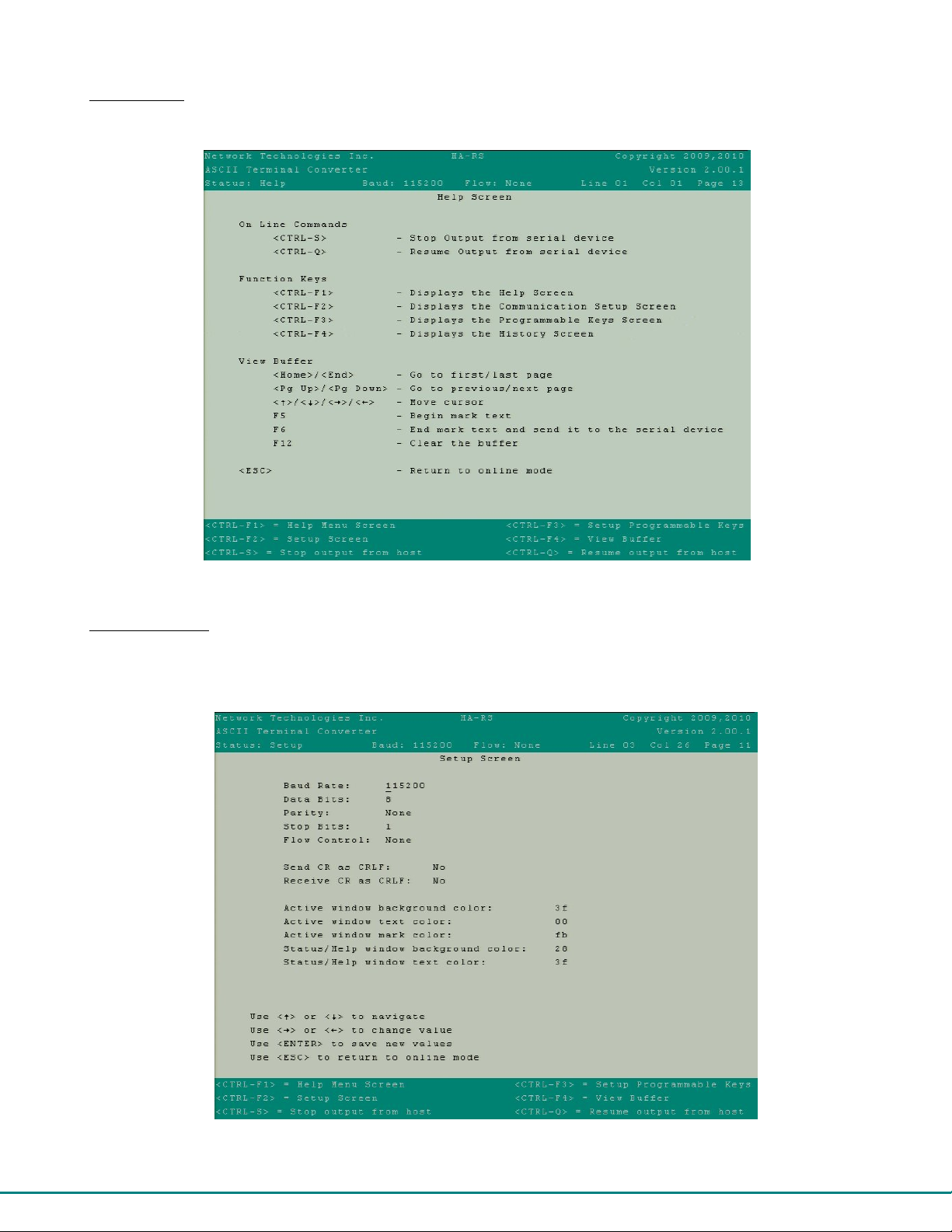
Help Menu
Press <Ctrl>-<F1> to view a list of information that will help you to navigate the features of the HA-RS host adapter.
Figure 42- HA-RS Help Screen
Setup Screen
Press <Ctrl>-<F2> to access a list of connection parameters and window color controls. The connection information shown
must match the required connection criteria of the serial device in order to connect to it.
Figure 43- HA-RS Setup Screen
Window color controls are available to change the look of the user interface as desired.
42
Page 48

Programmable Keys
A list of <Fx> keys that when used in conjunction with the <Alt> key can be programmed to be used as macro keys to send
commands to the connected serial device. When applicable commands are associated with an <Fx> key, pressing <Alt>-
<Fx> will send that command automatically to the serial device. In the example below, pressing <Alt>-<F1> will automatically
send the “logout” command.
Figure 44- HA-RS Programmable Keys Screen
View the Buffer
Press <Ctrl>-<F4> to view the last 10 pages of data that was received from the serial adapter. Once the buffer is full, the oldest
data in history will automatically be deleted to make room for new. The lines of text can be cleared from the history in their
entirety by pressing <Ctrl>-<F12> .
Stop and Resume Output
Press <Ctrl>-<S> to stop viewing the data received by the serial device. This will not stop the device from sending data, it will
simply stop you from seeing it.
Press <Ctrl>-<Q> to resume viewing the data received by the serial device.
43
Page 49
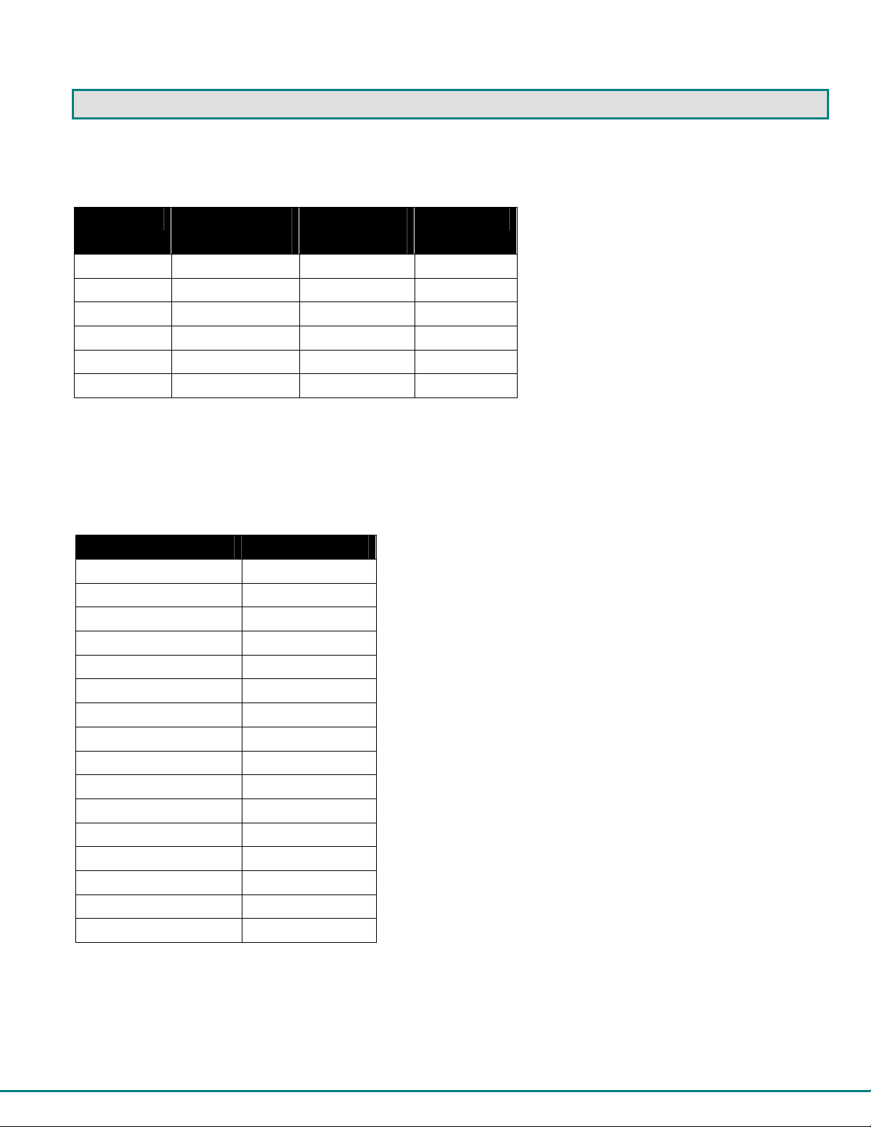
KEYBOARD MAPPING
Key Equivalents
Using the chart below, find the character needed to be typed on the CPU being accessed, then follow the row across for the
equivalent on the keyboard being used. (See Figure 45 on page 45 for reference.)
USB 101 PS/2
(Windows)
L-Ctrl L-Ctrl L-Ctrl L-Ctrl
L-Alt L-Alt L-Option L-Alt
SB+F12 Application SB+F12 Compose
R-Alt R-Alt R-Option Alt-Graph
SB+Alt Windows Logo Command Meta
SB+R Arrow SB+R Arrow Power Suspend
SB = Space Bar
L and R = Left and Right keys when two keys are marked the same on a keyboard.
MAC
(Apple USB)
SUN
SUN’s 16 Extra Keys
PS/2, USB Keyboards SUN Extras
SB+F1 Stop (L1) Use the chart to the left to type SUN’s
SB+F2 Again (L2) additional 16 keys using a PS/2 or
SB+F3 Props (L3) USB keyboard
SB+F4 Undo (L4)
SB+F5 Front (L5)
SB+F6 Copy (L6)
SB+F7 Open (L7)
SB+F8 Paste (L8)
SB+F9 Find (L9)
SB+F10 Cut (L10)
SB+F11 Help
SB+F12 Compose
SB + Up Arrow Vol +
SB + Down Arrow Vol -
SB + L Arrow Mute
SB + R Arrow Suspend SB= Space Bar
44
Page 50
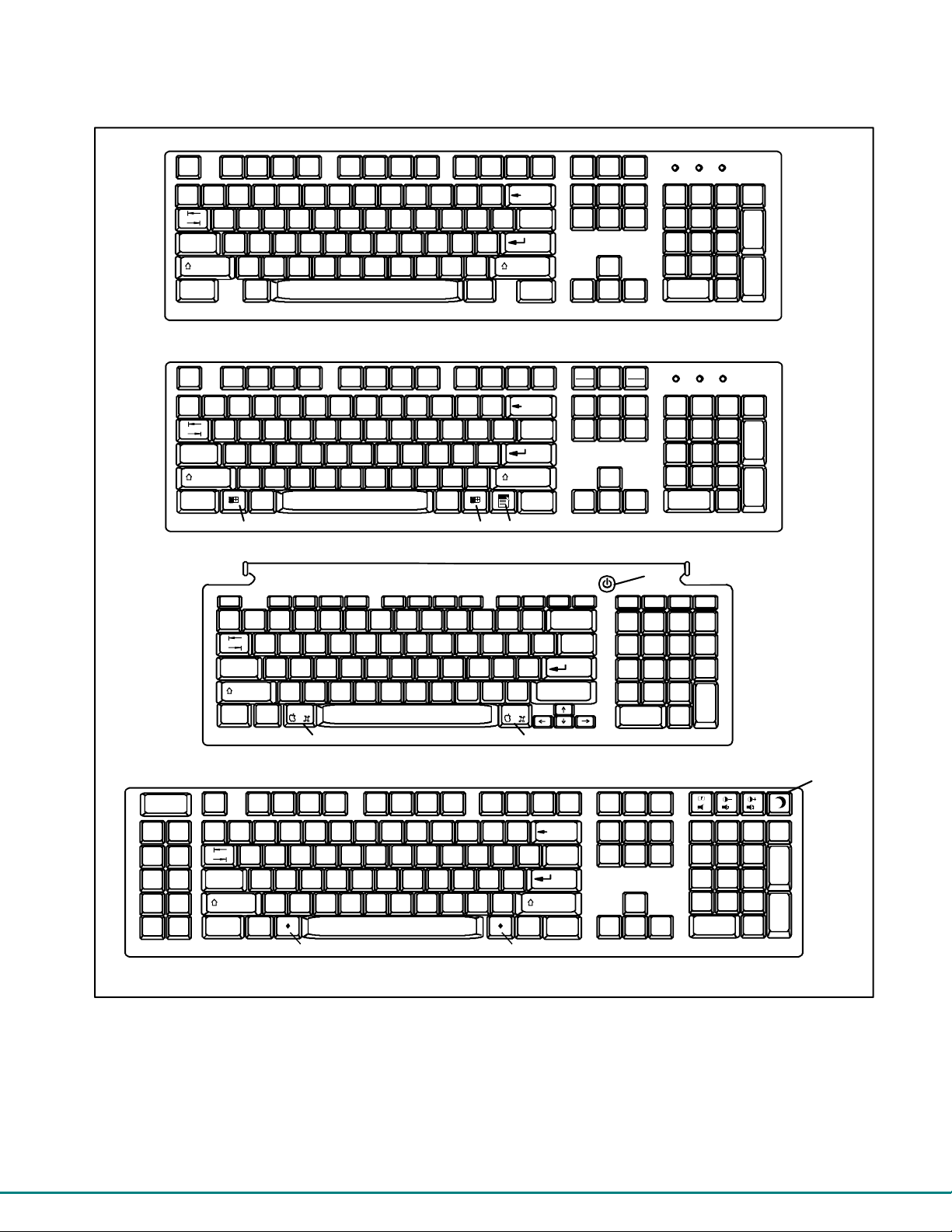
Esc
~
`
Tab
Caps Lock
Shift
Ctrl Alt
Backspace
Enter
Shift
Alt
Ctrl
Esc
F1 F2 F3 F4 F5 F6 F7 F8 F9 F10 F11 F12
~
`
Tab
Caps Lock
Shift
Ctrl Alt
Windows Logo Ke y
Typical 101 Keyboard
Backspace
Enter
Shift
Alt
Ctrl
Application KeyWindows Logo Key
Windows Keyboard
esc
~
`
tab
caps Lock
control
delete
return
shift
alt
option
Command Key
Command Key
Apple USB Keyboard
Help
Stop
Props
Front
Open
Find Cut
Again
Undo
Copy
Paste
Esc
Tab
Caps Lock
Shift
Ctrl Alt
Enter
Shift
Compose
Meta Key Meta Key
Backspace
Alt
Graph
SUN USB Keyboard
Figure 45- Keyboard layouts
Print
Screen
SysRq
F12 F11 F9 F10 F8 F7 F6 F5 F4 F3 F2 F1
Scroll
Lock
Num
Lock
Pause
Break
Num
Lock
Power
Button
help home pg up pg dn
num
lock
=/
clear
Num
Lock
*
enter
Enter
Enter
Suspend
key
Enter
45
Page 51
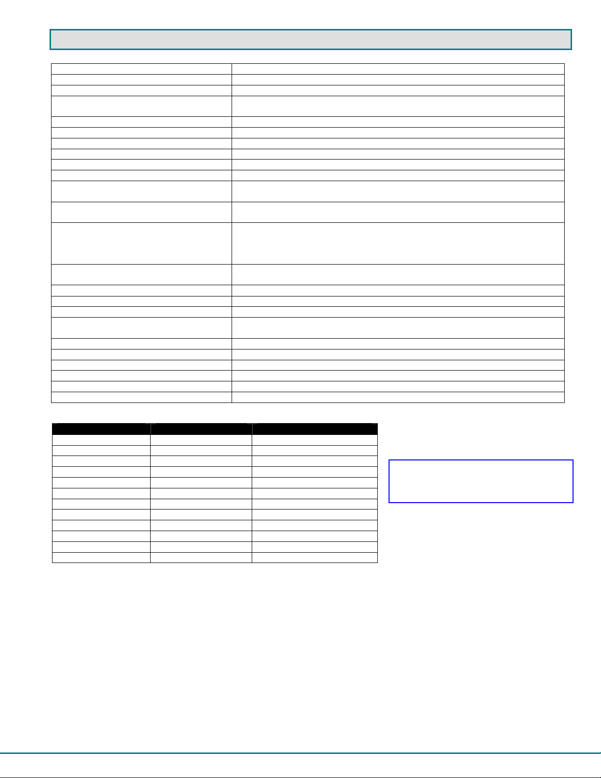
TECHNICAL SPECIFICATIONS
Video Compatibility SVGA, XGA, VGA
Video Quality Adjustment Automatic, for up to 1000 feet of CAT5 cable
Video Coupling DC
Video Connectors HD15 male to CPU
HD15 female to monitor
Maximum Input/Output Levels 1.45Vp-p (no offset)
Input / Output Impedance 75 ohms
Input Horizontal Frequency Range 15kHz to 130 kHz
Input Vertical Frequency Range 30 Hz to 150 Hz
Maximum Baud rate (HA-RS only) 115200 bps
Support RS232 Signals (HA-RS only) TXD,RXD,DSR,DTR,CTS,RTS
Terminal emulation (HA-RS only) ASCII to VGA (800x600@60Hz, 80 characters wide x 30 lines high)- supports
VT100 emulation
User Keyboard/Mouse Connectors Female 6 pin miniDIN
Female USB Type A
CPU Keyboard/Mouse Connectors Male 6 pin miniDIN to device ports for PS/2 CPU
Male USB-Type A to device port for USB CPUs
Male 8 pin miniDIN to devices port for Legacy SUN CPU
Male RJ45 and USB Type A Male to console ports on serial devices
Mouse and Keyboard Compatibility Most PS/2 mice and keyboards
Most USB mice and keyboards
CPU Compatibility PS/2, Legacy SUN, USB SUN, USB MAC, Serially-Controlled servers/devices
Keyboard and Mouse Current Rating 500mA maximum
Sync Types Supported Separate and composite TTL Level
Mean Time Between Failures (MTBF) User Station: 72,786 hrs
Host Adapters: 316,996 hrs
Regulatory Approvals CE, RoHS
Interconnect Cable CAT 5/5e/6 Solid UTP/STP EIA/TIA 568 B wiring w/ male RJ45 connectors
Host Adapter Power Powered by CPU
User Station Power 5VDC/2.0A via 120V or 240V at 50 or 60Hz AC Adapter
Host Adapter Size (In.) WxDxH 3.1 x 3.7 x 1
User Station Size (In.) WxDxH 11 x 11 x 1.75
Distances and Resolutions for CAT5/CAT5e and CAT6 Cables
CABLE DISTANCE (feet) RESOLUTION
CAT5/CAT5e (UTP) 1000 1024x768 at 60Hz
CAT5/CAT5e (UTP) 700 1280x1024 at 60Hz
CAT5/CAT5e (UTP) 500 1600x1200 at 60Hz
CAT5/CAT5e (UTP) 400 1920x1440 at 60Hz
CAT5/CAT5e (STP) 600 800x600 at 60Hz
CAT5/CAT5e (STP) 500 102 4x768 at 60Hz
CAT5/CAT5e (STP) 300 128 0x1024 at 60Hz
CAT5/CAT5e (STP) 100 192 0x1440 at 60Hz
CAT6 (UTP) 800 1024x768 at 60Hz
CAT6 (UTP) 600 1280x1024 at 60Hz
CAT6 (UTP) 500 1600x1200 at 60Hz
CAT6 (UTP) 350 1920x1440 at 60Hz
Note: Actual resolution may vary
depending upon the construction of the
CAT5 cable used.
46
Page 52
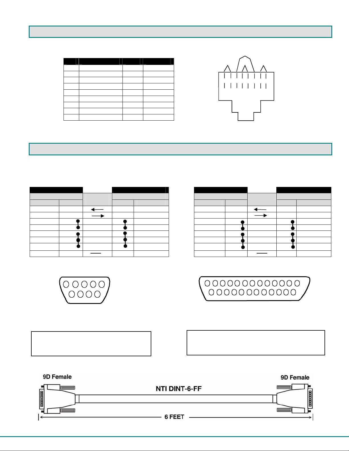
INTERCONNECTION CABLE WIRING METHOD
The CAT5 connection cable between the remote and local is terminated with RJ45 connectors and must be wired according to the
EIA/TIA 568 B industry standard. Wiring is as per the table and drawing below.
Pin Wire Color Pair Function
Pair 3
Pair 2 Pair 1
Pair 4
1 White/Orange 2 T
2 Orange 2 R
3 White/Green 3 T
T
T
R
R
T
R
R
T
4 Blue 1 R
5 White/Blue 1 T
6 Green 3 R
4
+
-
5
+
-
+
8
6
7
+
-
-
3
1
2
7 White/Brown 4 T
8 Brown 4 R
SH Drain wire - Shield
Figure 46- View looking into RJ45 female
NULL MODEM CABLE PINOUTS
An NTI DINT-6-FF 6 foot null modem cable has been supplied to make connection between your PC terminal and the PRIMUX in
order to perform firmware upgrades or save and restore configuration files. The pinouts for this cable are detailed below should
you wish to make a longer cable (not to exceed 15 feet).
PRIMUX to Terminal (9 PIN) null modem cable PRIMUX to Terminal (25 PIN) null modem cable
PRIMUX TERIMINAL PRIMUX TERMINAL
9 pin Signal 9 pin 9 pin Signal 25 pin
Function Pin # Direction Pin # Function
RxD 2 3 TxD RxD 2 2 TxD
TxD 3 2 RxD TxD 3 3 RxD
CTS 8 N/C 7 RTS CTS 8 N/C 4 RTS
RTS 7 N/C 8 CTS RTS 7 N/C 5 CTS
DSR 6 N/C 4 DTR DSR 6 N/C 20 DTR
DTR 4 N/C 6 DSR DTR 4 N/C 6 DSR
DCD 1 N/C 1 DCD DCD 1 N/C 8 DCD
SG 5 5 SG SG 5 7 SG
N/C= not connected (no cable wire)
In this cable signals CTS and RTS are connected to each other at the connector ends, and
signals DSR, DTR, and DCD are connected to each other at the connector ends.
1
345
2
6
8
9
7
NTI Parts to make:
DB9F-SLDR (X2) + DB9-HOOD-SHLD (X2) +
Any 20-24AWG 3-wire cable
Mating Face
of 9D
Male Connector
Note: Cable length not to exceed 15ft.
Function Pin # Direction Pin # Function
13
25
1
14
Mating Face
of 25D
Fema le C onn ect or
NTI Parts to make:
DB25F-SLDR + DB9F-SLDR + DB25-HOOD-SHLD +
Any 20-24AWG 3-wire cable
47
Page 53

MENU QUICK-FIND KEYSTROKE TABLE
Function Source Page Keystroke Sequence
Command Mode 19
Return to Command Mode 16
Administration Menu 26
Activate Scan Mode 20
Settings Menu 21
OSD Settings Menu 22
Host Adapters for scan 23
Change scan dwell time 21
Favorite Host Adapters selection 24
Video Quality Adjustment 25
System Configuration Menu 27
Change Logoff timeout 27
Set alternate OSD key 28
Configure DDC info 28
Configure Host Adapters 29
Edit Host Adapter 29
Configure MAC Host Adapter 30
User Access Controls 30
Enable Share Mode (Matrix Only) 31
Delete Host Adapter 31
Configure Users 32
Edit User 32
Edit User/Administrator Password 32
Add New User 33
Host Access Control 33
User Station Configuration 34
Select Auto-login User 35
Firmware Configuration Menu 36
Update Host Adapter Firmware 37
Select keyboard language 38
Network Configuration (Matrix Only) 39
<Ctrl> + <
<F10>
<Ctrl> + <
<Ctrl> + <
<Ctrl> + <
<Ctrl> + <
<Ctrl> + <
<Ctrl> + <
<Ctrl> + <
<Ctrl> + <
<Ctrl> + <
<Ctrl> + <
<Ctrl> + <
<Ctrl> + <
<Ctrl> + <
<Ctrl> + <
<Ctrl> + <
<Ctrl> + <
<Ctrl> + <
<Ctrl> + <
<Ctrl> + <
<Ctrl> + <
<Ctrl> + <
<Ctrl> + <
<Ctrl> + <
<Ctrl> + <
<Ctrl> + <
<Ctrl> + <
<Ctrl> + <
<Ctrl> + <
<Ctrl> + <
`>
`> - <A>
`> - <S>
`> - <T>
`> - <T> - <O>
`> - <T> - <S>
`> - <T> - <T>
`> - <T> - <F>
`> - <T> - <V>
`> - <A> - <S>
`> - <A> - <L>
`> - <A> - <S> - <A>
`> - <A> - <S> - <D>
`> - <A> - <H>
`> - <A> - <E> - <H> - <Enter>
`> - <A> - <E> - <H> - <Enter> - <M>
`> - <A> - <E> - <H> - <Enter> - <U>
`> - <A> - <E> - <H> - <Enter> - <S>
`> - <A> - <E> - <H> - <Enter> - <D>
`> - <A> - <U>
`> - <A> - <U> - <Enter>
`> - <A> - <U> - <Enter> - <P>
`> - <A> - <U> - <A>
`> - <A> - <U> - <Enter> - <H>
`> - <A> - <R>
`> - <A> - <R> - <A>
`> - <A> - <F>
`> - <A> - <F> - <U>
`> - <A> - <R> - <K>
`> - <A> - <N>
48
Page 54

INDEX
add a new user, 33
adding a Host Adapter, 9
Administration menu, 26, 27
administrator login, 18
Administrator rights, 13
Alternate OSD key, 28
autologin, 18
bootloader menu, 36
CAT5 cable wiring method, 47
change password, 15
Command Mode, 19
configure users, 32
daisy-chain, 9
DDC, 28
default password, 14
edit host adapter, 29
edit user station, 34
Favorites, 24
features, 3
HA-RS Configuration, 41
host access list, 33
host adapter list, 29
Host Adapters for scan, 23, 24
hot-plugging, 13
Initial startup, 13
install PS/2 CPU, 5
install SUN CPU, 6
install USB CPU, 6
install User Station, 10
key equivalent, 44
Please Note: A PRIMUX-UZR User Station with firmware version 2.0 and later will not recognize or work
with a Host Adapter programmed with firmware version 1.6 and earlier. If you have Host Adapters with
firmware version 1.6 and earlier, they must first be updated to firmware version 2.0 using a PRIMUX-UZR
User Station programmed with firmware version 1.9. After updating all
User Station can then be updated to firmware version 2.0 to work with the newly updated Host Adap ters.
Firmware version 1.9 (with version 1.6 Host Adapter firmware) and firmware version 2.0 can be found at
http://www.networktechinc.com/download/d-kvmswitch-cat5.html
the User Station and Host Adapters is included in the .zip file with the firmware.
keypad control, 17
MAC Ports, 30
master authority, 9
Mode configuration, 34
Navigating OSD Menus, 16
null modem cable pinout, 47
OSD settings menu, 22
PS2 Host Adapter, 5
Quick connect, 14
restore configuration, 37
save configuration, 37
scan dwell time, 22
Scan dwell time, 21
Scan Mode, 20
Security, 18
select autologon user, 35
select keyboard language, 39
Settings Menu, 21
share mode, 31
SUN extra keys, 44
technical specifications, 46
Terminating Plug, 8, 9
test patterns for skew, 25
Update the firmware, 36
USB Host Adapter, 6
user login, 18
User rights, 13
Video quality adjustment, 25
Host Adapters, the PRIMUX-UZR
. Instruction for changing the firmware in
WARRANTY INFORMATION
The warranty period on this product (parts and labor) is two (2) years from the date of purchase. Please contact Network
Technologies Inc at (800) 742-8324 (800-RGB-TECH) or (330) 562-7070 or visit our website at http://www.networktechinc.com
for information regarding repairs and/or returns. A return authorization number is required for all repairs/returns.
49
Man024 ver. 2.6 Rev 5/21/13
 Loading...