

Page 1

DIGITAL VN swit ch 9 00GV
Instal lation and Confi guration
Part Number: EK–DVNGV–IN. A01
September 1998
This manual describes how to install and con figure the DIGITAL VNswitch 900GV module .
Revision Information: This is a new document.
Page 2

Cabletr on Systems reserves the right to make changes in specif ications and other information contain ed in this
document without prior notic e. The reader should in all cases cons ult Cabletron Systems to determine whether any
such changes have been made.
The hardware, firmware, or soft w are described in this manual is subj ect to change w ithout notice.
IN NO EVENT SHALL CABLETRON SYSTEMS BE LIABLE FOR ANY INCIDENTAL, INDIRECT,
SPECIAL, OR CONSEQUENTIAL DAMAGES WHA TSOE VER (INCLUDING BUT NOT LIMITED TO LOST
PROFITS) ARISING OUT OF OR RELATED TO THIS MANUAL OR THE INFORMATION CONTAINED IN
IT, EVEN IF CABLETRON SYSTEMS HAS BEEN ADVISED OF, KNOWN, OR SHOULD HA VE KNOW N,
THE POSSIBILITY OF SUCH DAMAGES.
Copyright 1998 by Cabletron Systems, Inc., P.O. Box 5005, Rochester, NH 03867
All Rights Res erved. Printed in the United States of America
Order Number: EK-DVNGV-IN.A01
Cabletron Systems is a registe re d trad emark, and clearVISN, the clearVISN logo, DEChub and
VNswitch are trademarks of Cabletron Systems, Inc.
DEC, ThinWire, DIGITAL and the DIGITAL logo are trademarks of Compaq Compute r
Corporation.
All other trademar ks and registered trademarks are the property of their respect ive holders.
FCC Notice — Class A Computing Device:
This equi pm ent generates, uses, and may emit radio frequency energy. The equipment has been type
tested and found to comply with the limits for a Class A digital device pursuant to Part 15 of FCC rules,
which are designed to provide reasonable pr otection against such radio frequency interference.
Operati on of this equipment in a residential a rea may c ause interference in which case the user at his own
expense will be required to take whatever m easures may be required to correct the interference. Any
modific ations to this device - unless expressly approved by the manufacturer - can void the user's
author ity to operate this equipment under part 15 of the FCC rules.
VCCI Notice — Class A Computing Devic e:
This equi pm ent is in the Class A category (information equipment to be used in commercial and/or
indust rial areas) and conform s to the standards set by the Volunt ary Control Council for Interference by
Data Processing Equipment and E lectronic O ffice Mac hines aimed at preventing radio i nterference in
commer cial and/or industrial areas. Consequent ly, when used in a residential area or in an adjacent area
thereto, radio interference may be caused to radios and TV receivers. Re ad the instructions for correct
handling.
CE Notice — Class A Computing Device:
Warning!
This is a Cla ss A pr oduct. In a do mest ic envi ro nmen t, thi s pr oduc t may caus e rad io int er feren ce, in which
case the user may be required to take adequate mea sures.
Achtung!
Dieses ist ein Gerät der Funkstörgrenzw ertklasse A. In Wohnbereichen können bei Betrieb dieses Geräte s
Rundfunks törungen auftreten, in welchen Fällen der Benutzer für ent sprechende Gegenma
ist.
Avertissement!
Cet appar eil est un appareil de Clas se A. Dans un envi ronnement résidentiel cet appareil peut provoquer
des broui llages radioélectriques. Dans ce cas, il peut être demandé à l'utilis ateur de pre ndre les mes ures
appropriées.
ßnahmen verantwortlich
Page 3

Contents
Preface
Overview . . . . . . . . . . . . . . . . . . . . . . . . . . . . . . . . . . . . . . . . . . . . . . . . . . . . . . . . . . . . . . . . . . . . .vii
Purpose of the Manual . . . . . . . . . . . . . . . . . . . . . . . . . . . . . . . . . . . . . . . . . . . . . . . . . . . . . . .vii
Intended Audience . . . . . . . . . . . . . . . . . . . . . . . . . . . . . . . . . . . . . . . . . . . . . . . . . . . . . . . . . .vii
Organization. . . . . . . . . . . . . . . . . . . . . . . . . . . . . . . . . . . . . . . . . . . . . . . . . . . . . . . . . . . . . . . . . . viii
Associated Documents. . . . . . . . . . . . . . . . . . . . . . . . . . . . . . . . . . . . . . . . . . . . . . . . . . . . . . . . . . . ix
Conventions . . . . . . . . . . . . . . . . . . . . . . . . . . . . . . . . . . . . . . . . . . . . . . . . . . . . . . . . . . . . . . . . . . . .x
Accessing Online Information . . . . . . . . . . . . . . . . . . . . . . . . . . . . . . . . . . . . . . . . . . . . . . . . . . . . . xi
Documentation Comments . . . . . . . . . . . . . . . . . . . . . . . . . . . . . . . . . . . . . . . . . . . . . . . . . . . . xi
Online Services. . . . . . . . . . . . . . . . . . . . . . . . . . . . . . . . . . . . . . . . . . . . . . . . . . . . . . . . . . . . . xi
Safety
Overview . . . . . . . . . . . . . . . . . . . . . . . . . . . . . . . . . . . . . . . . . . . . . . . . . . . . . . . . . . . . . . . . . . . . .xv
1 Product Introduction
Overview . . . . . . . . . . . . . . . . . . . . . . . . . . . . . . . . . . . . . . . . . . . . . . . . . . . . . . . . . . . . . . . . . . . . 1-1
In This Chapter . . . . . . . . . . . . . . . . . . . . . . . . . . . . . . . . . . . . . . . . . . . . . . . . . . . . . . . . . . . . 1-1
What is the DIGITAL VNswitch 900GV? . . . . . . . . . . . . . . . . . . . . . . . . . . . . . . . . . . . . . . . . . . 1-2
Features . . . . . . . . . . . . . . . . . . . . . . . . . . . . . . . . . . . . . . . . . . . . . . . . . . . . . . . . . . . . . . . . . . . . . 1-3
Hot Swap. . . . . . . . . . . . . . . . . . . . . . . . . . . . . . . . . . . . . . . . . . . . . . . . . . . . . . . . . . . . . . . . . 1-3
Configuration and Management . . . . . . . . . . . . . . . . . . . . . . . . . . . . . . . . . . . . . . . . . . . . . . . 1-3
Bridging . . . . . . . . . . . . . . . . . . . . . . . . . . . . . . . . . . . . . . . . . . . . . . . . . . . . . . . . . . . . . . . . .1-4
Ethernet. . . . . . . . . . . . . . . . . . . . . . . . . . . . . . . . . . . . . . . . . . . . . . . . . . . . . . . . . . . . . . . . . . 1-4
SNMP . . . . . . . . . . . . . . . . . . . . . . . . . . . . . . . . . . . . . . . . . . . . . . . . . . . . . . . . . . . . . . . . . . . 1-4
MIBS. . . . . . . . . . . . . . . . . . . . . . . . . . . . . . . . . . . . . . . . . . . . . . . . . . . . . . . . . . . . . . . . . . . . 1- 5
RMON . . . . . . . . . . . . . . . . . . . . . . . . . . . . . . . . . . . . . . . . . . . . . . . . . . . . . . . . . . . . . . . . . . 1-5
VLAN Secure Domains . . . . . . . . . . . . . . . . . . . . . . . . . . . . . . . . . . . . . . . . . . . . . . . . . . . . . 1-6
iii
Page 4

2 Installing the DIGITAL VNswitch 900GV
Overview. . . . . . . . . . . . . . . . . . . . . . . . . . . . . . . . . . . . . . . . . . . . . . . . . . . . . . . . . . . . . . . . . . . . 2-1
Introduction . . . . . . . . . . . . . . . . . . . . . . . . . . . . . . . . . . . . . . . . . . . . . . . . . . . . . . . . . . . . . . 2-1
In This Chapter. . . . . . . . . . . . . . . . . . . . . . . . . . . . . . . . . . . . . . . . . . . . . . . . . . . . . . . . . . . . 2-1
Module Components . . . . . . . . . . . . . . . . . . . . . . . . . . . . . . . . . . . . . . . . . . . . . . . . . . . . . . . . . . . 2-2
Front Panel Com ponents . . . . . . . . . . . . . . . . . . . . . . . . . . . . . . . . . . . . . . . . . . . . . . . . . . . . 2-2
Back Panel Components . . . . . . . . . . . . . . . . . . . . . . . . . . . . . . . . . . . . . . . . . . . . . . . . . . . . 2-4
How to Install the Module. . . . . . . . . . . . . . . . . . . . . . . . . . . . . . . . . . . . . . . . . . . . . . . . . . . . . . . 2-5
Task 1: Compare the Power Ratings . . . . . . . . . . . . . . . . . . . . . . . . . . . . . . . . . . . . . . . . . . . 2-5
Task 2: Seat the Module. . . . . . . . . . . . . . . . . . . . . . . . . . . . . . . . . . . . . . . . . . . . . . . . . . . . . 2-6
Task 3: Verify Initial LED Operation . . . . . . . . . . . . . . . . . . . . . . . . . . . . . . . . . . . . . . . . . . 2-7
Task 4: Connect the LDM Port Cable . . . . . . . . . . . . . . . . . . . . . . . . . . . . . . . . . . . . . . . . . . 2-8
Task 5: Connect the GBIC Connector. . . . . . . . . . . . . . . . . . . . . . . . . . . . . . . . . . . . . . . . . . 2-9
Task 6: Connect the Duplex SC Cable. . . . . . . . . . . . . . . . . . . . . . . . . . . . . . . . . . . . . . . . . 2-10
3 Installing the Setup Port Cable
Overview. . . . . . . . . . . . . . . . . . . . . . . . . . . . . . . . . . . . . . . . . . . . . . . . . . . . . . . . . . . . . . . . . . . . 3-1
Introduction . . . . . . . . . . . . . . . . . . . . . . . . . . . . . . . . . . . . . . . . . . . . . . . . . . . . . . . . . . . . . . 3-1
In This Chapter. . . . . . . . . . . . . . . . . . . . . . . . . . . . . . . . . . . . . . . . . . . . . . . . . . . . . . . . . . . . 3-1
Setup Port Signaling Standards . . . . . . . . . . . . . . . . . . . . . . . . . . . . . . . . . . . . . . . . . . . . . . . . . . . 3-2
Setup Port Device Cabling . . . . . . . . . . . . . . . . . . . . . . . . . . . . . . . . . . . . . . . . . . . . . . . . . . . . . . 3 - 2
Connecting to the Setup Port. . . . . . . . . . . . . . . . . . . . . . . . . . . . . . . . . . . . . . . . . . . . . . . . . . . . . 3-3
4 Configuring the Module in a DIGITAL MultiSwitch 900
Overview. . . . . . . . . . . . . . . . . . . . . . . . . . . . . . . . . . . . . . . . . . . . . . . . . . . . . . . . . . . . . . . . . . . . 4-1
Introduction . . . . . . . . . . . . . . . . . . . . . . . . . . . . . . . . . . . . . . . . . . . . . . . . . . . . . . . . . . . . . . 4-1
In This Chapter. . . . . . . . . . . . . . . . . . . . . . . . . . . . . . . . . . . . . . . . . . . . . . . . . . . . . . . . . . . . 4-1
Assigning an IP Address. . . . . . . . . . . . . . . . . . . . . . . . . . . . . . . . . . . . . . . . . . . . . . . . . . . . . . . . 4-2
DIGITAL MultiSwitch 900 INSTALLATION MENU . . . . . . . . . . . . . . . . . . . . . . . . . . . . . . . . 4-3
[9] Start Redirect Mode. . . . . . . . . . . . . . . . . . . . . . . . . . . . . . . . . . . . . . . . . . . . . . . . . . . . . . . . . 4-4
Using Menus to Configure the Module. . . . . . . . . . . . . . . . . . . . . . . . . . . . . . . . . . . . . . . . . . . . . 4-5
[1] Restart with Factory Defaults . . . . . . . . . . . . . . . . . . . . . . . . . . . . . . . . . . . . . . . . . . . . . . . 4-6
[2] Restart with Current Settings . . . . . . . . . . . . . . . . . . . . . . . . . . . . . . . . . . . . . . . . . . . . . . . 4-7
[3] Show Current Settings . . . . . . . . . . . . . . . . . . . . . . . . . . . . . . . . . . . . . . . . . . . . . . . . . . . . 4-8
[4] Configure IP . . . . . . . . . . . . . . . . . . . . . . . . . . . . . . . . . . . . . . . . . . . . . . . . . . . . . . . . . . . . 4-9
[1] Set SNMP Read/Write Community . . . . . . . . . . . . . . . . . . . . . . . . . . . . . . . . . . . . . . . 4-11
[2] Add SNMP Trap Address. . . . . . . . . . . . . . . . . . . . . . . . . . . . . . . . . . . . . . . . . . . . . . . 4-12
[3] Delete SNMP Trap Address. . . . . . . . . . . . . . . . . . . . . . . . . . . . . . . . . . . . . . . . . . . . . 4-13
[4] Set In-Band Interface IP Address. . . . . . . . . . . . . . . . . . . . . . . . . . . . . . . . . . . . . . . . . 4-14
iv
Page 5

[5] Set Out-of-Band Interface IP Address . . . . . . . . . . . . . . . . . . . . . . . . . . . . . . . . . . . . . 4-15
[6] Set Default Gateway . . . . . . . . . . . . . . . . . . . . . . . . . . . . . . . . . . . . . . . . . . . . . . . . . . . 4-16
[5] Go to Local Console . . . . . . . . . . . . . . . . . . . . . . . . . . . . . . . . . . . . . . . . . . . . . . . . . . . . . 4-17
[6] Product-Specific Options (VNswitch 900GV) . . . . . . . . . . . . . . . . . . . . . . . . . . . . . . . . . 4-18
[10] Product-Specific Options (MultiSwitch 900). . . . . . . . . . . . . . . . . . . . . . . . . . . . . . . . . . . . 4-19
5 Removing the Cables, Connector and Module
Overview . . . . . . . . . . . . . . . . . . . . . . . . . . . . . . . . . . . . . . . . . . . . . . . . . . . . . . . . . . . . . . . . . . . . 5-1
Introduction. . . . . . . . . . . . . . . . . . . . . . . . . . . . . . . . . . . . . . . . . . . . . . . . . . . . . . . . . . . . . . . 5-1
In This Chapter . . . . . . . . . . . . . . . . . . . . . . . . . . . . . . . . . . . . . . . . . . . . . . . . . . . . . . . . . . . . 5-1
Removing the Cables . . . . . . . . . . . . . . . . . . . . . . . . . . . . . . . . . . . . . . . . . . . . . . . . . . . . . . . . . . . 5-2
Removing the GBIC Card . . . . . . . . . . . . . . . . . . . . . . . . . . . . . . . . . . . . . . . . . . . . . . . . . . . . . . . 5-3
Unseating th e Module . . . . . . . . . . . . . . . . . . . . . . . . . . . . . . . . . . . . . . . . . . . . . . . . . . . . . . . . . . 5-4
A Problem Solving
Overview . . . . . . . . . . . . . . . . . . . . . . . . . . . . . . . . . . . . . . . . . . . . . . . . . . . . . . . . . . . . . . . . . . . .A-1
Introduction. . . . . . . . . . . . . . . . . . . . . . . . . . . . . . . . . . . . . . . . . . . . . . . . . . . . . . . . . . . . . . .A-1
In This Appendix . . . . . . . . . . . . . . . . . . . . . . . . . . . . . . . . . . . . . . . . . . . . . . . . . . . . . . . . . .A-1
Normal Power-Up . . . . . . . . . . . . . . . . . . . . . . . . . . . . . . . . . . . . . . . . . . . . . . . . . . . . . . . . . . . . .A-2
LED Descriptions. . . . . . . . . . . . . . . . . . . . . . . . . . . . . . . . . . . . . . . . . . . . . . . . . . . . . . . . . . . . . .A-3
Problem Solving Using LEDs . . . . . . . . . . . . . . . . . . . . . . . . . . . . . . . . . . . . . . . . . . . . . . . . . . . .A - 5
B Connec tors and A dapters
Overview . . . . . . . . . . . . . . . . . . . . . . . . . . . . . . . . . . . . . . . . . . . . . . . . . . . . . . . . . . . . . . . . . . . .B-1
In This Appendix . . . . . . . . . . . . . . . . . . . . . . . . . . . . . . . . . . . . . . . . . . . . . . . . . . . . . . . . . .B-1
Connectors and Pin Assignments. . . . . . . . . . . . . . . . . . . . . . . . . . . . . . . . . . . . . . . . . . . . . . . . . .B-2
10BaseT Port (8-pin MJ) St raight-through Connector . . . . . . . . . . . . . . . . . . . . . . . . . . . . . .B-2
Adapters . . . . . . . . . . . . . . . . . . . . . . . . . . . . . . . . . . . . . . . . . . . . . . . . . . . . . . . . . . . . . . . . . . . . .B-3
H8571-J Adapter. . . . . . . . . . . . . . . . . . . . . . . . . . . . . . . . . . . . . . . . . . . . . . . . . . . . . . . . . . .B-3
H8575-A Adapter . . . . . . . . . . . . . . . . . . . . . . . . . . . . . . . . . . . . . . . . . . . . . . . . . . . . . . . . . .B - 4
C Product Specifications
Overview . . . . . . . . . . . . . . . . . . . . . . . . . . . . . . . . . . . . . . . . . . . . . . . . . . . . . . . . . . . . . . . . . . . .C-1
In This Appendix . . . . . . . . . . . . . . . . . . . . . . . . . . . . . . . . . . . . . . . . . . . . . . . . . . . . . . . . . .C-1
Product Specifications . . . . . . . . . . . . . . . . . . . . . . . . . . . . . . . . . . . . . . . . . . . . . . . . . . . . . . . . . .C-2
Acoustical Specifications. . . . . . . . . . . . . . . . . . . . . . . . . . . . . . . . . . . . . . . . . . . . . . . . . . . . . . . .C-3
Connectors . . . . . . . . . . . . . . . . . . . . . . . . . . . . . . . . . . . . . . . . . . . . . . . . . . . . . . . . . . . . . . . . . . .C-4
v
Page 6

Page 7

Overview
Purpose of the Manual
This manual describes how to install and set up the DIGITAL VNswitch 900GV
module. It als o provides problem solving, connector and adapter, and pin assignme nt
information.
Intended Audience
This manual is in tended for use by pers onnel who wi ll insta ll and set u p the DIGIT AL
VNswitch 900GV module.
Preface
vii
Page 8

Organization
Organization
This manual is organized as follows:
Section Description
Chapter 1 Provides an overview of the DI GITAL VNswitch 900GV
Chapter 2 Provides instructions for installing the DIGITAL VNswitch
Chapter 3 Provides inst ructions for installing the setup port on the
Chapter 4 Provides inform ation on how to configure the DIGITAL
Chapter 5 Provides informat ion on how to remove the DIGITAL
module and describe s it s feat ures.
900GV module in a DIGITAL MultiSwitch 900 chassis.
DIGITAL MultiSwitc h 900 cha ssis.
VNswitch 900GV module in a DIGITAL MultiSwitch 900
chassis.
VNswitch 900GV module from the DIGITAL MultiSwitch
900 chassis.
Appendix A Provides inst allation-specific proble m solving information
using the LEDs.
Appendix B Provides connector and pin assignment information.
Appendix C Provides product specifications and a parts list.
viii
Page 9

Asso ciated D o c u m e n t s
The following documents provide relate d information. For info rmation on how to
order additional documen tation, see the ordering i nformation provided in this preface.
Title and Order Description
Associated Documents
DIGITAL VNswitch 900
Series Technical Overview
DIGITAL VNswitch 900
Series Switc h Management
DIGITAL MultiSwitch 900
Owner’s Manual
EK-DH2MS-OM
clearV I SN I ns ta l lation Provides pre - a nd post -inst alla tion i nformat ion , as
clearV ISN O ve r vi ew Provides an overview of the cle arVISN software,
clearVISN User’s Guide Provides information for starting and configuring
OPEN DECconnect
Applications Guide
EC-G2570-42
Provides a technical overview of the VNswitch
900 family of high-density switching products.
Describes how to configure, monit or, and manage
a VNswitch 900 series module.
Provides installation, use, security, and
troubleshooting information for the DIGITAL
MultiSwitch 900 (form erly DEChub 900
MultiSwitch).
well as actual ins tallati o n procedur es for each
clearVISN application.
an explanation of ea ch ap plication, and
descriptions of all concepts necessary to
understand and use the applications efficiently.
each clearVISN application, and general use
information.
Provides inform ation to help plan and install
networking systems based on the DIGITAL OPEN
DECconnect System and networking pr oducts.
Event Logging System
Messages Guide
Bridge and Extended
LAN Reference
EK-DEBAM-HR
Describes mess ages logged by the Event Logging
System.
Describes how bridg es are used to create ex tended
local area network s (LANs). The des criptions
include the use of bri dges in extended LAN
configurations, information on LAN
interconnections, overall bri dge operation,
spanning tree, bridge management, and solving
bridge-related problems in a network.
ix
Page 10

Conventions
Conventions
This book uses th e following conventions.
Convention Description
NOTE Contains info rma tion of special interest.
Special Type Indicates system output in examples.
Boldface Indicates user input in examples.
<Return> Indicates that you should press the Return key.
x
Page 11

Accessing Online Information
Documentation Comments
If you have comments or suggestions about this document, send them to
TechWriting@cabletron.com
Online Services
To locate product -specific in formation, refer to one of the following World Wide Web
sites:
Americas: http://www.networks.digital.com
or
http://www.cabletron.com/
Europe http://www.networks.europe.digital.com
Asia Pacific h ttp:// www.networks.digital.com.au
Accessing Online Information
xi
Page 12

Page 13

Overview
Safety
The cautions that m ust be observed for the hardware des cribed in this manual ar e listed
below in English, German, French, and Spanish. Any warning or caution that appears
in this manual is defined as follows:
WARNING Contains information to preven t personal injury.
CAUTION Contains info rma tion to prevent damage to equ ipment.
VORSICHT Enthält Informationen, d ie beachte t w erden müssen um
den Benutzer vor Sch aden zu bewahren.
ACHTUNG Enthält Informationen, d ie beachte t w erden müssen um
die Gerate vor Schaden zu bewahren.
DANGER Signale les infor mation s destinées à p r évenir les
accidents corporels.
ATTENTION Signale les infor mation s destinées à p r évenir la
détérioration du matériel.
AVISO Contiene información para evitar daños personales.
PRECAUCIÓN Contiene información para evitar daños al equipo.
xiii
Page 14

CAUTION This action deletes all configured settings and r eplaces
them with factory default values. All con f iguration
settings will be lost.
ACHTUNG Bei diesem Vorgang werden alle
Konfigurationseinstellungen gelöscht und die
Werkseins tellungen wieder eingesetzt. Alle
Konfigurationsdaten gehen verloren.
ATTENTION Cette acti on supprime tous les par am ètres de
configuratio n et le s re mpla ce p ar des va leur s pr édéfini es.
Tous les paramètres de configuration se ront perdus.
PRECAUCIÓN Esta intervención borrará todos los parámetros de
configuración y los sustituirá por valores por defecto
definidos de f ábrica. Se perder án todos los parám etros de
configuración.
W ARNING Some fiber optic equipment can emit las er o r in frared
light that can injure your eyes. Never look into an opti cal
fiber or connector port. Alwa ys assume the cable is
connected to a li ght source.
xiv
VORSICHT Bestimmte Lichtleitergeräte können für die Augen
gefährliches Laser- oder Infra rotlicht abstrahlen.
Vermeiden Sie e s da her unt er alle n Ums tänden , dire kt in
ein Lichtleiterkabel oder einen Lichtleiteranschluß zu
schauen. Gehen Sie immer da von aus , daß
Lichtleiterka bel mit einer Lichtquelle verbunden sind.
DANGER Cer tains é qui pements à fi bre opt ique peuve nt émettre un
rayonnement laser ou infra-rouge pouvant provoquer des
troubles oculaire s. Ne regarde z jamais à l'i ntér ieur d' une
fibre opti que ou d' un port de conne cteur. Cons idér ez que
le câble est connect é en perm anence à une source
lumineuse.
AVISO Cier tos equipos de fibras ópticas pueden emitir l uz
lasérica o infrarroja con riesgos de lesiones en los ojos.
No se debe nunca mirar en una fibra óptica o una puerta
de conexión. Siempre hay que suponer que el cable está
conectado a una fuente lum inosa.
Page 15

Overview
This chapter describes the features of the DIGITAL VNswitch 900GV module.
For further technical information on the DIGITAL VNswitch 900GV, refer to the
DIGITAL VNswitch 900 Series Switch Management and th e DIGITAL VNswitch 900
Series Technical Overview.
In This Chapter
This chapter contains the following topics:
Topic Page
What is the DIGITAL VNswitch 900GV? 1-2
Chapter 1
Product Introduction
Features 1-3
Product Introduction 1-1
Page 16

What is the DIGITAL VNswitch 900GV?
What is the DIGITAL VNs witch 900GV?
The DIGITAL VNswitch 900GV (also referred to in this ma nual as the module) is a
single Gigabit Ethernet port swit ch tha t allows a Modular Media Interface (MMI)
connection u sing industry standard GBIC (Gigabit Interface Connector). The Gigabit
Ethernet port supports: Gigabit Ethernet Single-Mode Fiber (SMF), and Gigabit
Ethernet Multi-Mode Fiber (MMF).
The DIGITAL VNswitch 900GV network module is a true backbone network switch
that supports complete filtering (including source addre ss, destinati on address,
protocol ty pe, and VLAN) for greater network contr ol, increased security and
bandwidth utilization, and red uced propagation of network problems.
The module includ es a large address table (approximately 8,000 entries) and is fully
IEEE 802.1d standar ds-compliant, ensuring the high pe rformance and packet int egrity
required in large switched networks. The module’s MMI port is IEEE 802.3z
standards-compliant.
When install ed into a MultiSwitch 900 chassis and connect ed to the VNbus, the
module can function as an uplink for other DIGITAL VNswitch 900 series modul es .
You can install and configure the m odule in a DIGITAL Mult iSwitch 900 cha ssis. The
module is fully interoperable with ot her modules when installed in the DIGITAL
MultiSwitch 900 cha ssis.
1-2 Product Introduction
Page 17

Features
This sectio n describes the features of the DIGITA L VNswitch 900GV module. For
further information, refer to the DIGITAL VNswitch 900 Series Technic al Ove rview.
Hot Swap
With hot-swapping capabilities, you can install or remove the DIGITAL VNswitch
900GV from a DIGITAL Mul tiSwitch 90 0 chassis without t urning off the power of the
DIGITAL MultiSwitc h 900. T he MMI ca rds, also hot-swappab le, can be removed
from the modu le without detaching the module from the chassis.
Configuration and Management
The following conf iguration and management options are available:
• Auto-configuring at power-up.
• Support for up to 256 internal addresses for management and other purposes.
• Manageable via SNMP and the Command Line Interface (CLI) management via
Telne t or an att a ch ed terminal dev i ce.
• Upgradeable device firmware (in nonvol atile flash memory) usin g TFTP with
clearVISN Flash Loader.
Features
• A built-in S NMP management agent. It supports a c om prehensive graphical user
interface (GUI) (using the clearVISN MultiChassis Manager) that is identical for
both in-band and out-of-band management.
• Support for up to approxi mately 8,000 network addresses.
• User-configured rate limiting for broadcast and multicast packets by a ddress and
specified protocol.
• Serves as an uplink to Gigab it backbones for Ethernet, Fast E thernet, FDDI and
ATM modules installed in a MultiSwitch 900.
Product Introduction 1-3
Page 18

Features
Bridging
Ethernet
SNMP
The following bridging features and options are available:
• High-speed local traffic filtering and forwarding
• Compliant with spanning tree loop detection protocol, IEEE 802.1d
• Support for mu ltiple spann ing tr ees with the ability to turn off the spanning tree
algorithm on an in dividual port
The Ethernet feature supports the followin g:
• Full-duplex operation over Gigabit Ethernet port
• IEEE 803.2z pause control .
The DIGITAL VNswitch 900GV has a built-in SNMP agent and can be managed by
any generic SNMP managemen t application.
• SNMP support for GETs and for the following standard traps, along with many
proprietary traps:
—coldStart
—warmStart
— linkUp
— linkDown
1-4 Product Introduction
Page 19

MIBS
Features
The following MIBs are supported:
— MIB II (RFC 1213)
— Interfaces MIB (RFC 1573)
— Bridge MIB (RFC 1493)
— DIGITAL VLAN V1 MIB
— DIGITAL VLAN V2 MIB
— DIGITAL Comet MIB
—Proteon MIB
— Ethernet MIB (RFC 1643)
— DIGITAL Public Common MIB (pcom)
— DIGITAL Internal Common MIB (icom)
— DIGITAL ELAN Vendor MIB V3.0 (elan MIB)
— RMON MIB RCFs
RMON
— DIGITAL VLAN MIB V1
The DIGITAL VNswitch 900GV supports the following RMON groups:
• Events
• Alarms
• Statistics
• History
Product Introduction 1-5
Page 20

Features
VLAN Secure Domains
The VLAN Secure Domains (VSD) support has the f ollowing features:
• Ability to group ports into VSDs
• Ability to join VS Ds in different modules in th e DIGITAL VNswit ch family
across the VNbus
• Support of port groups wi thin a MultiSwitch 900 to create larger distributed
multicast domains
• Support for as many as 32 port-based VSDs across each VNbus
• Support for multiple spanning trees per module, one pe r VSD
For further informatio n, refer to th e clearVISN User’s Guide, the clearVISN Overview,
or the DIGITAL VNswitch 900 Series Technical Overview manual.
1-6 Product Introduction
Page 21

Installing the DIGITAL VNswitch 900GV
Overview
Introduction
This chapter desc ribes the front and back pane l com ponents of the DIGITAL
VNswitch 900GV module and pro vides the tasks for insta lling the module into a
DIGITAL MultiSwitch 900 chassis.
In This Chapter
This chapter contains the following topics:
Topic Page
Module Components 2-2
Chapter 2
How to Install the Module 2-5
Installing the DIGITAL VNswi tch 900GV 2-1
Page 22
Module Components
Module Components
The following secti ons descr ibe the fro nt an d back pane l component s for the DIGITAL
VNswitch 900GV module.
For more information about the module’s LEDs, refe r to Append ix A.
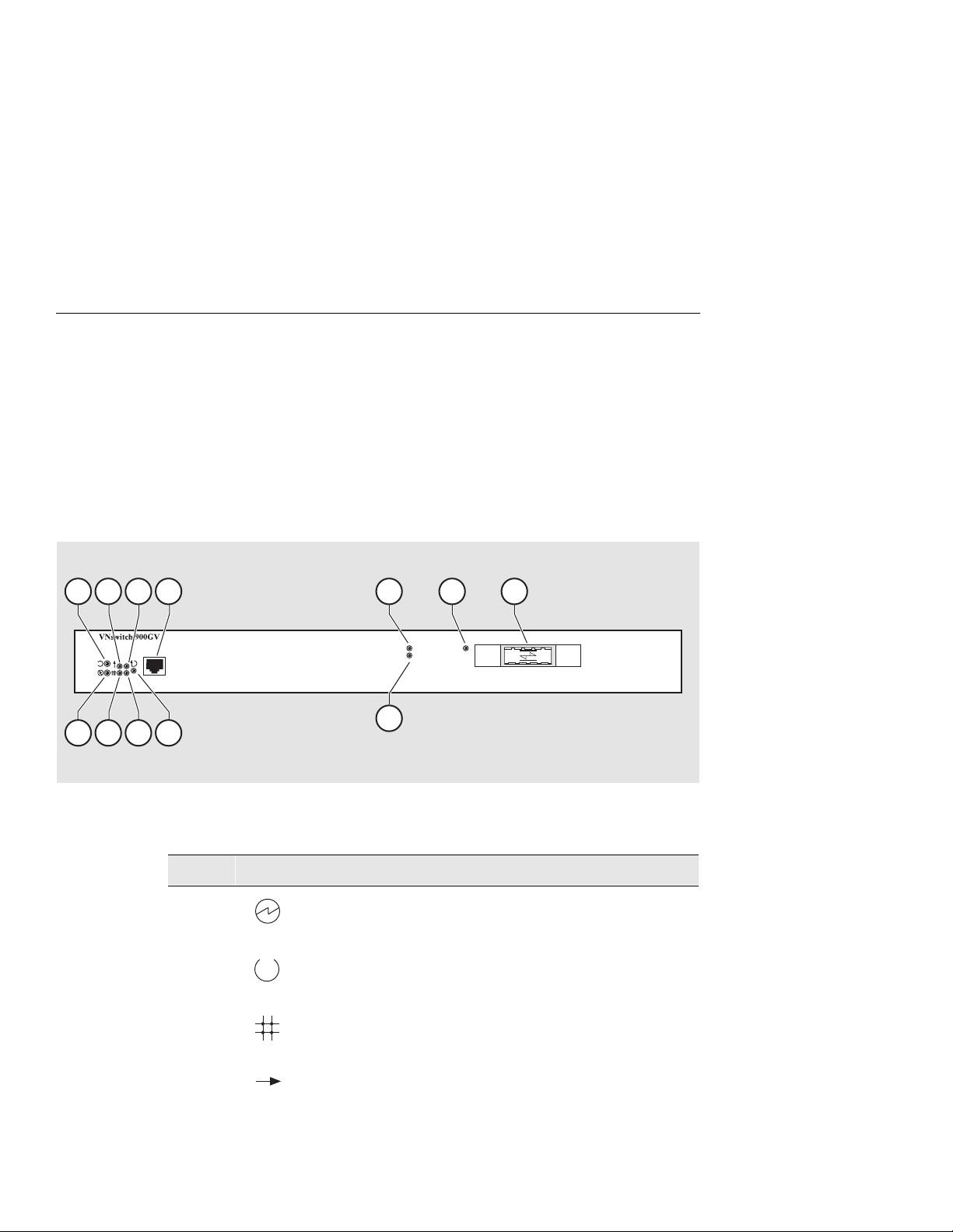
Front Panel Components
Figure 2-1 shows the front panel components and Ta ble 2- 1 describes them.
Figure 2-1: Front Panel LEDs and Connectors
7
6
4
2 9
10
8
5
3
1
Tab le 2- 1: Front Panel LEDs and Connectors
Item Icon Name Description
1 Power LED Lights when the module has power.
2 Module OK
LED
3 VNbus Stat us
LED
1211
NPB-1070-98F
Lights when the module passes self-test.
Shows if the module i s prope rly at tach ed
to a VNbus backplane.
1
4 VNbus
2-2 Installing the DIGITAL VNswitch 900GV
Activity LED
Indica te s ne twork traffi c.
(continued on next page)
1
Page 23

Item Icon Name Description
Module Components
5 Load/Dump/
Management(LDM)
Indicates the link status of the Load/
Dump/Management port.
Port Status LED
6 LDM Activity LED Indicates when the LDM port is
transmitting or receiving packets.
7 LDM Port Dedicated 10BaseT Ethernet port.
Supports upline dump. (A dump entry
must be set up in config_acct in order
for th e du mp to occur.) Th is port is
wired as a straight-through connector.
8 Reset/Dump But ton Used to either reset the module or
perform an upline dump, followed by
a reset. (A dump entry must be set up
in config_acct in order for t he dump to
occur.) If this button is pressed as
operational code initializes, the
modu l e w il l r es e t to current settings.
If the module is in operation mode,
hold the button for five sec onds. Use a
non-conductive device to press the
button.
9 Port Activity LED Indicates network traffic level.
10 Port Status LED Shows the status of the port s. Indicates
if the port is enabled or dis abled and
receiving a valid link.
11 FRU LED Indicates the GBIC is a Field
Replacable Un it (FR U ) .
12 MMI port for
Gigabit Ethernet
connectors
Support for Gigabit Ethernet MultiMode Fiber (MMF), Gigabit Eth ernet
Single-Mode Fiber (SMF). The GBIC
connecto rs are color coded : black f o r
shortwave and blue for longwave.
1
The VNbus Status and Traf fic LEDs display different indications during a loa d s tate. Refer to the release
notes for current descriptions.
Installing the DIGITAL VNswitch 900GV 2-3
Page 24

Module Components
Back Panel Components
Figure 2-2 shows the front panel components and Ta ble 2- 2 describes them.
Figure 2-2: Back Panel Components
7
6
5
234
1
NPB-9723-95F
Tab le 2- 2: Back Panel Components
Item Name Description
1 Locking tab Locks the module into a MultiSwitch 900
backplane. Con tains the hot-swap switch lever.
2 48-pin connector Provides network and power connections to the
module when the module is installed in a
MultiSwitch 900 .
3 Grounding bolt Provides a chassis grounding connection
between the module an d the MultiSwitch 900.
4 Manufacturing label Lists the module’s part number, serial number,
revision level, and power requirements.
5 160-pin connector Provides network and power connections to the
module when the module is installed into a
MultiSwitch 900 .
6 Mounting tab Secures the module when it is installed into a
MultiSwitch 900 .
7 Grounding fingers Provide additional chassis g rounding between
the module and a MultiSwitch 900.
2-4 Installing the DIGITAL VNswitch 900GV
Page 25

How to Install the Module
The hot-swap fea ture al lows yo u to i nstall t he modul e into t he DIGI TAL Mult iSwit ch
900 without turn ing off power. Seating the modu le initiates the power-up.
To install the module, complete the following tasks.
Task 1: Compare the Power Ratings
Compare your module’s p ower requirements (1) with the value s sho wn in the Chassi s
Manager (2) status displ ay (Figure 2-3).
If any of the module’s power requirements exceed the values shown in the status
display, add another power supply (see the DIGITAL MultiSwitch 900 Owner’s
Manual).
Figure 2-3: Sample Power Ratings
How to Install the Module
1
41.0W
6.70 A
0.12 A
0.50 A
5 V
12 V
15 V
Available: 90.5 W
5V: 13.0 A, 15V: 3.5 A
2
NPB-1048-98F
Installing the DIGITAL VNswitch 900GV 2-5
Page 26

How to Install the Module
Task 2: Seat the Module
To seat the module int o a DIGITAL MultiSwitch 900 (Figure 2-4), complete the
following steps:
Step Action
1 Place the module’ s mounting tab (1) into a mounting slot on the
DIGITAL MultiSwitch 900.
2 Pu l l u p th e re lease leve r (2) to its unlocked position.
3 Pivot the module on the mounting tab, align the connectors, and firmly
push the module onto the back plane connectors.
4 Pr e s s do w n th e r el e a s e le v er (3) to ensure that it is locked.
Figure 2-4: Seating the Module
2
4
3
1
NPB-0004-95F
2-6 Installing the DIGITAL VNswitch 900GV
Page 27

Task 3: Verify Initial LED Operation
If… Then…
This is a new installation Turn on the power to the DIGITAL
How to Install the Module
MultiSwitch 900.
The module was installed while the
DIGITAL MultiSwitch 900 is
powered up
To verify initi al L ED ope ration, check the following stages:
Stage De scri ption
1 When the module receives power, the module ’s Power LED lights and
remains lit.
2 The module runs a self–test.
The initial self-test takes appr oximately thre e minutes to
Note:
complete.
3 After the module completes self-test, the Module OK LED lights and
remains lit.
4 The DIGITAL Mult iS witch 900 LCD display shows VNswitch
900GV.
Seating the module initiates the modu le’s
power–up sequence.
If the LEDs do not operate as described,
refer to Appendix A, Problem Solving.
For locations of the module’s LEDs, refer
to Figure 2-1.
Installing the DIGITAL VNswitch 900GV 2-7
Page 28

How to Install the Module
Task 4: Connect the LDM Port Cable
To perform a remote dump, the LDM cabl e mu st be connected to the LDM port. The
LDM port uses straight-through, 10Base T, 8-pin MJ connectors.
To connect th e LDM port c able t o the LDM po rt (Figur e 2-5), complete the following
steps:
Step Action
1 Align the release tab on the cable plug (1), with the keyway on the
module’s 10BaseT port connector.
2 Insert the plug into the connector , ensuring that the rele ase tab snaps into
the locked position.
Figure 2-5: LDM Port Cable Conne ct i on
t
e
rn
e
VNswitch 900GV
th
I/E
D
D
F
2
2-8 Installing the DIGITAL VNswitch 900GV
1
NPB-1051-98F
Page 29

Task 5: Connect the GBIC Connector
The DIGITAL VNswitch 900GV uses a Gigabit Interface Converter (GBIC)
connector.
To connect the GBIC connector (Figure 2-6), co mplete the following steps :
Step Action
1 Se l ect th e ap p r o pri ate GBIC as li st ed in th e section title d Task 6 :
Connect the Duplex SC Cables.
2 Align the release tab on the cable plug (1), with the keyway on the
module’s GBIC port connector.
3 Insert the plug into the connector , ensuring that the rele ase tab snaps into
the locked position.
Figure 2-6: GBIC Connection
How to Install the Module
2
VNswitch 900GV
1
NPB-1067-98F
Installing the DIGITAL VNswitch 900GV 2-9
Page 30

How to Install the Module
Task 6: Connect the Duplex SC Cables
The DIGITAL VNswitch 900GV uses both Single-Mode Fiber (SMF) and MultiMode Fiber (MMF) port connectors .
Some fiber optic equipment can emit laser or infrared light that can injure your
eyes. Never look into an opt ical fiber or connector port. Always assume t he cable
is connected to a light source.
Table 2-3 and Table 2-4 describe s upported Short Wave Length and Long Wave
Length cable distances.
Tab le 2- 3: Short Wave Length - Black (HP 5601 - 850)
Fiber Size Fiber Bandwidth Distance
62.5 Microns (MMF): 160MHz per Kilo me ter 2 to 220 Meters
200MHz per Kilometer 2 to 275 Meters
WARNING
50.0 Microns (MMF) 400MHz per Kilometer 2 to 250 Meters
Tab le 2- 4: Long Wave Length - Blue (HP 5611 - 1300)
Fiber Size Fiber Bandwidth Distance
62.5 Microns (MMF) 500MHz per Kilometer 2 to 550 Meters*
50.0 Microns (MMF) 400MHz per Kilometer 2 to 550 Meters*
10.0 Microns (SMF) 2 to 5,000 Meters
* requires of fset launch fiber jumper
MMF indicates Multi Mode Fiber
SMF indicates Single Mode Fiber
2-10 Installin g the DIGI TAL VNswitch 900GV
Page 31

Overview
Introduction
The setup por t on the DIGITAL Mult iSwit ch 900 chassi s allo ws you to ac ces s and set
DIGITAL VNswitch 900GV parameters. This chapter describes how to access the
module from the DIGITAL MultiSwitch 900 setup port and how to set those
parameters.
In This Chapter
This chapter contains the following topics:
Topic Page
Setup Port Signaling Standards 3-2
Chapter 3
Installing the Setup Port Cable
Setup Port Device Cabling 3-2
Connecting to the Setup Port 3-3
Installing the Set up Port Cable 3-1
Page 32

Setup Port Signaling Standards
Setup Port Signaling Standards
Signals from the MultiSwitch 900 Chassis Manager setup port conform to the EIA232D signal ing standard at 9600 b aud. To the user, the port appea rs as a data terminal
equipment (DTE) device.
The MultiSwitch 900 Chassi s Manager setu p port is compati ble with devic es that use
the EIA-423 signaling standard.
Setup Port Device Cabling
The setup port (Figure 3-1) on the DIGITAL MultiSwitch 900 chassis can be
connected to a setup port device (a terminal or personal computer) by using the
following cables and adapters:
If the setup port device is… Use this cable… With this adapter…
PC with a 9-pin D-sub
communications port
Terminal with a 25-pin D-sub
connector
Terminal with a 6-pin MMJ
connector
BN24H-xx
BN24H-xx
BN24H-xx1
1
1
H8571-J
H8575-A
Not required
xx indicates cable length in meters
1
For further information on available connectors pin assignments, and adapters used
with this product, refer to Appendix B.
3-2 Installing the Setup Port Cable
Page 33

Connecting to the Setup Port
To connect to the se tup port on the module, complete the followi ng steps:
Step Action
1 Ensure that the tra nsmit and re ceive baud rates on the setup port dev ice
are set to 9600 baud, 8-bits, no parity.
2 Connect the setup port device to the setup port connector on the
DIGITAL MultiSwitch 900.
The following le gend identifies the setup port cabling in Figure 3-1:
Item Description
1 Out-of-Band Management (OBM) Port
2 Setup Port
3 Setup Port Cable
Connecting to the Setup Port
4 Setup Port Device
Installing the Set up Port Cable 3-3
Page 34

Connecting to the Setup Port
Figure 3-1: Setup Port Cabling Components
DIGITAL MultiSwitch 900
1
2
DIGITAL MultiSwitch 900
3
BN24H
After all cables are connected, go to Chapter 4.
3-4 Installing the Setup Port Cable
4
H8571-J
H8575-A
Page 35

Configuring the Module in a DIGITAL
Overview
Introduction
This chapter describes how to configure your DIGITAL VNswitch 900GV module
when it is installed in a DIGITAL MultiSwitch 900 chassis.
In This Chapter
This chapter contains the following topics:
Topic Page
Assigning an IP Address 4-2
Chapter 4
MultiSwitch 900
DIGITAL MultiSwitch 900 INSTALLATION MENU 4-3
[9] Start Redirect Mode 4-4
Using Menus to Configure the Module 4-5
[1] Restart with Factory Defaults 4-6
[2] Restart with Current Settings 4-7
[3 ] Sh o w Cu rrent Settings 4-8
[4] Configure IP 4-9
[5] Go to Local Console 4-17
[6] Product-Specific Options (VNswitch 900GV) 4-18
[10] Product-Specific Options (MultiSwitch 900) 4-19
Configuring the Module in a DIGITAL Mul ti Switch 900 4-1
Page 36

Assigning an IP Address
Assigning an IP Address
After install ing the modu le in a DIGITAL Mult iSwitch 9 00 chassis an d connecting th e
cables, you need to assign an IP address. Do this usi ng the command line interf ace,
which is accessed through a terminal connec ted to the setup port on the MultiSwitch
900 chassis.
The VNbus does not connect to the backplane by default. The VNbus is
configured using the clearVISN M u lt iChassis Manag er .
To perform a Telnet session, you must assign an IP address. To do this, complete the
following steps:
Step Action
1 Install the module into a slot on the DIGITAL MultiSwitch 900.
2 Redirect the DIGITAL MultiSwitch 900 Chassis Manager setup port to
the DIGITAL VNswitch 900GV slot.
NOTE
3 Select the IP Configuration option from the menu.
4 Set the in-band IP address.
5 Set the default gateway, if necessary.
6 Return to the VNswitch 900GV INSTALLATION MENU and select
[2] Restart with Current Settings.
7 Open a Telnet s essio n int o the modu le from the m anageme nt stati on for
further config uration . The syst em dis plays copyr ight st atem ents a nd the
following prompt:
MOS Operator Control
Main>
After the system prompt (Main>) appears, refer to the DIGITAL
VNswitch 900 Series Switch Management for further configuration
information.
4-2 Configuring the Modul e in a DIGITAL MultiSwitch 900
Page 37

DIGITAL MultiSwitch 900 INSTALLATION MENU
DIGITAL MultiSwitch 900 INSTALLATION MENU
The following example shows the DIGITAL MultiSwitch 900
INSTALLATION MENU.
To access the module’s setup screen, you must choose option [9] Start
Redirect Mode.
DIGITAL MultiSwitch 900
====================================================
DIGITAL MultiSwitch 900 INSTALLATION MENU
[1] Restart with Factory Defaults
[2] Restart with Current Settings
[3] Show Current Settings
[4] Configure IP
[5] Dump Error Log
[6] Downline Upgrade
[7] Configure Out-of-Band Port
[8] Start Event Display Mode
[9] Start Redirect Mode
[10] Product-Specific Options
...
...
...
===========================================================
Enter selection number: 9 <Return>
Press Return for Main Menu ...
Configuring the Module in a DIGITAL MultiSwitch 900 4-3
Page 38

[9] Start Redirect Mode
[9] Start Redirect Mode
The Start Redirect Mode option redirects the DIGIT AL MultiSwitch 900
Chassis Manager setup port to the setup port of any network module (such as the
DIGITAL VNswitch 900GV) that is installed into the MultiSwitch 900. This option
allows you to configure or obtain status of an installed network module by accessing
the specified network module’s installation menu.
After you choose the Start Redirect Mode option from the DIGITAL
MultiSwitch 900 INSTALLATION MENU, the screen prompts you for a slot
number, as shown in the following example. After you ent er the number of t he s lot in
which the DIGITAL VNswitch 900GV is in st alled, the console is redirected to this
slot.
The slot number may change to reflect the slot number in which your module is
installed.
The following example shows you how to redirect the console to a specific slot:
NOTE
Enter the slot number for redirection (1-8): 3 <Return>
Console redirected to 3: VNswitch 900GV
Attempting connection [Ctrl/C to Abort]...
If the redirection is successful, after y o u press Return, the VNswitch 900GV
INSTALLATION MENU appears on your screen. If redirection is not successful, for
example, you ent ere d a number for an empty slot, you can press Return to start again
at the DIGITAL MultiSwitch 900 INSTALLATION MENU.
4-4 Configuring the Modul e in a DIGITAL MultiSwitch 900
Page 39

Using Menus to Configure the Module
Using Menus to Configure the Module
The following screen s hows the options available from the VNswitch 900GV
INSTALLATION MENU when the module is oper ating in a MultiSwitch 900
configuratio n. Depend ing on the confi guratio n stat e of the module , som e option s may
not appear.
Note that whe n your modul e is inst alled in the MultiSwi tch 900 , the slot number where
the module is ins talled appears at the top of the menu.
VNswitch 900GV
===========================================================
[1] Restart with Factory Defaults
[2] Restart with Current Settings
[3] Show Current Settings
[4] Configure IP
[5] Go to Local Console
[6] Product-Specific Options...
[Ctrl/C] Return to Chassis Manager Installation Menu
===========================================================
Enter selection: n <Return>
- slot 3
VNswitch 900GV INSTALLATION MENU
Configuring the Module in a DIGITAL MultiSwitch 900 4-5
Page 40

[1] Restart with Factory Defaults
[1] Restart with Factory Defaults
This option reboots the module, causing its configured Nonvolatile Random Access
Memory (NVRAM) parameters to b e initialized to factory default values followed by
a module reset. Allow a pproximately three min utes for the module to reboot and
complete self-test. To reset the module without losing the settings, use option [2]
Restart with Current Settings.
CAUTION
This action de letes all conf igured settings and replaces them with factory default
values. All configuration settings will be lost.
The following example shows the dialog associated with this option:
VNswitch 900GV
==========================================================
- slot 3
RESTART WITH FACTORY DEFAULTS
* * * * * * * * * * * * * * * * * * * * * * * * * *
* * * *
IMPORTANT! IMPORTANT! IMPORTANT!
* * * * * * * * * * * * * * * * * * * * * * * * * * * * * *
This selection will delete the current configuration
settings and reset the system with the factory default
settings. All configuration settings will be lost.
* * * * * * * * * * * * * * * * * * * * * * * * * * * * * *
==========================================================
Press Y to confirm [N]: <Return>
Press Return for Main Menu...
4-6 Configuring the Modul e in a DIGITAL MultiSwitch 900
Page 41

[2] Restart with Current Settings
This option resets the module but leave s the module’s configured nonvolatile
configuration storage parameters at their current values.
Because this option restarts only the module, and leaves storage parameters
configured at their current values, the module’s restart process takes only 1
minute.
The following example shows the dialog associated with this option:
[2] Restart with Current Settings
NOTE
VNswitch 900GV
=============================================================
RESTART WITH CURRENT SETTINGS
This selection will reset your system with the current
configuration settings.
=============================================================
Press Y to confirm [N] : <Return>
Press Return for Main Menu...
- slot 3
Configuring the Module in a DIGITAL MultiSwitch 900 4-7
Page 42

[3] Show Current Settings
[3] Show Current Settings
This opt ion shows the module’s cur r ent settings. If the module is being configured for
the first time, some fields will be blank. The read /write community name is case
sensitive.
The following example shows the display associated with this option:
VNswitch 900GV
===================================================================
VNswitch 900GV, 1 GigabitEth, DME Pass 4, HW=,RO=x,#525, SW=V2.2
SysUpTime : 6 days 00:03:18 2 resets
SNMP Read/Write Community : public
SNMP Trap Addresses : None Configured
Deafult Gateway: : Not configured
Interface IP Address Subnet Mask Other Info
In-Band 16.20.216.91 255.255.255.0 08-00-2B-A6-0E-05
OBM Port 16.20.66.156 255.255.255.0 Speed 9600 bps
====================================================================
Press Return for Main Menu...
- slot 3
4-8 Configuring the Modul e in a DIGITAL MultiSwitch 900
Page 43

[4] Configure IP
This option prov ides you with IP configuration selections.
For any of the IP Configuration menu options to take effect, the modu le needs to
be reset. Use [2] Restart with Current Settings from the
VNswitch 900GV INSTALLATION MENU. Allow approximately 1 minute
for the module to res tart a nd complete self -te st. (Becaus e this option re star ts only
the module, and leaves storage parameters conf igured at their current values, the
module’s restart process takes only 1 min ute.)
The following example shows the dialog associated with this option:
VNswitch 900GV - slot 3
=========================================================
=========================================================
[4] Configure IP
NOTE
* * * * * * * * * * * * * * * * * * * * * * * * * * *
* Configuration will not take effect until module is *
* restarted. *
* * * * * * * * * * * * * * * * * * * * * * * * * * *
[1] Set SNMP Read/Write Community
[2] Add SNMP Trap Address
[3] Delete SNMP Trap Address
[4] Set In-Band Interface IP Address
[5] Set Out-of-Band Interface IP Address
[6] Set Default Gateway
[7] Return to Main Menu
Enter selection number : n
IP CONFIGURATION
<Return>
The following pages describe the IP Configuration options:
Topic Page
[1] Set SNMP Read/Write Community 4-11
[2] Add SNMP Trap Addresses 4-12
Configuring the Module in a DIGITAL MultiSwitch 900 4-9
Page 44

[4] Configure IP
Topic Page
[3] Delete SNMP Trap Addresses 4-13
[4] Set In-Band Interface IP Address 4-14
[5] Set Out-of-Band Interface IP Address 4-15
[6] Set Default Gateway 4-16
4-10 Configuring the Module in a DIGITAL MultiSwitch 900
Page 45

[1] Set SNMP Read/Write Community
This option prompts you to enter the module’s read /write community name. Th e
community name can be used for read/write access control. The read/write community
name is case sensitive. The default is public.
The following example shows the dialog associated with this option:
[4] Configure IP
VNswitch 900GV
================================================================
SET SMNP READ/WRITE COMMUNITY
Format: The format for a community name is a string,
consisting of 4 to 31 printable ASCII characters, that
describes the relationship between an SNMP agent and
one or more SNMP managers. The string defines the
authentication mechanism that is employed to validate
the use of the community by the sending SNMP entity.
================================================================
Enter the community string [public] : <Return>
Press Return for IP Configuration Menu...
- slot 3
Configuring the Module in a DIGITAL MultiSwitch 900 4-11
Page 46

[4] Configure IP
[2] Add SNMP Trap Addresses
This option prompts you to enter IP addresses to which the DIGITAL VNSwitch
900GV module se nds SNMP traps. You can ente r up to eight trap addres s es. If one or
more SNMP trap addresses were previously configured, the screen displays those
addresses.
The format of an SNMP trap address is the standard 4-octet dotted decimal notation
for an IP address, where each octet of the address is represented as a decimal value,
separated by a decimal point (.), for example, 16.20.54.156.
The following example shows the dialog associated with this option:
Enter selection : 2
VNswitch 900GV - slot 3
=================================================================
ADD SNMP TRAP ADDRESSES
Format: The standard 4 octet dotted decimal notation in
which each octet of the address is represented as a
decimal value, separated by a ’.’ character.
example: 16.20.54.156
=================================================================
Configured SNMP Trap Addresses: 16.20.216.81
1
Enter a Trap address [ ]: 16.20.216.89 <Return>
Trap address added! Enter a Trap Address [ ] : <Return>
Press Return for IP Configuration Menu...
Line Field Description
Configure SNMP T rap
1
Addresses:
This line appears only if the module has been
previously co nfigured.
16.20.216.81
Trap address [ ] :
2
16.20.216.89
Enter the trap address that you have chosen,
then press the Return key.
<Return>
4-12 Configuring the Module in a DIGITAL MultiSwitch 900
2
Page 47

[3] Delete SNMP Trap Addresses
This option prompts you to select SNMP trap addre sses for deletion from the
community trap address table. If one or more SNMP trap addresses were pre viously
configured, the screen displays those trap addresses.
The following example shows the dialog associated with this option:
[4] Configure IP
VNswitch 900GV - slot 3
================================================================
Format: The standard 4 octet dotted decimal notation in which each
octet of the address is represented as a decimal value, separated
by a ’.’ character.
=================================================================
Configured SNMP Trap Addresses : 16.20.216.81
Trap address [ ] : 16.20.216.81 <Return>
Trap address deleted. Enter a Trap Address [ ] : <Return>
Press Return for IP Configuration Menu...
Enter selection : 3
DELETE SNMP TRAP ADDRESSES
example: 16.20.40.156
Line Field Description
Configure SNMP T rap
1
Addresses:
This line appears only if the module has been
previously co nfigured.
16.20.216.81
Trap address [ ] :
2
16.20.216.81
Enter the trap address that you have chosen,
then press the Return key.
<Return>
1
2
Configuring the Module in a DIGITAL MultiSwitch 900 4-13
Page 48

[4] Configure IP
[4] Set In-Band Interface IP Address
This option prompts you to change or enter the module ’s in-band IP address, subnet
mask, and default gateway for the in-band interf ac e. If an IP address was previously
configured, the scre en dis play s an i n-band I P add ress. The fa ctory d efault set ting i s no
in-band address.
You do not need to configure the module with a subnet mask for SNMP
communications with management stations located on the same subnet as the module.
The following example shows the dialog associated with this option:
VNswitch 900GV
================================================================
Format: The standard 4 octet dotted decimal notation in which
.
To delete the IP address, enter 0 in the appropriate address
field.
Interface
In-Band 16.20.216.91 255.255.255.0 08-00-2B-A3-CD-08
OBM Port 16.20.66.156 255.255.255.0 Speed 9600 bps
================================================================
Enter the IP address [16.20.126.24] : 16.20.54.156 <Return>
Enter the Subnet Mask [255.0.0.0] : 255.255.0 0 : <Return>
each
value, separated
example: 16.20.40.156
IP Address Subnet Mask Other Info
- slot 3
IN-BAND INTERFACE IP ADDRESS CONFIGURATION
octet of the address is represented as a decimal
by a ’.’ character.
Press Return for IP Configuration Menu.....
NOTE
If Routing is enabled, you wil l be asked to supply an IFC number prior to entering an
IP address.
4-14 Configuring the Module in a DIGITAL MultiSwitch 900
Page 49

[5] Set Out-of-Band Interface IP Address
This opti on prompt s you t o chan ge or ente r the IP a ddre ss and subnet mask fo r th e outof-band interface. The module does not need to be configured with a subnet mask for
SNMP communicat ions when management sta tions are on the same subnet as the
module.
The format f or thes e values is the s tandard 4-oc tet do tted deci mal nota tion, wher e each
octet of the addr ess is rep rese nted as a decim al val ue, sepa rated by a dec imal point (. ).
If the module is in a MultiS witch 900, the OBM feature allows you to manage your
module through the OBM port locat ed on the MultiSwitch 900. To enabl e out-of-band
management, you need to as sign an OBM IP address.
The following example shows the dialog associated with this option:
[4] Configure IP
VNswitch 900GV
================================================================
OUT-OF-BAND INTERFACE IP ADDRESS CONFIGURATION
Format: The standard 4 octet dotted decimal notation in which
value, separated
.
To delete the address, enter 0 in the appropriate address
field.
================================================================
Interface
In-band 16.20.216.91 255.255.255.0 08-00-2B-A3-CD-08
OBM Port 16.20.66.156 255.255.255.0 Speed 9600 bps
================================================================
Enter the IP address [16.20.66.156] : 16.20.54.155 <Return>
Enter the Subnet Mask [255.255.255.0] : 255 255 192 0 <Return>
IP Address Subnet Mask Other Info
Press Return for IP Configuration Menu...
- slot 3
each
octet of the address is represented as a decimal
by a ’.’ character.
example: 16.20.40.156
Configuring the Module in a DIGITAL MultiSwitch 900 4-15
Page 50

[4] Configure IP
[6] Set Default Gateway
This option sets the default gateway, if necessary. This is the address the module uses
when communicating with a remote host. The default gateway address mu st be in the
same subnet as your in-band address.
The following example shows the dialog associated with this option:
VNswitch 900GV
===========================================================
SET IN-BAND INTERFACE DEFAULT GATEWAY ADDRESS
Format: The standard 4 octet dotted decimal notation in which
each
value, separated
example: 16.20.40.156
To delete the address, enter 0 in the appropriate
address field.
===========================================================
Default Gateway [] : 16.126.16.254 <Return>
Default Gateway Address Set.
Press Return for IP Configuration Menu . . .
- slot 3
octet of the address is represented as a decimal
by a ’.’ character.
4-16 Configuring the Module in a DIGITAL MultiSwitch 900
Page 51

[5] Go to Local Console
To perform additiona l configuration s on th e mod ule, select [5] Go To Local
Console from the VNswitch 900GV INSTALLATION MENU.
The system will dis play the copyrigh t statements and the following prompt:
MOS Operator Control
Main>
From the Main> prompt, you can perform additional configuration. Refer to the
DIGITAL VNswitch 900 Series Switch Management for furt her configuration
information.
[5] Go to Local Console
Configuring the Module in a DIGITAL MultiSwitch 900 4-17
Page 52

[6] Product-Specific Options (VNswitch 900GV)
[6] Product-Specific Options (VNswitch 900GV)
To view or clear the modu le’s error log entries , s elect [6] Product-Specific
Options from the VNswitch 900GV INSTALLATION MENU:
VNswitch 900GV
===========================================================
VNswitch 900GV Product Specific Options
[1] Clear CRASH and DIAGNOSTIC Error Logs
[2] List CRASH and DIAGNOSTIC Error Logs
[3] Return to Main Menu
===========================================================
Enter selection: n <Return>
If you select [2] List CRASH and DIAGNOSTIC Error Logs, the screen
shows the list of messages recorded to both logs. Select option [1] to cl ea r the
infor m a tion in the logs. Se le ct
option [3] to return to the VNswitch 900GV
INSTALLATION MENU.
4-18 Configuring the Module in a DIGITAL MultiSwitch 900
Page 53

[10] Product-Specific Options (MultiSwitch 900)
[10] Product-Specifi c Opti ons (Multi Switch 900)
This option provides product-specific selec tions when you are using a MultiS witch
900. When select ed , the opt ion allows you to ena ble an d disa ble the aut omati c VNbus
connection.
DIGITAL MultiSwitch 900
=======================================================
PRODUCT-SPECIFIC OPTIONS
[1] Enable/Disable Automatic VNbus Connection
[2] Return to Main Menu
Enter selection:
If you select the option [1] Enable/Disable Automatic VNbus
Connection the following menu appears:
DIGITAL MultiSwitch 900
====================================================================
ENABLE / DISABLE AUTOMATIC VNbus CONNECTION
Enabling Automatic VNbus Connection means that certain backplane
channels will be reserved for a VNbus. The channels will be reserved
reserved as soon as this feature is Enabled, and will remain
reserved until this feature is Disabled. When a VNswitch module
is inserted into the chassis, it will connect automatically to the
VNbus. The Enable function will return an error if backplane channels
cannot be reserved due to existing conditions.
Disabling Automatic VNbus Connection means that no backplane channels
will be reserved for a VNbus. Inserting VNswitch modules will not
create connections to a VNbus. If any VNswitch modules are
connected to a VNbus when the Disable mode is selected, the VNbus
will remain until the last VNswitch module is removed from the chassis.
====================================================================
Automatic VNbus connection is Enabled. Would you like to Disable it? [N]
Press Return for Product-Specific Options Menu ...
Configuring the Module in a DIGITAL MultiSwitch 900 4-19
Page 54

Page 55

Removing the Cables, Connector and
Overview
Introduction
This chapte r describes ho w to rem ove the DIGITAL VNswit ch 900GV modul e, cables
and connectors from a DIGITAL MultiSwitch 900 chass is .
In This Chapter
This chapter contains the following topics:
Topic Page
Removing the Cables 5-2
Chapter 5
Module
Removing the GBIC Card 5-3
Unseating the Module 5-4
Removing the Cables, Connector and Module 5-1
Page 56

Removing the Cables
Removing the Cables
Before the module i s unseated, the LDM cables must be removed from the module. To
remove the cable s (Figure 6-1 and Figure 5-1), complet e th e s e st ep s :
Step Action
1 Push in the release tab (1) on the side of the connector.
2 Pull out the cable(s).
Figure 5-1: Removing the LDM Port Cable
2
t
e
rn
e
VNswitch 900GV
th
I/E
D
D
F
1
5-2 Removing the Cables, Connector and Module
NPB-1052-98F
Page 57

Removing the GBIC Card
The GBIC is hot-swappable and can be removed while the DIGITAL VNswitch
900GV has power. To remove the connector ( Figure 5-2), complete these steps:
Step Ac tion
1 Push in th e r elease tab (1) on the side of the card.
2 Pull out the card.
Figure 5-2: GBIC Removal
Removing the GBIC Card
2
VNswitch 900GV
1
NPB-1067-98F
Removing the Cables, Connector and Module 5-3
Page 58

Unseating the Module
Unseating the Module
To unseat the module from the DIGITAL MultiSwitch 900 chassis (Figure 5-3),
compl ete the foll o w ing steps :
Step Action
1 Lift the release lever (1) at the to p of the DIGI TAL MultiSwit ch 900
slot.
2 While holding up the release lever (2), pivot the module back on its
bottom mounting tab.
3 Lift the module (3) from the backplane.
Figure 5-3: Unseating the Module
1
2
3
5-4 Removing the Cables, Connector and Module
NPB-0008-95F
Page 59

Overview
Introduction
This appendix de scri bes how to diagn ose an d solve problem s with the mod ule usi ng a
light-emitting diodes (LED) displa ys.
In This Appendix
This appendix con tains the following topics:
Topic Page
Appendix A
Problem Solving
Normal Power-Up A-2
LED Descriptions A-3
Problem Solving Using LEDs A-5
Problem Solving A-1
Page 60

Normal Power-Up
Normal Power-Up
When the module’s power is in itially turned on, the following events occur:
Event Description
1 The module's Power LED light s as soon as power is ap plied to the uni t.
2 The module i nitia tes it s built -in sel f-test. F lashing Port Sta te LEDs and
3 After the suc cessf ul c omp letio n of s elf- tes t (wi thin t hr ee m inute s aft er
4 The remaining LEDs now indicate their operational status.
Refer to Table A-1 for a list of LED states that are possible for each of the module.
Port Activit y LE Ds indicate that the module is running various
subroutines as part of the self-test.
power is applied), the Module OK LED becomes lit.
A-2 Problem Solving
Page 61

LED Descriptions
LED Descriptions
The module's LEDs provi de dynamic indicatio ns of the module’s stat us. The LEDs can
be in various states (on, off, or flashing), and can chan ge co lor (green or yellow)
depending on the operational status of the modu le or the level of activity on the
network.
Table A-1 shows the states that are poss i b le for ea ch of the module's LEDs.
Tab le A-1 : Module LED States
LED Off On (Green) On (Yellow) Flashing
Power LED No power or not
enough power
available in the
MultiSwitch
900.
Module OK LED Self-test has
failed or is in
progress.
VNbus Status
No connection. Module is
LED
VNbus Activity
No traffic. N/A Heavy traffic.
LED
LDM Port Status
LED
No link
established.
Module is
receiving power.
Module passed
self-test.
properly
attached to one
of the backplane
VNbuses.
Proper link
established.
N/A N/A
N/A Indicates a
downline load or
a nonfatal
failure.
See release
1
notes.
(Green)
VNbus is
disconnected by
management
software.
(Yellow) Port is
See release
1
notes.
receiving/
transmitting
traffic on the
backplane.
N/A Disabled.
1
The VNbus Status and Activity LEDs have different indications during a load st ate. Refer to the re lease notes for current
descriptions.
(continued on next page)
Problem Solving A-3
Page 62

LED Descriptions
LED Name Off On (Green) On (Yellow) Flashing
LDM Act ivity
LED
N/A Indicates high
traffic.
N/A Transmitting or
receiving
packets.
Port Status LEDs No valid li nk
being received
on the port.
No cable is
attached.
Port is broken.
Port Activity
LEDs
No traffic is
being received/
transmitted to
the port.
Port is enabled
onto the front
panel and is
receiving a va lid
link.
Port is enabled
onto the front
panel and is
receiving a va lid
link.
Port failure. (Green)
Port is
management
disabled for
forwarding but
is still rec eiving
a valid link.
N/A (Green)
Port is receiving/
transmitting
traffic on the
front panel.
A-4 Problem Solving
Page 63

Problem Solving Using LEDs
When diagnosing a problem with the module , note that the problem is often indicated
by the combined states of the module LEDs. Tab le A-2 lists the typ ical combi n ed
states of the LEDs for various error condit ions that can occur during initial inst allatio n
of the device, along with probable causes and corrective actions to take.
If any of the following problems persist after taking corrective action, either
replace the module or contact your DIGITAL service representative.
Tab le A-2 : Problem Sol vi ng U si ng the LEDs
Symptom Probable Cause Corrective Action
Problem Solving Using LEDs
NOTE
Power LED
is off.
Module OK
LED is off.
Module OK
LED is
flashing, but
module
continues to
operate
normally.
The module is not
receiving +5 Vdc.
Self-t est failed. If the LED does not light within 3
A nonfatal error
occurred.
Check the power stat us on the Chassi s
Manager status display.
If the Chassis Manager status display
indicates that po w er is av ailable for
this module, press the release lever and
reseat or remove the module.
Inspect the module’s 48- or 160-pin
connector for bent or broken pins. If
any are bent or broken, replace the
module.
minutes, lift and reseat the release
lever m o mentarily to repeat the self test.
Contact your DIGITAL service
representative.
(continued on next page)
Problem Solving A-5
Page 64

Problem Solving Using LEDs
Symptom Probable Cause Corrective Action
VNbus Status
LED is off.
VNbus
Activity L ED
is off.
LDM Port
Status LED is
off.
No connection. Check that the module is properly
attached to one of t h e b ackplane
VNbus channels and that the VNbus
is co nn ected by m anagement
software.
Ther e is low traffic
activity or no traffic
activity.
Ensure that there is traffic activity. If
the VNbus Activity LED fai ls to turn
on, then turn the module off
momentarily b y removing it from the
power supply. Chec k t hat th e VNbus
Activity LED blinks momentarily
during the LED power–up self –test.
The m odule or a n y
other unit in the
MultiSwitch 900 may
Connect a known active VNbus
channel to any unit in the
MultiSwitch 900.
not be connected to an
active VNbus channe l.
If the module is
Replace the module.
connected to an active
VNbus and the VNbus
Activity LED is off, the
module is defective.
No link established. Check that a proper link has been
established.
A-6 Problem Solving
Port Status
LEDs are off.
Port Activity
LEDs are off.
No cable attached or
port is broken.
There is low or no port
activity.
Ensure that the cable
has activity on it. If the
LED still fails to tur n
on, the module is
defective.
Check cable type.
Ensure that the port is present. If the
Port Activity L ED stills fails to turn
on, then turn the module off
momentarily b y removing it from the
power supply. Check that the Port
Activity LEDs blink momentarily
during the LED power-up self-te st.
Replace the module.
Page 65

Appendix B
Connector Pin Assignments and Adapters
Overview
This appendix shows detai led i llu stration s of the c onnect ors an d their pin assign ments
(if applicable), and adapters used on the DIGITAL VNswitch 900GV module.
In This Appendix
This appendix con tains the following topics:
Topic Page
Connectors and Pin Assignments B-2
Adapters B-3
Connector Pin Assignment s and Adapters B-1
Page 66

Connectors and Pin Assignments
Connectors and Pin Assignments
10BaseT Port (8-pin MJ) Straight-through Connector
The DIGITAL VNswitch 900GV uses a straight -through connector for its LDM
10BaseT front panel port. Figure B-1 shows the 8-pin MJ straight-through port
connector and its pin assignments.
Figure B-1: 8- pi n MJ Straight-through Connect or
81
Table B-1 lists the pin assignments for the 8-pin MJ straight-through connector.
Table B-1: 8- pi n MJ Straight-through Connect or Pin Assignme nt s
NPB-8719-95F
Pin Assignment Pin Assi gnment
1 TX+ 5 NC
2 TX- 6 RX3 RX+ 7 NC
4 NC 8 NC
B-2 Connector Pin Assignm ents and Adapters
Page 67

Adapters
H8571-J Adapter
Figure B-2 shows the H8571-J adapter (6-pin MMJ connector to 9-pin D-sub
connector) and its pin assignments.
Figure B-2: H8571-J Adapter
6 MMJ
1
2
3
4
5
6
H8571-J
9 D-Sub(F)
1
2
3
4
5
6
7
8
9
NPB-5342-95F
Adapters
DCD
SD
RD
DTR
GND
DSR
RTS
CTS
RI
Connector Pin Assi gnments and Adapters B-3
Page 68

Adapters
H8575-A Adapter
Figure B-3 shows the H8575-A adapter (6-pin MMJ connector to 25-pin D-sub
connector) and its pin assignments.
Figure B-3: H8575-A Adapter
25 D-Sub(F)
DTR
TX+
TXRXRX+
DRS
6 MMJ
1
2
3
4
5
6
1
2
3
4
5
6
7
8
20
H8575-A
NPB-8793-95F
B-4 Connector Pin Assignm ents and Adapters
Page 69

Overview
This appendix lists the product and acous tical specifications for the DIGITAL
VNswitch 900GV module. It also provides a list of connectors on the DIGITAL
VNswitch 900GV module, the MultiSwitch 900 chassis.
In This Appendix
This appendix con tains the following topics:
Topic Page
Product Specifications C-2
Appendix C
Product Specifications
Acoustical Specifications C-3
Connectors C-4
Product Specificat ions C-1
Page 70

Product Specifications
Product Specifications
Table C-1 lists the product specific ations for the module.
Table C-1: P roduct Specifications
Parameter Specification
Environment
1
Operat i ng temperatu re
Relative Humidity 10% to 95% noncondensing
Altitude
• Operating
• Nonoperating
Power 41 W, total power
5°C to 50°C (41°F to 122°F)
Sea level to 4267 m (14,000 ft.)
Sea level to 12192 m (40,000 ft.)
6.7 A, 5 Vdc
0.12 A, 12 Vdc
0.5 A, 15 Vdc
Physical
Height 44.45 cm (17.5 in)
Width 4.45 cm (1.75 in)
Depth 15.25 cm (6 in)
Weight 1.57 kg (3.46 lb)
Shock (Class A/B for
10 G / 10 ms half sine pulse in thr ee orthogonal axes
products weighing
under 100 lbs)
Vibration (Class C) 5 to 200 Hz sine sweep @ 0.25 G limited by 0.5mm (0.02 in)
displacement DA* 200 to 500 Hz sine sweep @ 0.10 G
Certification CE, CSA, FCC, TÜV, UL, VCCI, C-TICK
1
For sites above 2400 m (8,000 f t), decrease the operating temperature specificati on by 1.8°C fo r ea ch 1000 m or 3.2°F f or
.
each 3200 ft
C-2 Product Specific ations
Page 71

Acoustical Specificat ions
Table C-2 lists the acoust ica l spe ci fic at ions for the m odu le in Engl ish. Table C-3 lists
the acoustical specificati ons for the module in German.
Tab le C-2 : Acoustical Specifications
Declared Values per IS O 9296 and ISO 7779
Acoustical Specifications
1
Product Sound
Power Level
L
, B
WAd
Sound Pressure Level
L
, dBA (bystander
pAm
positions)
Idle/Operate Idle/Operate
DIGITAL VNswitch 900GV
5.0 37
DVNGV
1
Current values for specific configurations are available from Cabletron Systems representatives. 1 B = 10
dBA.
Tab le C-3 : German Acoustical Specifications
Schallemissionswerte Werteangaben nach ISO 9296 und ISO 7779/DIN
EN27779
Produkt Schalleistung-
2
Schalldruckpegel
spegel L
WAd
, B
, dBA (Zuschauer-
L
pAm
positionen)
Leerlauf/Betrieb Leerlauf/Betrieb
DIGITAL VNswitch 900GV
5,0 37
DVNGV
2
Aktuelle Werte für spezielle Ausrüstungsstufen sind über die Cabletron Systems Vertretungen erhältlich.
1 B = 10 dBA.
Product Specifications C-3
Page 72

Connectors
Connectors
Table C-4 provides a list of connectors for DIGITAL VNswitch 900GV module and
the MultiSwitch 900 chassis.
Table C-4: Connectors
Connectors Quantity
DIGITAL VNswitch 900GV:
8-pin MJ (10BaseT twisted pair) 1
duplex Giga-Bit Interface Converter (GBIC) 1
DIGITAL MultiSwitch 900:
8-pin MJ (setup Port) 1
DB-9 (OBM) 1
C-4 Product Specific ations
 Loading...