

Page 1
UNIMUX
TM
Series
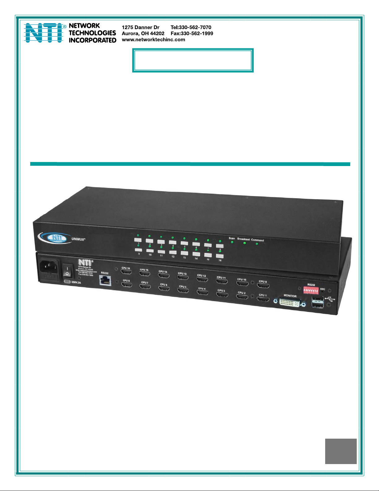
UNIMUX-DVI(A)-xHD
USB DVI KVM Switch
Installation and Operation Manual
MAN005 Rev Date 1/17/2013
Page 2

TRADEMARK
UNIMUX is a trademark of Network Technologies Inc in the U.S. and other countries
COPYRIGHT
Copyright © 2000, 2013 by Network Technologies Inc. All rights reserved. No part of this publication may be reproduced, stored
in a retrieval system, or transmitted, in any form or by any means, electronic, mechanical, photocopying, recording, or otherwise,
without the prior written consent of Network Technologies Inc, 1275 Danner Drive, Aurora, Ohio 44202.
CHANGES
The material in this guide is for information only and is subject to change without notice. Network Technologies Inc reserves the
right to make changes in the product design without reservation and without notification to its users.
CE Statement
We, Network Technologies Inc, declare under our sole responsibility that the UNIMUX-DVI(A)-4/8/16/32 is in conformity with
European Standard EN55022.
Typographic Conventions
Typeface meaning Font Configuration Example
On-screen computer output Courier New-(not bold)
What you type on the computer Courier New-bold
.
C:>
C:>edit text.bat
<L> (press the “L” key)
i
Page 3

TABLE OF CONTENTS
INTRODUCTION.............................................................................................................................................................1
MATERIALS....................................................................................................................................................................2
DEFINITIONS..................................................................................................................................................................3
FEATURES AND FUNCTIONS.......................................................................................................................................4
RACKMOUNTING INSTRUCTIONS...............................................................................................................................5
To Mount in a Rack......................................................................................................................................................5
INSTALLATION...............................................................................................................................................................6
RS232 Connection.......................................................................................................................................................8
Power-Up Sequence....................................................................................................................................................9
Limitations....................................................................................................................................................................9
USING THE UNIMUX DVI KVM SWITCH ....................................................................................................................10
Front Panel Control....................................................................................................................................................10
Keyboard Control.......................................................................................................................................................10
Command Mode........................................................................................................................................................10
Scan Mode..............................................................................................................................................................11
Broadcast Mode......................................................................................................................................................11
Normal Mode ..........................................................................................................................................................11
No Sun Sleep Mode................................................................................................................................................11
Select Country Code...............................................................................................................................................12
Mice and Trackballs with MACs..............................................................................................................................12
RS232 CONTROL.........................................................................................................................................................13
RS232 Connections and Configuration.....................................................................................................................13
Remote Connection................................................................................................................................................13
Baud Rate...............................................................................................................................................................13
Unit Address and Loop Back..................................................................................................................................13
Command Protocol.................................................................................................................................................15
NTI Switch Control Program For Windows 9X, NT, 2000, XP, Vista, and 7 .............................................................16
SerTest- RS232 Interface Test Program...................................................................................................................16
Main Options...........................................................................................................................................................16
KEYBOARD FEATURES..............................................................................................................................................18
Keyboard-To-Computer Translation..........................................................................................................................18
Translation Capabilities ..........................................................................................................................................18
Translation Tables ..................................................................................................................................................18
International Sun Keyboards.....................................................................................................................................19
DDC...............................................................................................................................................................................20
AUDIO SUPPORT.........................................................................................................................................................20
TROUBLESHOOTING..................................................................................................................................................21
INDEX............................................................................................................................................................................22
WARRANTY INFORMATION........................................................................................................................................22
TABLE OF FIGURES
Figure 1- Secure rackmount ears to switch.....................................................................................................................5
Figure 2- Secure switch to a rack....................................................................................................................................5
Figure 3- Connect a DVI monitor ....................................................................................................................................6
Figure 4- Connect the device(s)......................................................................................................................................6
Figure 5- Connect each CPU..........................................................................................................................................7
Figure 6- Connect the power cord...................................................................................................................................7
Figure 7- Connect RS232 control terminal......................................................................................................................8
Figure 8- Compatible device combinations.....................................................................................................................9
Figure 9- Country Codes for international SUN keyboards...........................................................................................12
Figure 10- RS232 DIP switches....................................................................................................................................13
Figure 11- RS232 connection with Matrix-Y-1 cable.....................................................................................................14
Figure 12- Pinout of Matrix-Y-1 cable ...........................................................................................................................14
Figure 13- RS232 Communication Illustrated...............................................................................................................15
Figure 14- Keyboard Layouts........................................................................................................................................19
Figure 15-DDC Button Location....................................................................................................................................20
ii
Page 4

Figure 16- Rear View of UNIMUX-DVIA-8HD...............................................................................................................20
iii
Page 5

NTI UNIMUX SERIES USB KVM SWITCH
INTRODUCTION
The UNIMUX-DVI-xHD 4,8,16 or 32-Port USB DVI KVM switch (UNIMUX) allows access to up to thirty two (32) Windows, MAC,
or SUN USB CPUs from one USB keyboard and mouse and a DVI video-enabled monitor. Internal microprocessor circuitry
allows all USB CPUs to be booted simultaneously without keyboard error. Port selection is accomplished by front panel push
buttons or commands typed on the keyboard. Port lights and status LEDs continuously update on the front panel.
Option: Audio support to enable user to connect stereo speakers to receive audio signals from connected CPUs- add "-A" to the
part number (i.e. model UNIMUX-DVIA-4HD)
Types of User Input Devices Supported:
• USB keyboard with Windows layout
• USB keyboard with SUN layout
• USB keyboard with MAC layout
• USB Mouse - (up to 3 buttons)
• USB IntelliMouse (scrollwheel)
• USB Hub
• Mouse-Trak trackball
• Logitech, Kensington and Microsoft Wheelmouse or Trackball on Mac CPUs with spec ial drivers
• Logitech Cordless Elite Duo keyboard and mouse
• Logitech wireless (S510, EX110, diNovo, LX710,MX5000)
• Crystal Vision keyboard with touchpad
• Gyration keyboard/mouse (Go 2.4)
• NTI USB-PS/2-R Adapter
• NTI USB-SUN-R Adapter
• Kensington wireless (64379)
• MS Wireless Optical Desktop (3000 and 4000)
• HP P2360AA
• Fellowes wireless keyboard (KBR0108) with mouse (MSR0238T)
• Creative Desktop Wireless 8000
• DVI monitors
• Apple USB 2.0 Keyboard (MB110LL/A)
• Apple USB 2.0 Mouse (MB112LL/A)
Types of CPUs Supported:
Any USB CPU supporting USB version 1.0 or above including:
• USB WINxx
• USB MAC
• USB SUN
• USB Linux
• USB Unix
• USB Free BSD
1
Page 6
NTI UNIMUX SERIES USB KVM SWITCH
MATERIALS
Materials supplied with this kit:
• NTI UNIMUX-DVI-xHD (4,8,16 or 32 ports) USB DVI Video KVM Switch
• Line cord, country specific
• Rack mount kit
• CD with pdf file of this manual
• 1- DB9 Female-to-RJ45 Female adapter
• 1- DB25 Female-to-RJ45 Female adapter
• 1- 5 foot RJ45-to-RJ45 CAT5 patch cable
Materials Not supplied but REQUIRED:
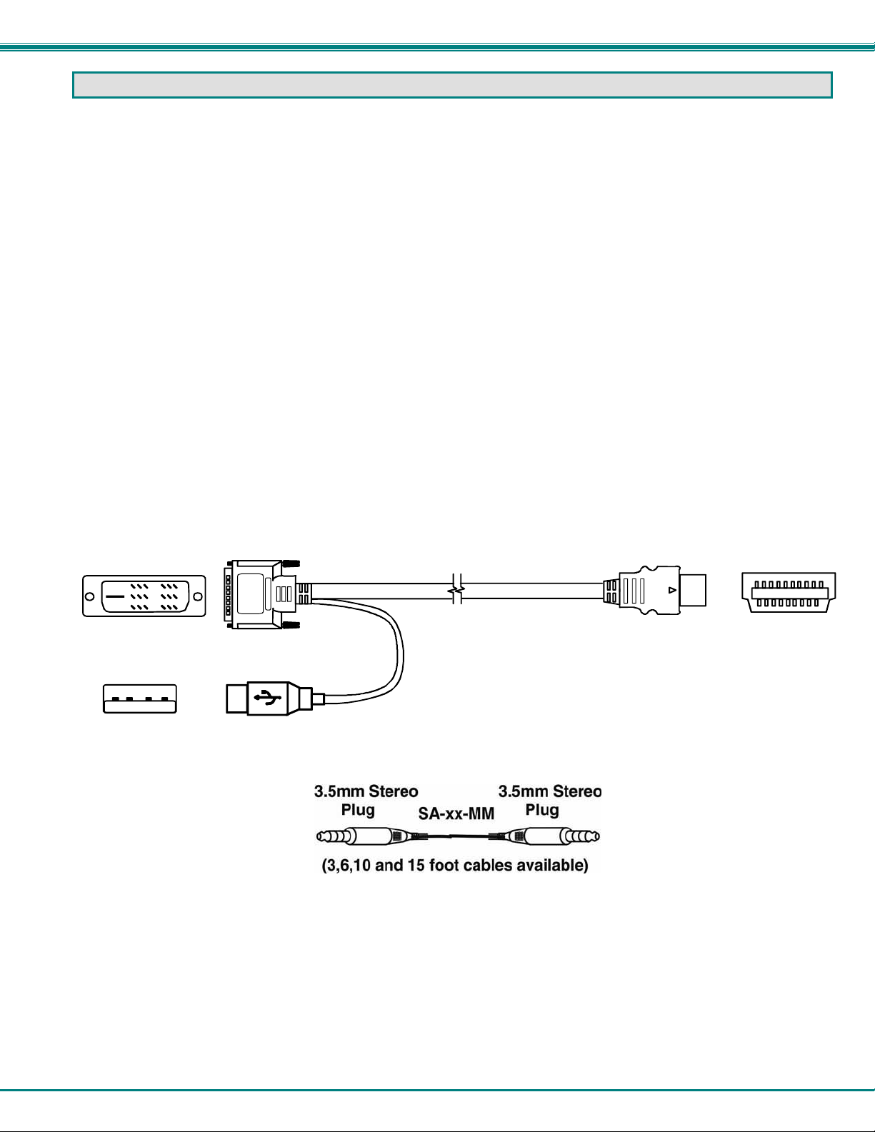
• USB-DHEXT-xx-MM cable for each CPU being connected to the switch- for DVI monitor, USB keyboard, and USB mouse
support- available in 3, 6,10, and 15 foot lengths
• An SA-xx-MM cable with 3.5mm stereo plug on each end for each audio source to be connected (models with audio support
only) SA-xx-MM cables are available from NTI in 3,6,10 and 15 foot lengths
where:
xx is the length of the cable in feet
MM indicates male-to-male connector
Cables can be purchased from Network Technologies Inc by calling (800) 742-8324 (800-RGB-TECH) in the US and Canada or
(330) 562-7070 (worldwide).
DVI-D-Male
USB Type A
Male
DVI-D-Male
Single Link
USBType A Male
USB-DHEXT-xx-MM
HDMI Type A Male
(3,6,10 and 15 foot cables av ailable)
HDMI Type A
Male
2
Page 7
NTI UNIMUX SERIES USB KVM SWITCH
DEFINITIONS
• USB Composite
Device
• USB Hub
A USB device that contains multiple endpoints each representing input devices that cannot be separated
(i.e. a keyboard with a built-in mouse)
A USB device that allows one or more USB input devices to plug in to the USB. The hub has exactly one
upstream port with one or more downstream ports which input devices connect to
• CPU
Enclosure that contains the operating system and processor (i.e. Sun with SPARCstation5, Windows 95
with Pentium II)
• Input Device
• System
Keyboard or Mouse
One or more CPUs connected to one or more switches controlled by one or more input devices
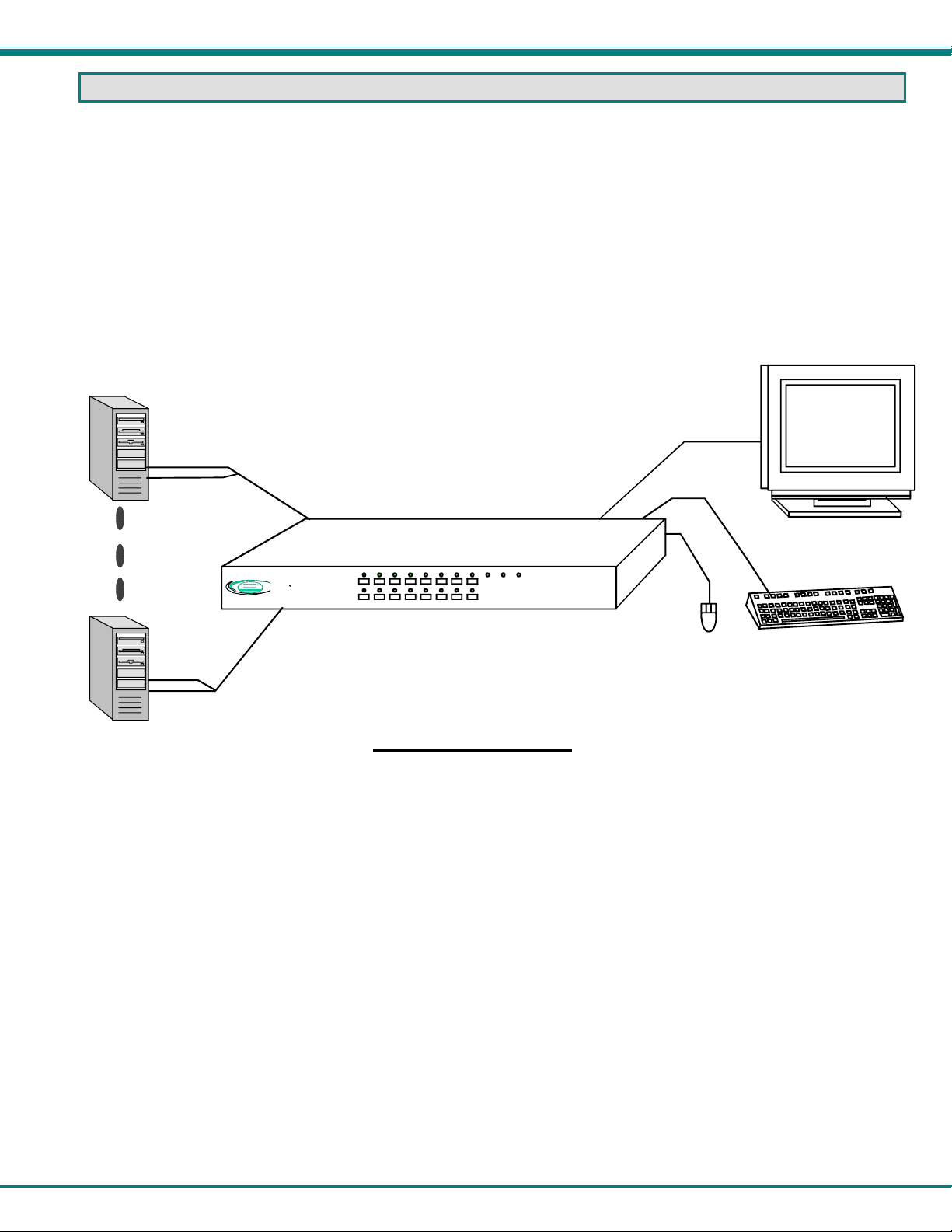
USB CPU
USB-DHEXT-xx-MM
(required-not supplied)
Existing
cable
DVI Enabled
Monitor
USB CPU
Front View of UNIM UX -D VI-8 HD
R
R
UNIMUX
NTI
Network Technologies Inc
USB-DHEXT-xx-MM
(required-not supplied)
Typical Application
Existing
Command
Scan
Broadcast
87654321
161514131211109
USB
cables
USB Keyboard
Mouse
3
Page 8
NTI UNIMUX SERIES USB KVM SWITCH
Front View of UNIM UX -D VI-1 6HD
NTI
Networ k Tec hnol ogie s Inc
R
UNIMUX
R
Scan
87654321
161514131211109
CommandBroadcast
1
2
3
Rear View of UNIMUX-DVI-16HD
4
250V,2A
5 8
NTI
1275 Danner Dr
Aurora, OH 44202
www.networktechinc.com
Tel:330-562-7070
Fax:330-562-1999
R
RS232
6
7
CPU 9CPU 10CPU 11CPU 12CPU 13CPU 14CPU 15CPU 16
CPU 1CPU 2CPU 3CPU 4CP U 5CPU 6CPU 7CP U 8
MONITOR
RS232
DDC
ON
8
1
9
10
11
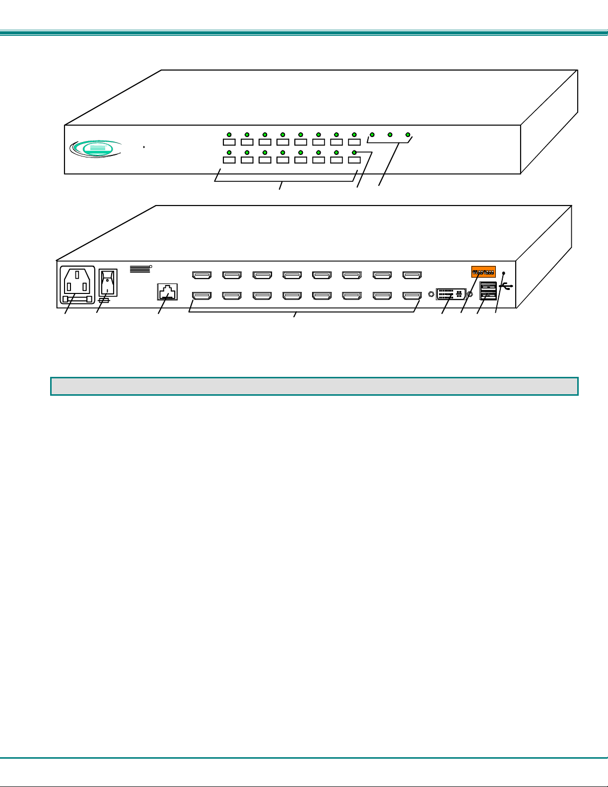
FEATURES AND FUNCTIONS
1. CPU Select Switches- push to manually switch to a specific CPU or change the switch operating mode
2. CPU Status LEDs- for visual indication of connection between the user and a specific CPU.
3. Mode Status LEDs- for visual indication of switch operating mode
4. IEC Connector w/Built-in 2A 240VAC Replaceable Fuse- for attachment of the IEC power cord to power the UNIMUX
5. Switch- for powering ON and OFF the UNIMUX
6. RS232- RJ45 serial connector- for attachment of RS232 control cable
7. CPU x- HDMI Type A female connector- for connection of the cable from the CPU(s)
8. MONITOR- female DVI connector- for connecting DVI cable from user monitor
9. RS232- DIP switches for configuring switch address when RS232 is used
10. USB- USB type A female connector- for connection of user USB keyboard and mouse
11. DDC- for refreshing the DDC information between the monitor and CPU
4
Page 9

NTI UNIMUX SERIES USB KVM SWITCH
RACKMOUNTING INSTRUCTIONS
This NTI switch was designed to be mounted to a rack or to sit on a desktop. It includes rackmount ears to make attachment to a
rack easy, and rubber feet to be applied to the bottom of the case if it will instead sit on a flat surface. If this will sit on a flat
surface, simply apply the rubber feet to the bottom of the case in each of the 4 corners.
To Mount in a Rack
1. Attach the ears to the switch using the 6-32x3/16" flat Phillips-head screws (6) provided as shown in the illustration below.
The holes in the ears should line up with pre-threaded holes in the sides of the NTI switch. Tighten the screws securely.
Front of Switch
NTI Switch
6-32x3/16"
Flat Head
Screws
(Provided)
Rackmount Ear
Figure 1- Secure rackmount ears to switch
2. Install 4 cage nuts (not supplied) to the rack in locations that line up with the holes in the mounting ear on the NTI switch.
3. Secure the NTI switch to the rack using four rack screws (10-32, 12-24, M6, etc.- not supplied). Each screw should be of
sufficient length to go completely through the NTI mounting ear, rack frame and fully engage all threads in the cage nut.
Be sure to tighten all mounting screws securely.
4. Attach all cables securely to the switch and where necessary supply adequate means of strain relief for cables.
Rack Screws
(not supplied)
NTI Switch
Rack
Cage Nuts
(not supplied)
Figure 2- Secure switch to a rack
5
Page 10

NTI UNIMUX SERIES USB KVM SWITCH
INSTALLATION
1. It is not necessary to turn the CPUs or monitors OFF during this installation.
2. Connect a DVI-to-DVI cable (should have come with the monitor) from a DVI monitor to the “MONTOR” connector on the rear
of the UNIMUX (See Fig. 3 below.)
NTI
1275 Danner Dr
Aurora, OH 44202
www.networktechinc.com
Tel:330-562-7070
Fax:330-562-1999
250V,2A
DVI Enabled
Monitor
R
RS232
Rear View of UNIMUX-DVI-16HD
Existing Cable
Mating Face of
DVI Male
CPU 9CPU 10CPU 11CPU 12CPU 13CPU 14CPU 15CPU 16
CPU 1CPU 2CPU 3CPU 4CP U 5CPU 6CPU 7CPU 8
DVI-D-Male
MONITOR
RS232
DDC
ON
8
1
Figure 3- Connect a DVI monitor
3. Connect the male USB type A connector on the keyboard cable to either one of the two USB type A female connectors
labeled with the USB symbol ( ) on the rear of the UNIMUX.
4. Connect the male USB type A connector on the mouse cable to the remaining USB type A female connector labeled with the
USB symbol on the rear of the UNIMUX.
250V,2A
NTI
1275 Danner Dr
Aurora, OH 44202
www.net workte ch inc.com
Tel:330-562-7070
Fax:330-562-1999
R
RS232
Rear View of UNIMUX-DVI-16HD
CPU 9CPU 10CPU 11CPU 12CPU 13CPU 14CPU 15CPU 16
MONITOR
USB Type A Female
CPU 1CPU 2CPU 3CPU 4CP U 5CPU 6CP U 7CPU 8
USB Type A Male
RS232
ON
DDC
8
1
USB Type A
Male Connecto rs
USB Keyboard
USB
Mouse
Figure 4- Connect the device(s)
6
Page 11

NTI UNIMUX SERIES USB KVM SWITCH
D
5. Connect each CPU to the USB switch using a USB-DHEXT-xx-MM (xx=3, 6, 10, or 15 foot) cable for each video and input
device connection – REQUIRED (not supplied). (See Fig. 5 below.) Cables are available from NTI.
Input Device Port
USB Type A Female
Video Port
DVI Female
Video Connector
R
NTI
1275 Danner Dr
Aurora, OH 44202
www.n etwork techi n c.com
250V,2A
Tel:330-562-7070
Fax:330-562-1999
RS232
Rear View of Windows U SB CP U
Rear View of UNIMUX-DVI-16HD
CPU 9CPU 10CPU 11CPU 12CPU 13CP U 14CPU 15CPU 16
CPU 1CPU 2CPU 3CPU 4CP U 5CPU 6CP U 7CPU 8
USB Type A Male
USB-DHEXT-xx-MM
(3,6,10 and 15 foot cables available)
Mating Face of
VI Male
MONITOR
RS232
ON
DDC
8
1
HDMI Type A
Video Connector
Mating Face of
HDMI Type A Male
Figure 5- Connect each CPU
7. Connect the AC power cord with IEC connector to the UNIMUX. (See Fig. 6 below.)
Rear View of UNIMUX-DVI-16HD
250V,2A
NTI
1275 Danner Dr
Aurora, OH 44202
www.networktechinc.com
Tel:330-562-7070
Fax:330-562-1999
R
RS232
IEC Connector
Power cord
Figure 6- Connect the power cord
RS232
DDC
CPU 9CPU 10CPU 11CPU 12CPU 13CPU 14CP U 15CPU 16
CPU 1CPU 2CPU 3CP U 4CP U 5CPU 6CPU 7CPU 8
MONITOR
ON
18
7
Page 12

NTI UNIMUX SERIES USB KVM SWITCH
RS232 Connection
If the RS232 is going to be used, connect one end of the CAT5 patch cable (supplied) to the port labeled “RS232” on the rear of
the UNIMUX. Plug the other end of the CAT5 cable into either the RJ45-to-DB9 or RJ45-to-DB25 adapter supplied, and connect
the adapter to the RS232 port on the control terminal. Follow the instruction under “RS232 Control” on page 13 for configuration
and use of the RS232 control feature.
250V,2A
NTI
1275 Danner Dr
Aurora, OH 44202
www.networktechinc.com
Tel:330-562-7070
Fax:330-562-1999
R
RS232
CAT5 Patch Cable
(supplied)
Rear View of UNIMUX-DVI-16HD
CPU 9CPU 10CPU 11CPU 12CPU 13CPU 14CPU 15CPU 16
CPU 1CPU 2CPU 3CPU 4CP U 5CPU 6CPU 7CP U 8
RJ45-to-DB9 Adapter
(supplied)
or
RJ45-to-DB25 Adapter
(supplied)
Control Terminal
MONITOR
VGA
Multi-Scan
Monitor
RS232
DDC
ON
8
1
Figure 7- Connect RS232 control terminal
8
Page 13

NTI UNIMUX SERIES USB KVM SWITCH
Power-Up Sequence
For optimum performance and communication of DDC information between the monitor and CPU, we recommend powering up
the system as described below:
1. Power-up the monitor.
Note: Make sure your monitor is in digital DVI mode (not analog DVI) for video to be viewed.
2. With the keyboard and mouse connected to the UNIMUX, power-up the UNIMUX.
Note: It is recommended that the monitor be powered-ON before powering on the UNIMUX in order for DDC information
to be properly communicated.
3. Power ON the CPU(s).
USB input devices (keyboard and mouse) can be hot plugged to and from the UNIMUX at any time.
Limitations
• Only USB input device or hub cables can be connected to the UNIMUX at the USB Type A female ports. (See Features and
Functions on page 3, item 11.)
• A USB hub (single or multi-port) can be used provided only USB input devices are plugged into it.
• Only a USB Windows or SUN keyboard or USB mouse may be connected to the USB port on a USB MAC keyboard
• A maximum of 8 input devices may be connected to the UNIMUX either directly or through hubs.
See Fig. 8 for some examples of input device combinations that can be used with the UNIMUX.
Typical Installation- 1 keyboard, 1 mouse
USB Type A
Male Connectors
USB Windows Keyboard
USB
Mouse
USB Windows Keyboard
USB Windows Keyboard
Multiple keyboards and mice
USB MAC Keyboard
MAC USB keyboard and mouse through hub
Mouse
USB
Hub
USB
USB
Hub
USB
Mouse
USB
Mouse
USB MAC Keyboard
MAC USB keyboard and mouse
USB
Mouse
Figure 8- Compatible device combinations
9
Page 14

NTI UNIMUX SERIES USB KVM SWITCH
USING THE UNIMUX DVI KVM SWITCH
Once the UNIMUX is properly connected, the UNIMUX will enable a connection to be made between the CPUs attached to its
VIDEO and CPU ports and the monitor and input devices attached to the MONITOR and USB Device ports. The LEDs on the
control panel of the UNIMUX will illuminate depending on w hich port (and corresponding CPU) is being connected to the monitor
and input devices.
The UNIMUX can be controlled by three methods:
• front control panel using touch-switches and LEDs
• keyboard control through Command Mode
• RS232 control (page 13)
Front Panel Control
There is a touch-switch and LED on the front panel of the UNIMUX for each CPU the switch will connect the monitor and
input devices to. Pressing any touch-switch on the front panel of the UNIMUX will connect the corresponding CPU to the monitor
and input devices.
Holding down any front panel touch-switch for more than 2 seconds will cause the UNIMUX to cycle through all modes of
operation including COMMAND, BROADCAST, SCAN, and NORMAL (described in "Command Mode" below). The three MODE
LEDs on the front panel indicate which mode is selected. Release the touch-switch when the LEDs indicate the desired mod e.
When no mode LEDs are illuminated the user is in Normal Mode controlling directly the CPU to which the user is connected
through the UNIMUX.
Keyboard Control
Keyboard control of the UNIMUX can be achieved using Command Mode (below). The keyboard can be used to control all
functions of the UNIMUX as an alternative to using the front panel on the UNIMUX.
By pressing <Ctrl> + < ` > (accent/tilde key), the user can enter Command Mode. Once in Command Mode, typing a series of
commands will cause the UNIMUX to connect the user to any one CPU connected to the switch. Pressing the <Esc> key will exit
Command Mode.
Command Mode
In order to control the UNIMUX with the keyboard connected, Command Mode must be enabled. To enter Command Mode from
the keyboard:
Press
When the COMMAND LED is illuminated, all 3 status lights on the keyboard will illuminate (if they aren't already due to caps lock,
scroll lock, and/or num lock) to indicate that Command Mode is enabled and the following functions are available:
Basic Command Functions
Function: Keystroke:
Increment Port
Decrement Port
Toggle Scan Mode
ON and OFF
Toggle Broadcast Mode
ON and OFF
Sets scan time-out
period for each port.
I
D
S
B
T
or
or
(The SCAN Mode LED will
also toggle ON and OFF)
(The Broadcast Mode LED
will toggle ON and OFF.)
-
(0-2)
x
Ctrl
(select the next higher port
ex. 03 04)
(select the next lower port
ex. 02 01)
(0-9)
-
x
10
(ACCENT/TILDE
~
`
`
-
KEY)
(0-9)
x
KEY SYMBOLS LEGEND:
or
PRESS EITHER KEY
CHORDED SEQUEN CE- PRESS CONSECU TIVELY
AND KEEP KEYS PR ESSED UNTIL ALL ARE PRESSED .
+
PRESS CONSECUTI VEL Y
-
(xxx from 00 2 t o 255. ie . T002
would set the time-out period
for 2 seconds)
Page 15

NTI UNIMUX SERIES USB KVM SWITCH
Selects a specific
port
Configure port to connect
To a MAC CPU
Configure port to connect
To a WINDOWS or SUN
CPU
Exit Command Mode
P
Esc
(0-9)
-
x
FYI: The user must exit Command Mode to type to a CPU.
To exit Command Mode, either hold down any touch-switch on the
front panel for more than 2 seconds, OR press <ESC> on the
keyboard.
(0-9)
-
x
(Pxx would be P01, P02, etc.)
Scan Mode
To activate Scan Mode, press <S> from the Command Mode menu. When in Scan Mode the switch scans to each port with a
CPU powered-ON. (The SCAN LED on the front panel will illuminate and remain ON while in Scan Mode. ) The port with the CPU
powered-ON remains active while in use until it becomes idle for the configured dwell time (default time-out perio d is 5 seconds)
before switching to the next powered-ON CPU port. See Command Mode section above for configuring the scan d well time.
To deactivate Scan Mode, press <S> from the Command Mode menu again.
Note: The keyboard and mouse must remain idle for the full scan dwell time before the switch selects the next active
port.
Broadcast Mode
To activate Broadcast Mode, press <B> from the Command Mode menu. (The BROADCAST LED on the front panel will
illuminate and remain ON while in Broadcast Mode.) Broadcast Mode enables the user to type characters to all powered-ON
CPUs simultaneously. To deactivate Broadcast Mode, press <B> from the Command Mode menu again.
Note: The user must type somewhat slowly when in Broadcast Mode (less than 20 wpm) and cannot use the
<Backspace> key.
Normal Mode
When all of the UNIMUX mode LEDs are OFF the user is in Normal Mode, controlling the CPU to which the user is connected
through the UNIMUX.
No Sun Sleep Mode
Note: It is necessary to configure a Sun CPU (most versions) such that the Sleep Mode is not enabled. If the Sun CPU
goes into Sleep Mode either automatically or manually, the user must reboot the Sun CPU in order to resume use of the
Sun CPU.
To disable the Sleep Mode, perform the following steps:
1. Select "Power Manager"
2. Look for "Device Idle Time Before Power Saving Starts"
3. Select "Always ON"
4. Look for "Override Device Idle Time For:"
5. Make sure neither "Monitors" nor "Disks" are selected.
11
Page 16

NTI UNIMUX SERIES USB KVM SWITCH
Select Country Code
It is possible to configure the UNIMUX to emulate a specific international Sun keyboard regardless of what actual keyboard is
connected. This is recommended when the CPU needs the layout code (i.e. a SUN CPU) and the keyboard doesn't have an
explicit layout code (i.e. some Windows keyboards). To do this, manually set the UNIMUX to indicate the international keyboard
identification number to the CPU using the following procedure;
1. Connect the keyboard to be used to the UNIMUX
2. Enter Command Mode
3. Type Lxx, where xx is the number from the list below that corresponds to the desired country code
4. Exit Command Mode
Note: If any SUN CPUs are connected to the UNIMUX, they must be rebooted. Keyboard configuration is only read by
SUN CPUs on startup.
Country Codes
00 Auto Detect 13 International (ISO) 26 Swedish
01 Arabic 14 Italian 27 Swiss/French
02 Belgian 15 Japan (Katakana) 28 Swiss/German
03 Canadian-
Bilingual
04 Canadian-French 17 Latin American 30 Taiwan
05 Czech Republic 18 Netherlands/Dutch 31 Turkish
06 Danish 19 Norwegian 32 UK
07 Finnish 20 Persian (Farsi) 33 US
08 French 21 Poland 34 Yugoslavia
09 German 22 Portuguese
10 Greek 23 Russia
11 Hebrew 24 Slovakia
12 Hungary 25 Spanish
16 Korean 29 Switzerland
Figure 9- Country Codes for international SUN keyboards
For more on international SUN keyboards, see page 19.
Mice and Trackballs with MACs
The UNIMUX can be configured to enable full functionality between mice and trackballs having two or more buttons and USB
MAC CPUs. By default, the ports on the UNIMUX are configured for use with WINDOWS and SUN CPUs and have no specia l
translation for using multi-function mice and trackballs when a MAC CPU is connected. Using the commands <M> + <x> + <x>
(xx = port number), or <W> + <x> + <x> in Command Mode (page 10), either enable or disable this feature as needed for each
port.
NOTE: Be sure to re-configure port for connection to a WINDOWS or SUN CPU if a MAC CPU is removed and a
WINDOWS or SUN CPU is then connected.
12
Page 17

NTI UNIMUX SERIES USB KVM SWITCH
RS232 CONTROL
RS232 enables the UNIMUX to be remotely controlled via RS232. To control the UNIMUX via RS232 the user has three options:
• write a program that runs on a PC using the Command Protocol (page 15)
• use the NTI Switch Control Program (page 16) provided on the CD
• use the SerTest program (page 16) provided on the CD
RS232 Connections and Configuration
Remote Connection
The RS232 Interface (optional) is designed to meet the RS232C standard and can be controlled from a ny CPU or other controller
with an RS232 communications port. The pin-out for the RJ45 connector on the unit is as follows:
RS232 (RJ45) CONNECTOR
PIN SIGNAL FUNCTION
1 - No connection
2 - No connection
3 RX+ Receive data (TXD at host)
4 GND Ground
5 - No connection
6 TX+ Transmit data (RXD at host)
7 - No connection
8 - No connection
A 5 foot patch cable and two adapters, RJ45-to-DB9 and RJ45-to-DB25, have been provided for connection to most CPUs (see
page 8).
Baud Rate
The baud rate can be changed by powering down the unit, changing the 8 position RS232 DIP switch on the rear of the UNIMUX,
and then powering back up. This table shows how to set the baud rate. (Fig. 10 shows switches in their factory default position.)
DIP
SWITCH
3 2
OFF OFF 2400
OFF ON 9600 (default)
ON OFF 19200
ON ON 38400
BAUD RATE
ON
1
RS232
8
Figure 10- RS232 DIP switches
Unit Address and Loop Back
To allow multiple units to be controlled from a single CPU serial port, the RS232 con trol interface is designed to allow "daisy
chaining" up to 15 units. By setting the appropriate RS232 DIP switches, each unit can be given a unique address (1-15). Then
the unit will only respond to commands on the bus if its address is embedded in the c ommand. Use the following table to set the
unit address.
13
Page 18

NTI UNIMUX SERIES USB KVM SWITCH
DIP SWITCH UNIT ADDRESS
8 7 6 5
OFF OFF OFF OFF 0 (not valid)
OFF OFF OFF ON 1 (default)
OFF OFF ON OFF 2
OFF OFF ON ON 3
OFF ON OFF OFF 4
OFF ON OFF ON 5
OFF ON ON OFF 6
OFF ON ON ON 7
ON OFF OFF OFF 8
ON OFF OFF ON 9
ON OFF ON OFF 10
ON OFF ON ON 11
ON ON OFF OFF 12
ON ON OFF ON 13
ON ON ON OFF 14
ON ON ON ON 15
Note: Switch 4 on the RS232 DIP switch is not used.
In order to connect multiple switches (up to 15) with RS232 connections to the same CPU, an NTI Matrix-Y-1 cable must be used.
Connect the Matrix-Y-1 cable between the RJ45-to-DB9 serial adapter (provided with the RS232 option) and the CPU as shown in
Fig. 11.
CPU
Figure 11- RS232 connection with Matrix-Y-1 cable
Figure 12- Pinout of Matrix-Y-1 cable
RS232
Serial Port
RJ45
TO DB9
SERIAL
ADAPTER
First Unit
Matrix-Y-1
RJ45
TO DB9
SERIAL
ADAPTER
CAT5 CABLE CAT5 CABLE CAT5 CABLE
RS232
NTI
SWITCH
SWITCH
Second Unit Last Unit
Matrix-Y-1 Matrix-Y-1
RS232
NTI
Wiring Schematic of Matrix-Y-1 cable
(Unit #1)
23
33
555
Note: The "loop back" RS232 DIP switch (RS232 DIP
switch 1) should be ON for each unit in the chain.
Note: The maximum combined
RJ45
TO DB9
SERIAL
ADAPTER
RS232
NTI
SWITCH
RS232 cable length between the
CPU and any NTI switch cannot
9D Female9D Male 9D Male
(Source)
(Unit #2)
Not connected to
source connector
22
7
Jumper
8
1
Jumpers
4
6
14
Page 19

NTI UNIMUX SERIES USB KVM SWITCH
Command Protocol
RS232 commands supported by the unit are defined below. All command strings should be terminated with a <CR> (carriage
return). When a command is sent, the entire string is echoed back along with a response from the addressed unit as shown in the
command definitions. All characters in the command string should be upper case, and all numbers below 10 should have a
leading 0 (ex: 1 = 01). As command strings are sent, the inner character delay cannot exceed 500 milliseconds.
(RESPONSE RECEIVED)
Figure 13- RS232 Communication Illustrated
Note: To use this command protocol, the user is required to write a program that will send an entire command string all
at once, not character by character. Programs that send one character at a time (such as HyperTerminal) cannot be used
to control the UNIMUX. Alternatively, the user may use the NTI Switch Control Program or SerTest to control the
UNIMUX via RS232 (see page 16).
Legend: (All numbers must be two digits)
SW : Switch (01-15) (Unit Address)
OP : Output (User) Port (01)
IP : Input (CPU) Port (01-MAXINPUTS)
<CR> : Carriage Return (Hex 0xD)
Note: For units with one output (user) port, use 01 for the output selection.
Command Definitions
Command String Good Response Description
CS SW,IP,OP *<CR> Connect Output (User) Port To specific Input (CPU) Port
RO SW,OP *<CR>IP<CR> Read Connection For Output (User) Port to Input (CPU) Port
RS SW *<CR> Internal Reset
RU SW *<CR>IP,OP<CR> Read Unit Size
SS SW,00 *<CR> Disable Autostatus feature (see below)
SS SW,01 *<CR> Enable Autostatus feature (see below)
GO SW,OP *<CR>go SW,OP:IP<CR> Read connection of a Output (User) Port to Input (CPU) Port
GM SW,00 *<CR>go OP,IP (all ports)<CR> Read connection matrix of all Output (User) ports
If the first field is not a known command (as listed above) or SW field is different from the unit address programmed at the DIP
switch (page 13), the command will be ignored. If the SW field corresponds to the unit address, but if the syntax is wrong after
this field, the switch will answer with a bad response ?<CR>.
Autostatus
When Autostatus is enabled, any output (user) -to-input (CPU) connection change in the UNIMUX will cause an Autostatus
message to be sent via RS232 to the administrator. The format of the message would be "pc SW,OP:IP<CR>"
Example of an Autostatus message:
pc 01,01:04<CR>
which means "At the switch with unit address 01, the output (User) (01) has changed connection to input (CPU) port 04."
Note: An Autostatus message to the administrator will be delayed by any RS232 traffic being received by the switch
from the administrator.
By default, Autostatus is disabled and must be manually enabled.
CPU
(COMMAND SENT)
CS 01,01,03<CR>
CS 01,01,03<CR>
* <CR>
SWITCH AT UNIT ADDRESS 01
RS232
RS232
(COMMAND RECEIVED)
CS 01,01,03<CR>
(ECHO)
CS 01,01,03<CR>
(RESPOND)
* <CR>
(different response format than RO command)
15
Page 20

NTI UNIMUX SERIES USB KVM SWITCH
NTI Switch Control Program For Windows 9X, NT, 2000, XP, Vista, and 7
The NTI Switch Control Program is an easy and powerful graphical program that controls NTI switches through an RS232
interface. The NTI Switch Control Program is included on the CD packaged with the UNIMUX. The NTI Switch Control
Program is downloaded by clicking on the link "Download NTI Switch Control Program".
To install the NTI Switch Control Program after downloading
1. Locate the Setup.exe in the directory the program was downloaded to and double-click on it
2. Follow the instructions on the screen
Note: In order to use the NTI Switch Control Program to control the UNIMUX, the UNIMUX RS232 port must be set at a
baud rate of 9600 bps (see page 13).
The NTI Switch Control Program performs best on monitors set to a screen resolution of at least 800 X 600. Instruction for using
the NTI Switch Control Program is available by opening "MSCP Help" in the "NTI" program group once the program has been
installed and is open on the screen.
To open "MSCP Help" from the Windows desktop
1. Click on START
2. Click on PROGRAMS
3. Click on NTI
4. Click on MSCP Help
SerTest- RS232 Interface Test Program
This software allows a user to test the functions of an NTI server switch, matrix switch or Multi-user/Multi-platform/Single-user
switch RS232 interface. The SerTest program is automatically loaded when installing the NTI Switch Control Program as
described above. The SerTest program, located in the NTI program group, generates a main menu with the 4 selections
described below:
Main Options
• Switch Operations
• Ethernet Operations
• Setup Options
• About SerTest
If Matrix Operations is selected, the following menu is displayed:
SWITCH OPERATIONS
1) Reset Unit
- send a reset command to the switch
- the current unit address is displayed in parentheses
2) Reset All Units
- send an internal reset command to all switches
3) Connect Output/User to an Input/CPU
- connect an output to an input
4) Connect All Outputs/Users to an Input/CPU (not applicable to this model)
- connect all outputs to an input
5) Connect Audio Output/User to an Input/CPU (not applicable to this model)
- connect an output to an input
6) Connect All Audio Outputs/Users to an Input/CPU (not applicable to this model)
- connect all outputs to an input
7) Change Mute Status for Audio Output/User (not applicable to this model)
- mute or un-mute the Audio port output
- send commands to the unit.
- set ethernet connection variables (not applicable to this model)
- set COM port, baud rate, and unit address
- display the program version
16
Page 21

NTI UNIMUX SERIES USB KVM SWITCH
8) Change V olume for Audio Output/User (not applicable to this model)
- change Audio port output volume
9) Read Connection for Output/User
- read what input is connected to the specified output
a) Read Connection for Audio Output/User (not applicable to this model)
- read what input is connected to the specified output
b) Read Mute Stat us and Volume for Audio Output/User (not applicable to this model)
- read the volume and the mute status of the specified output
c) Read Unit Size
- read the switch size (number of inputs and outputs)
d) Read Unit Vers ion/Revision String (not supported by this model)
- read a string containing the switch version, type, and size
e) Save I/O Connections into Unit Memory (not applicable to this model)
- save the connections into switch memory bank
f) Restore I/O Connections from Unit Memory (not applicable to this model)
- restore the connections from switch memory bank
g) Save All Units I/O Connections into Units Memory (not applicable to this model)
- save the connections into switch memory bank, command for all switches
h) Restore All Unit s I/O Connections from Units Memory (not applicable to this model)
- restore the connections from switch memory bank, command for all switches
i) Change All Units Baud Rate (9600/COM1)
- change RS232 Baud rate of all switches
- the current baud rate and serial port are displayed in parentheses
ETHERNET OPERATIONS (not applicable to this model)
SETUP OPTIONS
1) select Com port current: (COM1:)
- select PC serial port
- the current PC serial port is displayed in parentheses
2) select Baud rat e current: (9600)
- select PC serial port baud rate
- the current baud rate is displayed in parentheses
3) set unit Address current: (1)
- select the unit address of the switch to be connected to by this program
- the current address is displayed in parentheses
For any selection that requires user input, the user is prompted. When commands are sent to the UNIMUX, the command string
and UNIMUX responses are echoed to the screen. All commands generated by the program are formatted according to the
information provided in sections above. If any transmission problems are detected, an error message is displayed.
Press <Esc> o
r
<Enter> to back out to the main menu and press again to exit.
17
Page 22

NTI UNIMUX SERIES USB KVM SWITCH
KEYBOARD FEATURES
The keyboard configuration of each CPU is saved in the UNIMUX. For example, if the CPU attached to Port 2 had CAPS LOCK
and NUM LOCK selected the last time that CPU was accessed, then they will automatically be set when that CPU is accessed
again.
Keyboard-To-Computer Translation
The UNIMUX enables a mixture of otherwise incompatible peripheral computer components to be connected together. This is
accomplished by performing keyboard-to-computer translations automatically (i.e. translate a MAC keyboard and mouse to a
Windows type CPU). The chart below shows the capabilities of devices controlling certain CPU types.
Translation Capabilities
CPU
Device Sun Mac Windows
Sun Keyboard
AT101 Keyboard
Mac keyboard
Apple Pro Keyboard
Sun Mouse
Wheel Mouse
Apple Mouse
Translation Tables
Use the charts below to type SUN’s additional keys with Win95 and Apple keyboards:
SUN Extra Keys
WINxx or Mac Keyboards Sun Extra Keys
Space Bar + F1 Stop
Space Bar + F2 Again
Space Bar + F3 Props
Space Bar + F4 Undo
Space Bar + F5 Front
Space Bar + F6 Copy
Space Bar + F7 Open
Space Bar + F8 Paste
Space Bar + F9 Find
Space Bar + F10 Cut
Space Bar + F11 Help
Space Bar + F12 Compose
Space Bar + Up Arrow Volume +
Space Bar + Down Arrow Volume Space Bar + Left Arrow Mute
Full functionality Full functionality Full functionality
Extra keys emulation Power key emulation Full functionality
Extra keys emulation Full functionality Full functionality-except
Extra keys emulation Extra Keys not supported
(Eject, Mute, Volume+,
Volume-)
Full functionality Full functionality Full functionality
Full functionality Full functionality Full functionality
Right button emulation Full functionality Right button emulation
(See Fig. 14 on page 19 for reference.)
Application Key
Full functionality
Power Key Emulation
Win95 Keyboards Mac CPU Sun CPU
SB+RT Arrow Power Power
Mouse Click Equivalents
To emulate right-button click using an Apple 1-button
mouse, hold down the CMND key (key with open
apple insignia) while pressing the mouse button.
18
Page 23

NTI UNIMUX SERIES USB KVM SWITCH
Esc
~
`
Tab
Caps Lock
Shift
Ctrl Alt
Esc
F1 F2 F3 F4 F5 F6 F7 F 8 F9 F10 F11 F12
~
`
Tab
Caps Lock
Shift
Ctrl Alt
Windows Logo Key
Help
Stop
Props
Front
Open
Find Cut
Again
Undo
Copy
Paste
esc
~
`
tab
caps Lock
shift
control
alt
option
Esc
Tab
Control
Shift
Capslock Alt
Command Key
Apple Pro USB Keyboard
Meta Key Meta Key
Backspace
Enter
Shift
Alt
Ctrl
Typical 101 Ke yboard
Backspace
Enter
Shift
Alt
Ctrl
Application KeyWindows Logo Key
Windows USB Keyboard
F12 F11
F10 F8 F7 F6 F5 F4 F3 F2 F1
F9
delete
return
shift
alt
controloption
Command Key
Backspace
Return
Shift
Compose
SUN USB Keyboard
Print
Screen
SysRq
F13 F14 F15
Alt
Graph
Scroll
Lock
Pause
Break
Num
Lock
Num
Lock
num
lock
clear
=/
Num
Lock
Enter
Enter
*
enter
CD Eject
Key
Enter
Power
key
Figure 14- Keyboard Layouts
International Sun Keyboards
The UNIMUX can recognize international layouts for Sun keyboards. In order to use an international Sun keyboard, follow this
procedure:
1. Power-OFF the CPU connected to the UNIMUX
2. Connect the international keyboard to be used to the UNIMUX
3. Power-ON the CPU connected to the UNIMUX
It is also possible to configure the UNIMUX to emulate a specific international Sun keyboard regardless of what actual keyboard is
connected. This is recommended when the CPU needs the layout code (i.e. a SUN CPU) and the keyboard doesn't have an
explicit layout code (i.e. some Windows keyboards). To do this, manually set the UNIMUX to indicate the international keyboard
identification number to the CPU by following the instruction on page 12.
19
Page 24

NTI UNIMUX SERIES USB KVM SWITCH
DDC
The UNIMUX is designed to transfer DDC information from the monitor to the CPU so that the CPU is able to update EDID data
about the monitor it connects to.
DDC information is downloaded from the attached monitor and stored in the UNIMUX when the UNIMUX is first power-ON
(monitor must be ON first), or by pressing the “DDC” button after the UNIMUX is powered-ON (used when hot-plugging the
monitor).
Note: Make sure your monitor is in digital DVI mode (not analog DVI) for video to be viewed and for the proper EDID table
to be communicated to the CPU.
Once the DDC information is recorded, the UNIMUX will transfer it to each connected CPU.
250V,2A
NTI
1275 Danner Dr
Aurora, OH 44202
www.networktechinc.com
Tel:330-562-7070
Fax:330-562-1999
R
Rear View of UNIMUX-DVI-16HD
CPU 9CPU 10CPU 11CPU 12CPU 13CPU 14CPU 15CPU 16
RS232
CPU 1CPU 2CP U 3CP U 4CPU 5CP U 6CPU 7CPU 8
DDC Button
ON
1
MONITOR
RS232
DDC
8
Figure 15-DDC Button Location
AUDIO SUPPORT
(Optional)
Models with audio support include 3.5mm stereo jacks for connection to audio sources and an output de vice. Audio from either
the same sources as the video, keyboard, and mouse or from separate sources (any standard line level audio source
(1.23Vrms/3.47Vp-p max.)) will be heard through devices such as self-powered stereo speakers or headphones.
Audio signals are switched along with the keyboard, mouse and video signals using the buttons on the UNIMUX switch.
Connections to “AUD IN” ports will switch at the same time as like-numbered “CPU” ports when controlling the switch. For
example, if “CPU 1” is switched to “CPU 2”, then “AUD IN 1” will also switch to “AUD IN 2”.
Figure 16- Rear View of UNIMUX-DVIA-8HD
20
Page 25

NTI UNIMUX SERIES USB KVM SWITCH
TROUBLESHOOTING
PROBLEM:
SOLUTION:
PROBLEM:
SOLUTION:
PROBLEM:
SOLUTION:
PROBLEM:
SOLUTION:
Keyboard Errors
Check cable connections on each CPU and the switch.
No Video
• Check cable connections on each CPU and the switch. Verify that keyboard and video connect from each
CPU to matching ports. After reconnecting, CPU may need to be re-booted in order to sense the monitor
connection.
• Make sure monitor is configured for digital DVI video (not analog DVI). See your monitor instructions for how
to do this.
• Press the “DDC” button on the back of the unit.
No Mouse Movement
Check cable connections of mouse. Verify that mouse driver was loaded.
Unit is not displaying full 1920x1200, 1920x1024 works OK.
If source identifies monitor as MTK 5380 (which is the monitor used to test the UNIMUX)
press the DDC button on the back of the unit.
21
Page 26

NTI UNIMUX SERIES USB KVM SWITCH
INDEX
addressing, 13
Audio support, 20
Autostatus, 15
baud rate, 13
Broadcast mode, 11
Command mode, 10
control methods, 10
country codes, 12
CPUs supported, 1
daisy-chaining, 13
DDC, 20
definitions, 3
devices supported, 1
features, 4
front panel control, 10
Installation, 6
international keyboard layouts, 19
Keyboard control, 10
keyboard features, 18
keyboard translation, 18
limitations, 9
MAC mice and trackballs, 12
materials supplied, 2
Matrix-Y-1 cable, 14
power-up sequence, 9
Rackmounting, 5
RS232 commands, 15
RS232 Control, 13
RS232 pinout, 13
Scan mode, 11
SerTest, 16
Sun sleep mode, 11
Switch Control Program, 16
WARRANTY INFORMATION
The warranty period on this product (parts and labor) is two (2) years from the date of purchase. Please contact Network
Technologies Inc at (800) 742-8324 (800-RGB-TECH) or (330) 562-7070 or visit our website at http://www.networktechinc.com
for information regarding repairs and/or returns. A return authorization number is required for all repairs/returns.
MAN005 Rev 1/17/13
22
 Loading...