

Page 1

PT100 Portable TAP
User Guide
Revision 1.0
Page 2

Contents
Chapter 1 Preface 2
Introduction . . . . . . . . . . . . . . . . . . . . . . . . . . . . . . . . . . . . . . . . . . . . . . . . . . . . . . . . . . . . . . . . . . . . . . . . . . . . . . . . . . . . . . . . . . . 2
Product Features and Benefits . . . . . . . . . . . . . . . . . . . . . . . . . . . . . . . . . . . . . . . . . . . . . . . . . . . . . . . . . . . . . . . . . . . . . . . . . . . . 2
Chapter Overview . . . . . . . . . . . . . . . . . . . . . . . . . . . . . . . . . . . . . . . . . . . . . . . . . . . . . . . . . . . . . . . . . . . . . . . . . . . . . . . . . . . . . . 3
Conventions used in this manual . . . . . . . . . . . . . . . . . . . . . . . . . . . . . . . . . . . . . . . . . . . . . . . . . . . . . . . . . . . . . . . . . . . . . . . . . 3
Chapter 1 Getting Started 4
Inspect Packaging . . . . . . . . . . . . . . . . . . . . . . . . . . . . . . . . . . . . . . . . . . . . . . . . . . . . . . . . . . . . . . . . . . . . . . . . . . . . . . . . . . . . . . 4
Connecting the PT100 to the Network. . . . . . . . . . . . . . . . . . . . . . . . . . . . . . . . . . . . . . . . . . . . . . . . . . . . . . . . . . . . . . . . . . . . . 4
Chapter 2 PT100 Portable 100MB Aggregation TAP 5
Traffic Flow Map . . . . . . . . . . . . . . . . . . . . . . . . . . . . . . . . . . . . . . . . . . . . . . . . . . . . . . . . . . . . . . . . . . . . . . . . . . . . . . . . . . . . . . . 5
Front Panel . . . . . . . . . . . . . . . . . . . . . . . . . . . . . . . . . . . . . . . . . . . . . . . . . . . . . . . . . . . . . . . . . . . . . . . . . . . . . . . . . . . . . . . . . . . . 5
Port Status Indicators . . . . . . . . . . . . . . . . . . . . . . . . . . . . . . . . . . . . . . . . . . . . . . . . . . . . . . . . . . . . . . . . . . . . . . . . . . . . . . . . . . . 6
Rear Panel. . . . . . . . . . . . . . . . . . . . . . . . . . . . . . . . . . . . . . . . . . . . . . . . . . . . . . . . . . . . . . . . . . . . . . . . . . . . . . . . . . . . . . . . . . . . . 6
Chapter 3 Installing the PT100 Portable TAP 7
Appendix A Product Specifications 9
Specifications . . . . . . . . . . . . . . . . . . . . . . . . . . . . . . . . . . . . . . . . . . . . . . . . . . . . . . . . . . . . . . . . . . . . . . . . . . . . . . . . . . . . . . . . . . 9
Appendix B Troubleshooting 10
Appendix C Contacting Technical Support 11
PT100 User Guide 1
Page 3
Preface
!
Introduction
This manual will introduce you to the PT100 and describe its functionality so you can make the best use of your new
product.
100 Portable TAP (Traffic Access Point) is ideal for 100M network troubleshooting. The PT100 offers
The PT
innovative features such as passive live network monitoring, POE (Power Over Internet) pass-through, and 1G monitor
ports. The PT
troubleshoot your network segments quickly and effectively, using only a single network analyzer. The PT
use of gigabit monitor interfaces where directional traffic is combined, or aggregated, thus allowing easy analysis on
dedicated capture devices or portable computers. The PT100’s two gigabit monitor interfaces allow for up to two
different tools to capture identical full-duplex traffic flowing over a single Ethernet segment. This TAP is not designed
for use with POE+ networks.
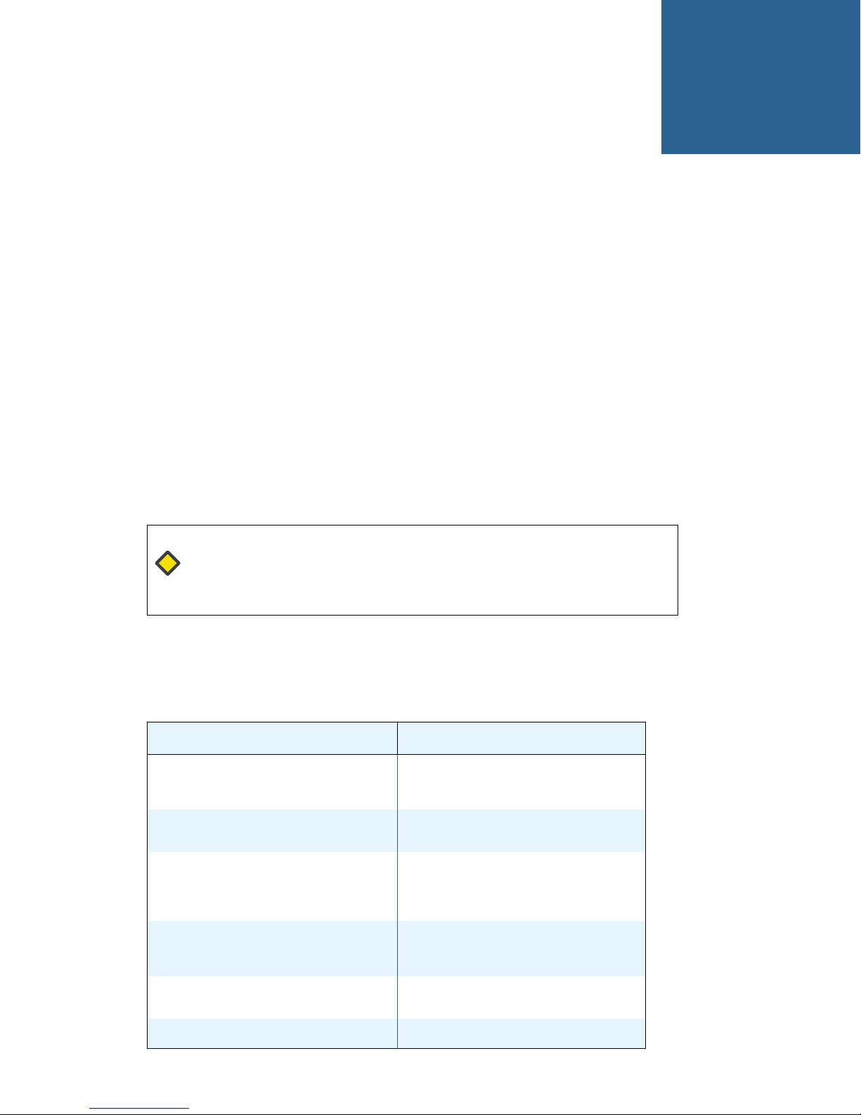
Caution: The information and procedures in this manual should be used by a
professional network engineer. Make sure to take all necessary precautions to ensure
that the installation and implementation of this product do not interfere with normal
network operations.
100 can be deployed with little network downtime. Once deployed, the PT100 enables you to
100 makes
Product Features and Benefits
Features Benefits
Link Failure Propagation (LFP)
LinkLock Mode
Passive Network Ports
Aggregating Monitor Ports
Gigabit Monitoring Ports
Power Over Ethernet (POE) Passive
PT100 User Guide 2
Allows the attached network devices to
detect if the link state is lost on adjacent
network devices.
Creates a permanent physical connection
between the live network ports.
Ensures the live network continuity is
maintained during power state changes.
Guaranteed 100% live link uptime even on
power loss.
Enables monitoring of full-duplex network
traffic from each interface, ensuring 100%
data is passed to the monitor tools.
Ensures all data from live network ports is
captured on a single monitoring interface.
Passes POE to attached supporting devices.
Page 4
Chapter Overview
i
!
Chapter 1, Getting Started on page 4 provides a general overview of the PT100 including instructions for connecting
the PT100.
Chapter 2, PT100 Portable 100MB Aggregation TAP on page 5 provides information on getting started with the PT100,
including information on installing the hardware.
Chapter 3, Installing the PT100 Portable TAP on page 7 explains how to install the PT
Appendix A, Product Specifications on page 9 provides technical specifications for the PT
Appendix B, Troubleshooting on page 10 provides tips and guidelines for troubleshooting.
Appendix C, Contacting Technical Support on page 11 lists the contact details for Technical Support.
Conventions used in this manual
Caution: A “Caution” advises the reader about situations that may result in incorrect,
poor or no operation of the product. A Caution also advises of situations that may
cause personal injury or may cause damage to the product or other property.
PREFACE
Chapter Overview
100.
100 Portable TAP.
Note: A “Note” contains essential user information.
Tip: A “Tip” contains useful or other interesting information.
PT100 User Guide 3
Page 5

Getting Started
Inspect Packaging
Remove the PT100 from the packaging and ensure that the following items are included:
• PT100 Portable PoE Passive Ethernet TAP with two (2) 100M Copper RJ45 TAP Ports and two (2) 1 Gigabit Copper
RJ45 Monitoring Ports
• 1 External Power Supply
If any of the above items are missing, please contact us immediately so we can resolve the issue. Refer to Appendix C,
Contacting Technical Support on page 11 for contact information.
Connecting the PT100 to the Network
1
Before you Install
Before you start the installation, the following steps must be performed:
1 Determine where you want to tap into your network. The location must have access to an approved power outlet (100
to 240 VAC 50/60 Hz).
2 Verify the types of cables required. If a crossover cable is required, without the PT100 inserted in the link, it will still be
required. These two cables replace the existing cable that is removed when you install the TAP.
3 Obtain cables of the appropriate types and lengths.
4 Set all of the network device interface modes. It is recommended that your LAN devices are set to operate at 100M
fixed full duplex where possible.
PT100 User Guide 4
Page 6
PT100 Portable 100MB
Aggregation TAP
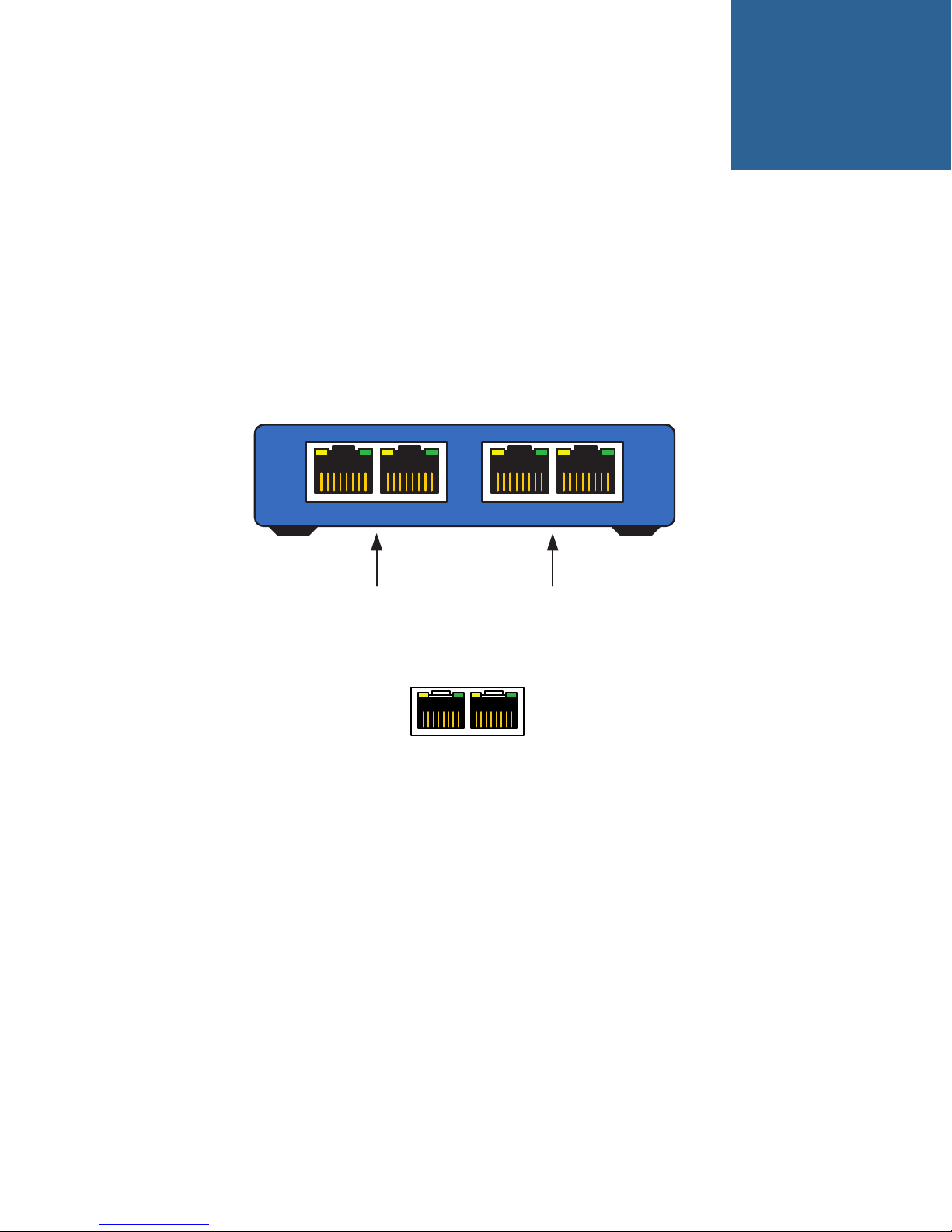
The PT100 Portable 100MB Aggregation TAP is an in-line network device that combines two directional traffic
streams into a single output port or monitoring interface as data traverses a network media.
Front Panel
2
LIVE PORTS
100M Network Ports 1G Tool Ports
Port Status Indicators
Green:
ON = Link (device connected)
Flashing = Activity on link
Yellow:
LED Not used
LNK/ACTLNK/ACT
LNK/ACT
MONITOR PORTS
LNK/ACT
PT100 User Guide 5
Page 7
Rear Panel
Traffic Flow Map
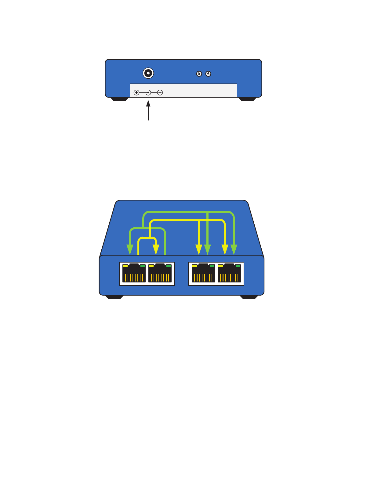
The MONITOR PORTS will only aggregate the same network traffic out of both gigabit ports.
PT100 PORTABLE 100MB AGGREGATION TAP
Rear Panel
5VDC
Power
Connector
LIVE PORTS
LNK/ACTLNK/ACT
LNK/ACT
MONITOR PORTS
LNK/ACT
PT100 User Guide 6
Page 8
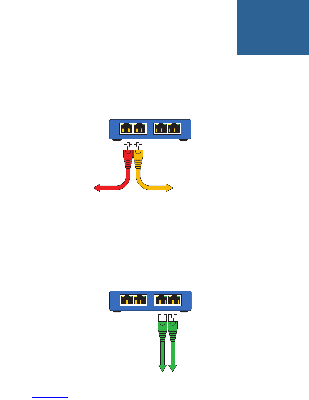
Installing the PT100 Portable TAP
Crossover
Cable MDIX
Straight
Cable MDI
LNK/ACT
LIVE PORTS
LNK/ACT
LNK/ACTLNK/ACT
MONITOR PORTS
1 Place the PT100 Portable TAP at the location where you want to monitor your network.
2 Route two Ethernet cables of the appropriate types and connect your network devices to the LIVE PORTS on the front
of the PT
• A straight-through cable should be attached to the left most LIVE PORT.
• A crossover cable should be attached to the right most LIVE PORT.
100.
3
3 Check the Link/Activity indicators on the network devices’ ports to verify that data is flowing through the LIVE
PORTS on the PT
duplex. A
setting all port speeds to
PT
100 from the link, and verify that the devices can link without the TAP. Once the devices link, and port speed and
duplex are verified to be
4 If either one of the LIVE PORTS do not link, ensure that you have set the link speed on your network devices to 100M
full or half duplex. The PT
100. If the network devices do not have a link, be sure that all ports are set to 100M full or half
10/100/1000 device will, at times, try to link at 1000M and fail (since the PT100 does not support1000M). If
100M full duplex does not solve the problem, a crossover cable may be required. Remove the
100M full-duplex, reinsert the PT100.
100 allows traffic to flow through it at 10M, but does not display link lights on the LIVE
PORTS or forward data to the MONITOR PORTS.
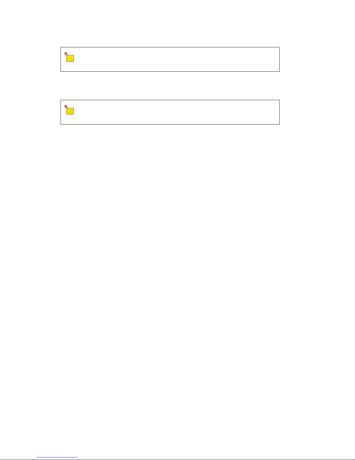
5 Attach your monitoring device to the MONITOR PORTS on the front of the TAP unit using Cat 5 Ethernet cables. The
1000M only. Be sure the monitoring tool is set to Auto or 1000M.
LNK/ACT
LNK/ACT
LIVE PORTS
LNK/ACTLNK/ACT
MONITOR PORTS
MONITOR PORTS are
PT100 User Guide 7
Monitoring
Device 1
Monitoring
Device 2
Page 9
INSTALLING THE PT100 PORTABLE TAP
Note: Straight or crossover cables can be used on the MONITOR PORTS as they are
Auto-MDIX (Media Dependent Interface Crossover) capable.
6 Check the Link/Activity indicators on the monitoring device and the PT100 to verify that data is flowing out of the
monitor ports to the monitoring device(s).
Note: If the PT100 fails to power up, or fails to show activity on all ports, ensure
that the power source is turned on.
PT100 User Guide 8
Page 10

Product Specifications
!
Specifications
A
Number of TAPs
Number of Ports
Network Ports
Monitor Ports
Network Port Speed
Monitor Port Speed
Size (WxHxD)
Weig ht
Ambient Temperature
Operating Relative Humidity
Storage Temperature
Voltag e (AC/DC )
Current (nominal)
Maximum Power Consumption
1
4
2
2
100M
1G
(3.942 x 1.20 x 3.942) inches
(100.1 x 30.48 x 100.1) millimeters
8 ounces
0°C to +40°C/ +32°F to +104°F
90% non-condensing
-20°C to +70°C/ -4°F to +158°F
5 volts
.9 amps
<5 watts
Specifications are subject to change without notice.
Safety information
Document reference symbol. If the product is marked with this symbol,
refer to the product documentation to get more information about the
product.
Warning A WARNING in the documentation denotes a hazard that can cause injury
CAUTION A CAUTION in the documentation denotes a hazard that can damage
Do not proceed beyond WARNING or CAUTION notices until the hazardous conditions are
understood and appropriate steps have been taken.
Servicing
There are no user-serviceable parts inside this product. Any servicing, adjustments, maintenance or repairs must be
performed by service-trained personnel only.
PT100 User Guide 9
or death.
equipment.
Page 11

Troubleshooting
If you are experiencing problems with the PT100 or its connectivity, please refer to the following table, or contact
Technical Support at the locations listed in Contacting Technical Support on page 11.
Problem Solution
B
No Link on network devices, no link on PT100 LIVE
PORTS
No link on PT100 LIVE PORTS, link on network
devices
No link on network devices, link on one of the PT100
LIVE PORTS
Verify the speed and the duplex on network devices.
Speed must be set to 100MB full or half duplex (100MB
full-duplex preferred). If it remains set to auto
negotiate 10/100/1000, devices may try to link at
1000MB and fail.
Verify the speed and the duplex on network devices.
The PT100 allows a 10MB connection between
network devices, but does not show the link on PT100
LIVE PORTS. It also does not pass data to the MONITOR
PORTS.
A crossover cable is required and should be connected
to the left most PT100 LIVE PORT.
PT100 User Guide 10
Page 12

Contacting Technical Support
For additional assistance with the PT100 Portable TAP System, please contact one of our Technical Customer Support
Centers:
European Support Center
C
Phone
North and South American Support Center
Phone
On the web
http://www.networkcritical.com > Support > Open a support case
+44 (0)118 954 3210
+1 (716) 558-7280
PT100 User Guide 11
 Loading...