

Page 1
Operation Manual
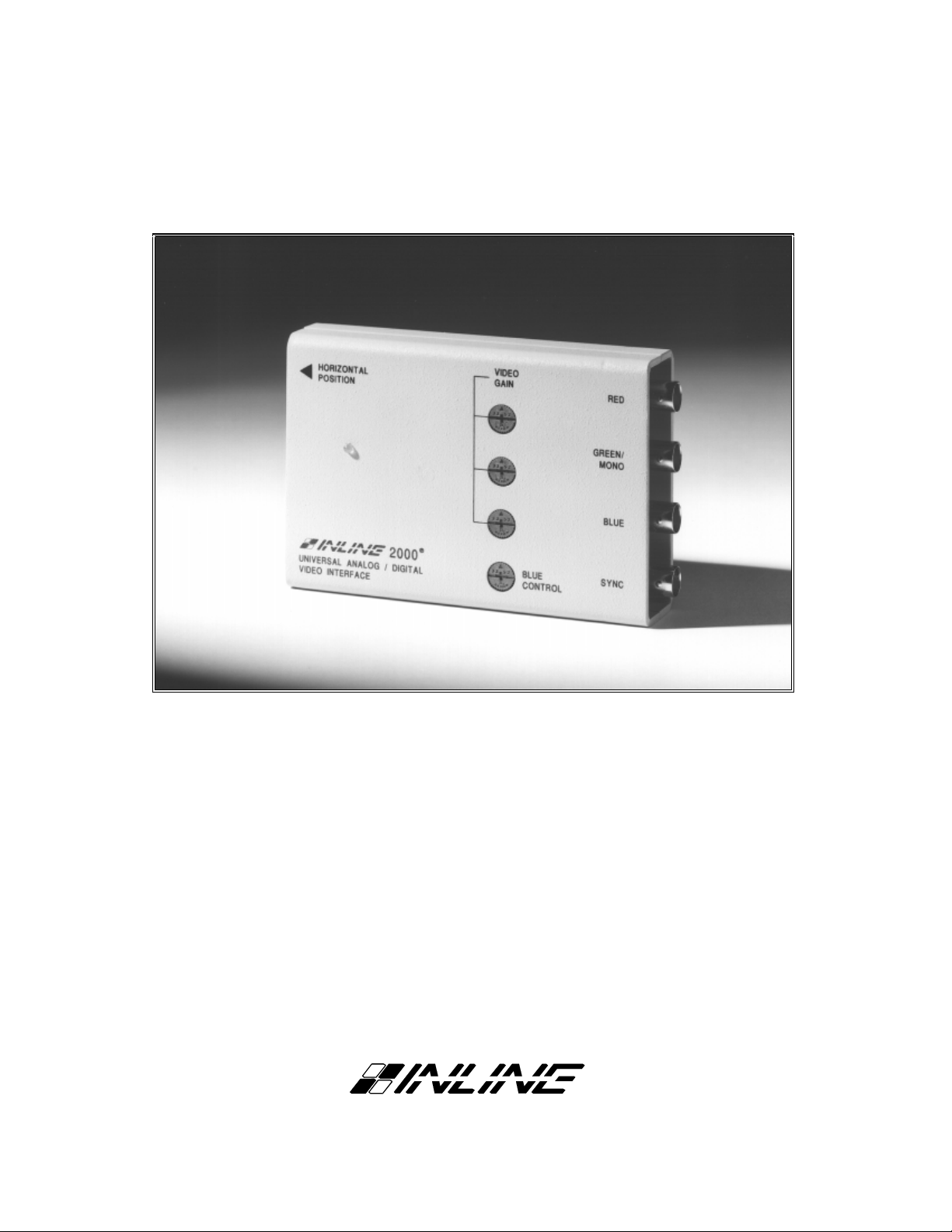
Universal Video Interface Series
IN2000 Analog / TTL / ECL Video Interface
IN2001 Analog / TTL / ECL Video Interface
®
Page 2

TABLE OF CONTENTS
Description / Features....................................................................................................................1
IN2000 / IN2001 Differences .........................................................................................................2
Input Compatibility .......................................................................................................................2
Output Compatibility.....................................................................................................................3
IN5100 Series Monitor Loop Cables ............................................................................................3
Installation......................................................................................................................................4
Application Diagram...........................................................................................................5
Horizontal Position Control..........................................................................................................6
RGB Gain Controls........................................................................................................................6
Blue Enhancement Control...........................................................................................................6
Control Location Diagrams.................................................................................................7
Internal Controls............................................................................................................................8
Horizontal Blanking Control...............................................................................................9
Dip Switch Settings ........................................................................................................................9
Factory Default Settings......................................................................................................9
Sync on Green Output.........................................................................................................9
Monochrome Output...........................................................................................................9
Disable / Enable Horizontal Position Control...................................................................10
Enable Blanking Control...................................................................................................10
IN2001 Internal Fuses..................................................................................................................10
IN5100 Series Cables - Partial Listing .......................................................................................11
IN2000 / IN2001 Input Pin Configuration........................................................................11
Interfacing to Computers with BNC Outputs...........................................................................12
Specifications................................................................................................................................13
Included Accessories / Optional Accessories...................................................................14
Troubleshooting............................................................................................................................14
Warranty.......................................................................................................................................16
Page 3
DESCRIPTION
The IN2000 and IN2001 are universal computer video interfaces designed to work with Analog, TTL,
and ECL computer video signals. Like other INLINE interfaces, the IN2000 / IN2001 carry out three
primary functions:
Signal Splitting - these interfaces allow for the simultaneous connection and viewing of both the
computer’s local monitor and a second output device such as a large screen data projector,
monitor, or color printer.
Electronic Interfacing - Computer video output signals come in three main varieties: Analog,
TTL Digital, and ECL Digital. Several different signal sync formats are used including RGBS
(composite sync), RGBHV (separate horizontal and vertical sync signals), RGsB (sync on the
Green video signal), and Monochrome with Composite Sync. The IN2000/2001 will accept any
of these signal types and formats, outputting the signal in the standard RGBS Analog video
format.
Physical Interfacing - Computers employ many different types of video output connectors,
making it difficult to hook up computers directly to data projection devices. The IN2000 /
IN2001 simplify interfacing, routing, and switching tasks by acting as universal adapters.
Through the use of IN5100 Series removable monitor loop input cables, the IN2000 / IN2001
can be attached to virtually any computer and will provide a video output signal on four BNC
connectors which can easily be connected to an RGB display device.
1
The IN2000 / IN2001 are not scan converters. The data projector, monitor, or other
output device must be compatible with the horizontal scan rate output by the
computer video card.
The IN2000 / IN2001 Universal computer video interfaces are fully automatic, offering easy operation
and the following features:
♦ 100 MHz Bandwidth - High performance interface design ensures that video signals will be
interfaced with no loss of image detail.
♦ Universal Design - units will operate Analog Video, TTL Digital Video, and ECL Digital Video
input. TTL and ECL digital signals are converted to analog video, allowing output signals to be run
over long distances on high resolution coaxial cables.
♦ IN5100 Series Monitor Loop Cables - dozens of specialized input cables are available which allow
the IN2000 / IN2001 to be attached to over 95% of the computers on the market (IN5100 Series
input cables are not included with the IN2000 / IN2001, but are required for operation). This design
prevents obsolescence - users may buy the universal interface and IN5100 cable(s) they need today
and add additional cables in the future as their needs change.
♦ Loop-Through Output - provides a passive output signal for the local computer monitor.
♦ Flexible Output Signal Formats - RGBS (standard), RGsB, and Composite Monochrome.
♦ Horizontal Position Control - allows picture to be centered precisely on the data display screen.
♦ RGB Gain Controls - Red, Green, and Blue levels can be calibrated and output gain boosted to
compensate for long cable runs (up to 100’ depending on signal horizontal scan frequency).
♦ Blue Enhancement - improves visibility of digital input signals which contain a lot of blue elements.
©1996-1997 - INLINE, INC. IN2000 / IN2001 OPERATION MANUAL - REV. 2.1 12/11/99
Page 4

2
IN2000 AND IN2001 DIFFERENCES
These two interfaces are virtually identical in function, features, and operation with only a few minor
differences as detailed in the chart below:
IN2000 IN2001
Power Supply: External Power Adapter Internal Power Supply
Size: 1.1" H x 4.8" W x 3.27" D 2" H x 6.75" W x 4.33" D
Adjustment Pots: Top mounted, hand adjustable Recessed pots, adjustable with
tweeker tool
Dip Switches: Internal Externally Accessible
INPUT COMPATIBILITY
The IN2000 / IN2001 universal interfaces will accept video signals with horizontal scan frequencies
between 15.7 KHz and 145.0 KHz. In order to interface to different computers, the appropriate IN5100
Series Monitor Loop Cable must be used. For more information and a complete listing of IN5100
Monitor Loop Cables, see Pages 3 & 11. Common analog, TTL, and ECL signals are listed below along
with compatible signal formats.
Analog Video
Common signals (partial listing): VGA, S-VGA, XGA, XGAII,
Compatible Input Signal Formats: w RGBS
TTL Digital Video
Common signals (partial listing): CGA, EGA, MDA/Hercules, Apple II/IIE,
Compatible Input Signal Formats: w 1, 2, 3, 4 or 6 bit TTL video with separate composite
ECL Digital Video
Compatible Input Signal Formats: w 1 or 3 bit ECL video with separate composite sync
MACII (CX, FX, CI, SI, LC, Quadra, Centris),
Sun Sparc Station, Silicon Graphics Iris Indigo.
w RGBH&V
w RGsB
w RsGsBs
w Monochrome video combined with sync
w Monochrome with separate composite sync
w Monochrome with separate H & V syncs
MAC/MAC+, MAC SE, IBM 3400 Series.
sync signal
w 1, 2, 3, 4 or 6 bit TTL video with separate H & V
sync signals
w 1 or 3 bit ECL video with separate H & V syncs
IN2000 / IN2001 OPERATION MANUAL - RE V. 2.1 12/11/99 ©1996-1997 - INLINE, INC.
Page 5

While the input connector on the IN2000/2001 looks like a standard 15 pin HD VGA
connector (15 pins in three rows), this input uses proprietary pin connections to
accommodate the unit’s universal design. VGA and other signals can not be
attached directly to the input without the appropriate IN5100 Series loop cable.
OUTPUT COMPATIBILITY
The IN2000 / IN2001 output an analog video signal in the RGBS format (Red, Green, Blue, and
composite sync) on four BNC connectors. The output signal is compatible with many data projectors and
monitors. In addition to the default RGBS output format, the IN2000 / IN2001 may be set to output
RGsB or Composite Monochrome Video with Sync by changing the dip switch settings (see Pages 8 &
9).
A special version of the IN2000 is available for installations requiring an RGBHV output. This unit
features a 15 Pin HD Female connector on the output and may be ordered using the following model
designation: IN2000SP RES911722.
VGA, MACII, and high resolution workstation video cards operate in several different modes
encompassing a wide range of resolutions and horizontal scan rates. The IN2000 and IN2001 are not
scan converters and the data projector or monitor must be compatible with the horizontal scan rate output
by the computer video card. Please check the documentation for both the computer video card and the
data projection device in order to ensure compatibility.
3
IN5100 SERIES MONITOR LOOP CABLES
Unlike Dedicated Video Interfaces which are designed to work with one specific type of computer
graphic signal and feature a permanently attached input cable, Universal Interfaces such as the IN2000 /
IN2001 function with a wide variety of input signals. These interfaces derive a great deal of their
flexibility and "universality" through the use of detachable input cables. The IN5100 Series includes
dozens of special input cables, each designed for a specific type of computer graphic signal or computer
model. For example, the IN5101A is designed for VGA / S-VGA / XGA type signals, while the
IN5161A works with MACII type video signals. Four main characteristics determine the make up of an
IN5100 Series cable:
w Analog or Digital signal
w Sync Format (RGBS, RGBHV, RGsB / RsGsBs, Monochrome)
w Video Output Connector Type (15 pin HD, 15 pin D, 25 Pin D, etc.) and pin-outs
w External or Internal Installation
Analog or Digital
Analog Cables are designated with the letter "A" (IN5101A, IN5133A, IN5161A). ECL cables
also receive the "A" designation (IN5126A, IN5137A ).
TTL Digital Cables are designated with the letter "T" (IN5106T, IN5122T, IN5158T).
External or Internal Cables
Most IN5100 Series cables are inserted in-line between the computer’s video output and the monitor
input cable (see diagram on page 5). Some computers and terminals do not offer an external video
output, and INLINE has designed special internal IN5100 Series cables for several of these models.
Each internally mounted IN5100 Series cable includes an instruction sheet describing the installation
procedure.
A partial listing of the most popular IN5100 Series Monitor Loop Cables is located on Page 11.
©1996-1997 - INLINE, INC. IN2000 / IN2001 OPERATION MANUAL - REV. 2.1 12/11/99
Page 6
4
INSTALLATION
This section offers step-by-step instructions for installing the IN2000 / IN2001. A detailed application drawing
showing all equipment connections is included on the next page.
1. Turn the computer and computer monitor off. Disconnect the computer monitor (if present) from the
video output port on the computer.
2. The IN5100 Series cables have a pass-through connector (Male and Female) on one end. The pass-
through end is connected to the computer and local monitor. Connect the male side of the pass-
through connector to the computer’s video output port.
3. Connect the local computer monitor (if present) to the female side of the IN51XX pass-through. If
no local monitor is used, a termination plug is required for analog type video signals.
It is very important that the female side of loop-through cables receive a 75 ohm signal
termination when interfacing analog video signals. If no termination is provided, the
output of the interface will be very overdriven, appearing very bright with poor contrast.
The termination is also required by certain video cards (VGA, newer MACII, etc.) because
they sense the attached monitor at boot up and set the card for the appropriate mode.
Two of the most popular termination plugs are listed below:
IN5101A Cable Use an IN9031 15-pin HD VGA terminator plug (not included).
This emulates a color VGA monitor.
IN5161A Cable Use an IN9056 15-pin D MAC II terminator plug (not included).
This emulates a 13"/14" Apple monitor.
4. Connect the other end of the IN51XX cable (single male 15 pin HD connector) to the input connector
on the IN2000 / IN2001.
The IN2000 / IN2001 must be located immediately adjacent to the computer. Do not
attempt to lengthen the IN51XX loop-through cable. If the IN51XX cable is extended,
ghosting or other signal problems may occur. Also, the local monitor cable should not
be more than 6 - 12’ long.
5. Connect the IN2000 / IN2001 RGBS output (4 BNC connectors) to the data display device’s RGBS
input, using four high resolution BNC cables or a multi-conductor RGBS "snake". The IN7000,
IN7100, and IN7600 series high resolution cables are well suited for this purpose. Take care while
making connections to insure that the red output is connected to the red input, green output to the
green input, etc.
6. Apply power to the interface. The green power LED will light to indicate the unit is receiving
power.
IN2000: Use the 12V 500 mA included power supply.
IN2001: Use a standard power cable (included on U.S. units).
7. Complete the installation by turning the computer and computer monitor on. If required, adjust the
horizontal position and RGB gain controls as detailed on Pages 6 and 7.
IN2000 / IN2001 OPERATION MANUAL - RE V. 2.1 12/11/99 ©1996-1997 - INLINE, INC.
Page 7
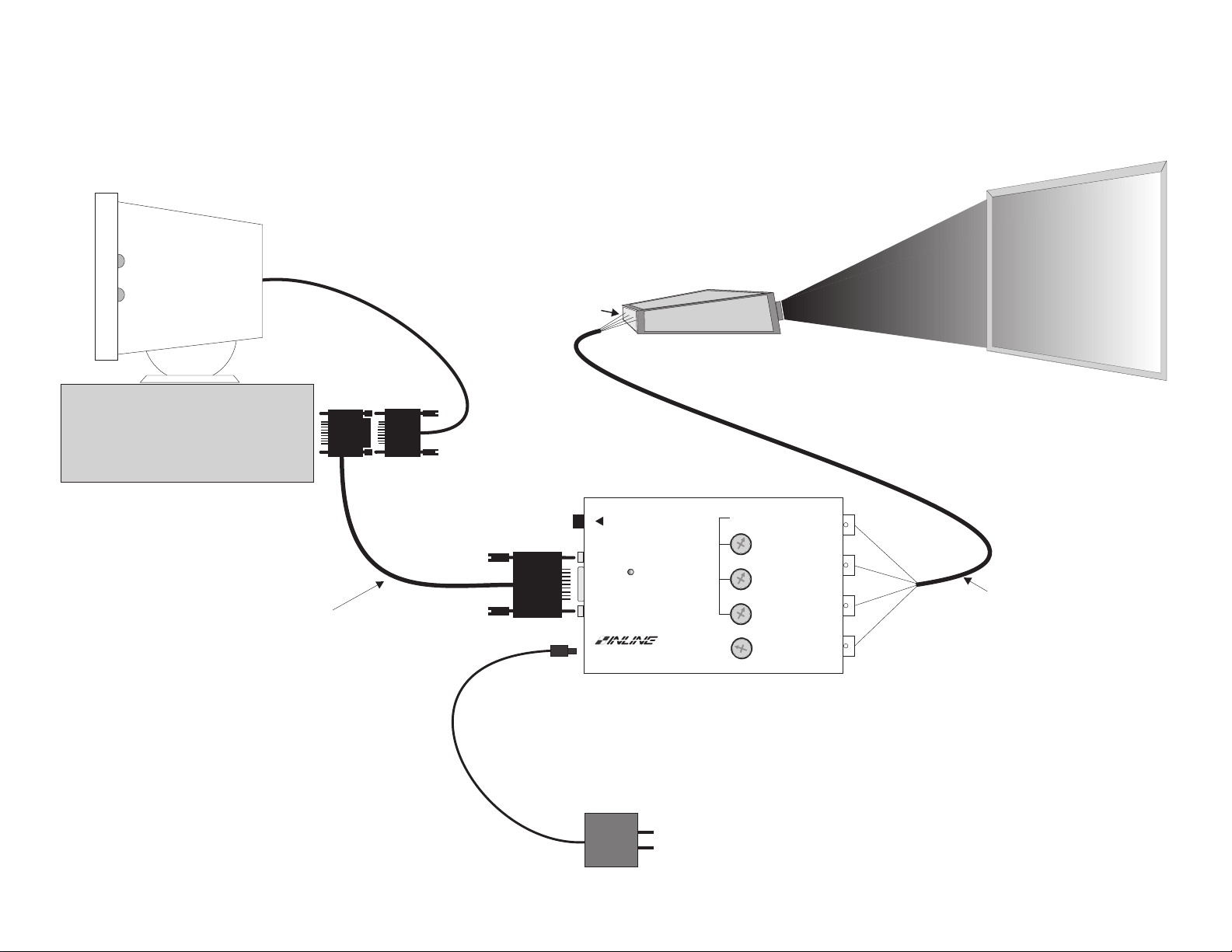
Application Diagram
IN2000 / IN2001
Local Monitor
Computer CPU
RGBS Input
Data Projector / Monitor
IN2000 / IN2001
HORIZONTAL
POSITION
VIDEO
GAIN
RED
IN5100 Series
Monitor Loop Cable
UNIVERSAL ANALOG / DIGITAL
VIDEO INTERFACE
Power Supply
12V / 500 mA
2000
GREEN/
MONO
BLUE
®
BLUE
CONTROL
SYNC
IN7000-4 / IN7100-4
RGBS Cable
Page 8

6
HORIZONTAL POSITION CONTROL
The location of the horizontal position control is diagrammed on the next page. The horizontal position
control adjusts the position of the image on the data display device from left to right (it has no effect on
the local computer monitor). This control adjusts through a range of 14 full knob rotations, offering very
fine control over the image position. The pot emits a soft click if either extreme position is reached.
Many data projectors and monitors have their own horizontal position control, and the interaction of the
display device’s horizontal control and the interface’s horizontal control may result in a dark image on the
data display. The following procedure is suggested to ensure best results:
1. Adjust the IN2000 / IN2001 horizontal position control so a good quality image is displayed. This
control should not be set to an extreme position.
2. Adjust the display device horizontal position control until the image is centered as desired.
3. If the image appears dark or the colors are not properly displayed, fine tune the controls on both the
display device and the interface until the picture is centered and a good quality image is attained.
RGB GAIN CONTROLS
The RGB gain control locations are shown in the diagrams on the next page. The factory setting is unity
gain, meaning that a 1.0 volt Red, Green, or Blue input signal will appear at the IN2000 / IN2001 outputs
as a 1.0 volt signal. These controls may be adjusted if required to calibrate the color balance between the
red, green, and blue signals.
The RED, GREEN, and BLUE Gain controls provide a gain
adjustment range from 0.8 in the extreme clockwise position to
1.2 in the extreme counterclockwise position. The gain pots
may be adjusted by hand or using the small tweeker tool
supplied. The entire rotation range for the gain pots is just over 180 degrees from stop to stop, so care
must be taken not to force or over-rotate the pots.
BLUE ENHANCEMENT CONTROL (TTL SIGNALS ONLY)
The IN2000 / IN2001 include a BLUE CONTROL (location shown on the next page) which may be used
to enhance the visibility of computer graphic displays containing a lot of blue (blue text, blue graphics, or
a blue background). This control affects only TTL digital input signals and works by adding various
amounts of green into the blue portions of the projected image. This results in an aqua color which is
generally more detailed and sharper, especially on older video projectors which often have a fairly soft
focus on the blue CRT.
The default for the BLUE CONTROL is no blue enhancement (most accurate color) and corresponds to
the control in the extreme counterclockwise position (about 8 o’clock). Full blue enhancement occurs at
the extreme clockwise position (about 4 o’clock). The BLUE CONTROL pot may be adjusted by hand or
using the small tweeker tool supplied. The entire rotation range for the BLUE CONTROL is just over
180 degrees from stop to stop, so care must be taken not to force or over-rotate the pot.
IN2000 / IN2001 OPERATION MANUAL - RE V. 2.1 12/11/99 ©1996-1997 - INLINE, INC.
Page 9
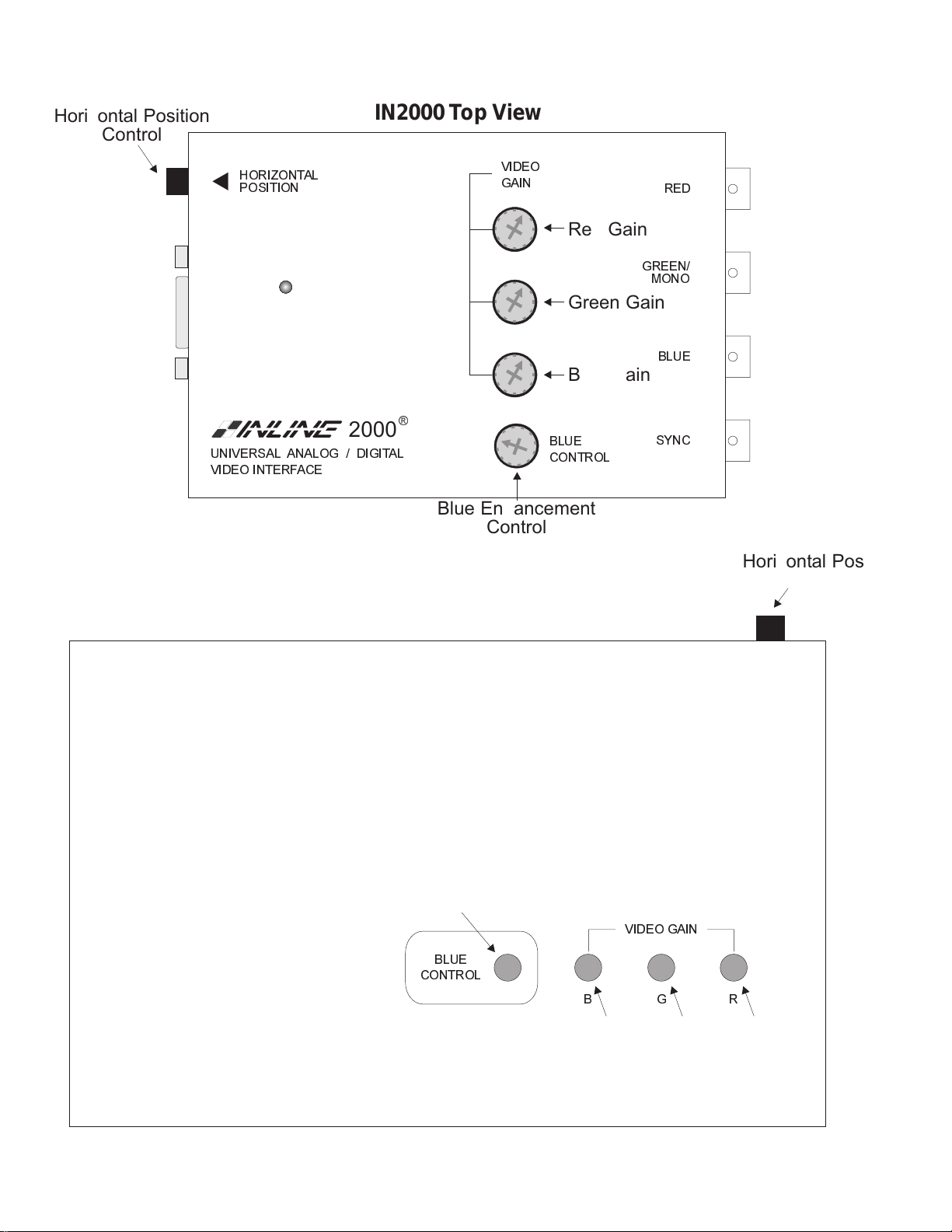
Horizontal Position
Control
IN2000 Top View
HORIZONTAL
POSITION
2000
UNIVERSAL ANALOG / DIGITAL
VIDEO INTERFACE
VIDEO
GAIN
®
Blue Enhancement
Control
Red Gain
Green Gain
Blue Gain
BLUE
CONTROL
RED
GREEN/
MONO
BLUE
SYNC
Horizontal Position
Control
IN2001 Top View
Blue Enhancement
Control
BLUE
CONTROL
B
VIDEO GAIN
Blue
Gain
GR
Green
Gain
Red
Gain
Page 10

8
INTERNAL CONTROLS
The IN2000 and IN2001 have been designed with several controls which may be used by qualified
technicians to adjust specialized signal parameters. These controls, consisting of 10 dip switches and one
adjustment pot, are infrequently used and do not require adjustment for normal daily operation. For
convenience, the IN2001 has been designed with two access slots in the bottom of the unit so the case
does not need to be opened to change the dip switches and adjustment pot. To access these controls on
the IN2000 follow the procedure listed below.
CAUTION: Any adjustment of internal controls on the IN2000 must only be carried out by qualified
technicians. The interface case must be opened to adjust these controls and extreme care must be
taken to avoid static shock to the internal components and/or damage to the pins which connect the
top and bottom circuit boards.
The following procedure may be used to access the IN2000 internal controls.
1. Remove power from the IN2000.
2. Remove the screw on the bottom of the unit and lift the top cover off. The top cover must be
lifted straight up, remaining absolutely parallel to the bottom half of the interface in order to
avoid bending the pins on the pin blocks.
3. Locate the desired dip switches or control pot and gently adjust as required using a small plastic
"tweeker" tool. See Pages 9 & 10 for details on these controls.
4. Replace the top cover. The interface end panels fit into slots in the top case and will act as a
guide, insuring that the pins and sockets on the top and bottom boards line up properly. Once the
two halves have been rejoined, tighten the case screw.
The drawing below diagrams the positions of the dip switches and internal control pot on the IN2000.
IN2000 Internal View - Bottom Board
IN2000 / IN2001 OPERATION MANUAL - RE V. 2.1 12/11/99 ©1996-1997 - INLINE, INC.
Page 11
Horizontal Blanking Control (TTL Only)
The Horizontal Blanking Control functions only with TTL digital input signals. This control (location
shown on Page 8) will not need to be adjusted on a regular basis. The following image symptoms may
indicate that the control is misadjusted: missing background colors, horizontal dark bars across the
screen, or missing foreground colors. Before adjusting the Horizontal Blanking Control, first check to
make sure that the external Horizontal Position Control (Page 6) is not causing any image problems. The
following procedure is recommended for adjusting the Horizontal Blanking Control:
1. IN2000 - Disconnect power and open the case.
IN2001 - Leave power on during adjustment. Turn unit over to access the dip switches
and Horizontal Blanking Control pot located on the bottom of the unit.
2. Activate the Blanking Control Pot by turning Dip Switch #10 to ON.
3. Adjust the control pot until the image quality improves and all the left hand edge of the
screen is displayed properly without being cut off.
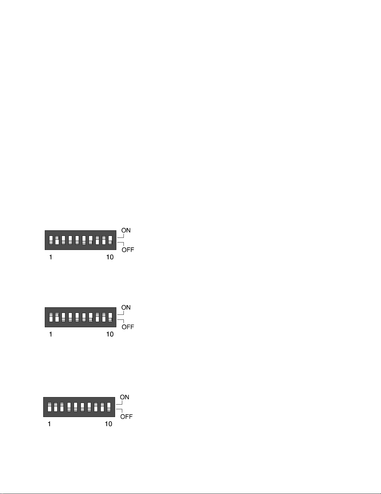
DIP SWITCH SETTINGS
Most installations will not require any changes to the dip switch settings, and the IN2000 / IN2001 will
generally be operated with the factory default settings. The Factory Default setting and specialized dip
switch settings are indicated below.
9
Factory Default Settings
Dip Switches ON: 2, 8 & 9
Signal Format: Red / Green / Blue / Composite Sync
Horizontal Position Control: Active
Blanking Control: Disabled
Sync on Green Output
Turn Dip Switch #1 to ON.
Dip Switches ON: 1, 2, 8 & 9
Signal Format: Red / Green with Composite Sync /
Blue
Monochrome Output
Turn Dip Switches #1 and #3 to ON. This combines the red, green, and blue video into composite
monochrome. The monochrome signal is output on the GREEN connector.
Dip Switches ON: 1, 2, 3, 8 & 9
Signal Format: Composite Monochrome
©1996-1997 - INLINE, INC. IN2000 / IN2001 OPERATION MANUAL - REV. 2.1 12/11/99
Page 12

10
Disable Horizontal Position Control
Turning Dip Switch #6 to ON disables the Horizontal Position Control. This setting should only be used
with Composite Sync or Sync on Green input signals. If Switch #6 is set to ON when using input signals
with separate Horizontal and Vertical syncs, the unit will not output any sync signal, causing the video
projector or data monitor attached to the IN2000 / IN2001 output to loose sync and stop displaying an
image.
Dip Switches ON: 2, 6, 8 & 9
Enable Blanking Control
Turning on Dip Switch #10 enables the Blanking Control pot. This pot adjusts the video signal left
blanking (TTL signals only) to ensure a clamp to black. For more information see Pages 8 & 9.
Dip Switches ON: 2, 8, 9 & 10
IN2001 INTERNAL FUSES
The IN2001 contains two internal fuses. If power is applied to the unit and the front LED doesn’t light,
one of the internal fuses may need to be replaced.
1. Remove power from the unit.
2. Loosen the two case screws on the bottom of the
unit.
3. Turn the unit back over (top facing up) and lift
off the top half of the IN2001 case. Capacitors C13
and C14 store an electrical charge even when the
unit is powered down. Take care not to touch
these components.
4. Locate the fuses (L1 & L2) and replace with new
250 mA / 250V fuses as required.
5. Replace the top case and tighten the two bottom
case screws.
IN2000 / IN2001 OPERATION MANUAL - RE V. 2.1 12/11/99 ©1996-1997 - INLINE, INC.
Page 13

IN5100 SERIES MONITOR LOOP CABLES - PARTIAL LISTING
Computer / Graphics Card Cable Model Connector
IBM PC AND COMPATIBLES
VGA / S-VGA / XGA / XGAII IN5101A 15 Pin HD
CGA / EGA IN5106T 9 Pin D
MDA / Hercules IN5105T 9 Pin D
APPLE
MACII / Quadra IN5161A 15 Pin D
MAC / MAC+ IN5107T Internal Harness
MAC SE IN5111T Internal Harness
Apple IIE IN5122T 9 Pin D
COMMODORE
Amiga 500 / 1000 / 2000 / 3000 / 4000 IN5147A 23 Pin D
WORKSTATIONS & TERMINALS
Sun Sparc Station IN5160A 13W3
Sun Monochrome IN5126A 9 Pin D
Silicon Graphics Iris Indigo IN5175A 13W3
NeXT Color IN5175A 13W3
NeXT Monochrome IN5137A 19 Pin D
IBM 3192 IN5127A 25 Pin D
NCD 17C IN5173A 26 Pin HD
DEC VT420 Kit IN5174A Internal Harness
1 - BNC - Monochrome IN5132A BNC
4 - BNC - RGBS or RGsB IN5129A BNC
5 - BNC - RGBHV or RGsB IN5133A BNC
11
IN2000 / IN2001 Input Pin Configuration - 15 Pin HD Female Connector
Pin 1 Red Video (Analog / TTL determined by Pins 14 & 15)
Pin 2 Green Video (Analog / TTL determined by Pins 14 & 15)
Pin 3 Blue Video (Analog / TTL determined by Pins 14 & 15)
Pin 4 Ground
Pin 5 Ground
Pin 6 Red Secondary (TTL only)
Pin 7 Green Secondary (TTL only)
Pin 8 Blue Secondary (TTL only)
Pin 9 *Vertical Sync Input
Pin 10 *Horizontal Sync Input
Pin 11 Reserved (Do not connect anything to this Pin!)
Pin 12 Ground
Pin 13 Invert Video (TTL Video Signals Only: Ground - Normal, Open - Inverted)
Pin 14 Analog / Digital Select (Open - Digital, Ground - Analog)
Pin 15 Analog / Digital Select (Open - Digital, Ground - Analog)
*Short Pins 9 & 10 together for Composite Sync input
©1996-1997 - INLINE, INC. IN2000 / IN2001 OPERATION MANUAL - REV. 2.1 12/11/99
Page 14

12
INTERFACING TO COMPUTERS WITH BNC OUTPUTS
The IN5129A, IN5132A, and IN5133A are special input cables designed for use with workstations and
terminals which have BNC video outputs. The chart below describes the input signal compatibility for
each of these cables:
Cable / Description Monochrome
RGsB RGBS RGBH&V
IN5129A 4 - BNCs X X
IN5132A 1 - BNC X
IN5133A 5 - BNCs X X
Installation Procedure - IN5129A / IN5133A
The video signal input to the IN2000 / IN2001 must be terminated into 75 ohms for proper image
display. In order to achieve this termination the following installation procedure should be followed:
1. Attach a BNC "T" (1 male, 2 female) to each BNC
output connector on the computer.
2. Connect the IN5129A or IN5133A cable to one
side of the "T" connectors.
3. Connect the local monitor to the other side of the "T"
connectors. If no local monitor is present, use a 75 ohm
Male BNC termination plug on the Red, Green, and
Blue connectors (TTL sync signals do not require a 75
Ohm terminator).
Installation Procedure - IN5132A
The IN5132A should be connected directly to the computer’s monochrome composite video output. This
cable includes an internal 75 ohm termination so the signal should not be split off to a local monitor
before feeding it into the IN5132A or a double termination will result. If a local monitor is required, use
one of the following methods to split the signal:
Looping Method - If the local monitor has a "Loop Out" connector, connect the monitor
directly to the computer video output. Turn the Loop Out termination switch to "75 ohm
termination OFF" and connect the IN5132A to the monitor’s Loop Out connector.
Distribution Amplifier - use a high resolution distribution amplifier such as the IN2055 to
split the signal between the local monitor and the IN5132A / IN2000.
IN2000 / IN2001 OPERATION MANUAL - RE V. 2.1 12/11/99 ©1996-1997 - INLINE, INC.
Page 15
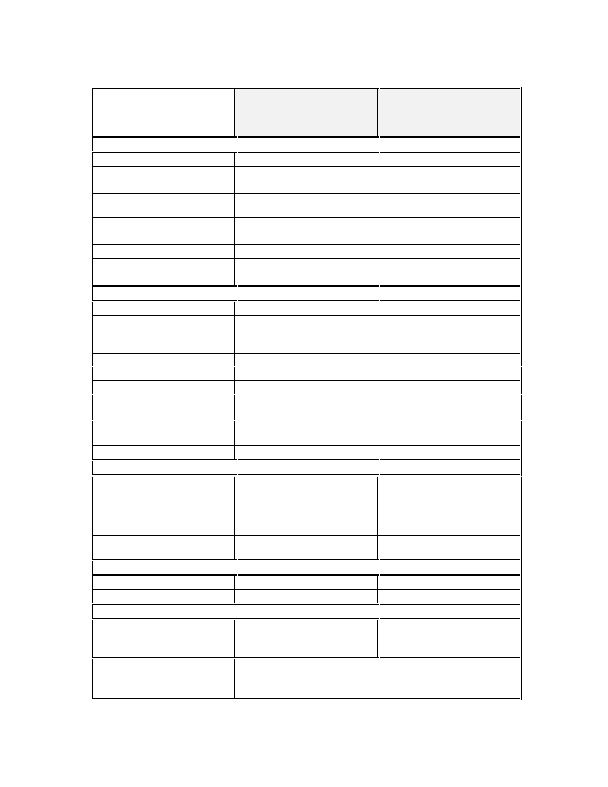
SPECIFICATIONS
13
Input
Connector type
RGB Video Signals
Input Impedance
Maximum Input Voltage
Sync Signals
Input Impedance
Maximum Input Voltage
Horizontal Scan Range
Vertical Scan Range
Output
Connector Type
Output Signal Formats
RGB Signals
Bandwidth
Rise and Fall Times
Gain
Sync Signal
Horizontal Pulse Width
Vertical Pulse Width
Controls
External
Internal
Dimensions
Size
Shipping Weight
Power
Power Supply
Consumption
Approvals
IN2000
Universal Computer
Universal Computer
Video Interface
15 Pin HD Female - Proprietary Pin-Outs
Analog / TTL Digital / ECL Digital
10 Kilo Ohms
Analog: +- 6V p-p
Digital: 5V DC / AC
Analog or Digital
1 Mega Ohms
+- 6V p-p
15.0 KHz - 145.0 KHz
30 Hz - 180 Hz
4 BNC Female connectors - Red / Green / Blue / Sync
RGBS (Default), RGsB,
Monochrome and separate sync, Composite Monochrome
Analog Video, 75 ohm impedance
100 MHz @ -3 dB
4.0 nano sec onds
Adjustable from 0.8 - 1.2
Sync output has AGC, 4V p-p unterminated
and 2V p-p terminated into 75 ohms
2.5 µS @ 15.0 to 36.0 KHz
1.2 µS @ 37.0 to 145.0 KHz
180 - 200 µS
RGB Gain
Blue Enhancement
Horizontal Position Control
Dip Switches
Horizontal Blanking Control
1.1" H x 4.8" W x 3.27" D 2" H x 6.75" W x 4.33" D
3 lb. 4 lb.
External AC to DC Power
Transformer, 12V 500 mA
3 Watts 3 Watts
UL1950, CAN/CSA-22.2 No.950, Third Edition
CE: EN55022 (1987), EN50081-1 (1991),
EN50082-1 (1992 and 1994), EN0950-92
Horizontal Position Control
Horizontal Blanking Control
Internal Transformer - Factory
set at 110V or 220V AC
IN2001
Video Interface
RGB Gain
Blue Enhancement
Dip Switches
None
©1996-1997 - INLINE, INC. IN2000 / IN2001 OPERATION MANUAL - REV. 2.1 12/11/99
Page 16

14
Parts and Accessories Included
IN2000
Adjustment Tool
12V 500 mA Power Supply
Operations Manual
IN2001
Adjustment Tool
AC Power Cable (US only)
Operations Manual
Optional Accessories
IN5100 Series Input Cables See Page 11 for a partial listing of available input cables. Fo r a
completelisting of IN5100 Series input cables see the current
INLINE Product Catalog.
IN7000 Series RGBS Cable 4 - BNC Cable available in a variety of lengths from 6’ to 100’
IN7100 Series RGBS Cable 4 - BNC High Resolution Cable, available in lengths from 6’ to 100’
IN7600 Series RGBS Cable 4 - BNC High Resolution Heavy Duty Cable, lengths from 6’ to 100’
The RGBS cables above are available in longer lengths by custom order and may also be purchased in bulk
quantities along with BNC connectors and crimp tools.
TROUBLESHOOTING
The display device connected to the IN2000 RGBS output has a bad/scrambled image.
Solution 1: Verify that the correct IN5100 Series input cable is being used.
Solution 2: The display device connected to the output of the interface may not be compatible with the
computer output. CGA and EGA signals vary from 15.75 to 24 KHz. VGA runs at
31.5 KHz, but SVGA can be as high as 48 - 58 KHz with newer modes such as 1600 x 1200
running at 79 KHz! MACII/Quadra computers sense which monitor is connected and
configure themselves accordingly, with horizontal scan rates ranging from 24.48 to 68.9
KHz.
Solution 3: Check the dip switch settings to make sure the unit is putting out a sync format that the
display device can use. For most applications the default dip switch settings (see Page 9)
will work best.
Solution 4: The RGBS cable may have a bad sync line. Try running the sync through another cable.
The output image is very dark.
Solution: The horizontal position control may be set off to an extreme position or may be interacting
poorly with the horizontal position control on the display device. Follow the horizontal
position adjustment procedure listed on Page 6.
The output image is missing a color.
Solution: Possibly the RGBS cable is bad. Try switching connections on the output to verify that the
bad color’s cable is OK (Example: If there is no red, try running the green output through
the red cable and see if green is displayed or not.)
IN2000 / IN2001 OPERATION MANUAL - RE V. 2.1 12/11/99 ©1996-1997 - INLINE, INC.
Page 17

The output image is very bright and overdriven looking with poor contrast.
Solution 1: The loop through cable is probably being used without a local monitor and the signal is
therefore unterminated. Use either a local monitor or a termination plug at the monitor loopthrough connector on the IN5100 Series cable. If this is not the problem try #2.
Solution 2: Verify the gain settings on the IN2000 / IN2001 RGB gain pots. If they are set to a very
high gain level, reduce the gain as required.
Solution 3: Check the contrast and brightness settings on the display device. Many CRT type display
devices look best with the contrast set toward the upper end of the adjustment range (75 95%) and the brightness set towards the middle of the adjustment range (40 - 60%).
The output image is ghosting.
Solution: The IN5100 Series cables are designed to plug directly into the computer’s graphic card and
a short (6 to 12 ft) monitor cable attached to the loop through output. An extension cable on
the input or a very long monitor cable may cause this problem. Do not attempt to extend the
length of the IN5100 Series monitor loop cable.
When using the IN2000 and an IN5101A with a VGA signal, the image from the RGBS
output is violet with a very low green signal.
Solution: The local monitor may be monochrome. If it is a monochrome monitor, the IN9030 mono
adapter must be used - the output of the IN2000 will be monochrome.
15
The output image from the IN2000/2001 has horizontal black bars throughout the image
when interfacing to TTL video signals (IN5100 cables ending with "T").
Solution: The Horizontal Blanking Control may need adjustment. First check the Horizontal Position
Control to ensure it is not causing the problem. If the problem persists, adjust the Horizontal
Blanking Control according to the procedure on Pages 8 & 9.
The output image is too green.
Solution 1: The dip switches may be set for Sync on Green output. Try changing the dip switches to
factory default settings (see Page 9) so the unit outputs an RGBS signal.
Solution 2: Some MACII and Quadra computers output an RGsBS signal. If an IN5161A cable is used
with the IN2000 / IN2001, the interface does not strip the sync off of the green, and the
resulting output signal is actually RGsBS. The problem can be solved by disconnecting the
composite sync signal from the display device, forcing the display to operate in Sync on
Green mode. If the display absolutely must have an RGBS signal, then an IN5104A cable
should be used. The IN5104A will force the IN2000 to strip the sync off of the green and
output a true RGBS signal.
The output image is doubled, with two images displayed side-by-side.
Solution: The display device may not be compatible with the horizontal scan rate of the computer.
This problem often occurs when a 31.5 KHz VGA signal is sent into an RGB monitor which
is only compatible with signals at 15.75 KHz.
If problems persist, call INLINE Technical Services at (800) 882-7117 for further assistance.
©1996-1997 - INLINE, INC. IN2000 / IN2001 OPERATION MANUAL - REV. 2.1 12/11/99
Page 18

16
WARRANTY
♦
INLINE warrants the equipment it manufactures to be free from defects in materials and
workmanship.
♦
If equipment fails because of such defects and INLINE is notified within two (2) years from the
date of shipment, INLINE will, at its option, repair or replace the equipment at its plant,
provided that the equipment has not been subjected to mechanical, electrical, or other abuse or
modifications.
♦
Equipment that fails under conditions other than those covered will be repaired at the current
price of parts and labor in effect at the time of repair. Such repairs are warranted for ninety (90)
days from the day of re-shipment to the Buyer.
♦
This warranty is in lieu of all other warranties expressed or implied, including without
limitation, any implied warranty or merchantibility or fitness for any particular purpose,
all of which are expressly disclaimed.
The information in this manual has been carefully checked and is believed to be accurate. However,
Inline, Inc. assumes no responsibility for any inaccuracies that may be contained in this manual. In no even t will
Inline, Inc. be liable for direct, indirect, special, incidental, or consequential damages resulting from any defect
or omission in this manual, even if advised of the possibility of such damages. The technical information
contained herein regarding IN2000 / IN2001 features and specifications is subject to change without notice.
IBM is a registered trademark of International Business Machines. Apple, MAC, Quadra and Centris, are
registered trademarks of Apple Computers, Inc. Iris Indigo is a registered trademark of Silicon Graphics. Sun
Sparc Station is a registered trademark of Sun Microsystems, Inc. All other trademarks and registered
trademarks are the property of their respective companies.
All Rights Reserved © Copyright 1995-1997
INLINE, INC. ♦ 22860 SAVI RANCH PARKWAY ♦ YORBA LINDA, CA 92887
©
(800) 882-7117 ♦ (714) 921-4100 ♦ FAX (714) 921-4160
♦ www.inlineinc.com
IN2000 / IN2001 OPERATION MANUAL - RE V. 2.1 12/11/99 ©1996-1997 - INLINE, INC.
 Loading...