

Page 1
network-electronics.com
VikinX Modular
Analog Audio Router
Rev. 8
VikinX User Manual
A3232M/A6464M/A128128M/A3232S/A6464S
Page 2
Modular Analog Audio Router Rev. 8
Network Electronics AS
Nordre Kullerød 1
P.O. Box 1020
Sandefjord, Norway
Phone: +47 33 48 99 99
Fax: +47 33 48 99 98
E-mail:
mailto:[email protected]
http://www.network-electronics.com/
Service Phone: +47 90 60 99 99
Revision history
Current revision of this document is the uppermost in the table below.
Revision Replaces Date Change description
8 7 2008-06-13
Expanded description of how to configure
Mono/Stereo router(s), Chapter
3.2.1.
7 6 2007-11-06
Added description of how to configure
Mono/Stereo router(s), Chapter
3.2.1.
6 5 2007-10-26 New front page.
5 4 2007-03-29
Added Materials Declaration and EFUP; updated
EC Declaration of Conformity.
4 3 Updated product names and GYDA section
3 2 09/02/06 Removed protocol and configuration details.
2 1 28/09/05
Corrected RS-422 pinout description in Chapter
4.1.
1 0 22/04/05
Corrected router size options and combined 9RU
and 5RU frames.
0 - 11/03/05 Initial Revision, based on VD/HD128M manual.
2
Page 3

Modular Analog Audio Router Rev. 8
Contents
Revision history............................................................................... 2
General environmental requirements for Network Electronics
equipment ..................................................................................... 5
Product Warranty ........................................................................... 6
Important notes regarding Software in the VikinX Modular router
family range ................................................................................... 7
1 Product overview......................................................................... 8
1.1 Product versions ..........................................................................................8
2 Specifications .............................................................................. 9
2.1 Mechanics ...................................................................................................9
2.2 Power Supply ..............................................................................................9
2.3 Control........................................................................................................9
2.4 Signal specifications...................................................................................10
2.5 Rear view...................................................................................................11
3 Modules inside the Modular Analog Audio Router ..................... 13
3.1 How to access the modules .......................................................................13
3.2 How to configure the router and modules.................................................13
3.2.1 How to configure Mono/Stereo routers 14
3.3 Power Supply module................................................................................14
3.3.1 Module insertion 15
3.3.2 Module removal 15
3.3.3 How to connect power to the Modular Analog Audio Router 15
3.3.4 Status LEDs and Relay contacts 16
3.4 System Controller – Syscon-SM .................................................................16
3.4.1 Card insertion 17
3.4.2 Card removal 17
3.4.3 Status LEDs and Reset button 18
3.4.4 CF-card and battery 19
3.5 GYDA-VX...................................................................................................20
3.5.1 Card insertion 20
3.5.2 Card removal 20
3.5.3 Status LEDs and Reset button 21
3.5.4 CF-card and battery 21
3.6 X-point module .........................................................................................21
3.6.1 Card insertion 21
3.6.2 Card removal 21
3.6.3 Status LEDs 22
3.6.4 Service switches and Reset button 23
3.6.5 Gain compensation switches 23
3
Page 4

Modular Analog Audio Router Rev. 8
4 Router communication .............................................................. 26
4.1 Serial connection.......................................................................................26
4.2 Maximum cable length (RS-232) ...............................................................27
4.3 Ethernet connection ..................................................................................27
5 Connecting signal cables to the router ...................................... 28
5.1 Unbalanced signals on the Modular Analog Audio Router .........................28
6 Before calling Network Support ................................................. 29
7 Serial number overview ............................................................. 30
Notes ........................................................................................... 31
Materials Declaration and EFUP .................................................... 32
Materials declaration .......................................................................................32
Environmentally Friendly Use Period (EFUP).....................................................32
Recycling information......................................................................................33
EC Declaration of Conformity ....................................................... 34
4
Page 5

Modular Analog Audio Router Rev. 8
General environmental requirements for Network Electronics
equipment
1. The equipment will meet the guaranteed performance specification under the
following environmental conditions:
- Operating room temperature range: 0°C to 45°C
- Operating relative humidity range: < 95% (non-condensing)
2. The equipment will operate without damage under the following environmental
conditions:
- Temperature range: -10°C to 55°C
- Relative humidity range: < 95% (non-condensing)
5
Page 6

Modular Analog Audio Router Rev. 8
Product Warranty
The warranty terms and conditions for the Modular Analog Audio Router
follow the General Sales Conditions by Network Electronics AS. These
conditions are available on the company web site of Network Electronics AS:
www.network-electronics.com
6
Page 7

Modular Analog Audio Router Rev. 8
Important notes regarding Software in the VikinX Modular router family
range
This product utilizes software components that are licensed with open source
licenses. The source code for these components, and our modifications are
available from:
http://labs.network-electronics.com/open-source/
You may also send Network Electronics a recordable CD and a self-addressed
envelope, and we will burn the contents of
http://labs.network-
electronics.com/open-source/ to your CD and send it back to you.
This offer is valid for 3 years after purchase of this product.
7
Page 8

Modular Analog Audio Router Rev. 8
1 Product overview
The Modular Analog Audio Router is part of the VikinX Modular product
range, offering up to 128x128 X-points for Analog Stereo Audio signals.
This top of the line router provides a very compact frame, fully hot-swappable
architecture, built-in dual redundant power supply and fully redundant
controller functions.
Starting with the size of 64x64 mono audio, or 32x32 stereo audio crosspoints, the router can be expanded under operation with 64x64 increments.
Advanced control features like TCP/IP interface and SNMP agent, as well as
comprehensive surveillance of the router’s vital parameters are possible via the
well known GYDA-VX controller.
As for our well known VikinX compact router series low power consumption
has been important.
VikinX Modular provides a fully hot-swappable architecture, meaning that all
components are front loaded without any active components on the rear
panel.
VikinX Modular provides all important 3
rd
party control interfaces allowing the
control of our routers through 3
rd
party management software. On top of that
the Network Electronics’ THOR management package allows control of the
most common 3
rd
party routers. This enables you to utilize existing routers and
management systems from other manufacturers and still draw the advantages
of implementing VikinX Modular in your routing application.
1.1 Product versions
The following versions of the VikinX Modular Stereo Analog Audio Router are
available:
Analog Stereo Audio router - 9RU:
A3232M VikinX Modular router for Analog Stereo Audio, 9RU,
equipped 32x32, expandable up to 128x128.
A6464M As above, but equipped 64x64.
A128128M As above, but fully equipped 128x128.
Analog Stereo Audio router - 5RU:
A3232S VikinX Modular router for Analog Stereo Audio, 5RU,
equipped 32x32, expandable up to 64x64.
A6464S As above, but fully equipped 64x64.
8
Page 9

Modular Analog Audio Router Rev. 8
2 Specifications
2.1 Mechanics
Dimensions: HxWxD = 396x483x340mm, (19”, 9RU), or
HxWxD = 220x483x340mm, (19”, 5RU).
Backplane card: 128x128 Analog Stereo Audio (9RU), or
64x64 Analog Stereo Audio (5RU).
X-point Modules: 64x64 mono, 32x32 stereo audio module cards.
System Controller: 1 Syscon card required, must be specified, 1 redundant card
is optional.
GYDA-VX: 2 GYDA-VX cards, both optional.
Safety/Emission standards: Compliant with CE EN55103-1 and 2, FCC part 15.
2.2 Power Supply
Built-in, redundant power supply. 1 module included, 1 (redundant) optional.
Backplane card: 2x AC-inlets.
Main internal voltage: 36 - 72VDC.
AC Supply voltage range: 90-130VAC / 180-254VAC, switchable, 50-60Hz, 300W.
AC Mains connector: IEC 320, separate input for each PSU module.
Alarms: Power failure alarm on relay contact closure, LED in front,
and Open Collector to GYDA-VX.
Alarms connector: RJ45.
Safety standards: Compliant with CE EN60950, UL-1950/CSA22.2.
2.3 Control
Standard Features:
Audio control: - Stereo audio
- Left-/Right channel controlled independently.
Serial ports:
Connector:
- RS-232/RS-422 for protocol conversion, to VikinX
compact control protocol, or to third party protocols.
(1x per Syscon card).
- RS-232/RS-422 for new router control protocol.
(1x per Syscon card).
DB9, female.
Ethernet ports:
Connector:
- 10/100BaseT Ethernet bus for external router control
with new protocol. (1x per Syscon card).
- 10/100BaseT Ethernet bus for GYDA-VX (1x per GYDAVX card).
RJ45.
Monitored parameters: - Module temperature.
- Internal module voltages.
Status surveillance: On each card with LED, and via system controller.
Configuration storage: Removable compact flash card.
9
Page 10

Modular Analog Audio Router Rev. 8
Synchronization handled
by Syscon-SM
1
:
Connector:
- Analog Black Burst, Looped. Both PAL and NTSC
supported.
- Tri-Level, Looped. For HD signal formats only.
BNC.
Optional Features:
Redundant control: Redundant Matrix Control using 2x Syscon.
TCP/IP: Web interface, with GYDA-VX.
SNMP agent: With GYDA-VX.
Event log: With GYDA-VX.
2.4 Signal specifications
Electrical signal inputs:
Type: Balanced.
Connector: DB25 female.
Impedance: > 10 kohm.
CMRR: > 60 dB.
Max. level: +23 dBu.
Electrical signal outputs:
Type: Balanced.
Connector: DB25 female.
Impedance: < 66 ohm.
CMRR: > 60 dB.
Max. level: +23 dBu.
Gain adj.: 1.0 dB (compensation for 600 ohm load).
Performance:
Frequency response: 20Hz-125kHz (-3dB)
20Hz-20kHz (± 0.3dB).
Adjacent crosstalk: > 100 dB, 20Hz-20kHz.
Click noise: < 50dBu.
THD+N: < 0.01%.
SNR: > 90dB ref. to 0dB 20Hz-20kHz.
1
Synchronisation of an Analog audio router is not necessary, but an available feature for users who intend
to switch this router synchronised to video, using video synchronisation signals.
10
Page 11
Modular Analog Audio Router Rev. 8
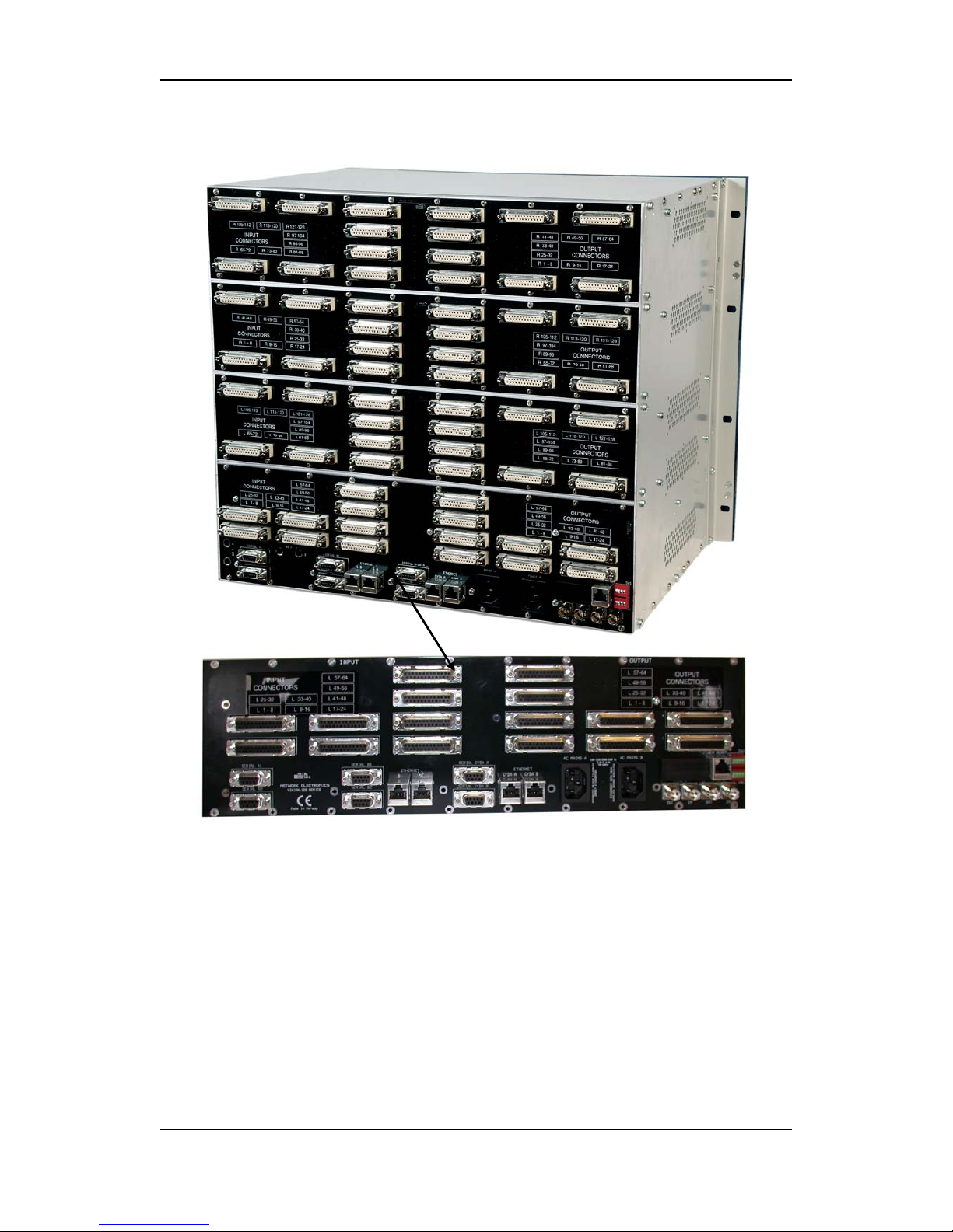
2.5 Rear view
2
The following service connectors can be found on the rear of the Modular
Analog Audio Router:
- AC Mains A: AC mains power supply.
- AC Mains B: AC mains power supply (if redundant PSU is installed).
- Serial A1 and A2: RS-232 or RS-422 for external control protocols.
- Serial B1 and B2: RS-232 or RS-422 for external control protocols (if
redundant Syscon is installed).
- Ethernet A: 10/100Base-T Ethernet bus for external router control.
- Ethernet B: 10/100Base-T Ethernet bus for external router control (if
redundant Syscon is installed).
- Serial GYDA A: RS-232 or RS-422 for external connection to GYDA-VX (if
GYDA-VX is installed).
2
The picture shows a 9RU frame. The 5RU misses the upper two connector boards.
11
Page 12

Modular Analog Audio Router Rev. 8
- Serial GYDA B: RS-232 or RS-422 for external connection to GYDA-VX (if
redundant GYDA-VX is installed).
- Ethernet GYDA A: 10/100Base-T Ethernet bus for external connection to
GYDA-VX (if GYDA-VX is installed).
- Ethernet GYDA B: 10/100Base-T Ethernet bus for external connection to
GYDA-VX (if redundant GYDA-VX is installed).
- VIT 1: Synchronization signal 1 (in/out). Black burst/composite/tri-level
sync reference input with passive loop-through for vertical interval
switching.
- VIT 2: Synchronization signal 2 (in/out). Black burst/composite/tri-level
sync reference input with passive loop-through for vertical interval
switching.
- Power Alarm: Power fail alarm relay contacts. Separate contact pair for
each PSU module that is installed. Contact closes on power failure. See
Chapter 2 for further description.
- SW 1: Configuration switch 1 (not in use).
- SW 2: Configuration switch 2 (not in use).
12
Page 13
Modular Analog Audio Router Rev. 8
3 Modules inside the Modular Analog Audio Router
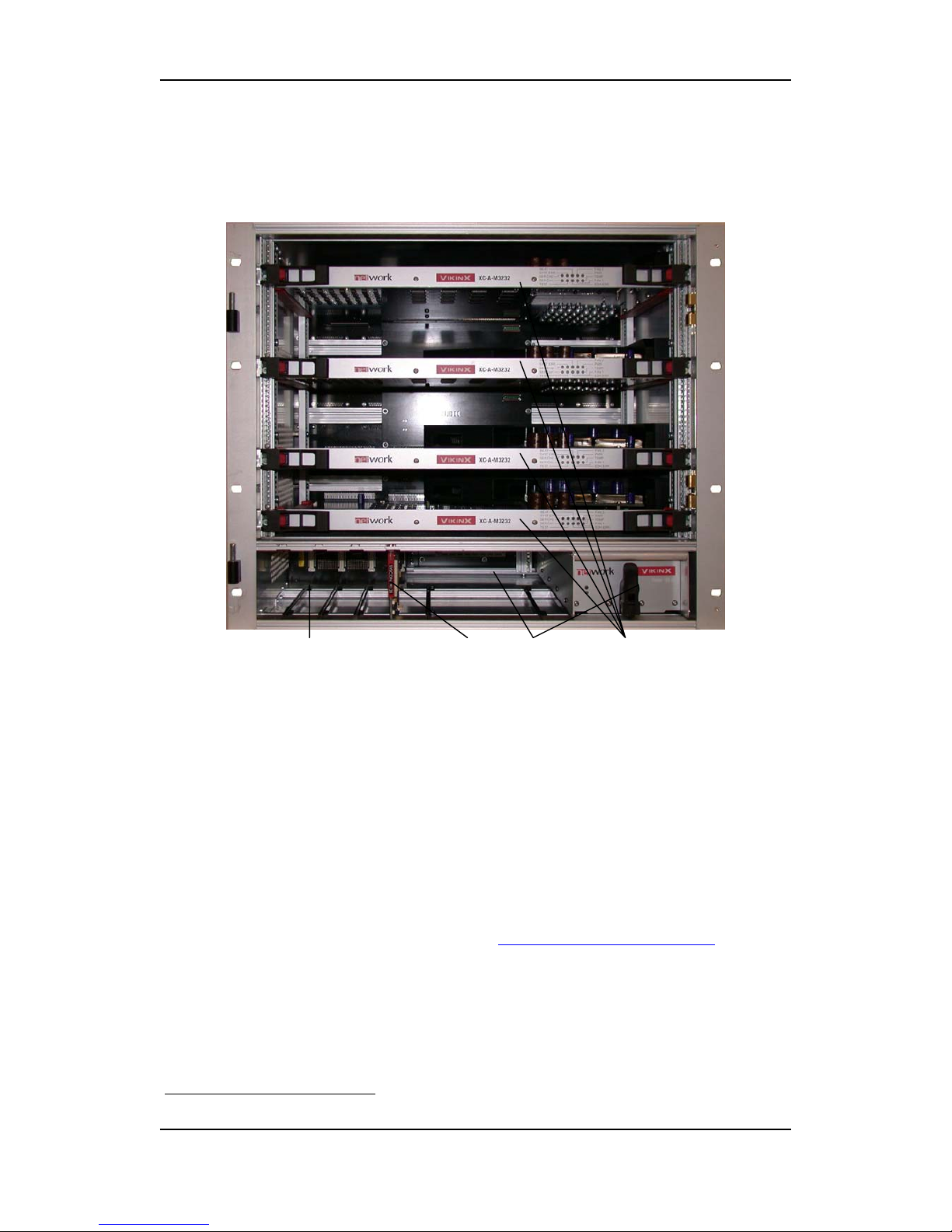
In order to get an overview of the parts that form the Modular Analog Audio
Router this chapter will highlight some of the main components.
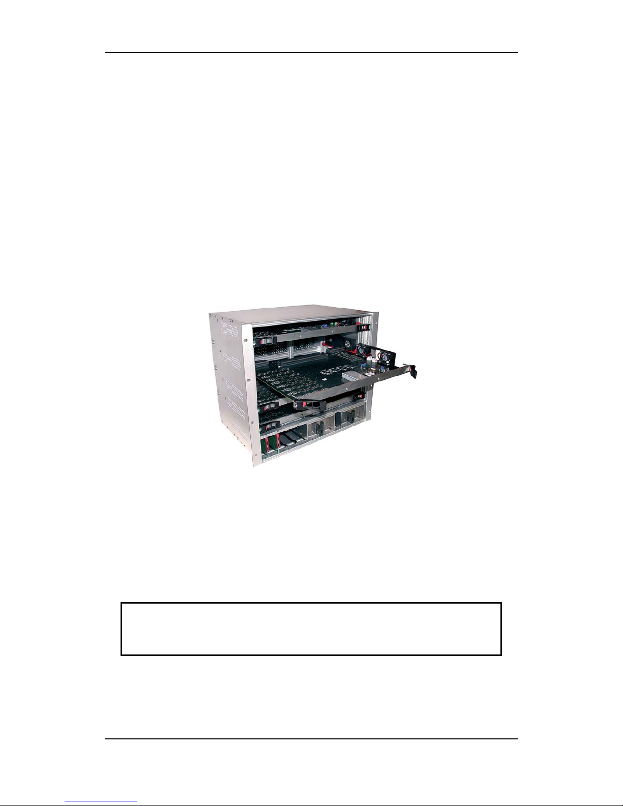
GYDA-VX (not shown in picture) Syscon Power Supplies Audio Modules
3
3.1 How to access the modules
All active modules are accessible through the front of the router frame. If
service or inspection is required, open the unit from the front. The door may
be removed for easy access to the modules.
An important feature of all the modules in the Modular Analog Audio Router
frame is that they are all hot-swappable. The user does not have to turn off
the power in order to remove/reinstall/replace a module with active
components inside the Modular Analog Audio Router.
3.2 How to configure the router and modules
Setting up and configuring the router and its modules are done with the
System Configurator software. The System Configurator is shipped with the
router, or could be downloaded from
www.network-electronics.com.
For further instructions on router configuration, please see the online
documentation in the System Configurator.
3
The picture shows a 9RU frame. The 5RU misses the upper two X-point Modules.
13
Page 14

Modular Analog Audio Router Rev. 8
3.2.1 How to configure Mono/Stereo routers
You may configure a Modular router as either 32x32/64x64/128x128 Stereo,
or 64x64/128x128 Mono, respectively. It is not possible to configure a
256x256 Mono from a 128x128 Stereo router.
In order to configure an A6464M (or A6464S) Mono router to an A3232M (or
A3232S) Stereo router, please follow this procedure:
1. Open the System Configurator;
2. Select the Syscon that belongs to the router you want to reconfigure;
3. Select Modular level setup;
4. Select Show details;
5. Select Add new;
6. Change the name under “Description” to “Left channel” on the first one
and to “Right channel” on the second one;
7. On “Left channel”, change the physical input to: “from 1 to 32” and
physical output to: “from 1 to 32”;
8. On “Right channel”, change the physical input to: “from 33 to 64” and
physical output to: “from 33 to 64”;
9. Select Apply;
10. Restart the router, and you have a 32x32 Stereo Analog Audio router,
where the left channel in connected to I/O#1-32 on the lower backplane
and the right channel is connected to I/O#33-64 on the same backplane.
In order to configure an A3232S Stereo router to an A6464S Mono router,
please follow this procedure:
1. Open the System Configurator;
2. Select the Syscon that belongs to the router you want to reconfigure;
3. Select Modular level setup;
4. Select Show details;
5. Select Add new;
6. Change the name under “Description” to e.g. “Mono channel” on the
new one;
7. On “Mono channel”, change the physical input to: “from 1 to 64” and
physical output to: “from 1 to 64”;
8. Select Apply;
9. Restart the router, and you have a 64x64 Mono Analog Audio router.
3.3 Power Supply module
Each Modular Analog Audio Router frame comes with either one or two
power supply modules. One power supply is standard, dual redundant power
supply is an option.
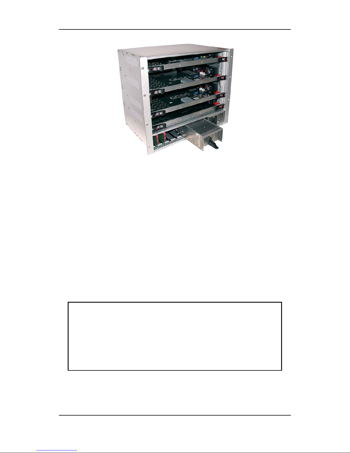
The first power supply module is inserted in the left slot (A), and the second is
inserted in the right slot (B). (The power module A is pulled out in the figure
below).
14
Page 15
Modular Analog Audio Router Rev. 8
3.3.1 Module insertion
In order to insert a power supply module one must insert the module via the
special plastic guide rails into its position. Once the module is inserted, fix the
module by lifting up the handle on the front and pushing it to the upright
position.
3.3.2 Module removal
In order to remove a power supply module, one must pull down the handle
on the front downwards to a horizontal position, and pull the module out
with the bar on top of the power module.
3.3.3 How to connect power to the Modular Analog Audio Router
There are two power connectors on the back of the frame. Both of these
connectors are for AC mains connection.
Use an IEC 320 connector to connect AC mains to the Modular Analog Audio
Router frame.
If the frame is equipped with a single power supply module, only one AC
mains connection is used. However, if the frame is equipped with dual,
Note:
There is a switch on the right hand side of the power supply module that
selects mains voltage. The mains voltage can be either 110VAC or 230VAC.
This switch must be set in the correct position, depending on the mains
voltage on the router’s site.
Failing to select correct AC mains voltage properly may damage the
Power Supply Unit.
15
Page 16
Modular Analog Audio Router Rev. 8
redundant power supply modules, both AC mains connectors must be used,
preferably from two different mains circuits.
3.3.4 Status LEDs and Relay contacts
There are 2 LEDs on the front of each power supply module, and they indicate
the following:
- The upper, RED LED should be normally OFF. If it is ON, there is a power
supply failure, indicating that the power supply module must be replaced.
- The lower, GREEN LED must be ON when mains power is connected. If this
LED is OFF, it means that there is no mains power supplying the frame.
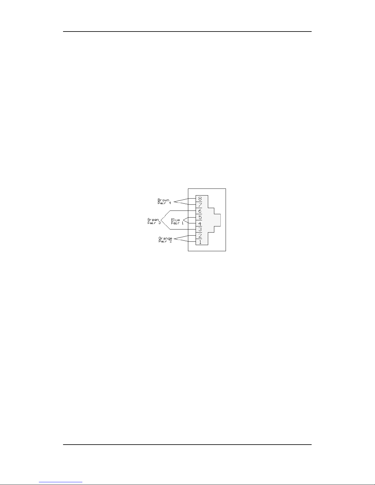
There are also two Power fail alarm relay contacts on the rear side of the
frame; see Chapter 1 for details. Each installed PSU module has a separate pair
of contacts. The relay contact is normally open, and the contact closes on
power failure.
- The PSU module A alarm is formed by contact between Pin 3 and Pin 6
(Green pair)
- The PSU module B alarm is formed by contact between Pin 1 and Pin 2
(Orange pair)
3.4 System Controller – Syscon-SM
Each VikinX Modular frame comes with either one or two system controller
cards, Syscon. One Syscon is necessary to control the router; dual redundant
Syscon is an option.
Syscon can be enabled for 3rd party control interfaces. Please contact your
Network representative for details.
Your Syscon card(s) may be inserted in any of the two slots (A) and (B).
All the configuration parameters, control parameters, etc. are stored in the
Compact Flash (CF) memory of the Syscon card. This provides a high grade of
security for the user, as he just needs to remove the CF card if the Syscon card
fails, and install this CF card on a new Syscon card. The router will not notice
the difference.
16
Page 17
Modular Analog Audio Router Rev. 8
3.4.1 Card insertion
The frame is equipped with plastic guide rails to align the Syscon cards into
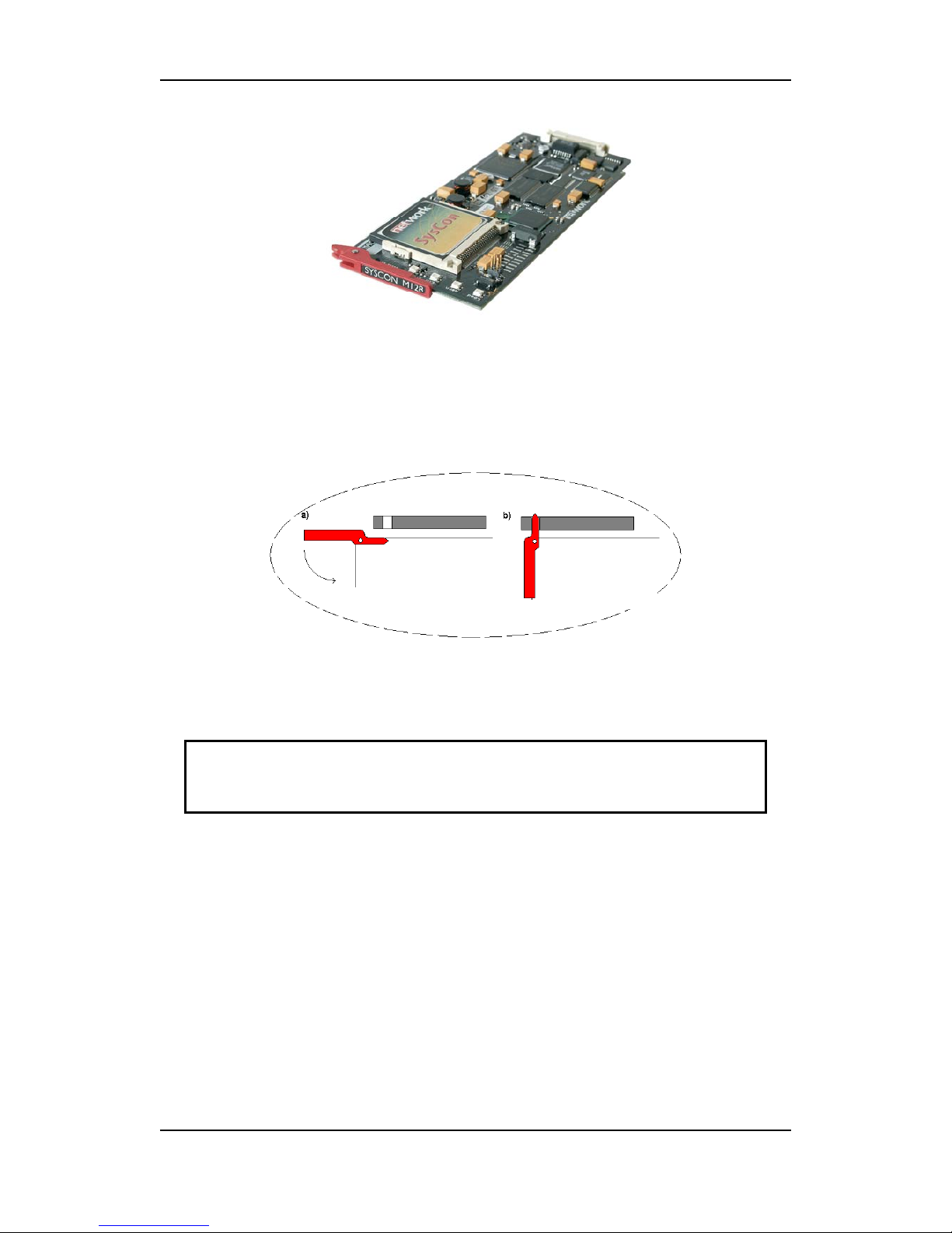
their respective positions. Slide the card into the plastic guide rails inside the
frame until the red handle is close to the frame front. A detailed description of
the last part of the insertion process is shown in the figure below.
On the top of the card tray, there is a hole above each module slot. When the
tip of the handle is just below this hole, start to push the handle downwards
as in the figure. The tip of the handle enters the hole and the card is locked
and proper contact ensured when the handle is in downright position.
Do not use excessive force; the card should enter easily –
proper insertion is almost effortless.
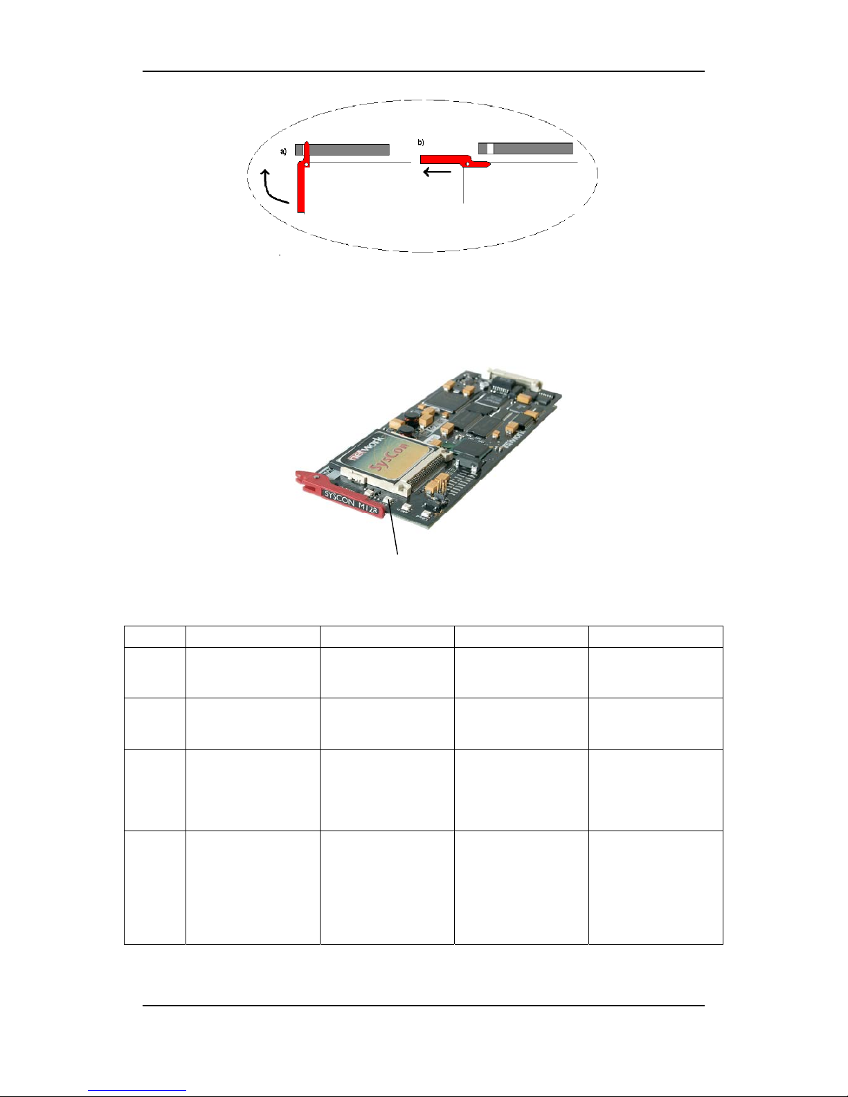
3.4.2 Card removal
To remove a module card from the sub-rack frame, release the card by
moving the red handle until it is in horizontal position, as shown in the figure
below. Then pull the card out of the sub-rack with the red handle.
17
Page 18
Modular Analog Audio Router Rev. 8
3.4.3 Status LEDs and Reset button
There are 4 LEDs on the front side of the Syscon card, and a reset button on
the rear side.
Status LEDs
The LEDs indicate the following:
Diode
Red LED Yellow LED Green LED
No light
Status
Card error. Not applicable. Overall status of the
card is OK
Card has no power, or
is not inserted
correctly.
Eth
Not applicable. Full duplex
connection.
Half duplex
connection.
No Ethernet link
established; check
cable.
Warn
Abnormal situation:
no functional error,
but a situation that
requires attention.
See also Chapter
6.
Not applicable. Normal situation. Not applicable.
Load
High load on the
μController.
May occur during
system start up and
software
reconfigurations / upgrades.
Medium load on the
μController.
Low or normal load
on the μController.
Not applicable.
18
Page 19
Modular Analog Audio Router Rev. 8
Reset button
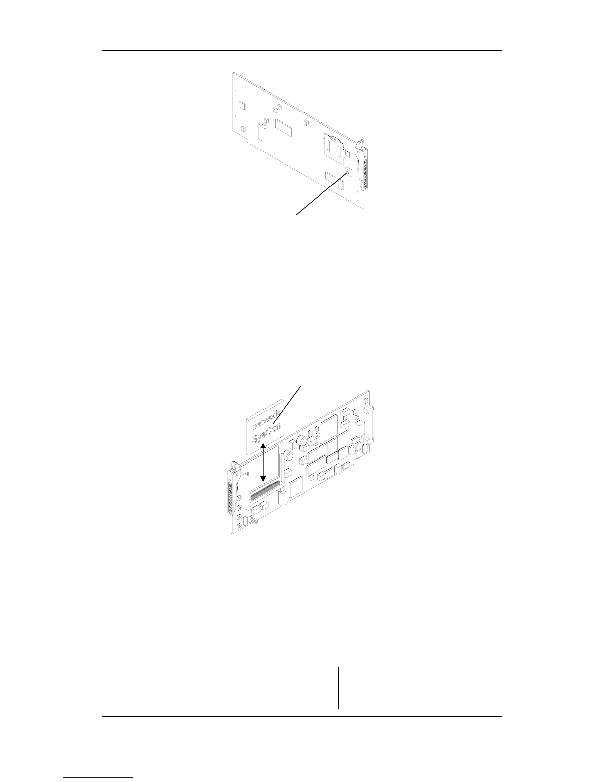
The reset button on the rear side is used to perform a hard reset of the card.
Do not perform a hard reset, unless the situation demands this. By performing
a hard reset, the user looses control of the router, and will not get control of
the router until approximately 20 seconds after releasing the reset button.
3.4.4 CF-card and battery
All the information regarding the router configuration, as well as information
regarding control panels that are connected to the router, is stored in the
Compact Flash card on the Syscon card.
If it is necessary to remove and/or insert a CF card, the following must be
done:
Compact Flash card
1. Remove the Syscon card from its slot, according to the description
earlier in this manual.
2. Slide the CF card out of its socket, and insert the new CF card into the
socket.
3. Insert the Syscon card into its slot, according to the description earlier
in this manual.
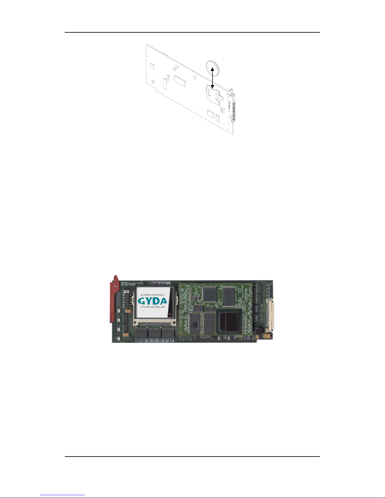
If it is necessary to remove and/or insert a battery, the following must be
done:
Battery
19
Page 20
Modular Analog Audio Router Rev. 8
1. Remove the Syscon card from its slot, according to the description
earlier in this manual.
2. Slide the battery out of its socket, and insert the new battery into the
socket.
3. Insert the Syscon card into its slot, according to the description earlier
in this manual.
3.5 GYDA-VX
The VikinX Modular frames can optionally be delivered with one or two
(redundant) GYDA-VX card(s). The GYDA-VX provides many useful and
requested features for STATUS MONITORING of the Modular Router.
The GYDA-VX provides the user with SNMP agent and TCP/IP Web interface,
allowing monitoring and control of the router from any site that has access to
an Internet browser. The GYDA-VX also provides a Log useful for engineering
purposes.
Your GYDA-VX card(s) may be inserted in any of the two dedicated GYDA
slots (A) and (B). See picture under 3.
3.5.1 Card insertion
The GYDA-VX card is inserted in the exact same way as the Syscon card. See
Chapter
3.4.1.
3.5.2 Card removal
The GYDA-VX card is removed in the exact same way as the Syscon card. See
Chapter
3.4.2.
20
Page 21
Modular Analog Audio Router Rev. 8
3.5.3 Status LEDs and Reset button
The meaning of the Status LEDs and the function of the Reset button on the
GYDA-VX card is exactly the same as on the Syscon card. See Chapter
3.4.3.
3.5.4 CF-card and battery
The Compact Flash (CF) card and battery are both inserted and/or removed in
the exact same way as on the Syscon card. See Chapter
3.4.4.
3.6 X-point module
Each VikinX Modular frame must be equipped with at least one X-point card,
in order to work as a router.
A maximum of four X-point cards can be inserted into the 9RU frame,
providing router sizes from 32x32 stereo audio, via 64x64 stereo audio, up to
128x128 stereo audio.
A maximum of two X-point cards can be inserted into the 5RU frame,
providing router sizes of either 32x32 stereo audio or 64x64 stereo audio. The
X-point cards are inserted according to the labeling on the rear side of the frame.
3.6.1 Card insertion
To insert an X-point card, slide the module along the plastic guide rails into its
position. On both sides of the card tray there is a hole next to each module
slot. Use the two red handles, which are located on the front of the module to
seat the module. When the tip of both handles is just next to these holes, start
to push the handles simultaneously inwards the card. The tip of the handles
enters the hole and the card is locked and proper contact ensured when you
hear a click from both handles.
Note that it may be necessary to press hard when inserting the X-point
card(s). Be sure to press the card(s) firmly into the frame, before locking the
handles.
3.6.2 Card removal
To remove an X-point card from the frame, release the card by pushing the
red knobs on each handle until each handle releases from its locked position.
Then pull both handles simultaneously, and pull the card out of the frame.
21
Page 22
Modular Analog Audio Router Rev. 8
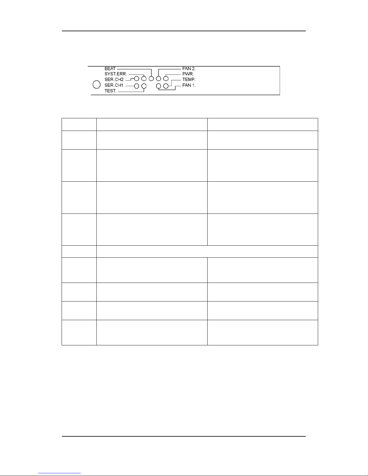
3.6.3 Status LEDs
There are 9 LEDs on the front of each Analog Audio X-point card:
They indicate the following:
Diode
Red LED Green LED
BEAT
Blinks when the µController is running
(heartbeat).
SYST.ERR
A fault is detected on the card.
The system controller lights, or turns off
this LED. This is used for simplifying the
identification of a module.
SER.CH2
Blinks each time the µController of the
X-point card answers a message from the
system controller on communication
channel 2.
SER.CH1
Blinks each time the µController of the
X-point card answers a message from the
system controller on communication
channel 1.
TEST
No special function; for internal testing purpose only.
FAN 2
Fan error, when the fan speed is outside
its normal range. FAN2 is the innermost
fan on the X-point card.
The fan speed of FAN2 is in its normal
range. FAN2 is the innermost fan on the
X-point card.
PWR
Any of the voltages on the card is outside
their legal range.
All internal voltages are OK.
TEMP
The temperature of the card is outside its
legal range.
The temperature of the card is OK.
FAN1
Fan error, when the fan speed is outside
its normal range. FAN1 is the outermost
fan on the X-point card.
The fan speed of the first fan is in its
normal range. FAN1 is the outermost fan
on the X-point card.
Note that all alarm ranges are configurable from the system controller.
22
Page 23
Modular Analog Audio Router Rev. 8
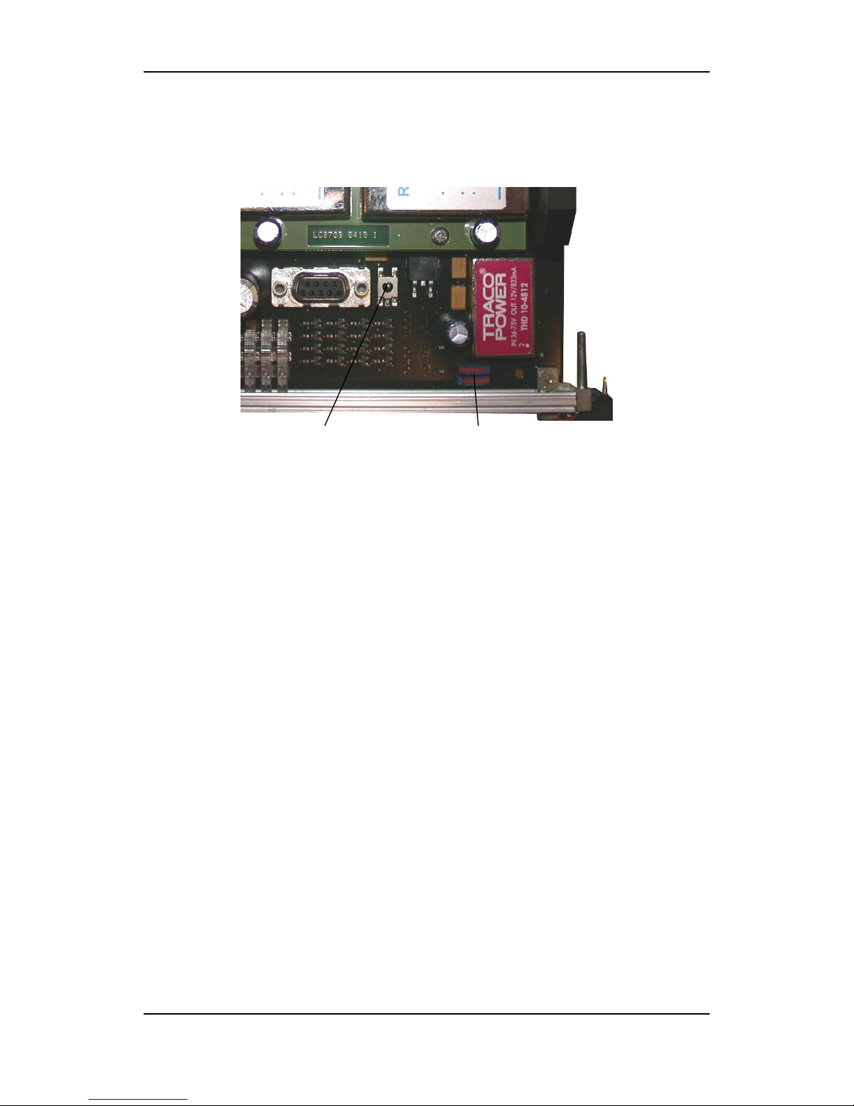
3.6.4 Service switches and Reset button
There are two slide-switches and one push-button switch on the card, as
shown in the figure below.
Reset button Service switches
The push-button switch is the RESET switch. When this button is pushed and
released, the μController of the X-point card resets and restarts its operation
with its default settings, or the settings stored in EEPROM.
The slide switch closest to the front of the X-point card (SW2): This switch
must always stay in the right position, as seen from the card front. The switch is
for factory use only.
The slide switch furthest from the front of the X-point card (SW4): This switch
must always be in the left position, as seen from the card front. The switch is for
factory use only.
3.6.5 Gain compensation switches
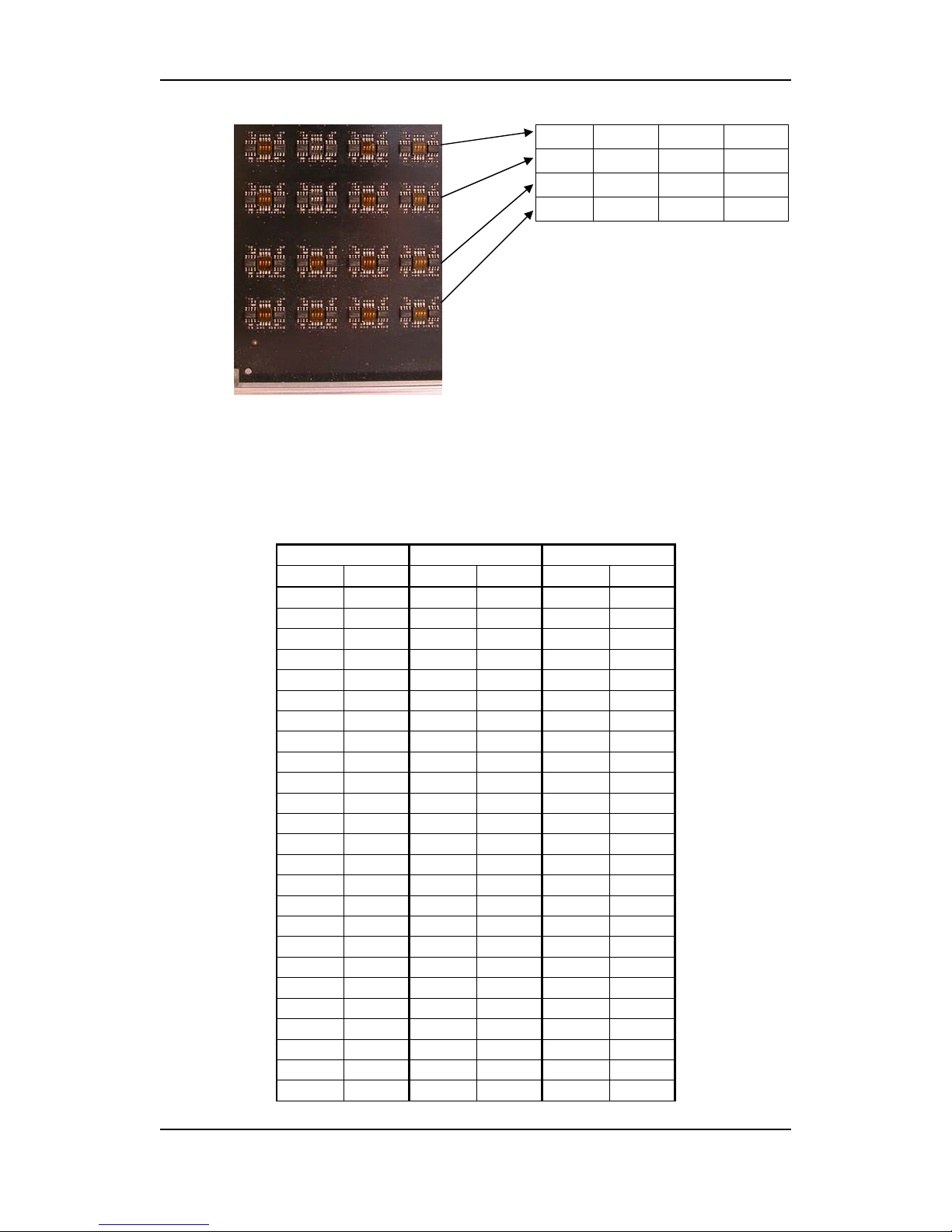
There are 64 Dipswitches (16 blocks with 4 switches each) on the left side of
the X-point card, as shown in the figure below. The switches are numbered as
shown in the table next to the figure (seen from the front of the card).
These switches are applied to set gain compensation when using 600 Ohms
load on respective outputs.
Set the Dipswitch to ON (direction towards the card front) in order to increase
the level of the associated router output, to compensate for a 600 Ohms load
on respective output.
Default setting is OFF (direction away from the card front).
23
Page 24
Modular Analog Audio Router Rev. 8
SW1 SW81 SW161 SW241
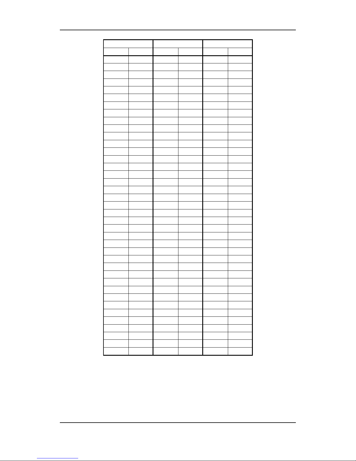
The rows and columns of the table below have the following meaning:
- Card positions are numbered from the lowest position in the frame (#1), to
the uppermost position in the frame (#4).
- Output # is the physical output from the router.
- Switch # are numbered as follows: Dipswitch #1 is the rightmost switch on
each block; switch #4 is the leftmost switch.
Card position: 1 Card position: 2 & 4 Card position: 3
Output # Switch # Output # Switch # Output # Switch #
1 SW181-2 65 SW261-2 1 SW261-2
2 SW161-1 66 SW241-1 2 SW241-1
3 SW181-1 67 SW261-1 3 SW261-1
4 SW181-3 68 SW261-3 4 SW261-3
5 SW161-4 69 SW241-4 5 SW241-4
6 SW181-4 70 SW261-4 6 SW261-4
7 SW161-2 71 SW241-2 7 SW241-2
8 SW161-3 72 SW241-3 8 SW241-3
9 SW101-2 73 SW301-2 9 SW301-2
10 SW81-1 74 SW281-1 10 SW281-1
11 SW101-1 75 SW301-1 11 SW301-1
12 SW101-3 76 SW301-3 12 SW301-3
13 SW81-4 77 SW281-4 13 SW281-4
14 SW101-4 78 SW301-4 14 SW301-4
15 SW81-2 79 SW281-2 15 SW281-2
16 SW81-3 80 SW281-3 16 SW281-3
17 SW21-2 81 SW21-2 17 SW21-2
18 SW1-1 82 SW1-1 18 SW1-1
19 SW21-1 83 SW21-1 19 SW21-1
20 SW21-3 84 SW21-3 20 SW21-3
21 SW1-4 85 SW1-4 21 SW1-4
22 SW21-4 86 SW21-4 22 SW21-4
23 SW1-2 87 SW1-2 23 SW1-2
24 SW1-3 88 SW1-3 24 SW1-3
25 SW221-2 89 SW221-2 25 SW221-2
SW21 SW101 SW181 SW261
SW41 SW121 SW201 SW281
SW61 SW141 SW221 SW301
24
Page 25
Modular Analog Audio Router Rev. 8
Card position: 1 Card position: 2 & 4 Card position: 3
Output # Switch # Output # Switch # Output # Switch #
26 SW201-1 90 SW201-1 26 SW201-1
27 SW221-1 91 SW221-1 27 SW221-1
28 SW221-3 92 SW221-3 28 SW221-3
29 SW201-4 93 SW201-4 29 SW201-4
30 SW221-4 94 SW221-4 30 SW221-4
31 SW201-2 95 SW201-2 31 SW201-2
32 SW201-3 96 SW201-3 32 SW201-3
33 SW141-2 97 SW181-2 33 SW181-2
34 SW121-1 98 SW161-1 34 SW161-1
35 SW141-1 99 SW181-1 35 SW181-1
36 SW141-3 100 SW181-3 36 SW181-3
37 SW121-4 101 SW161-4 37 SW161-4
38 SW141-4 102 SW181-4 38 SW181-4
39 SW121-2 103 SW161-2 39 SW161-2
40 SW121-3 104 SW161-3 40 SW161-3
41 SW61-2 105 SW141-2 41 SW141-2
42 SW41-1 106 SW121-1 42 SW121-1
43 SW61-1 107 SW141-1 43 SW141-1
44 SW61-3 108 SW141-3 44 SW141-3
45 SW41-4 109 SW121-4 45 SW121-4
46 SW61-4 110 SW141-4 46 SW141-4
47 SW41-2 111 SW121-2 47 SW121-2
48 SW41-3 112 SW121-3 48 SW121-3
49 SW261-2 113 SW101-2 49 SW101-2
50 SW241-1 114 SW81-1 50 SW81-1
51 SW261-1 115 SW101-1 51 SW101-1
52 SW261-3 116 SW101-3 52 SW101-3
53 SW241-4 117 SW81-4 53 SW81-4
54 SW261-4 118 SW101-4 54 SW101-4
55 SW241-2 119 SW81-2 55 SW81-2
56 SW241-3 120 SW81-3 56 SW81-3
57 SW301-2 121 SW61-2 57 SW61-2
58 SW281-1 122 SW41-1 58 SW41-1
59 SW301-1 123 SW61-1 59 SW61-1
60 SW301-3 124 SW61-3 60 SW61-3
61 SW281-4 125 SW41-4 61 SW41-4
62 SW301-4 126 SW61-4 62 SW61-4
63 SW281-2 127 SW41-2 63 SW41-2
64 SW281-3 128 SW41-3 64 SW41-3
Example: When output #57 of the card in position #1 (lowest in frame) is
connected to a 600 Ohms load, you must set gain compensation on this
output. This is done by setting Dipswitch #2 of SW301 in position ON
(towards the card front).
SW301 is the lower, rightmost dipswitch block in the group of dipswitches.
25
Page 26
Modular Analog Audio Router Rev. 8
4 Router communication
You gain access to router for communication purposes by connecting either
the router’s serial port to your computer and/or by using an Ethernet
connection.
4.1 Serial connection
Connection can by made trough the serial port(s) of the router; see also
Chapter 1 for connection details.
The communication parameters are configurable. Please refer to the protocol
documentation of the appropriate communication/control protocol.
Example: The protocol parameters of the VikinX Compact routers are as follows:
- Bit rate 19200 bit/s
- Data bits 8 bits
- Stop bits 1
- Parity: No parity
For further detail concerning this protocol, please refer to the following
manual:
VikinX Compact Protocol.pdf.
The DB9 female connector for the serial port(s) of the router has the following
pin-out:
Pin # RS-232 mode RS-422 mode
1 Not in use Not in use
2 Tx Tx -
3 Rx Rx +
4 Not in use Not in use
5 GND GND
6 GND GND
7 RTS Tx +
8 CTS Rx -
9 Do Not Connect! Do Not Connect!
Note that if the standard RS-232 cable specification (DCE) is followed:
− a cable with Male+Male or Female+Female connectors at the cable ends is
used for Rx/Tx crossed connection, and
− a cable with Male+Female connectors at the cable ends is used for a
straight through connection.
26
Page 27

Modular Analog Audio Router Rev. 8
4.2 Maximum cable length (RS-232)
IEEE has specified the maximum cable length for an RS-232 connection to
15m. Longer distances can be installed depending on the environmental
conditions of the installation site. It is the responsibility of the installer / user to
secure a proper installation of the RS-232 connection.
4.3 Ethernet connection
The connections follow the standard set by the IEEE 802.3 100BaseTX
specification. The cables that are to be applied should be CAT-5 / CAT-5E
standard, or better. It is the responsibility of the installer / user to secure a proper
installation of the Ethernet connection.
All VikinX
Modular routers and IP-based Control Panels are connected together
through an Ethernet Switch.
<Picture…>
For Ethernet protocol details concerning this router, please refer to the
following manual:
VikinX_Control_Protocol.pdf.
27
Page 28
Modular Analog Audio Router Rev. 8
5 Connecting signal cables to the router
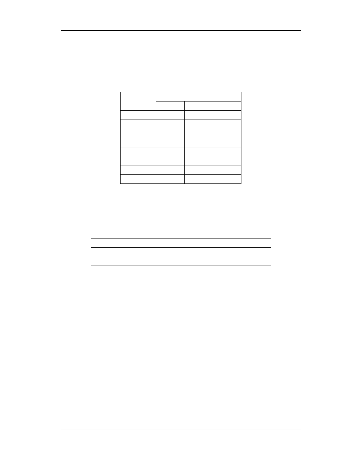
Below you will find our standard pin-out for DB25 audio contacts. This pin-out
is used for both Analog and digital audio routers. The same standard is used
by Tascam and Fostex.
DB25 Pin #
Channel #
Hot (+) Cold (-) GND
1 24 12 25
2 10 23 11
3 21 9 22
4 7 20 8
5 18 6 19
6 4 17 5
7 15 3 16
8 1 14 2
All audio contacts used on the routers are female type.
5.1 Unbalanced signals on the Modular Analog Audio Router
If you want to use the Modular Analog Audio Router with unbalanced audio
signals you connect these signals according to the following table:
VikinX device Unbalanced signal connection
‘+’ Audio
‘-’ Shield
‘GND’ Shield
28
Page 29
Modular Analog Audio Router Rev. 8
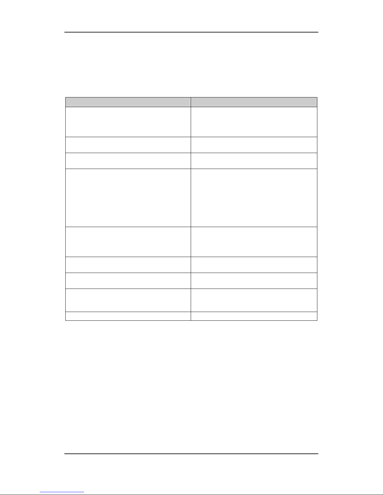
6 Before calling Network Support
The following table shows possible symptoms, and what to do in order to
correct possible error sources. Every user should read this before calling
Network Technical Support.
Symptom What to do…
The lower, GREEN LED on the Power Supply is
OFF.
No mains or battery power supplying the
frame. Check that the power supply is
connected properly. This includes check of all
connected power cords, etc.
The upper, RED LED on the Power Supply is
ON.
There is a power supply failure, indicating that
the power supply module must be replaced.
The Status LED on the Syscon card is RED. There is a card error, indicating that the Syscon
card must be replaced.
The Warn LED on the Syscon card is RED. An abnormal situation has occurred. See
Chapter 2.
If the router has redundant PSU modules, check
that both modules are properly installed, and
are working.
If the router has redundant Syscon cards, check
that both cards are properly inserted, and are
working.
The SYST.ERR. LED on one of the X-point cards
is RED.
A fault is detected on the X-point card. Check
that it is properly connected. If it is properly
connected, the X-point card needs
replacement.
A FAN LED on one of the X-point cards is RED. The fan speed is outside its legal range,
indicating that service is necessary.
The PWR. LED on one of the X-point cards is
RED.
Any of the voltages on the card is outside its
legal range, indicating that service in necessary.
The TEMP. LED on one of the X-point cards is
RED.
Any of the temperatures on the card is outside
its legal range, indicating that service is
necessary.
29
Page 30
Modular Analog Audio Router Rev. 8
7 Serial number overview
The following table shows the serial numbers of all parts of your Modular
Analog Audio Router. Please refer to these numbers when contacting Network
Electronics AS for product support.
Device / Part Part / Serial number
Frame, including all static cards
Power Supply Module #1
Power Supply Module #2, if included
X-point Card #1
X-point Card #2, if included
X-point Card #3, if included
X-point Card #4, if included
Syscon Card #1
Syscon Card #2, if included
GYDA-VX Card #1, if included
GYDA-VX Card #2, if included
30
Page 31

Modular Analog Audio Router Rev. 8
Notes
31
Page 32
Modular Analog Audio Router Rev. 8
Materials Declaration and EFUP
Materials declaration
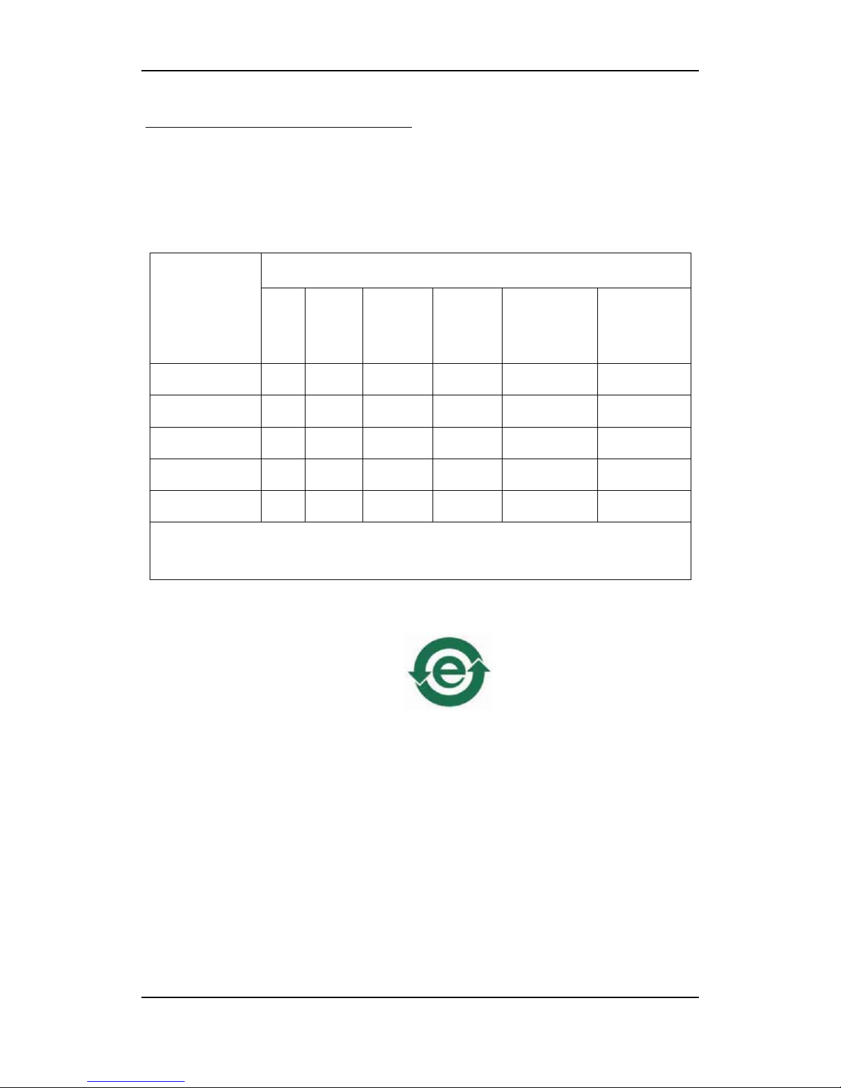
For product sold into China after 1st March 2007, we comply with the
“Administrative Measure on the Control of Pollution by Electronic Information
Products”. In the first stage of this legislation, content of six hazardous
materials has to be declared. The table below shows the required
information.
Toxic or hazardous substances and elements
組成名稱
Part Name
鉛
Lead
(Pb)
汞
Mercury
(Hg)
镉
Cadmium
(Cd)
六价铬
Hexavalent
Chromium
(Cr(VI))
多溴联苯
Polybrominated
biphenyls
(PBB)
多溴二苯醚
Polybrominated
diphenyl ethers
(PBDE)
FR-128128-A /
FR-6464-A
X O O O O O
XC-A-M3232 O O O O O O
SYSCON-128 X O O O O O
GYDA-VX (option) X O O O O O
POWER-SM O O O O O O
O: Indicates that this toxic or hazardous substance contained in all of the homogeneous materials for this
part is below the limit requirement in SJ/T11363-2006.
X: Indicates that this toxic or hazardous substance contained in at least one of the homogeneous materials
used for this part is above the limit requirement in SJ/T11363-2006.
Parts without any of the above mentioned hazardous substances are indicated
by the product marking:
Environmentally Friendly Use Period (EFUP)
EFUP is the time the product can be used in normal service life without leaking
the hazardous materials. We expect the normal use environment to be in an
equipment room at controlled temperature range (0ºC - 40ºC) with moderate
humidity (<90%, non-condensing) and clean air, not subject to vibration or
shock.
Where a product contains potentially hazardous materials, this is indicated on
the product by the appropriate symbol containing the EFUP. The hazardous
material content is limited to lead (Pb) in some solders. This is extremely
stable in normal use and the EFUP is taken as 50 years, by comparison with
the EFUP given for Digital Exchange/Switching Platform in equipment in
Appendix A of “General Rule of Environment-Friendly Use Period of Electronic
Information Products”. This is indicated by the product marking:
32
Page 33

Modular Analog Audio Router Rev. 8
50
It is assumed that while the product is in normal use, any batteries associated
with real-time clocks or battery-backed RAM will be replaced at the regular
intervals.
The EFUP relates only to the environmental impact of the product in normal
use, it does not imply that the product will continue to be supported for 50
years.
Recycling information
Network Electronics AS provides assistance to customers and recyclers through
our web site
http://www.network-electronics.com. Please contact Network
Electronics AS’s Customer Support for assistance with recycling if this site does
not show the information you require.
Where it is not possible to return the product to Network Electronics AS or its
agents for recycling, the following general information may be of assistance:
- Before attempting disassembly, ensure the product is completely
disconnected from power and signal connections.
- All major parts are marked or labeled to show their material content.
- Depending on the date of manufacture, this product may contain lead
in solder.
- Some circuit boards may contain battery-backed memory devices.
33
Page 34
EC Declaration of Conformity
Network Electronics AS
P.B. 1020, N-3204 SANDEFJORD, Norway
MANUFACTURER
AUTHORISED REPRESENTATIVE
(Established within the EEA)
Not applicable
A3232M / A6464M / A128128M
A3232S / A6464S
MODEL NUMBER(S)
Modular Analog Stereo Audio Router
DESCRIPTION
LVD 73/23/EEC
EMC 89/336/EEC
DIRECTIVES this equipment complies with
EN 55103-1:1996
EN 55103-2:1996
EN 60950-1:2006
HARMONISED STANDARDS applied in order to
verify compliance with Directive(s)
TEST REPORTS ISSUED BY Notified/Competent Body Report no:
Nemko 42192
Not applicable
TECHNICAL CONSTRUCTION FILE NO
2005
YEAR WHICH THE CE-MARK WAS AFFIXED
TEST AUTHORIZED SIGNATORY
MANUFACTURER AUTHORISED REPRESENTATIVE
(Established within EEA)
Date of Issue
2007-03-27
Place of Issue
Not applicable Sandefjord,
Norway
Nils B. Sannes
Name
Quality Manager
(authorized signature)
Position
 Loading...