

Page 1
PRE99-1424 DUAL ROUTER KIT INSTALL
INSTALLATION NOTES: READ ME FIRST!
Remove the Dual Fader panel completely from the console (the red Power and Signal cable is unplugged) prior to installing the
Dual Router Kit parts. A Dual Fader panel can be removed or installed while the console is powered and even on-air, however,
we recommend unassigning all buttons and turning off both channels prior to removing the panel. When the upgraded panel is
plugged back in, it assumes the panel button settings from the removed panel. Thus, if the channels were not turned off and
unassigned, unexpected audio could be sent to one or more buses when the new panel is plugged into a live console.
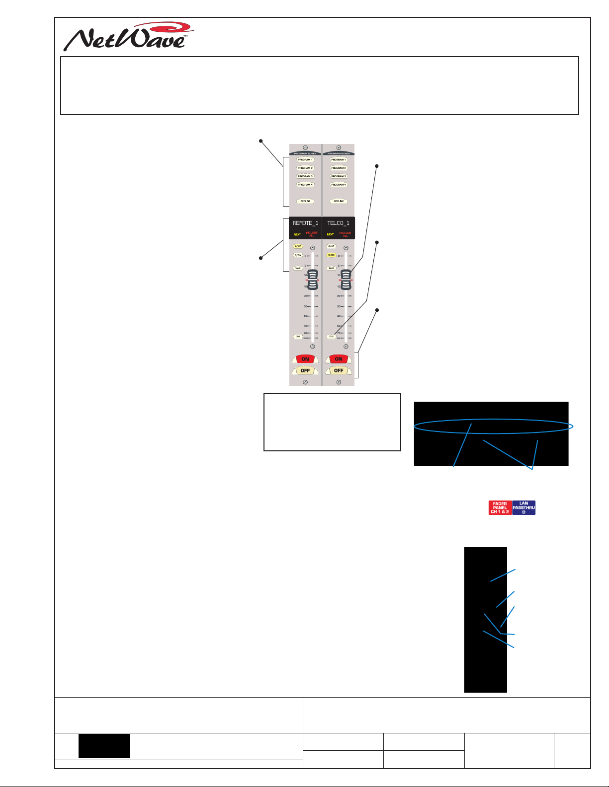
DUAL ROUTER PANEL CONTROL SUMMARY
The PROGRAM and OFFLINE buttons assign
BUS ASSIGNMENT BUTTONS
channels to one or more output buses. The
PGM bus signals are sent post-fader and
post on/off control. The OFFLINE bus is pre-
switch and typically set for pre-fader
operation when used with callers.
The panel’s Setup information can be displayed
by press/holding the left OFFLINE button. Use
the left UP/DN buttons to step thru the various
Setup displays. Releasing the OFFLINE button
returns the panel to normal display operation.
CHANNEL SOURCE SELECTION
The 10-character display normally shows the
active source, but when the UP or DN button
is pressed, to step through an alphanumeric
listing of the available sources on that channel,
the Next label lights to indicate the display
now shows a potential next source name.
Press/hold UP or DN to quickly scan through
the available sources. The Next label turns off
about three seconds after the last UP/DN
button press, or when a new source is taken.
To take the Next source, press TAKE while the
channel is off and Next is lit. If TAKE is pressed
when the channel is On, the buttons flash
three times indicating that Take is locked out.
Press/hold both UP and DN for three seconds to
light up INCLUDE ALL. This mode shows rarely
used source names. Press/hold UP and DN
again to exit the Include All mode.
A video on installing the
Dual Router upgrade kit
(dual_router_upgrade.wmv)
can be downloaded from any
GatesAir file download site.
These control functions are the same as on a
standard Dual Fader panel.
CHANNEL FADER
Controls the level of the channel source going to
the PGM buses. Typically, the Offline bus level is
not controlled by the fader (pre-fader), but the
console can be set up so the Offline bus is feed
post-fader. Note that the red line indicates the
unity gain position, which is where the fader
should normally be positioned.
CUE ON/OFF CONTROL
Press to light the Cue button which sends the
channel source, pre-fader and pre-on/off, to the
Cue speaker and to the operator headphones,
when AutoCue is lit. To turn cue off, press the lit
Cue button. Line sources will also automatically
turn cue off when the channel is turned on.
CHANNEL ON/OFF CONTROL
Press ON to assign the channel’s audio to the
selected buses. The button lights to indicate that
channel is on. Press OFF to remove the audio
from the selected buses. If the channel is set to
follow ready logic commands from a peripheral
device the Off button may not light or it may blink
to indicate an event has played on the peripheral.
10-Character Display Installation
UPGRADE KIT INSTALLATION PROCEDURE
1. Remove the four hex screws (2mm hex driver, PRE70-57) from the
Dual Fader panel. These screws are reused in step 9.
2. Lift the panel and unplug the red CAT5 cable (J5 on the Fader Panel).
3. Set the panel on the countertop. Pry up and remove the two display lenses.
They are reused in Step 6. Remove the two A/B labels (these may be held in place
by rubber cement) and the black foam on the IC sockets. These items can be discarded.
4. Insert the two 12-93 Displays into their sockets. Orient them so their mfg. label and
contact row is toward the rubber silos, as shown in the photo, upper right.
5. Set the two 80-2136 Next/Include All labels into the ledges on the rubber silos.
6. Snap the two display lenses back onto the panel. Verify the Next/Include All labels
remain seated in the rubber silos.
7. Turn the panel over (photo at right) and firmly seat the TINI processor board into its
socket, at about a 45° angle. Press the board back and down until the two latches snap
over the board, holding it in place.
8. Plug the blue cable (supplied) into jack J3. Hold the panel over the console slot and
plug the other end of the blue cable into the LAN Passthru jack (note that jack’s ID letter).
Plug the red cable back into jack J5. Fold and route the two cables so the panel can sit
evenly on the upper and lower chassis tabs without pinching either CAT5 cable.
9. Fasten the panel using the four screws removed in step 1 and continue to page 2.
TITLE
THIS DOCUMENT APPLIES TO
PRE99-1424
5300 Kings Island Drive • Mason, OH 45040 USA
513.459.3400 • fax: 513.459.5309 • www.gatesair.com
e-mail: tsupport@gatesair.com
DESIGNS BY PACIFIC RESEARCH & ENGINEERING
INSTALLATION AND USE GUIDE, DUAL ROUTER
UPGRADE KIT, FOR NETWAVE CONSOLES
DRAW N
SHEET
RM
1 OF 2
10-Character Display
DAT E
Nov 5, 2014
APVD.
contact row
Dual Router Upgrade Parts
Rubber silos for the
Next/Include All labels
Chassis RJ45 Label
Red cable
(from J5)
DWG. NO. R EV.
Blue cable
(from J3)
99-1810 TINI
Red CAT5 cable
J5
Blue CAT5 cable
J3
71-1424
D
Page 2
99-1424 DUAL ROUTER CONFIGURATION
DUAL ROUTER PANEL SETUP & CONFIGURATION
When the Dual Router panel is first powered up, the two 10-character displays will
show SOURCE***1* and SOURCE***2* for several seconds as the TINI processor
initializes. The Include All label red LEDs blink to indicate Setup Mode is active.
If either, or both, displays do not show SOURCE***1* and SOURCE***2*,
this indicates a display was either installed in reverse orientation or has a bent
pin. Power down the panel, remove the display lenses, and check how the displays
are installed into the two sockets.
The TINI processor initialization only takes a few seconds to complete, after which it
creates a broadcast message containing its MAC address (e.g., 00-60-35-ab-59-7f).
The left display shows various messages ( [FORMMSG], [MAKEMSG], etc.) during this
time. The TINI waits several seconds then re-sends the message. It will keep doing this
until it receives a response from its “parent device.” Needless to say, it won’t get a
response until the panel is connected to the VistaMax network and the VMCC app is
used to add the new dual router to a parent device, provision, and distribute updated
configuration files to the panel’s parent device.
Connect a straight-thru LAN cable from the VistaMax network switch to the rear panel
LAN pass-thru RJ45 jack for that dual router panel (it will have the same letter noted in
Step 8 in the installation procedure).
The Dual Router panel is now ready to be configured using two GatesAir apps: Community
Monitor and VistaMax Control Center (VMCC). Both of these must be running on the
VistaMax admin computer. It is assumed the admin computer, and the new Dual Router
TINI card, are now both connected to the VistaMax LAN switch.
1. On the VistaMax admin computer, Community Monitor, select View > Active BootP
Devices. This opens a window which lists any device currently sending out BootP
messages. The Dual Router TINI card should appear in this list as a VM-SS-D, 1/1 Dest
Source Selector. If so, the panel is properly connected to the VistaMax LAN.
If the TINI card does not appear in the Active BootP Devices window, verify your network cable is good and that it’s plugged
into the correct RJ45 jack on the NetWave. If it is, then you will have to verify the blue CAT5 cable is properly latched into the
Dual Fader jack J3 and into the Blue LAN Passthru RJ45 jack. Also note the letter (A, B, C, D) identifying that RJ45 jack. The
LAN cable must plug into the same lettered jack on the rear panel of the NetWave.
2. Once the TINI card is listed in the Active BootP Devices window, it can now be added to the VistaMax community using
VMCC. Select Community > File/Inspect Community. The new TINI card is listed with the name 00-60-35-XX-XX-XX. Uncheck
all of the other devices in the community, leaving only the TINI card checked. Click INSPECT, then click CONTINUE, then click
ACCEPT. The new Dual Router panel will appear at the bottom of the VMCC Community Explorer pane.
3. Click on the new panel’s name in the Explorer pane to show its settings in the edit pane. Its name will have a red flag (since
the MAC address has illegal characters), so its name must be changed to a unique name to both identify the NetWave console
and which two fader channels it controls. This name cannot have spaces, and is limited to ten characters), so use names like:
VT_FDR_78 (for Voice Tracking console, dual router in faders 7 & 8) or NW1_1112 (for NetWave 1, dual router in faders 11 & 12).
4. Assign the parent device. This is the VistaMax card frame that is Linked to the NetWave console.
5. Change its IP address. VMCC assigns a default IP address to the panel, but it should be changed to fall into line with the other
source selector panels. Typically, edge device IP addresses start at 192.168.100.201 and can go up to 192.168.100.254.
6. To this point, the system considers the new TINI card a Dual Source Selector. Right-click on the panel’s name in Community
Explorer and select “Convert to Dual Router” in the pop-up box. This action opens up a new edit pane so the NetWave console
(that the dual router is installed in) can be assigned by selecting the console from the drop down list.
7. Show the Dual Faders for that NetWave console (in the Community Explorer pane, click the + button next to the console’s
name). Click on the dual fader being upgraded (e.g., Fader 11 & 12). This opens up those faders in the edit pane. At the top of
the edit pane is a Bind to Router box. Click the drop down arrow and select the new Dual Router panel (e.g. NW1_1112).
8. Binding the Dual Router panel causes the Devices and Available Signals boxes to be populated. Select which sources and
macros should appear on each fader. Completely different signal sets can be set for each fader. Typically, limit the number of
sources to the most commonly used signals to make it easier for a board op to select a new source. If a source is not shown,
the board op can use the INCLUDE ALL function to show all sources included on the parent’s card frame.
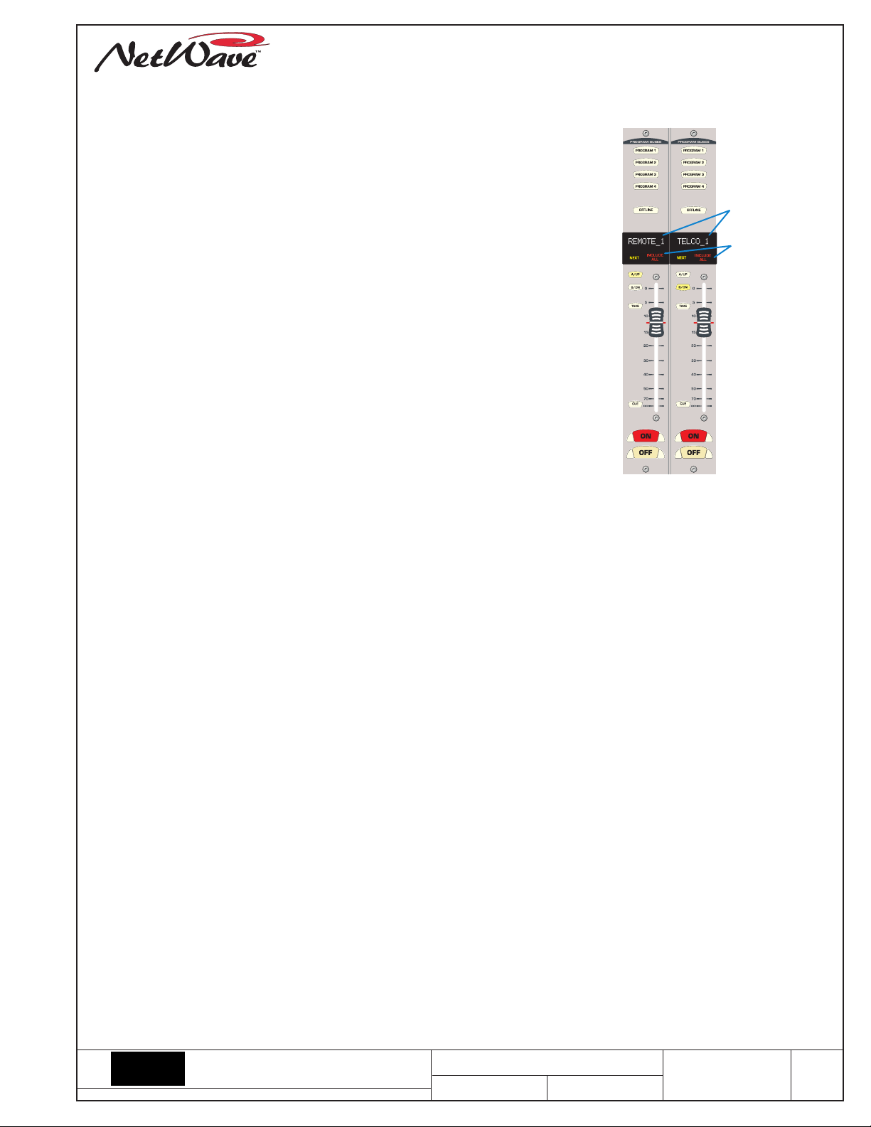
Dual Router Panel
10-character
Source Name
Displays
Include All labels
(blink when Setup
mode is active)
9. Once the sources are set, if there are no other changes required, switch VMCC to the Provisioning window. Click the Provision
button to update the configuration files. Click Distribute and use Normal Distribution to send updated configuration files to the
parent card frame.
10. It will take 30 - 60 seconds for the card frame to restart its edge device server and for the new Dual Router panel to display
[BOOTP OK], and a number of other messages, as it gathers its new configuration information. After another fifteen or so
seconds, you should see SILENCE listed on both faders. Press the UP or DOWN buttons to step through the source signals that
were included on each fader. Press TAKE to select a new source.
For technical support questions, contact GatesAir technical support by phone (217.222.8200) or e-mail (tsupport@gatesair.com).
5300 Kings Island Drive • Mason, OH 45040 USA
513.459.3400 • fax: 513.459.5309 • www.gatesair.com
e-mail: tsupport@gatesair.com
DESIGNS BY PACIFIC RESEARCH & ENGINEERING
TITLE
NetWave Dual Router Upgrade
SHEET DRAW N
2 OF 2
RM
DWG. NO. R EV.
71-1424
D
 Loading...