

Page 1

NWTAP-100 user guide
1
Netwave Proprietary and Confidential
NWTAP-100
Wireless Tap
User Guide
Preliminary Release 1.0, Issue 2
March 12, 2007
Netwave Co., Ltd.
Page 2

NWTAP-100 user guide
2
Netwave Proprietary and Confidential
Contents
1. Overview ...................................................................................................................3
1.1. Introduction........................................................................................................3
1.2. Product Description...........................................................................................4
2. Installation...............................................................................................................11
2.1. Unpacking and Content Checking...................................................................11
2.2. Remove Current Tap.......................................................................................12
2.3. Install the Wireless Tap...................................................................................12
2.4. Attach the Antenna..........................................................................................13
2.5. Insert the Power .............................................................................................. 14
2.6. Check for Proper Operation ............................................................................14
2.7. Performance Measurement.............................................................................16
3. WLAN Site Survey and Planning.............................................................................17
3.1. Location...........................................................................................................17
3.2. Radio Link Path...............................................................................................17
3.3. RF Channel Selection .....................................................................................18
3.4. Performance check .........................................................................................18
4. Configuration...........................................................................................................19
4.1. Webui based configuration..............................................................................19
4.2. WIRELESS......................................................................................................22
4.3. Wireless/Basic submenu.................................................................................23
4.4. Wireless/Security submenu.............................................................................23
4.5. Wireless/Access Control submenu..................................................................24
4.6. Wireless/Advanced submenu..........................................................................25
4.7. TOOLS ............................................................................................................ 26
4.8. Gateway .......................................................................................................... 27
4.9. Telnet based configuration..............................................................................28
4.10. SNMP based configuration..............................................................................31
4.11. Software upgrade............................................................................................31
5. Troubleshooting.......................................................................................................32
5.1. Troubleshooting for various symptoms............................................................32
5.2. Disassembling the wireless tap.......................................................................33
6. Appendix .................................................................................................................38
6.1. Ordering table..................................................................................................38
6.2. NWTAP-100 specifications..............................................................................38
6.3. FCC warning ...................................................................................................41
Page 3

NWTAP-100 user guide
3
Netwave Proprietary and Confidential
1. Overview
1.1. Introduction
This document describes the features of the wireless tap NWTAP-100 as well as how
it can be installed to provide the most effective service to end users.
The NWTAP-100 is an outdoor hardened wireless lan access point solution which
uses an internal cable modem as the backbone interface and AC line power from the
feeder cable for power. The wireless LAN tap-off is an all-in-one unit which consists
of a cable modem, WiFi access point, power supply unit, antenna and tap-off in an
outdoor-hardened housing.
It provides a low cost and easy to install WiFi access hotspot to homes and
businesses by simply removing the old tap and installing the wireless tap.
Standards based
The internal cable modem is DOCSIS 2.0 compliant based on the Broadcom
BCM3349. It is fully interoperable with all CMTS models available in the market
today.
The internal WiFi is based on the 802.11g standard which is backwards compatible
to the 802.11b. The wireless chipset is based on the Broadcom BCM4318.
Security
Security is of utmost importance in todays wireless networks which are exposed to
hackers and other mallicit users. The NWTAP-100 fully supports all the latest 802.11
security enhancements including WPA2.
Future proofed
The NWTAP-100 supports remote software upgrade via TFTP. The modem will
maintain the current version of software while downloading the new version in order
to provide crash proofing. Netwave will continue to include enhancements and
customizations to the existing software so that customers can continue to use the
wireless tap most effectively for many years.
Flexible service platform
The software running the wireless tap is a full featured gateway which can be used to
support commercial high speed access to homes and offices or provide public
hotspot service.
The flexible antenna mounts can be used to support a tap housing mounted antenna.
Since the antenna output is based on an SMA connector, various off-the-shelf
antennas may also be used.
The unit can be strand mounted or can be mounted at the side of buildings and
provides WiFi access as well as wired CATV signals.
Page 4
NWTAP-100 user guide
4
Netwave Proprietary and Confidential
1.2. Product Description
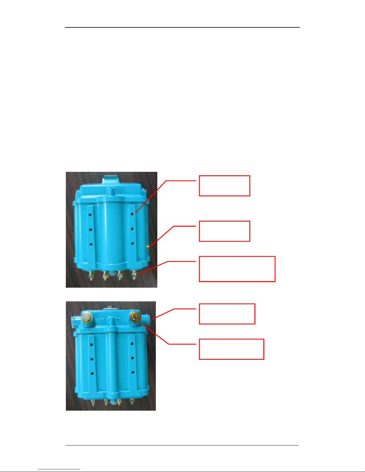
1.2.1. NWTAP-100
The following is a list of NWTAP-100’s main features.
Includes an internal DOCSIS 2.0 cable modem
Trunk AC power can be used to power the wireless tap
Trunk input and output as well as subscriber output ports are in the same
configuration as a conventional tap-off
Conventional tap-off can be removed and replaced with the wireless tap
without impacting the electrical characteristics of the CATV signal
coming off of the 5C connectors
802.11b/g compliant wireless lan service is provided
Antenna connection is made via an SMA female connector located at the
side of the wireless tap
8-tap front
8-tap back
Antenna fixing
screw holes
Antenna SMA
connector
Subscriber F-connector
with terminating load
5/8” input/output
connector
Center pin seizing
screw cover
Page 5
NWTAP-100 user guide
5
Netwave Proprietary and Confidential
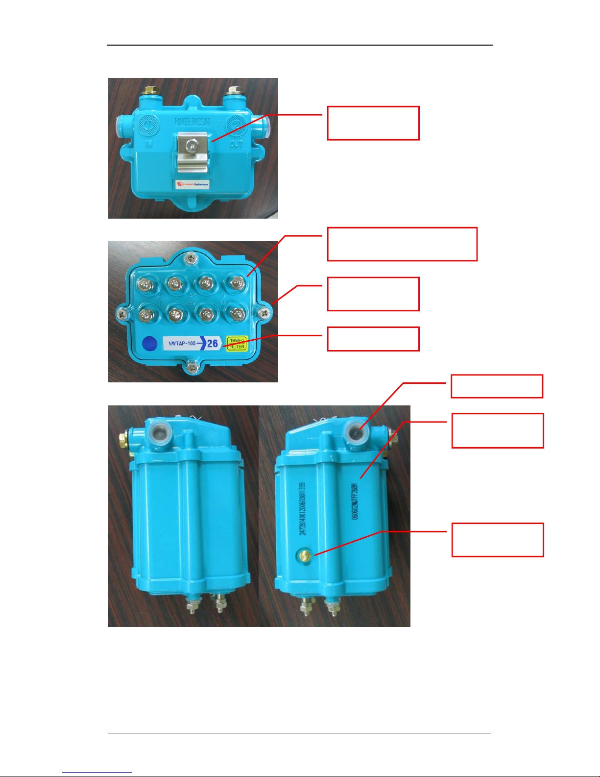
8-tap top
8-tap bottom
8-tap sides
Strand mounting
fixture
Subscriber F-connector with
terminating load
Faceplate
screws
Product serial
marking.
Antenna SMA
connector
Tap dB value
Plastic cap
060602 : production year+month+date
NWT : product name
FF26BA : MAC address which follows
the OUI “000200”
Page 6
NWTAP-100 user guide
6
Netwave Proprietary and Confidential
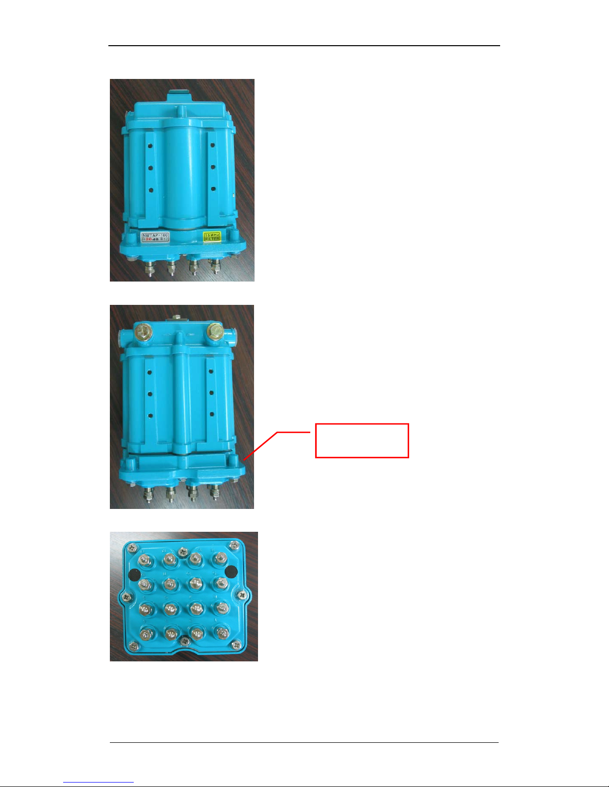
16-tap front
16-tap back
16-tap bottom
16-port faceplate
adaptor
Page 7
NWTAP-100 user guide
7
Netwave Proprietary and Confidential
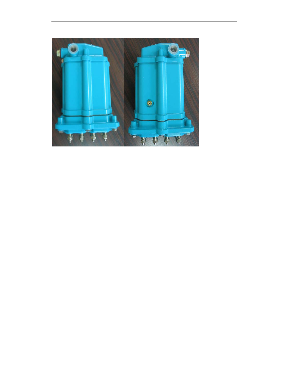
16-tap sides
Fig. 1 NWTAP-100 external features
Page 8
NWTAP-100 user guide
8
Netwave Proprietary and Confidential
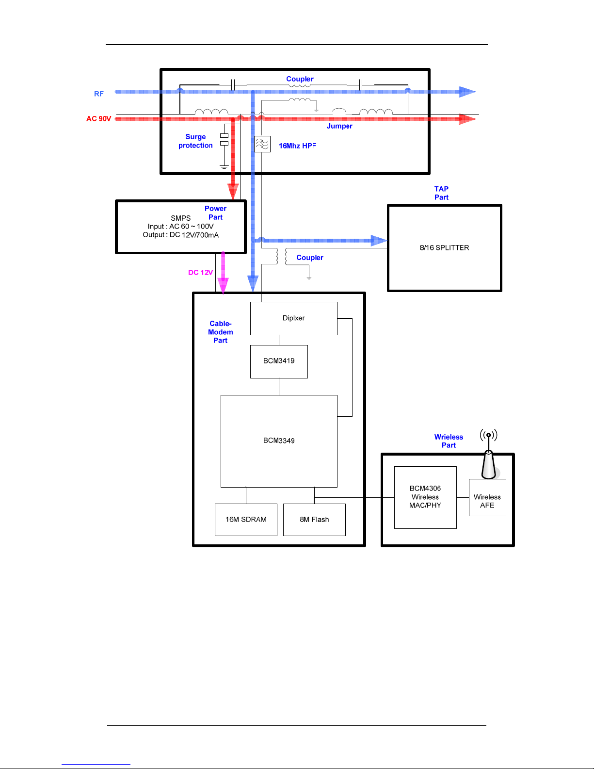
Fig. 2 NWTAP-100 block diagram
As shown in fig. 2, the trunk line RF is sampled to the tap-off splitter circuit as in a
conventional tap-off but part of this signal is also coupled to an internal cable modem.
The cable modem then transfers the Ethernet packets to the wireless part for
communication via 802.11b/g radio.
The AC power existing in the trunk network is also sampled by the power part so that
the DC powering for the cable modem and the wireless lan can be provided.
Page 9
NWTAP-100 user guide
9
Netwave Proprietary and Confidential
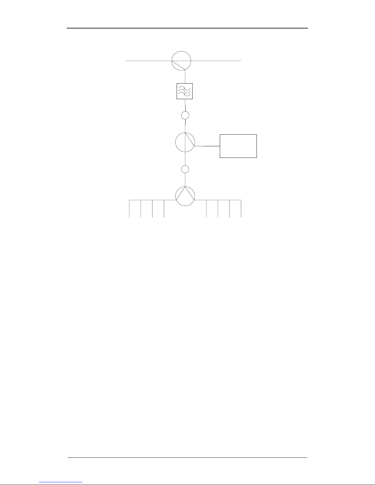
cable
modem
-Y dB
-0.5dB
(connector)
-0.5dB
(connector)
-17dB
-12dB
Main spliiter
-1dB
trunk IN trunk OUT
subscriber OUT
-1dB
(16Mhz HPF)
Fig. 3 RF signal level within the wireless tap
The above figure shows the RF signal level attenuation as they pass through the
wireless tap with 8 subscriber ports.
The RF signal level output at the subscriber ports are attenuated by approximately,
-Y-1-0.5-1-0.5-12 dB
The actual tap value in dB displayed at the bottom of the tap excludes the 1dB
attenuation for the 16Mhz HPF and -1dB attenuation for the cable modem.
-Y-0.5-0.5-12 dB
The RF signal level output at the cable modem is attenuated by approximately,
-Y-1-0.5-17 dB
This level should be considered so that the appropriate RF level is input into the
cable modem. The cable modem input level should be within the range 15~+15dBmV.
The main splitter is implemented in the form of a plug-in type coupler which allows
this value to be easily changed in the field as shown in section 5.2.2.
Page 10

NWTAP-100 user guide
10
Netwave Proprietary and Confidential
1.2.2. Antenna
The antenna connection via a standard SMA connector and a flexible antenna
attaching structure on the housing consisting of 12 screw positions allow a wide
range of antennas to be supported. If the antenna size is too big for direct attachment
to the housing, it maybe attached to a separate stable structure and connected via
RF cable from the SMA connector.
“This device uses an SMA type connector only”
RF exposure compliance information.
“The antenna used for this transmitter must be installed to provide a separation
distance of at least 20cm from all persons and must not be co-located or operating in
conjunction with any other antenna or transmitter.”
Page 11
NWTAP-100 user guide
11
Netwave Proprietary and Confidential
2. Installation
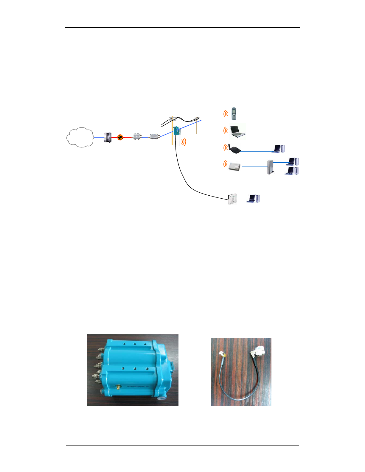
As shown below in the system configuration diagram, the wireless tap is by default a
replacement for the conventional tap which is strand mounted. The strand mounting
allows the wireless tap to have a wide open coverage which is beneficial towards
improving signal reception on the client side.
Fig. 4 System configuration
2.1. Unpacking and Content Checking
The box should be unpacked to reveal the following components.
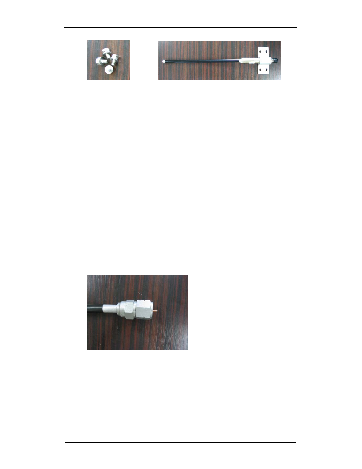
NWTAP-100 main body
Antenna cable (SMA male-N male)
Four screws for antenna holder fixture
Antenna option A (omni directional), or
Antenna option B (directional patch)
Please note that other antenna options apart from A and B are also be available.
Please refer to a separate manual in this case.
NWTAP-100 Antenna cable
2.4Ghz
ONU
TBA
CMTS
Internet
cable modem
Wireless tap
Page 12
NWTAP-100 user guide
12
Netwave Proprietary and Confidential
Antenna fixture screws Omni directional antenna
Fig. 5 Contents
2.2. Remove Current Tap
The wireless tap will replace the conventional tap. The conventional tap to be
replaced shall be selected based on the site survey and planning result..
Identify and record the dB value of the tap
If the tap is currently passing AC power, block the AC power by turning
off the UPS or removing the fuse from the power passing amplifier
Remove the subscriber cables connected to the tap
Remove the shrink tubing around the trunk connector
Separate the strand from the top of the tap
Unscrew the seizing screw and remove the trunk connector from the tap
and remove the tap
Remove the trunk connector from the trunk cable
Note : the wireless tap may also be installed anywhere on the strand or at
the side of buildings as long as an input coaxial cable provides the
DOCSIS signal and AC powering
2.3. Install the Wireless Tap
Connect the trunk connector(main nut and back nut) to the trunk cable
Mount the wireless tap on the strand using the strand mounting fixture
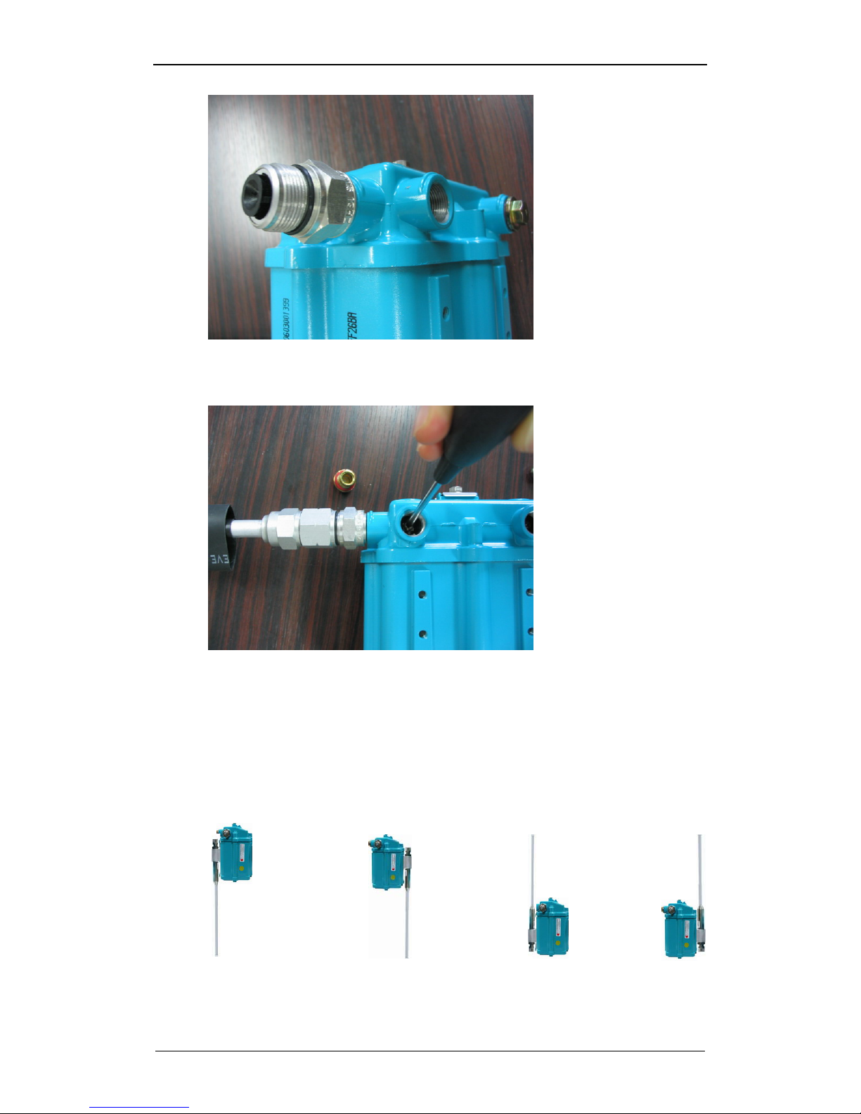
Install the body connectors to the wireless tap housing after removing
the plastic cover from the input/output ports and unscrewing the seizing
screw
Page 13
NWTAP-100 user guide
13
Netwave Proprietary and Confidential
Insert shrink tubing into the trunk cable on the input and output ports
Mate the main nut and trunk cable to the body connector and tighten
Secure the center conductor into the tap housing using the seizing screw
Shrink the tubing with a propane torch
2.4. Attach the Antenna
Select the Antenna type based on the site survey and planning result
Select the Antenna position based on the site survey and planning result.
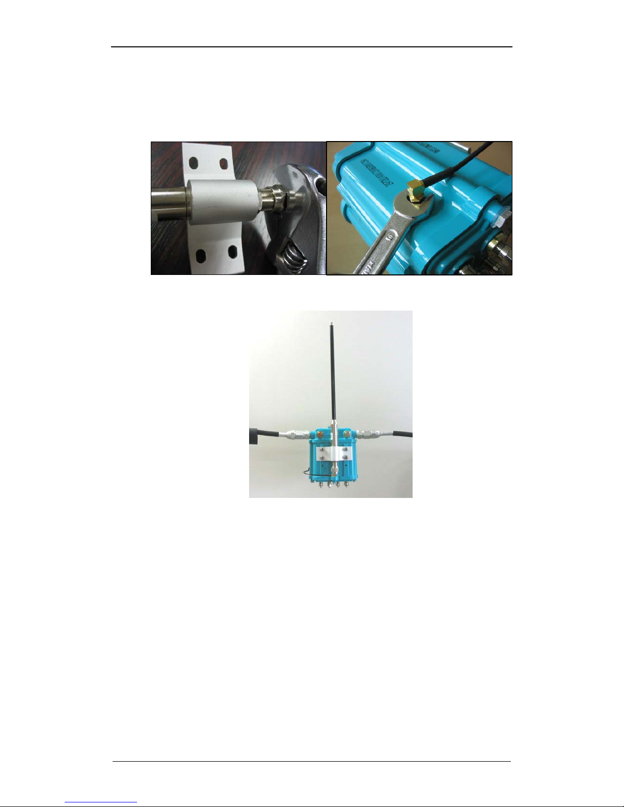
Typically the four options shown below are available
Fig. 6 Antenna position options
Type 1 Type 2 Type 3 Type
Page 14
NWTAP-100 user guide
14
Netwave Proprietary and Confidential
Attach the antenna to the housing using the four screws
Use the antenna cable to connect the N-type connector on the antenna
to the SMA type connector on the housing, In order to ensure the best
wireless signal level, the connectors should be tightened well
Fig. 7 Antenna connector tightening
Fig. 8 Assembled wireless tap without the shrink tube and strand mounting
In case of the patch antenna, the antenna direction should be adjusted to
focus the signal towards the client
2.5. Insert the Power
Insert power into the wireless tap by turning ON the UPS or inserting the
fuse into the power passing amplifier
2.6. Check for Proper Operation
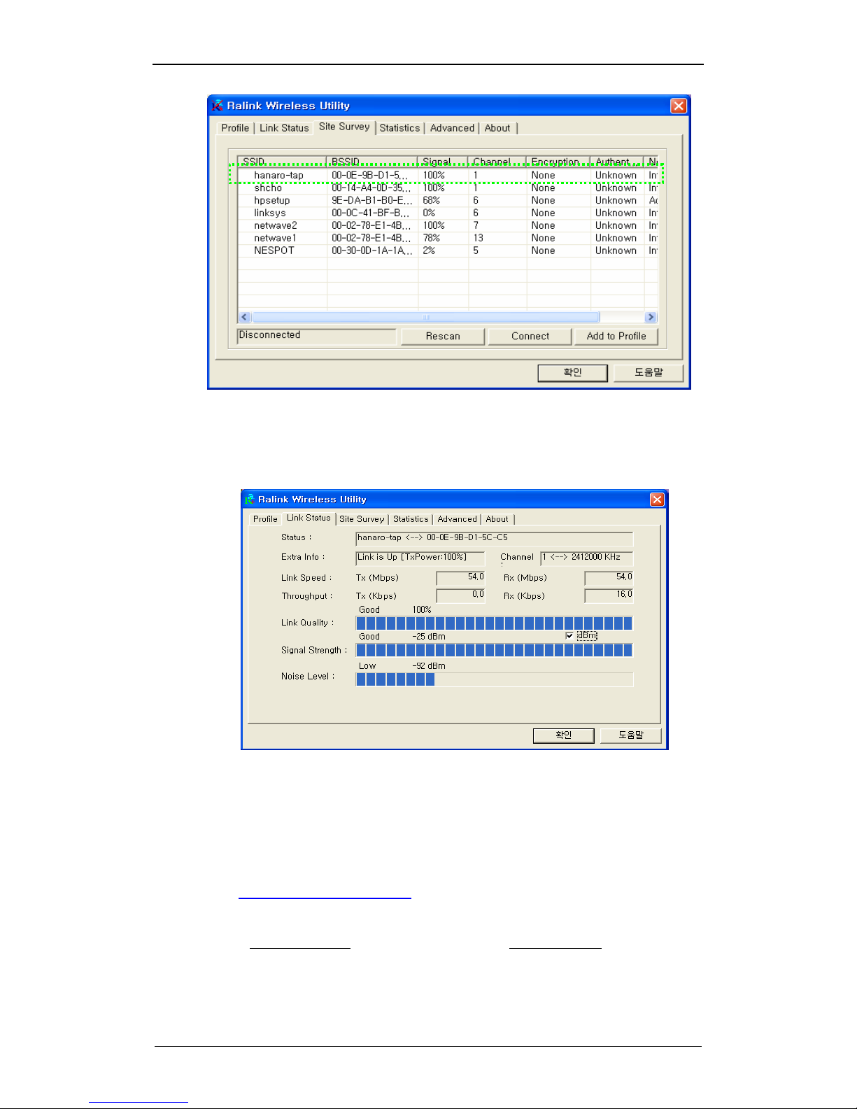
Using the notebook with wireless LAN and a client utility, the wireless
channels are scanned for SSID
If the SSID used by the wireless tap is found(e.g. “hanaro-tap”), the
wireless connection should be made to this SSID. The default channel is
1
Page 15
NWTAP-100 user guide
15
Netwave Proprietary and Confidential
Verify that the wireless signal strength(the received power level) shown
by the client utility when the client is below or close to the wireless tap is
>-55dBm
Check the notebook IP using the “ipconfig” command in the command
prompt and verify that it has acquired the correct IP from the CMTS
DHCP server or has acquired the IP 192.168.x.x from the DHCP server
in the wireless tap. The wireless tap has an internal DHCP server which
takes over when an external DHCP server is not available.
Access the web management page of the wireless tap via the address
“http://192.168.100.1:64680
”. The special port number 64680 is used in
order to secure the web access as much as possible.
If web access is still not possible, please set the static IP of the notebook
to 192.168.100.10
and the subnet mask to 255.255.255.0
Login using the id/password = admin/cableroot
As described in section “4.1 Webui Based Configuration”, the proper
operation of the cable modem is verified
Page 16

NWTAP-100 user guide
16
Netwave Proprietary and Confidential
2.7. Performance Measurement
At the client location, the signal strength shown by the client utility should
typically be >-75dBm. At such a power level, wireless tap can produce
the maximum throughput which would be a limitation of the cable
modem.
Once the client has established RF link to the wireless tap and has
acquired the proper IP address to be able to access the Internet, the
performance test for actual TCP data throughput can be performed
The throughput can be checked by using any of the three following
methods. In order to make the throughput shown as reliable as possible,
the server accessed should preferably belong to the MSO or ISP that
has the wireless tap connected to it’s CMTS.
1) A speed checking web site can be used to check the throughput
2) FTP can be performed
3) Web download can be performed
Any of the three methods will show the TCP data throughput which
should will be limited mostly by the throughput of the cable modem. Even
the raw data throughput of the 802.11g wireless is 54Mbps, the actual
TCP throughput can reach roughly half this rate. However, the cable
modem throughput is mostly limited by the MSO to be less than 15Mbps.
Page 17

NWTAP-100 user guide
17
Netwave Proprietary and Confidential
3. WLAN Site Survey and Planning
The 802.11b/g standard uses the 2.4Ghz frequency. This high frequency radio
travels in a straight forward line and a clear LOS(Line Of Sight) path between the
wireless tap antenna and the subscriber antenna is the ideal situation.
However in the real world situation, the 2.4Ghz frequency used by the wireless lan
belongs to the ISM/UNII band which is shared with various other applications
including the digital cordless phone. Also, current and future obstructions need to be
considered. Therefore, a strong RF signal is a must.
The most basic steps for the installation include.
1. Identify the target subscriber location
2. Determine the location of the tap to be replaced or location where the
wireless tap will be installed
3. Choose and install the antenna for the best radio link
4. Perform a RF scan around the wireless tap and choose the optimal RF
channel
5. Perform a throughput check so that greater than 10Mbps throughput
performance for TCP or UDP data can be achieved
3.1. Location
Select the location which provides the closest distance and minimal
obstruction to the current or potential future client location. The ideal
case would be LOS.
Since the wireless tap is most easy to install if the legacy outdoor strand
mounted tap is replaced, a legacy tap location with good reach of client
location should be taken as first priority.
If such a tap is not available, a separate strand mounting or mounting at
the side wall of a building or similar tall structure should be considered.
In such a case, the availability of CATV coaxial cable with AC power and
DOCSIS signal should be considered.
3.2. Radio Link Path
After the location is selected and wireless tap installed, the radio link
path should be measured and determined if adequate signal level can be
received at both ends.
Perform a site survey by measuring the radio signal strength at various
locations around the wireless tap where current or future clients maybe
located.
Radio signal level detection procedures are described in more detail in
the “Installation” chapter.
If the radio signal level is determined to be below the required level, the
antenna position and/or direction should be adjusted first. If this is also
not adequate, the antenna type maybe changed to a type with more
directivity. However a more directive antenna implies that the radio
signal tapering outside of the target area needs to be considered for
future clients.
Also, the client side AT(Access Terminal) device can be changed to one
with higher antenna gain for better radio detection.
Page 18
NWTAP-100 user guide
18
Netwave Proprietary and Confidential
3.3. RF Channel Selection
As described in the “Installation” chapter, the frequency band occupied
by the wireless LAN can be scanned using a client utility or it can be
scanned using measurement equipment such as spectrum analyzer.
The client utility can detect the presence and signal strength of all
wireless LAN channels that can be detected while a measurement
equipment can also detect the presence of all other signals that share
the ISM/UNII band.
After the RF scanning is completed, the operating channel can be
selected based on the results.
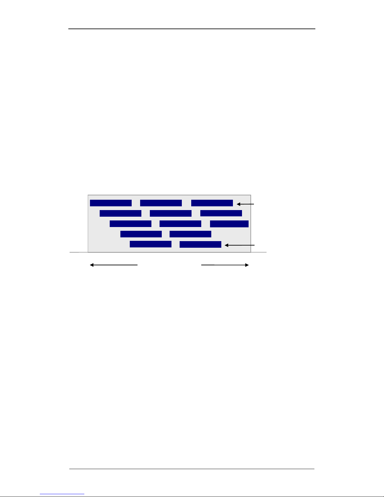
As shown below, if any other wireless LAN channel can be detected, the
selected channel should be spaced at least 4 channels apart to minimize
signal overlap. If this is not possible, the selected channel should be
spaced as far away from other wireless channels as possible. At the
same time, it should be free of RF signals from other equipment that
share the ISM/UNII frequency.
If a particular channel has a signal strength of <-90dBm, this channel can
be considered unoccupied during the channel planning.
Fig. 9 Channels and frequency coverage
3.4. Performance check
The throughput performance can be checked as described in section
“2.7 Performance Measurement”
ISM Band
Channel bandwidth
- 802.11b : 22㎒
- 802.11
g
: 20㎒
2400 MHz
2484 MHz
Channel number
Page 19
NWTAP-100 user guide
19
Netwave Proprietary and Confidential
4. Configuration
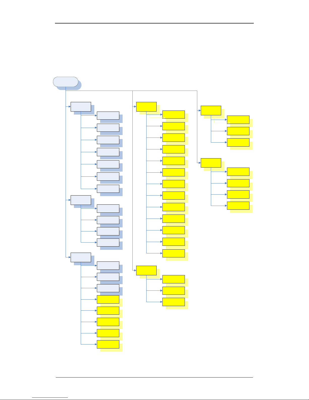
4.1. Webui based configuration
4.1.1. Web menu structure
Modem
Login
Wireless
Tools
Information
Status
Downstream
Upstrream
Upstrream
burst
Operation
configuration
Event log
Basic
Security
Access control
Advanced
Password
Factory default
Operation mode
UI
authentication
Port
configuration
Client list
Trace route
Ping
Gateway
Information
Setup
DHCP
Static Lease
Time
Options
MAC filtering
IP filtering
Port filtering
Forwarding
Port triggering
Pass through
DMZ host
RIP
RIP setup
Routing setup
Static routing
Parental
Control
User setup
Basic
Tod filter
Event Log
Firewall
Content filter
Event log
Remote log
Blue : Menu available in always available
Yellow : Menu available if NAT is selected from the “operation mode” menu
Page 20
NWTAP-100 user guide
20
Netwave Proprietary and Confidential
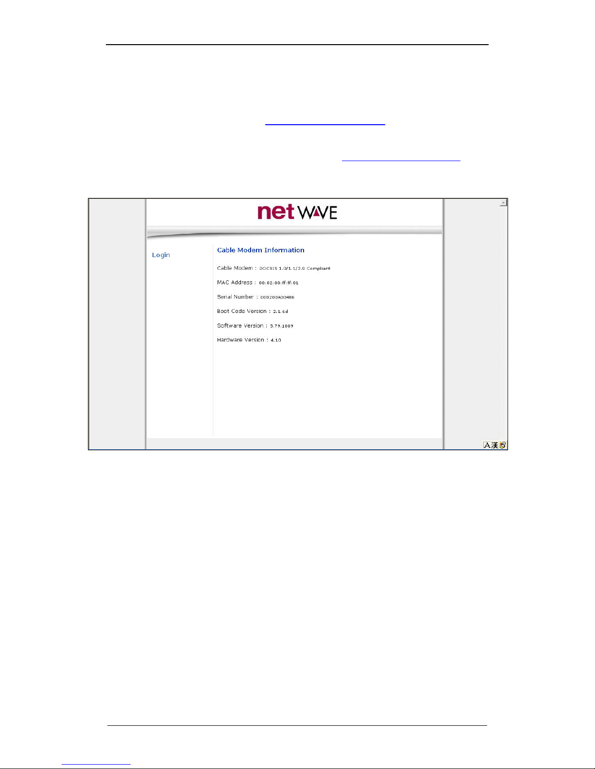
4.1.2. Login method
After establishing wireless link to the wireless tap web page maybe
accessed locally using http://192.168.100.1:64680
. This IP address can
be accessed if the PC’ s IP address is set to 192.168.100.x or the PC
has acquired IP via a DHCP Server.
Remote web access is possible through http://cm ip address:64680.
When “ Login” menu is selected, ID/Password is requested.
ID/Password = admin/cableroot
Page 21
NWTAP-100 user guide
21
Netwave Proprietary and Confidential
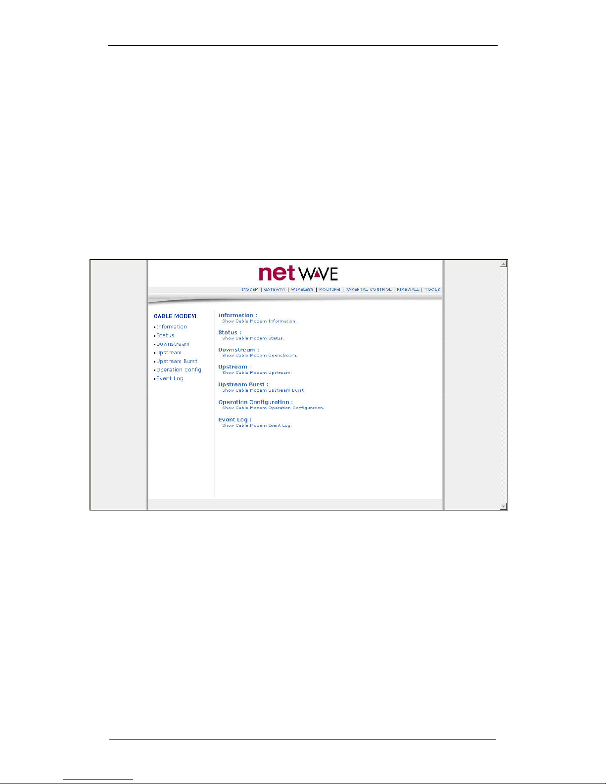
4.1.3. MODEM
This page shows the relevant pages related to management of the cable
modem internal to the wireless tap.
Information : shows the cable modem mac address or it’ s software and
hardware version.
Status : shows the current status of the cable modem.
Downstream : shows whether the cable modem is locked to the
downstream signal.
Upstream : shows whether the cable modem is locked to the upstream
signal.
Upstream Burst : shows the upstream burst signal information.
Operation Config : shows the config file information for the modem.
Event log : shows the event log of the modem.
Page 22
NWTAP-100 user guide
22
Netwave Proprietary and Confidential
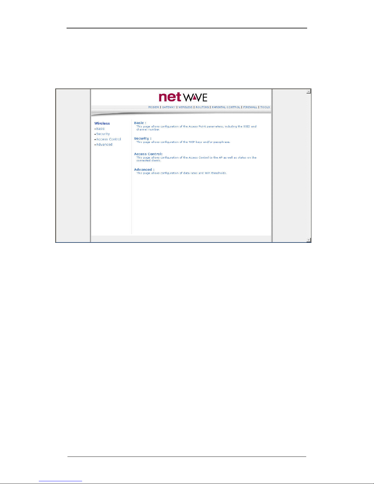
4.2. WIRELESS
This menu is displayed when the “ WIRELESS” menu is selected on
the top right corner.
Four submenus show the wireless LAN related information.
Page 23
NWTAP-100 user guide
23
Netwave Proprietary and Confidential
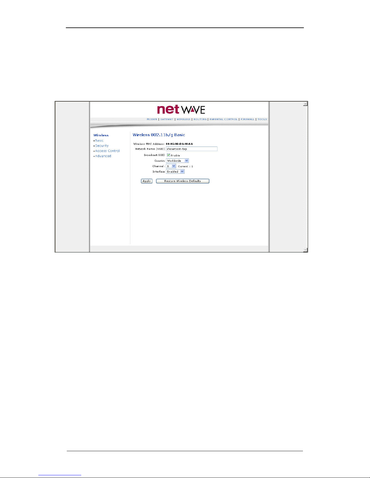
4.3. Wireless/Basic submenu
Network Name (SSID) : the default SSID is “hanaro-tap”
Broadcast SSID : SSID maybe broadcast or hidden (default : enable)
Channel : used to set the WLAN channel (default : 1)
Interface : disable or enable WLAN (default : enable)
4.4. Wireless/Security submenu
is used to set security parameters related to the radius server.
Page 24
NWTAP-100 user guide
24
Netwave Proprietary and Confidential
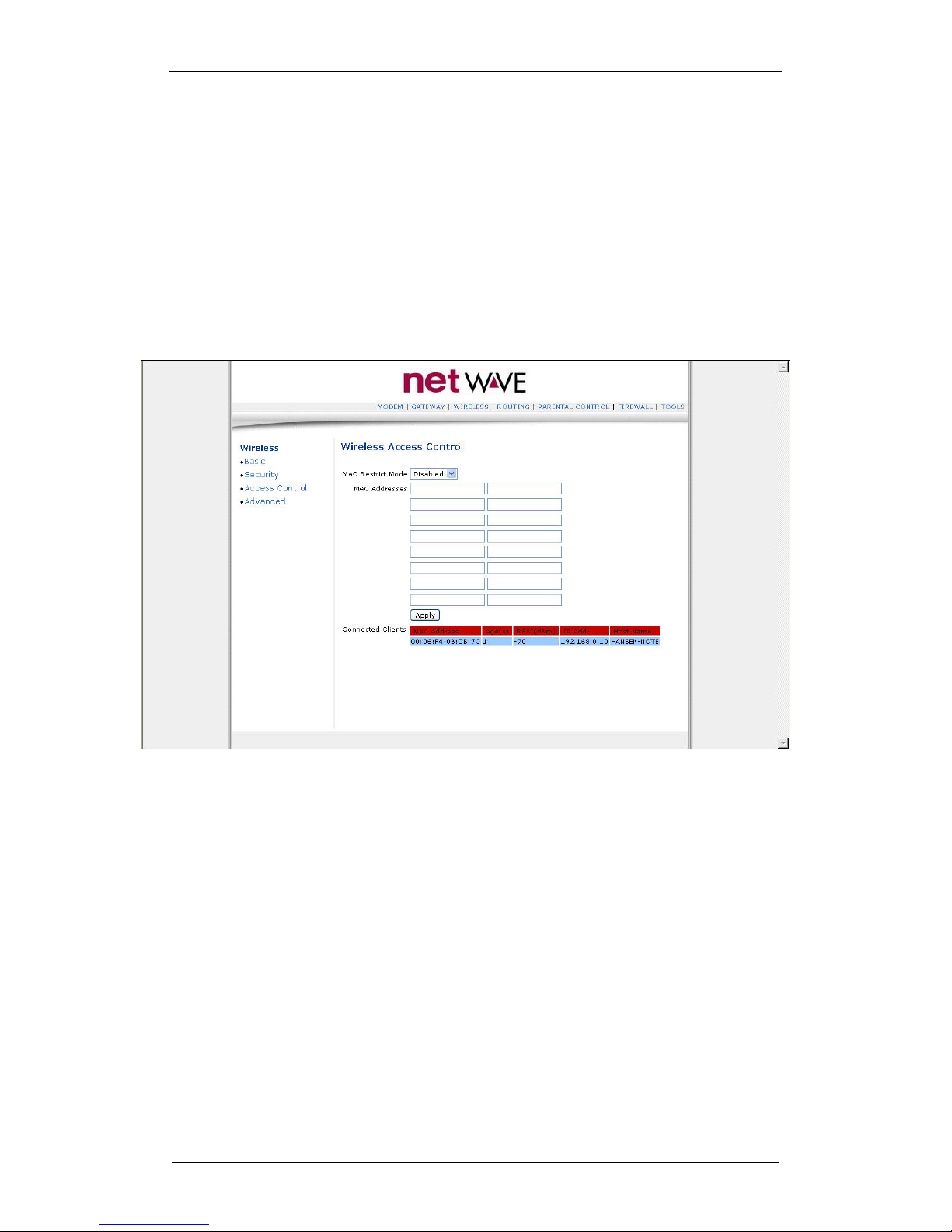
4.5. Wireless/Access Control submenu
MAC Restrict Mode : the following rules will be applied to the mac
addresses listed in the “ MAC Addresses” field (in the format
00:02:00:5b:63:01)
– Disabled : not used(default)
– Allow : only listed MAC Addresses may establish link via
WLAN
– Deny : is the opposite of allow and only listed MAC Addresses
will be denied link via WLAN
– Connected Clients : shows the clients currently connected via
WLAN
Page 25
NWTAP-100 user guide
25
Netwave Proprietary and Confidential
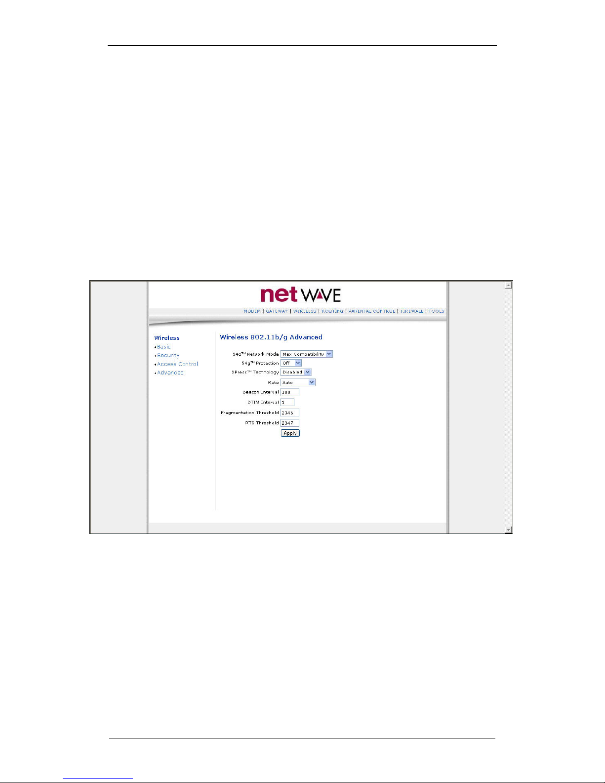
4.6. Wireless/Advanced submenu
54g™ Network Mode : WLAN operation mode is selected.
– 11b Only : only 11b link is supported
– 54g Only : supports only 54g™(Broadcom) and 11g link
– Max Compatibility : provides maximum compatibility by
supporting all 54g™, 11b & 11g clients
– Max Performance : supports only 54g™ and provides the
highest throughput
54g™ Protection : In Auto mode the AP will use RTS/CTS protection to
improve 802.11g performance in mixed 802.11g + 802.11b networks.
Turn protection Off to maximize 802.11g throughput under most
conditions.
Rate : Forces the transmission rate for the AP to a particular speed. Auto
will provide the best performance in nearly all situations. (default : auto)
Page 26
NWTAP-100 user guide
26
Netwave Proprietary and Confidential
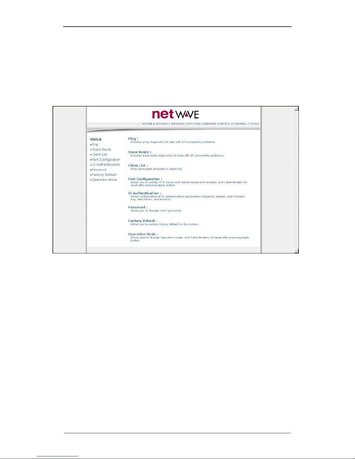
4.7. TOOLS
This menu is displayed when the “ TOOLS” menu is selected on the
top right corner.
– Password : web access ID and password maybe used.
– Factory Default : reset to factory default.
– Operation Mode : select between bridge and NAT mode for
wireless LAN operation.
Page 27
NWTAP-100 user guide
27
Netwave Proprietary and Confidential
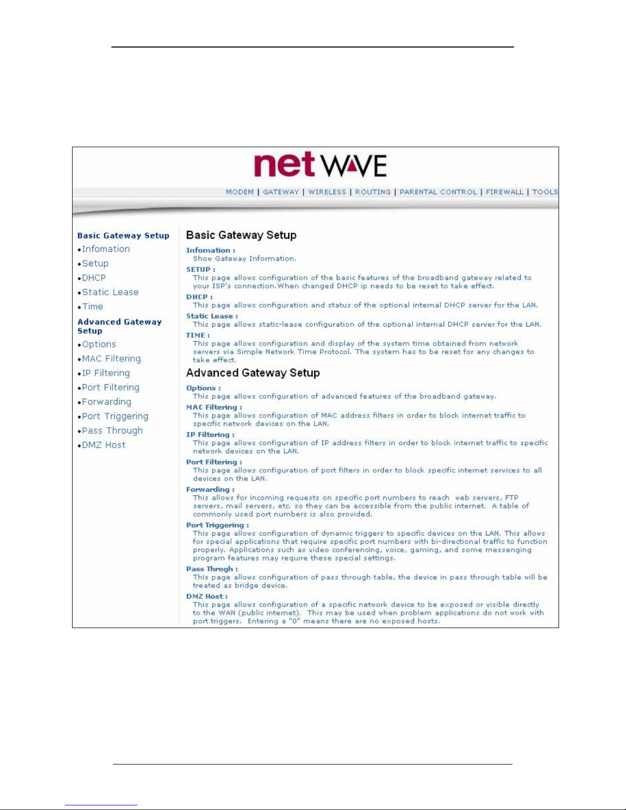
4.8. Gateway
Contains all the settings related to the gateway features.
This menu is enabled only when NAT is enabled via the “operations
mode” menu.
The functions below are intuitive from the explanations on the web page.
Page 28
NWTAP-100 user guide
28
Netwave Proprietary and Confidential
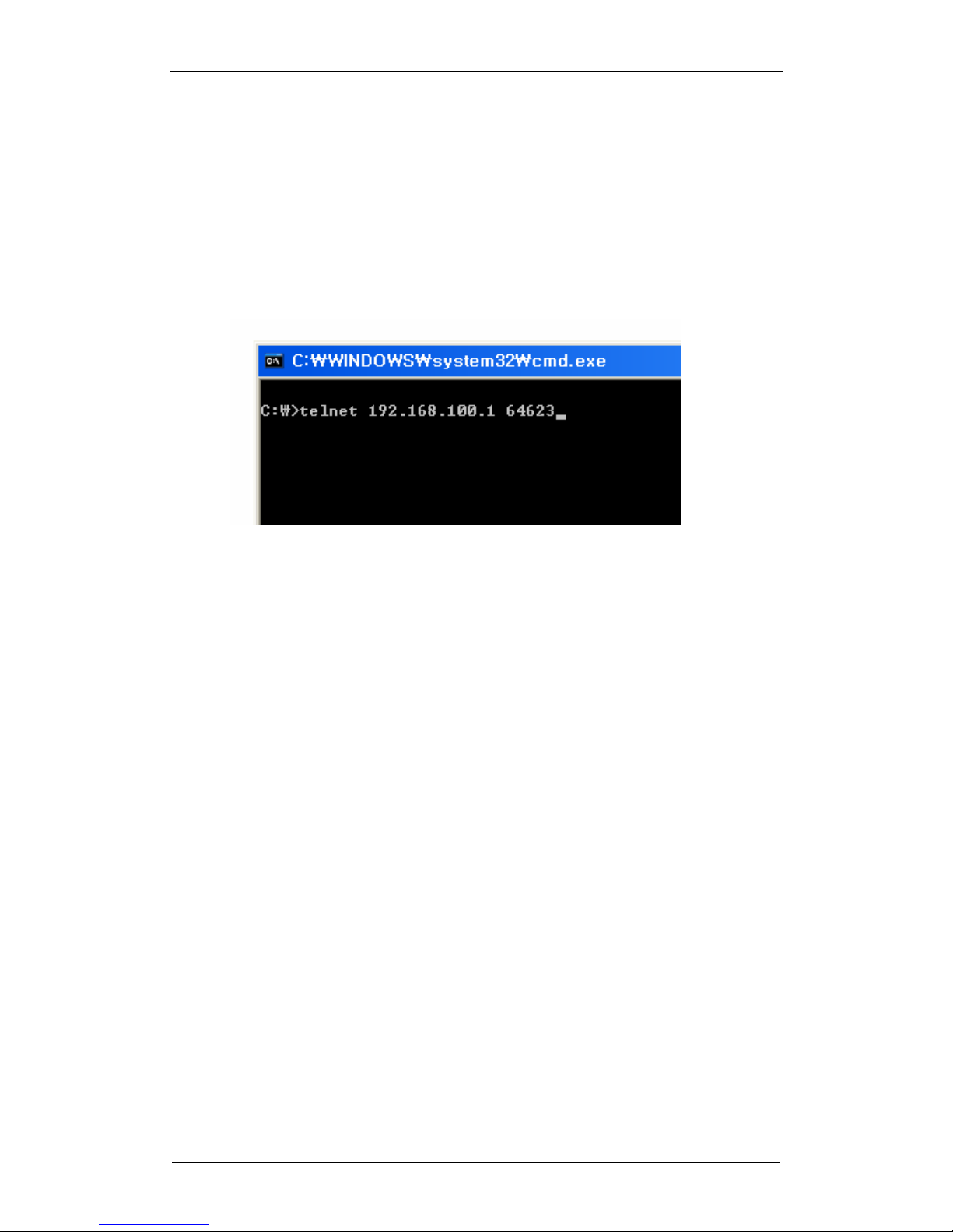
4.9. Telnet based configuration
4.9.1. Telnet access
Similar to the webui, Telnet access can be made locally through the
wireless link
C:\>telnet 192.168.100.1 64623
Or remotely through,
C:\>telnet [IP address of wireless tap] 64623
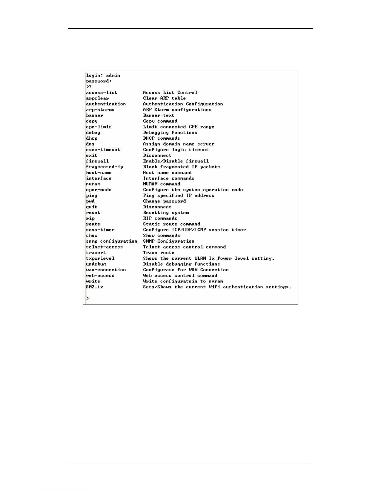
After telnet is established, please type ID and password as shown below.
(ID:admin / Password: cableroot)
Page 29
NWTAP-100 user guide
29
Netwave Proprietary and Confidential
Command format is similar to the CISCO network equipment interface.
“Tab” shortcut key can be used and “?” will display information related to
commands.
Page 30
NWTAP-100 user guide
30
Netwave Proprietary and Confidential
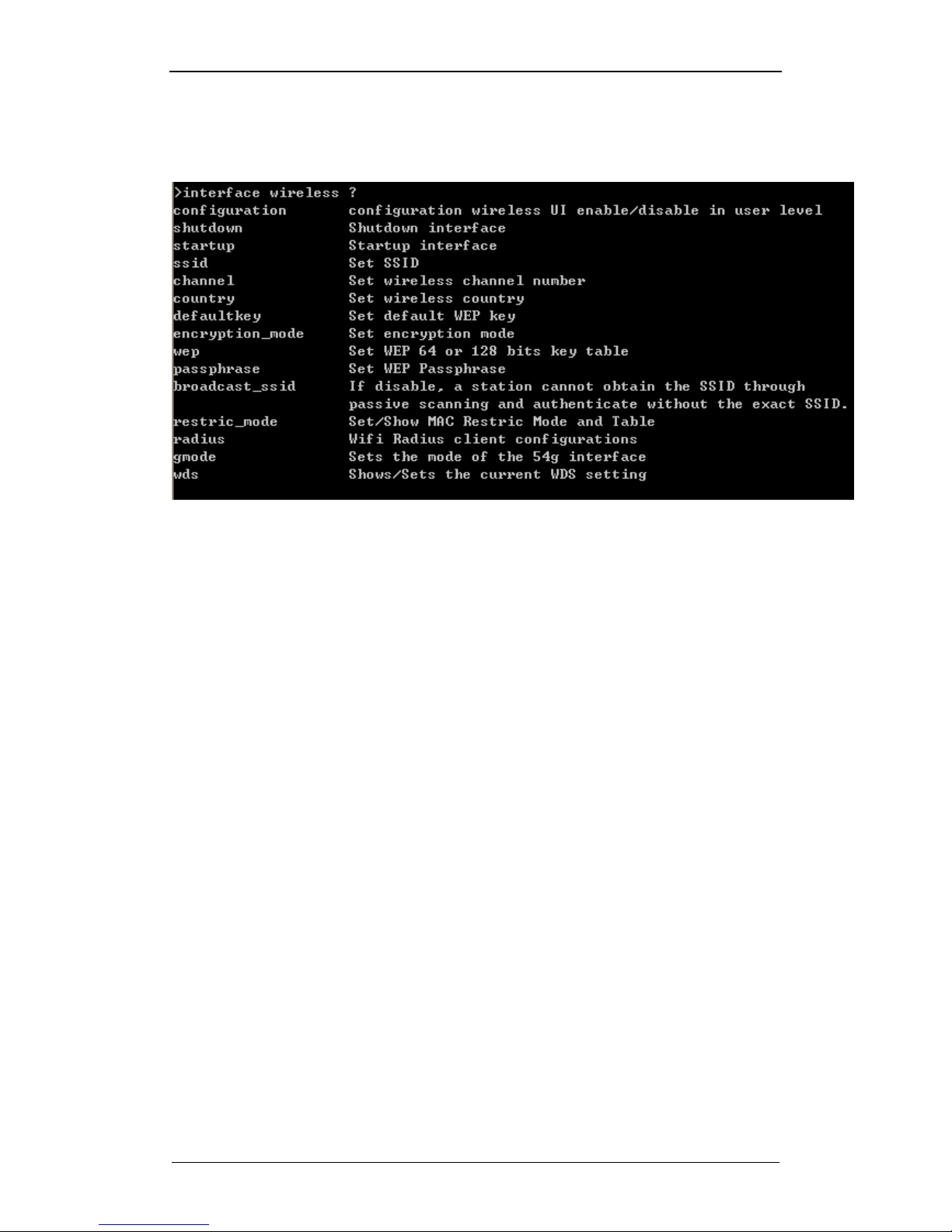
4.9.2. Telnet commands
Commonly used menus related to the wireless interface include the following,
interface wireless shutdown : will disable WLAN
interface wireless startup : will enable WLAN
interface wireless ssid xxx : change the SSID name of WLAN to xxx
interface wireless channel x : change the WLAN RF channel to x
interface wireless restrict_mode disable : disable MAC filtering
interface wireless restrict_mode allow : allow clients on MAC list to have
access
interface wireless restrict_mode deny : deny access to clients on MAC
list
interface wireless restrict_mode add : add MAC address to list
interface wireless restrict_mode delete : delete MAC address from list
Other commonly used menus may include the following.
cpe-limit wireless : will limit the number of clients linked via WLAN (note :
if the cable modem Max CPE value is smaller, the smaller number will
take precedence)
pwd : Telnet id, password can be changed
reset : perform software reset of wireless tap
show : will show the current status of WLAN and cable modem related
parameters. Various submenus are available to provide more detailed
information.
show cpe-info : show clients linked via WLAN
show interface cable downstream : shows cable modem downstream
status
show interface cable upstream : shows cable modem upstream status
telnet-access port : can change the port number for Telnet access.
(default: 64623)
quit : finish the Telnet session
Page 31

NWTAP-100 user guide
31
Netwave Proprietary and Confidential
4.10. SNMP based configuration
4.11. Software upgrade
Page 32

NWTAP-100 user guide
32
Netwave Proprietary and Confidential
5. Troubleshooting
5.1. Troubleshooting for various symptoms
Section Symptom Action
1) Cable modem not online
2) Webui accessible via wireless
1) Verify cable modem MAC is
registered on server
2) Verify that the DOCSIS signal
level into the cable modem is at
an appropriate level. This can be
done by measuring the signal
output from the subscriber
connector and subtracting
3.5dB(12+0.5+1-17) as
explained in section 1.2.1.
3) Verify that there is no signal
quality problem on the HFC
network
4) Try replacing the wireless
tap(possibly cable modem
failure)
Cable modem
1) Cable modem not online
2) Wireless link is now working
1) Verify that AC power is available
on the trunk cable
2) Try replacing the wireless
tap(possibly wireless card
failure)
Wireless LAN 1) Wireless receive strength
close to the wireless tap is >55dBm
1) Check that the antenna cable
connection to the wireless tap
and antenna is tight
2) Try replacing the antenna cable
3) Try replacing the wireless tap
Page 33
NWTAP-100 user guide
33
Netwave Proprietary and Confidential
5.2. Disassembling the wireless tap
It is recommended not to disassemble the wireless tap in any circumstances. The
following material is provided just as a reference.
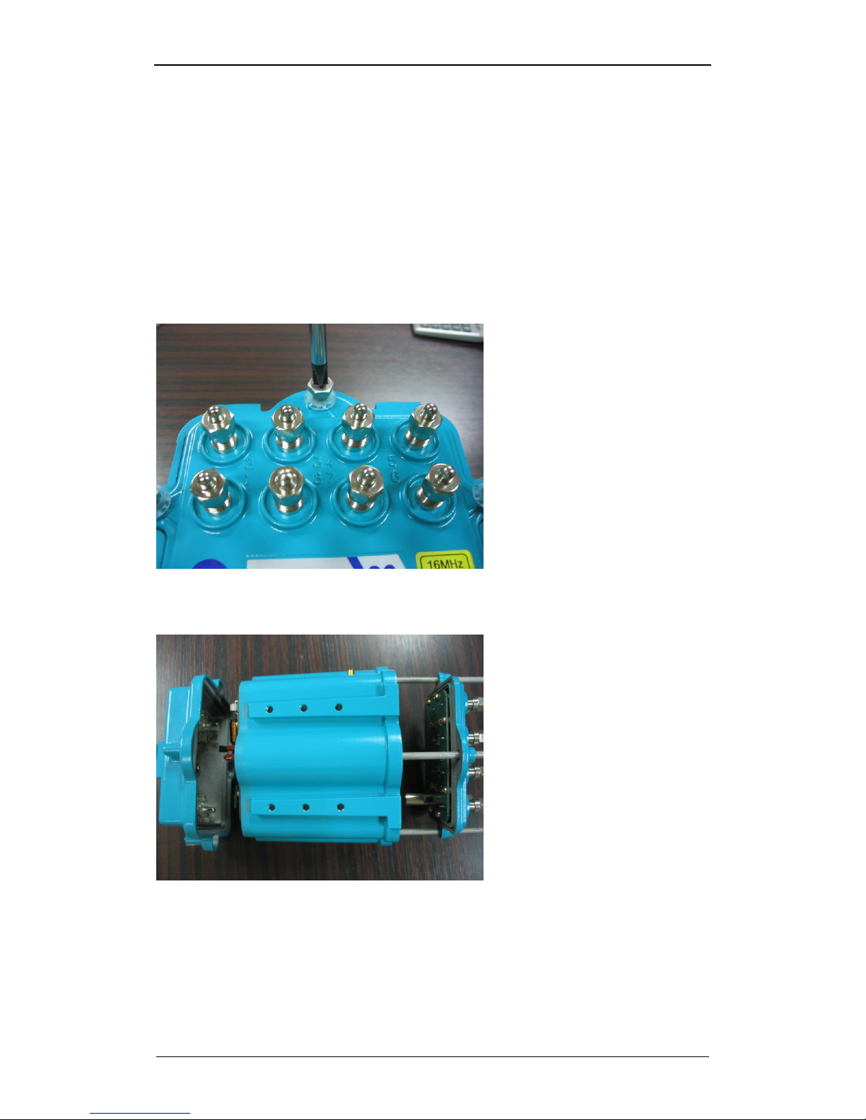
5.2.1. Unscrew the four hexagonal screws that can be found on
the subscriber port side.
These screws hold together the body as well as the top of the tap-off.
Unscrewing the screws will separate the wireless tap into the three
sections as shown in fig. 10
Fig. 10 Unscrew the four main screws
Fig. 11 Separated into three sections after screw removal
Page 34
NWTAP-100 user guide
34
Netwave Proprietary and Confidential
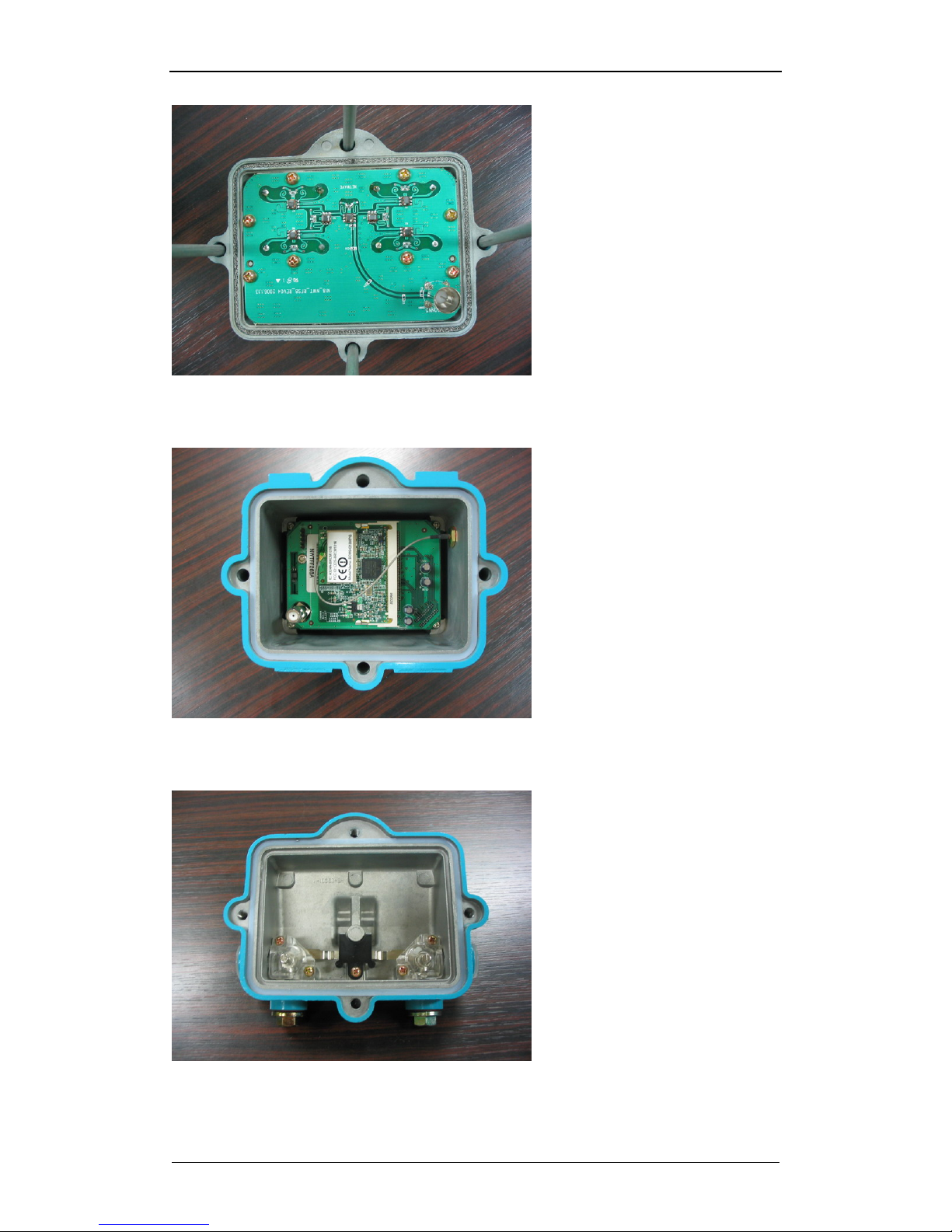
Fig. 12 Splitter circuit for the bottom tap ports
Fig. 13 Cable modem with wireless lan
Fig. 14 Top cover with connection to the trunk cable
Page 35
NWTAP-100 user guide
35
Netwave Proprietary and Confidential
5.2.2. Removing the RF and AC coupling board
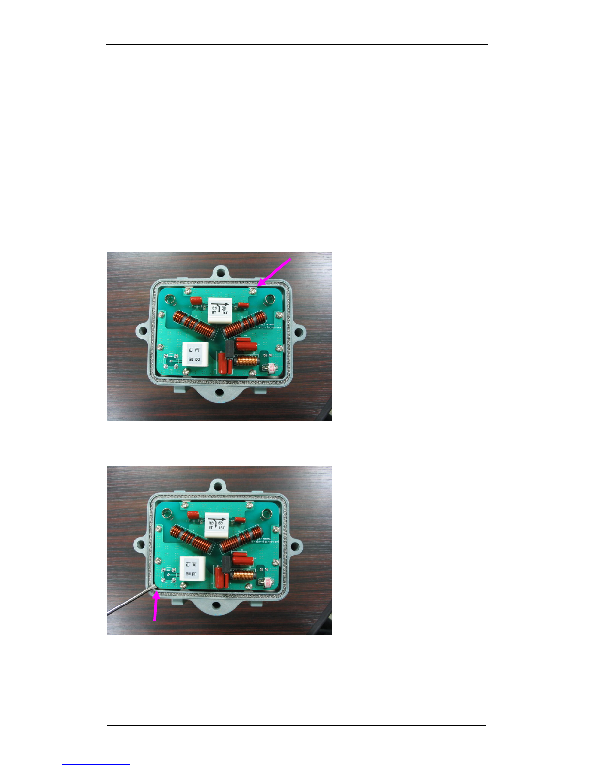
The RF and AC coupling board is situated on the top of the main body
an it can disassembled by removing the eight screws that hold this
board.
After the screws are removed, the board can be removed by lifting the
area where the RF connector is located using a flat head screw driver.
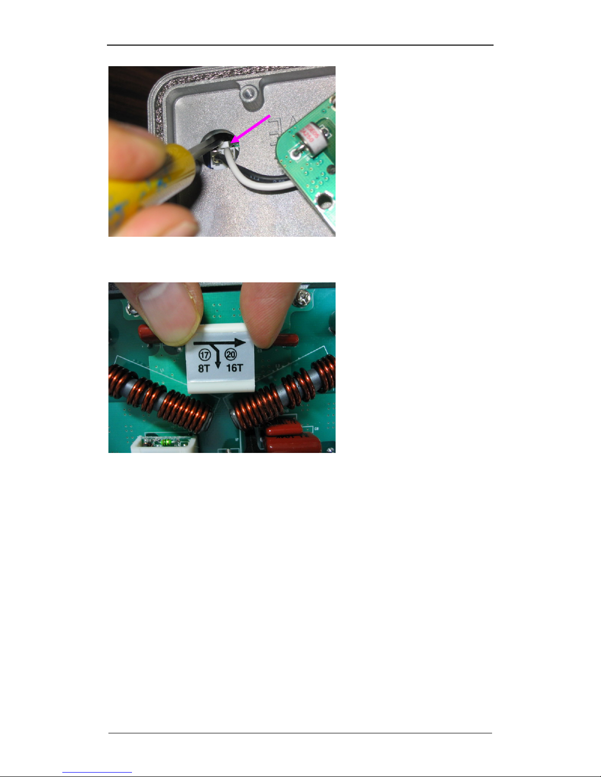
As shown in fig. 16, the AC cable is disconnected from the internal
power module by pressing the side of the plastic flap as shown.
The plug-in coupler can be easily replaced by hand as shown in fig. 18.
The same coupler will have a 3dB difference in coupling ratio between
an 8 port and 16 port design. The module shown in the example will
result in a 17dB tap for 8 ports and 20dB tap for 16 ports.
Fig. 15 Remove the eight screws holding the RF and AC coupling board
Fig. 16 Dislodge the board by lifting the board as shown
Page 36
NWTAP-100 user guide
36
Netwave Proprietary and Confidential
Fig. 17 AC cable disconnection
Fig. 18 Plug-in coupler module can be removed by hand
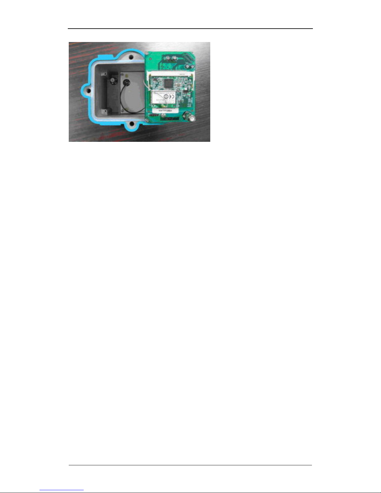
5.2.3. Removing the modem board
The modem board with the wireless lan daughterboard can be removed
by unscrewing the four screws holding the board to the housing.
The bottom of the modem is occupied by a power module that is isolated
with a cover. You can find a DC cable connecting the modem board to
the power module.
Page 37
NWTAP-100 user guide
37
Netwave Proprietary and Confidential
Fig. 19 Modem board unscrewed
Page 38

NWTAP-100 user guide
38
Netwave Proprietary and Confidential
6. Appendix
6.1. Ordering table
6.2. NWTAP-100 specifications
6.2.1. Cable Modem
ITEM Downstream (Receiver) Upstream (Transmitter)
Main IC Broadcom BCM3349
Frequency Range 88MHz ~ 860MHz 5MHz ~ 42MHz
Channel Bandwidth 6 MHz 200K, 400K, 800K, 1.6M,
3.2M, 6.4MHz
Modulation 64QAM/256QAM QPSK, 8 QAM, 16 QAM, 32 QAM,
64QAM, 128 QAM(S-CDMA Only)
Symbol Rate 5.057/5.361Msymbols/sec 160, 320, 640, 1280,
2560,5120 Ksymbols/sec
Bits per Symbol 64QAM: 6 bits
256QAM: 8 bits
QPSK: 2 bits
8QAM: 3 bits
16QAM: 4 bits
32QAM: 5 bits
64QAM: 6 bits
128QAM: 7 bits
Data Rate 30Mbits/sec(64QAM)
43Mbits/sec(256QAM)
0.32 ~ 5.12Mbs (QPSK)
0.48~15.36 Mbps(8QAM)
0.64 ~ 10.24Mbs (16QAM)
0.80~25.60 Mbps(32QAM)
0.96 ~ 30.72Mbps(64QAM,
128QAM)
Input Power -15dBmV ~ +15dBmV
Output Power TDMA:
+8 to +54 dBmV (32QAM, 64QAM)
+8 to +55 dBmV (8QAM, 16QAM)
+8 to +58 dBmV (QPSK)
S-CDMA:
+8 to +53 dBmV (all modulations)
RF Interface
75Ω F-type female connector
Ethernet Interface Standard RJ45 connector
Forward Error Correction RS(122,128) Trellis Reed Solomon
Carrier To Noise Ratio 64QAM: 23.5dB@BER<10
-8
256QAM: 30dB@BER<10-8
6.2.2. Wireless LAN
Item Spec
Main IC Broadcom BCM4318
Wireless standard IEEE 802.11b/g
Data Rate
802.11g: 54, 48, 36, 24, 18, 12, 9, 6 Mbps
802.11b, 11, 5.5, 2, 1 Mbps
Modulation OFDM, CCK, DQPSK, DBPSK
Page 39

NWTAP-100 user guide
39
Netwave Proprietary and Confidential
Operating
Frequencies/Operating
Channels
2.4GHz~2.497GHz (14 channels for Japan)
2.4GHz~2.472GHz (13 channels for Europe, Korea)
2.4GHz~2.462GHz (11 channels for North America)
RF Output Power
20 dBm maximum (>17dBm output from antenna
connector)
Antenna diversity Antenna diversity is supported
Antenna connector SMA (female)
Antenna type Various types supported
Attestation
FCC ID : QWFNWTAP-100
Product : Wireless Tap
Model : NWTAP-100
Wd don’t provide any controls or software to allow operation outside the USA
frequency bands when this product is sold within the USA.
6.2.3. Authentication & Gateway
Item Spec
Authentication MAC, EAP-MD5, WPA2
Client count Maximum client count limiting
Accounting Radius accounting
Filters mac, ip and port filtering
DHCP DHCP server
Forwarding Port forwarding and triggering
DMZ DMZ host
Firewall Parental control and firewall
VPN IPSec & PPTP passthrough
Router RIPv2
Page 40

NWTAP-100 user guide
40
Netwave Proprietary and Confidential
6.2.4. TAP
6.2.5. General
Item Spec
Management HTTP, Telnet and SNMP
Upgrade Remote software upgrade
Feeder power input
range
60~130V AC
Power consumption <7watts
19x12x15cm(for 8 tap)
Size
20x14x16cm(for 16 tap)
Weight 2.21 Kg
Temperature : -35°C ~ + 60°C
Environment
Humidity : 5% ~ 85%
Item Unit Spec
Comments
Frequency range MHz 5.75 ~ 870MHz
Tap off value dB 11 14 17 20 23 26 29
- 4.9 3.5 2.7 2.0 1.9 1.8
Down
8-tap dB
-
3.9 2.0 1.4 1.1 1.1 1.1
Up
- 4.9 3.5 2.7 2.0 1.9
Down
Max
insertion
loss
16-tap dB
- 3.9 2.0 1.4 1.1 1.1
Up
- 23 26 27 30 33 36
Down
8-tap dB
- 25 25 28 31 31 31
Up
- 23 26 27 30 33
Down
Min reverse
isolation
16-tap dB
- 25 25 28 31 31
Up
Tap off variation dB
< ±1.5
Subscriber port coupling dB
> 20
Reflection loss dB
> 16 (input, output, subscriber port)
Frequency response dB
< ±0.75 (tap-off value)
Hum modulation dB
> 65
Current capacity A
> 10A
Page 41

NWTAP-100 user guide
41
Netwave Proprietary and Confidential
6.3. FCC warning
This equipment generates uses and can radiate radio frequency energy and, if not
installed and used in accordance with the instructions, may cause harmful
interference to radio communications. However, there is no guarantee that
interference will not occur in a particular installation.
If this equipment does cause harmful interference to radio or television reception
which can be determined by turning the equipment off and on, the user is
encouraged to try to correct the interference by one or more of the following
measures.
z Reorient or relocate the receiving antenna.
z Increase the separation between the equipment and receiver.
z Connect the equipment into an outlet on a circuit different from that to
which the receiver is connected.
z Consult the dealer or an experienced radio, TV technical for help.
z Only shielded interface cable should be used.
Finally, any changes or modifications to the equipment by the user not expressly
approved by the grantee or manufacturer could void the users’ authority to operate
such equipment.
1) Sales
The device cannot be sold retail to the general public or by mail order. It is only sold
to professional dealers or service operators.
2) Installation
This device requires a professional installation by someone trained in CATV HFC
networks as well as WiFi equipment.
The NWTAP-100 is mounted on strands that are located high on poles. The input
and output connectors need to be connected to 12C coaxial cables which feed CATV
signals as well as AC powering. Therefore, it is dangerous for an untrained person to
install this equipment. Furthermore, a person trained in WiFi should support the
installation work so that the optimal reception of WiFi signals at intended locations
can be achieved.
3) Application
The NWTAP-100 is not intended for personal use. This equipment should be
installed and maintained by a service operator who will provide Internet access
through this equipment.
 Loading...