

Page 1
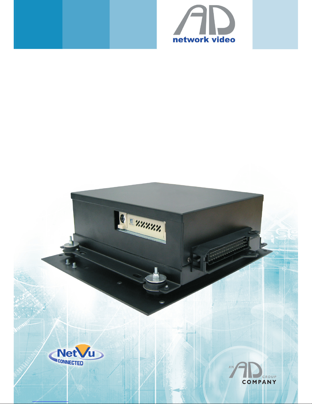
TransVu
Installation Guide
Page 2

AD network video ©2011
2
TransVu
Contents
Introduction .......................................................................... 3
Installation ............................................................................ 4
Cable Connections ............................................................. 10
Example Installations ......................................................... 19
Appendix A - Recommended Tools and Spares ................. 22
Appendix B - Telemetry ...................................................... 23
Appendix C - Technical Specication ................................. 24
Page 3

AD network video ©2011
3
TransVu
Introduction
TransVu is a Digital Video Recorder specically designed for transport applications. With a ruggedised
design to withstand the often heavy vibrations generated by vehicles, TransVu is ideal for mobile
surveillance in all types of vehicle – such as taxis, vans, buses, trains and heavy goods vehicles.
Part of the NetVu Connected product range the TransVu is fully network capable and supports the Internet
standard TCP/IP protocol. As the TransVu is a mobile product the unit can be accessed via wireless LAN
or GSM / GPRS / CDPD. Supporting upto eight video inputs, two audio channels, panic alarm handling and
intelligent power handling the TransVu is a powerful transit recorder.
System Documentation
The Installation and Operation of the TransVu are detailed in the manual suite which consists of:
• Quick Start Guide - Initial steps to get the TransVu up an running to basic operation.
• Installation Guide - Full instructions to install the TransVu unit.
• Conguration and Operation Guide - Full conguration documentation for the TransVu.
Page 4
AD network video ©2011
4
TransVu
Installation
This section is seperated into Physical Installation (tting the baseplate, shock absorbers etc.) and System
Installation (cable connections, etc.)
Physical Installation
Product Orientation
Although the TransVu can be mounted horizontally or vertically, it is recommended that it should be
mounted horizontally using the supplied mounting kit, with the multipole plug facing the rear of the vehicle.
This ensures the accelerometer gives the correct reading.
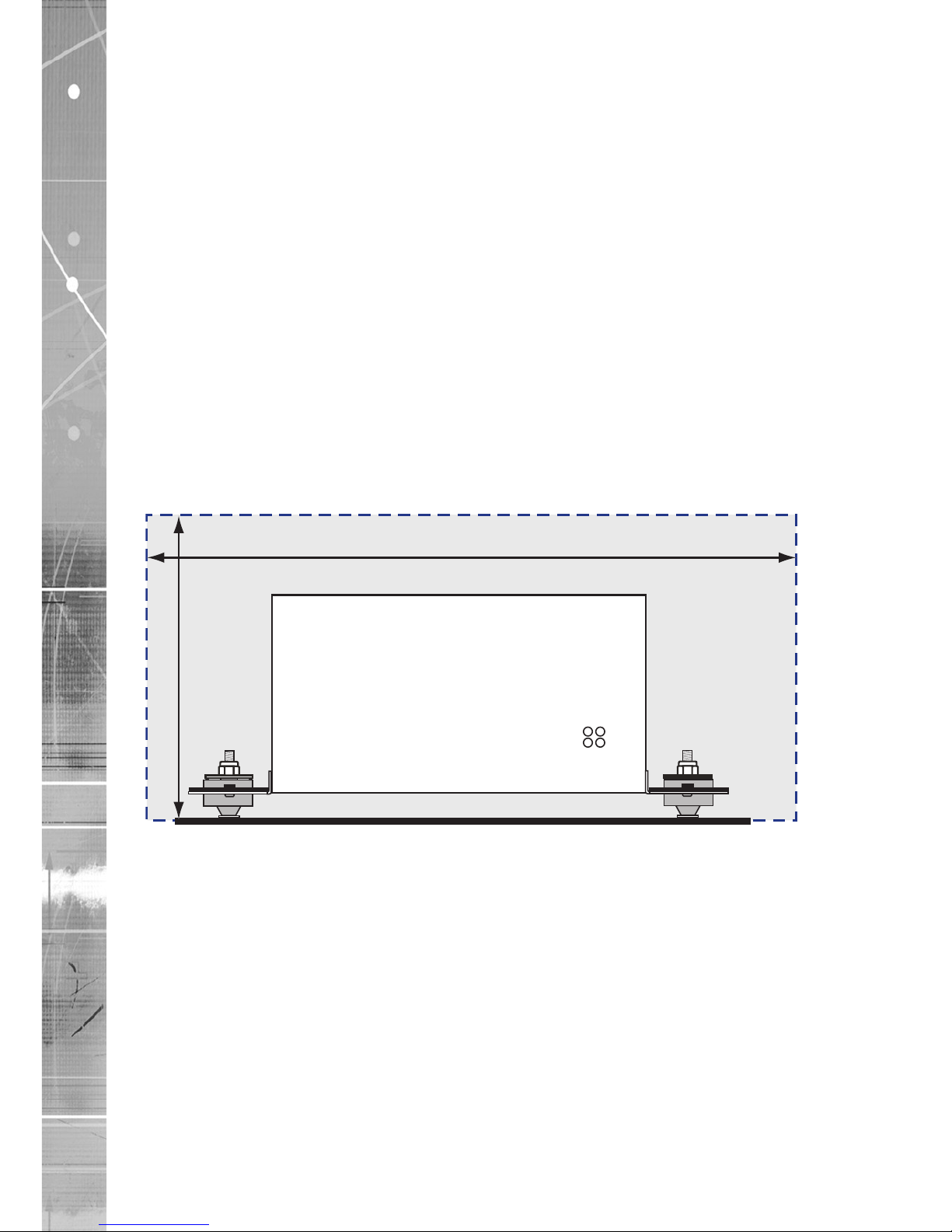
It is important that sufcient space be provided for the unit and cable connector.
Installation space required for the TransVu
The TransVu is xed to the vehicle via a mounting plate.
It should be mounted as low as possible within the vehicle, on a secure base free from resonance and
secondary vibrations.
The TransVu is xed to the mounting plate via four shock absorbing xings. This dramatically reduces the
vehicle vibrations and enables the TransVu to operate in harsh shock environments.
Vibration will cause the TransVu to move on the shock mounts. Therefore a reasonable clearance must be
allowed around the unit.
A suggested tment area of 350mm (13fl”) x 380mm (15”) x 140mm (5” ) is recommended.
140mm
(5”)
350mm
(13”)
Page 5
AD network video ©2011
5
TransVu
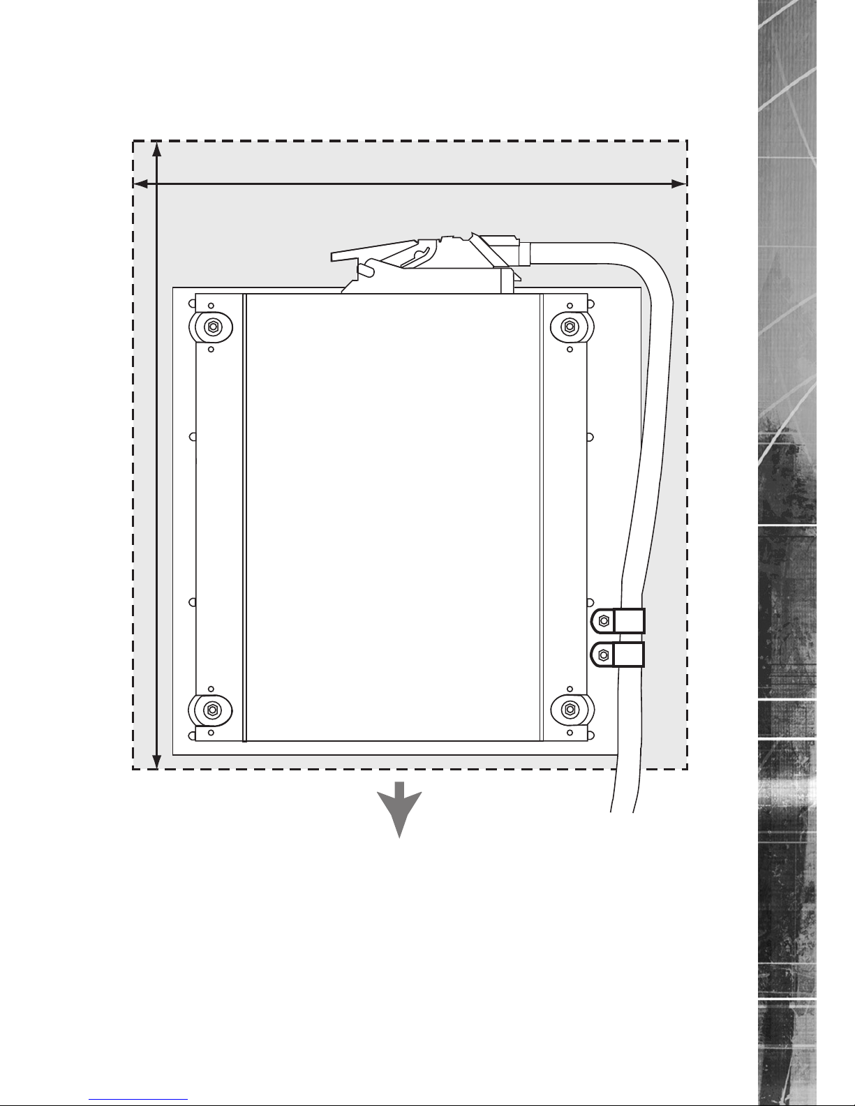
Care in feeding cables
Ensure the cables feeding the multipole plug are clamped to avoid any vibration being transmitted along
them to the unit. Cable clamp posts are provided on the baseplate. The two clamps (highlighted) must be
used to prevent the cable vibrating loose.
380mm
(15”)
350mm
(13”)
FWD
Notes on installation space
Additional space is required around the plug to accomodate the disconnection of the cable from the unit.
Page 6
AD network video ©2011
6
TransVu
Mounting the Baseplate
The TransVu baseplate should be secured to the vehicle using appropriate nuts, bolts and shakeproof
washers. The baseplate should be mounted horizontally. Ensure the correct orientation of the TransVu once
it is mounted on the baseplate. The Transvu multipole socket should face the rear of the vehicle, at the top
of the base plate, and the cable clamp should be on the right hand side.
These details cover installation using the Rev B metalwork.
Mounting restriction for correct G-force implementation
If the G force detectors are tted in the TransVu, the baseplate must be correctly orientated within the
vehicle.
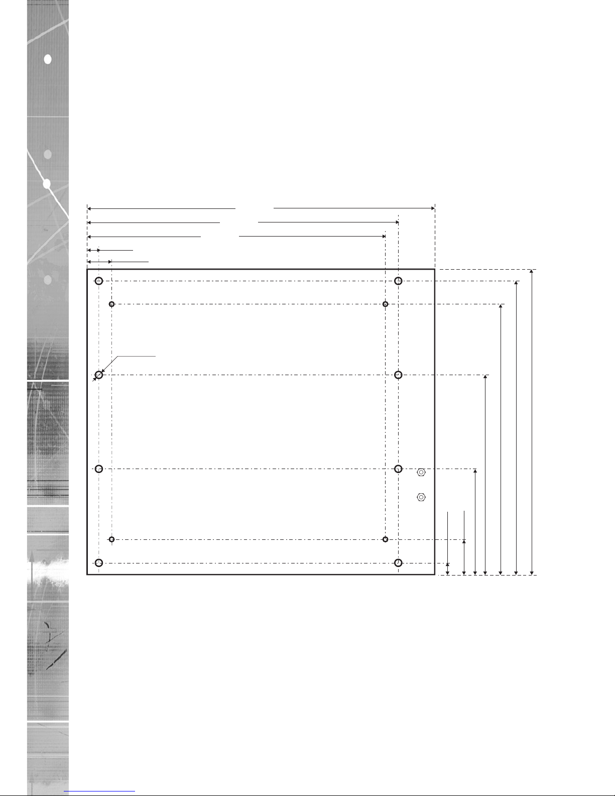
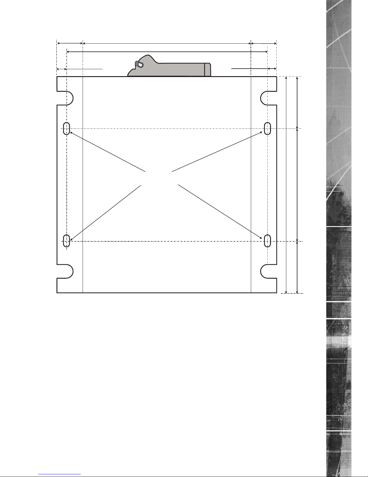
Baseplate dimensions & measurements:
6mm (x8)
296mm
260mm
250mm
230mm
170mm
90mm
36mm
10mm
265mm
254mm
10mm
21mm
Page 7
AD network video ©2011
7
TransVu
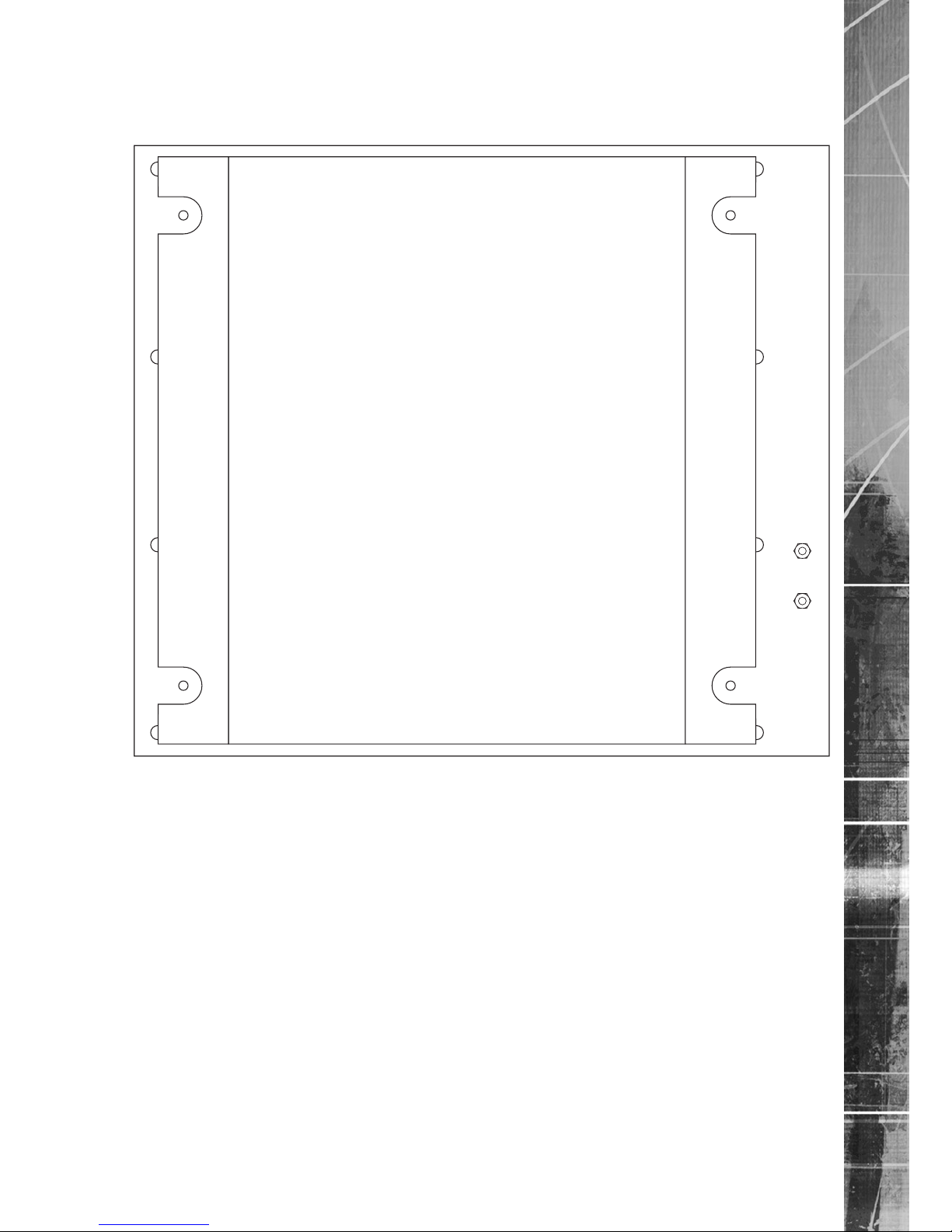
TransVu top view dimensions
30mm
11mm
11mm
195mm
250mm
130mm60mm 60mm
Holes
7mm x 13mm
233mm
30mm
Note: Early metalwork used smaller ange mounts for bolt xing suspension. The 7mm x 13mm holes
were aligned on a 145mm x 215mm square relative to the centre of the unit.
Page 8
AD network video ©2011
8
TransVu
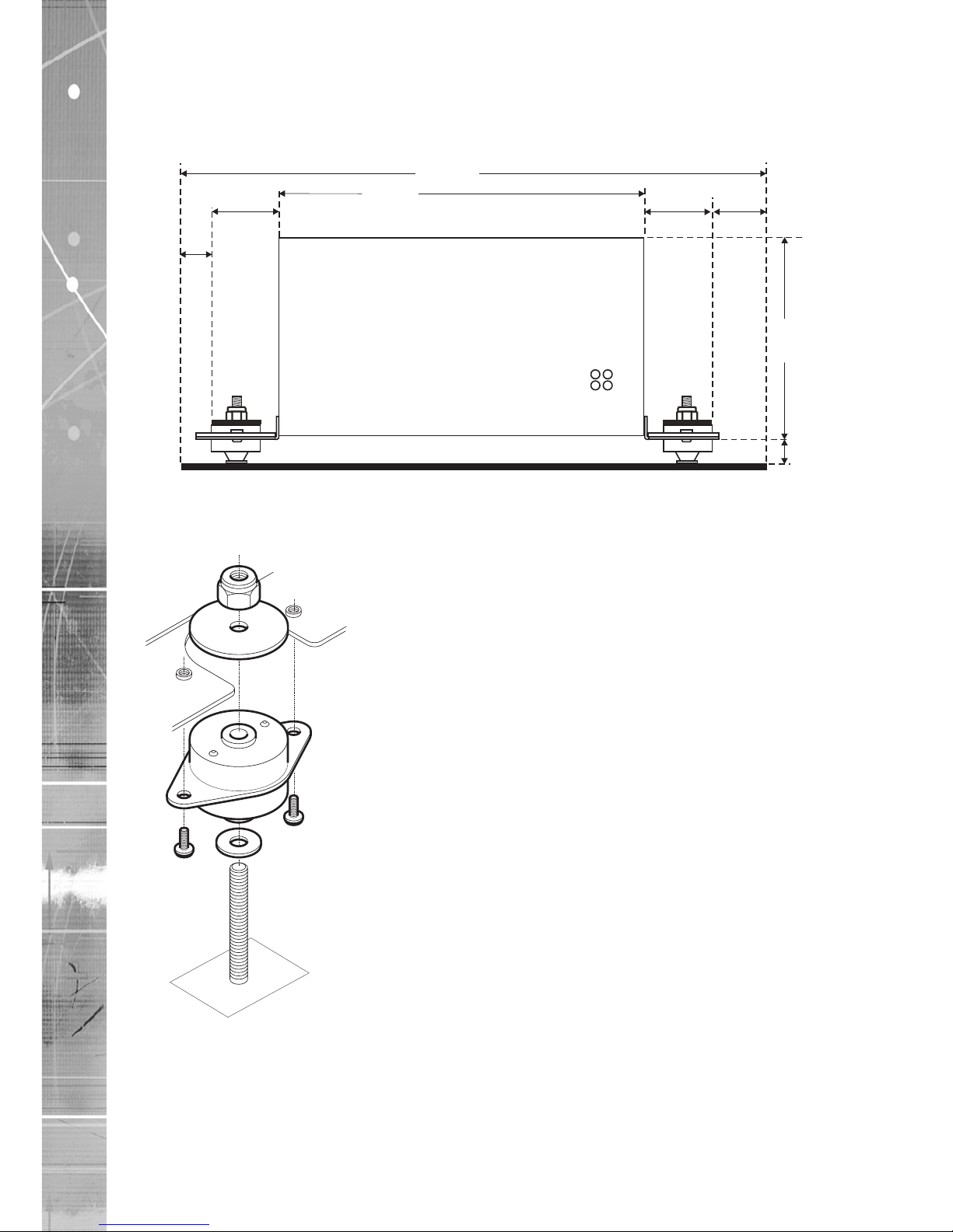
TransVu end view dimensions:
Note: The measurement from the baseplate to the base of the TransVu is a measured 18mm (¾ inch)
when the assembly is static. When the assembly is subject to vibration this measurement will alter
dynamically.
296mm
195mm
30mm
30mm
30mm
10mm
90mm
18mm
(static)
Fitting shock absorbers to the unit.
This procedure to mount the shock absorbers to the TransVu must be adhered to, this will ensure minimum
movement due to vibration:
Page 9
AD network video ©2011
9
TransVu
Fitting the TransVu to the baseplate
The Transvu multipole socket should face the rear of the vehicle, at the top of the base plate, with the cable
clamp on the right hand side.
Note: The cable clamp is provided to reduce vehicle vibration being transmitted from the cable loom
through to the TransVu. Ensure that the cable loom between the clamp and the multipole socket
does not touch any part of the vehicle.
Page 10
AD network video ©2011
10
TransVu
Cable Connections
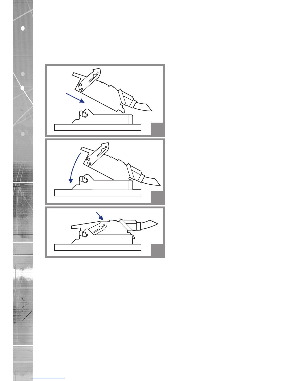
Multipole Connector
All connections to the Transvu unit are made via a 55 way female multipole connector.
The connector is mated to the TransVu as follows:
1
2
3
Page 11
AD network video ©2011
11
TransVu
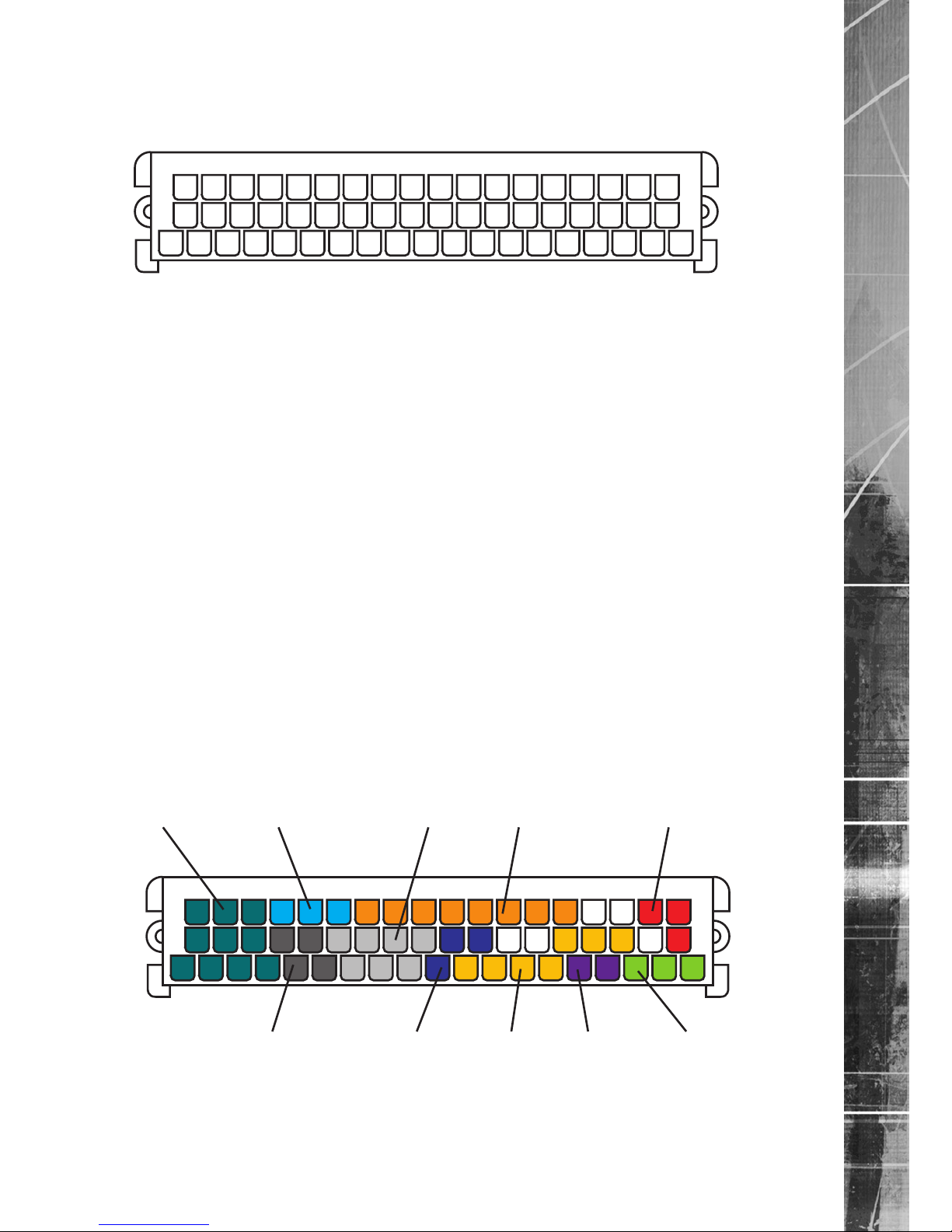
Multipole Connector Layout
All connections to the Transvu unit are made via a 55 way multipole connector.
This view looks into connector mounted on the TransVu.
1
20
38405055
3037
1019
Pin Signal Pin Signal Pin Signal
1 Chassis Gnd 20 Chassis Gnd 38 Power In
2 Heater Supply ◊ *** 21 Video Out ◊ ** 39 Switched power Out ◊ *
3 Spot Monitor Out ◊ ** 22 RXD COM 1 40 Audio Gnd
4 Status Power 23 Chassis Gnd 41 Audio Out ◊ **
5 Status LED 24 DCD COM 1 42 Chassis Gnd
6 DTR COM 1 25 RXD COM 5 43 RXD COM 2
7 CTS COM 1 26 TXD COM 5 44 RTS COM 2
8 RTS COM 1 27 RXD COM 6 45 CTS COM 2
9 TXD COM 1 28 TXD COM 6 46 DTR COM 2
10 Chassis Gnd 29 Chassis Gnd 47 DSR COM 2
11 Alarm I/P 5 30 Alarm I/P 6 48 DCD COM 2
12 Alarm I/P 3 31 Alarm I/P 4 49 TXD COM 2
13 Alarm I/P 1 32 Alarm I/P 2 50 Audio Gnd
14 Ethernet TD + 33 Ethernet TD - 51 Audio Input 2
15 Ethernet RD + 34 Ethernet RD - 52 Audio Input 1
16 Video Gnd 35 Camera 1 53 Camera 6
17 Camera 2 36 Camera 3 54 Camera 7
18 Camera 4 37 Video Gnd 55 Camera 8
19 Camera 5
* Pin 39 carries the Input voltage and is not a regulated 12V supply.
** For future expansion
*** For specic build
◊ Rev D board only
Multipole General Diagram
Cameras Audio Alarm Inputs COM2 Port Power
Network COM6 Port COM1&5 Ports LEDs Spot Monitor
Page 12
AD network video ©2011
12
TransVu
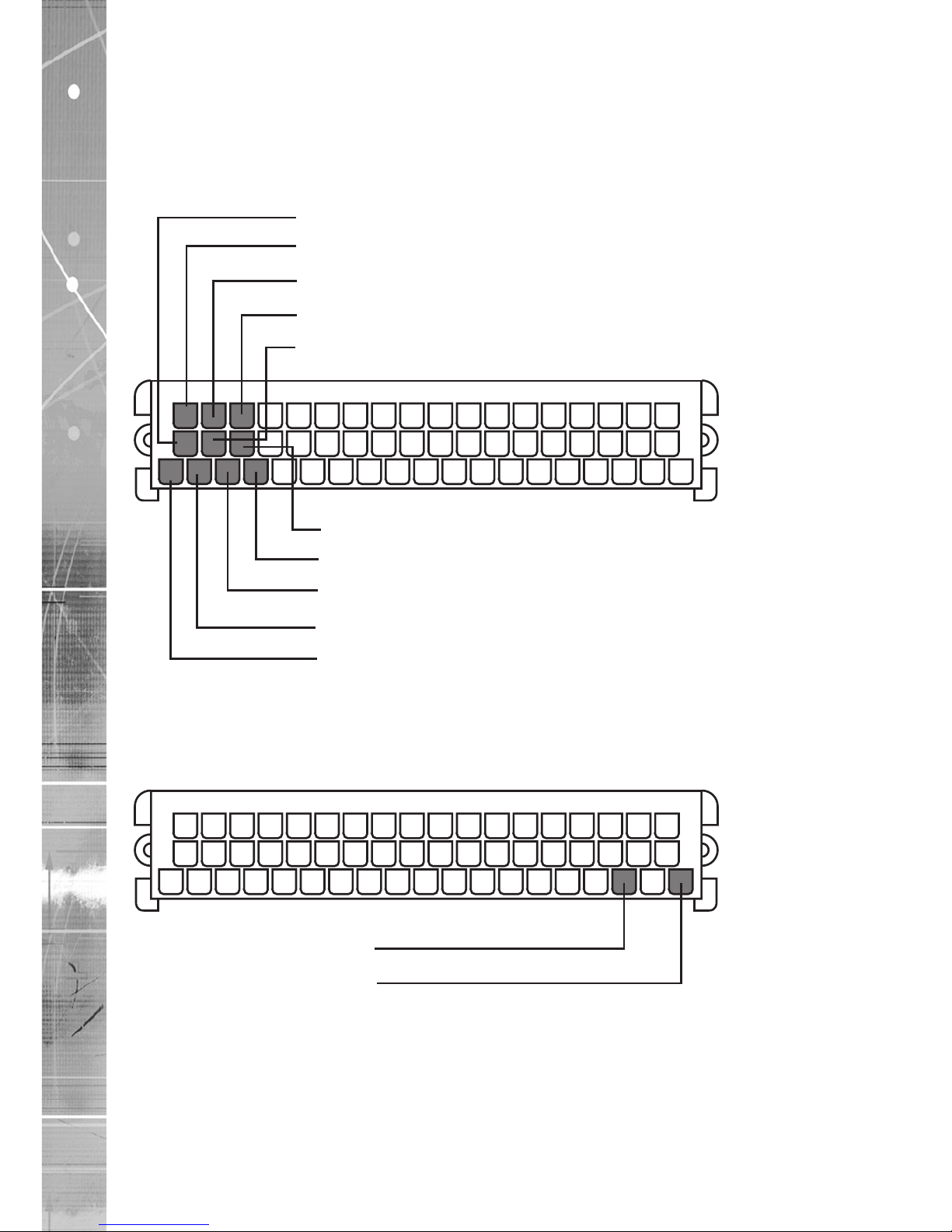
Connecting Cameras
Signal type Unbalanced, ground common to chassis
Signal level 1 volt peak to peak
Signal termination 75 ohms, switchable in software
Recommended cable Coaxial, 75 ohm impedance, 90% copper braid, copper multicore
central conductor.
1
20
38405055
3037
1019
37. Vid Gnd (Cam 8,7,6,3)
55. Cam8 Vid In
54. Cam7 Vid In
53. Cam6 Vid In
36. Cam3 Vid In
35. Cam1 Vid In
16. Vid Gnd (Cam 1,2,4,5)
17. Cam2 Vid In
18. Cam4 Vid In
19. Cam5 Vid In
Note: Care should be taken to ensure all camera cable screens are rmly bonded together and securely
connected to multipole connector pins 16 & 37.
Connecting a Spot Monitor
The spot monitor connects to the BNC connector wired into the loom.
1
20
38405055
3037
1019
3. Spot Monitor Signal
1. Spot Monitor Ground
Page 13
AD network video ©2011
13
TransVu
Connecting Audio
Signal type Unbalanced, common analog ground
Input type Microphone or line input selectable by hardware link
Signal levels Mic input 25mv to 500mv P/P input
Impedance 1Kohm
Line input Impedance 50mv to 1000mv
Powered Microphone Selectable by hardware link: Please contact AD network video
Technical Support for information
Recommended cable Single core screened audio cable
Note: AGC and line/mic input selection is congured through webpages.
1
20
38405055
3037
1019
52. Audio in 1
51. Audio in 2
50. Audio Gnd
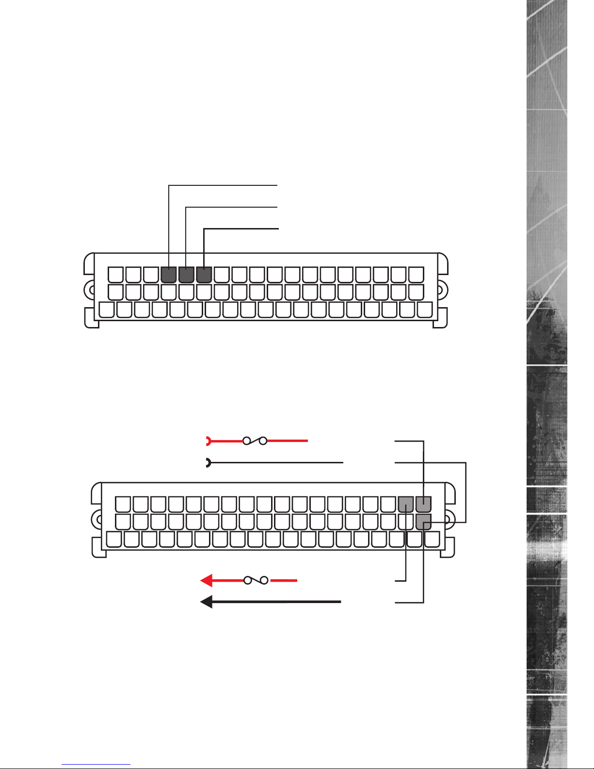
Connecting vehicle power
TransVu is designed to run on vehicles with a negative earth or negative ground system.
When the unit is running the power input is reflected on the power output pin, being relay contacts switched
under software control.
This allows ancillary equipment such as cameras etc. to be powered down automatically preventing
unnecessary drain on the vehicle battery.
+
-
Fuse
+
-
Fuse
1
20
38405055
3037
1019
39. Pwr Output
20. Gnd
38. Pwr Input
20. Gnd
From Vehicle
Power Supply
To Ancilliary
Equipment
Page 14
AD network video ©2011
14
TransVu
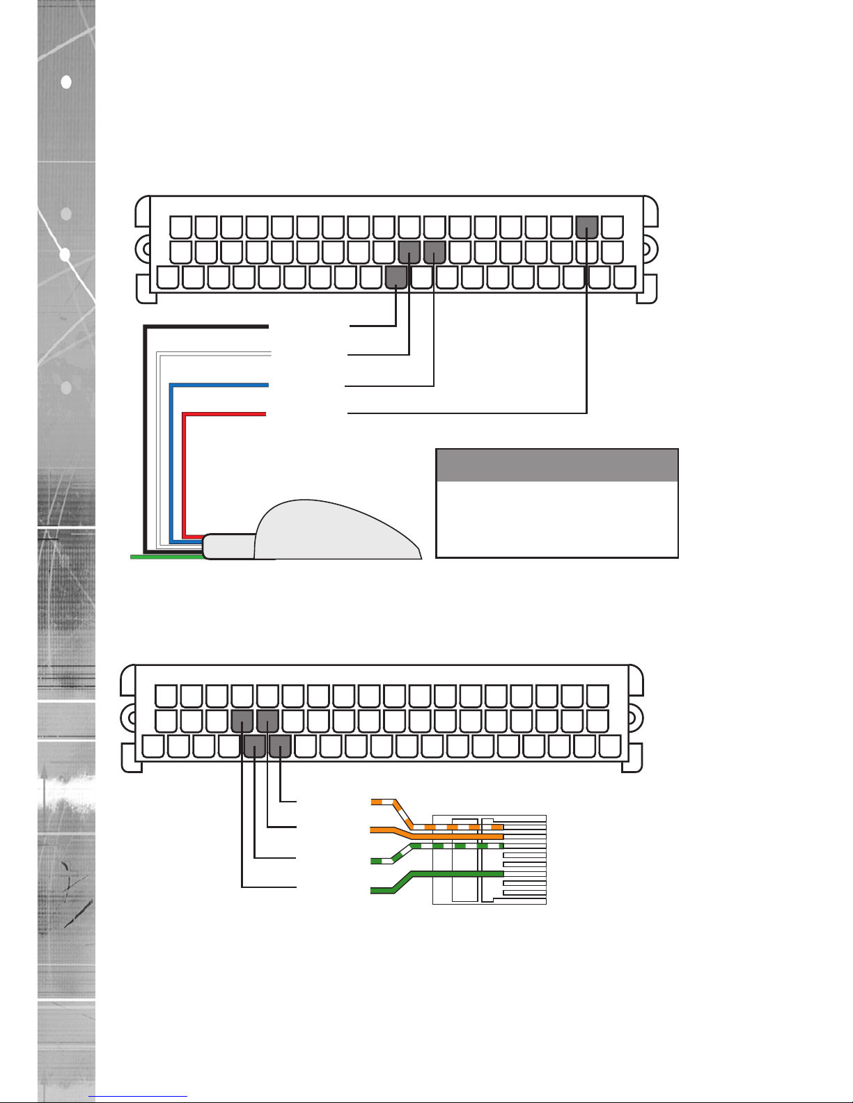
Connecting a GPS
Signal type RS232
Signal level 4800 baud serial 8 bits, no parity, 1 stop bit.
(must be set in webpages to enable operation)
Recommended GPS Any suitable RS232 GPS I/F providing NMEA
Cable 5 core supplied with GPS unit
GPS
1
20
38405055
3037
1019
10. Gnd
28. TXD
27. RXD
39. PWR
Switched Supply from TransVu
Cable
Black
Blue
White
Red
Green
GPS
Signal
GND
RXD
TXD
+VE
RXDS
Pin
No
10
28
27
39
Not Used
TransVu
Signal
GND
TXD
RXD
PWR OUT
Contact Technical Support for a list of recommended compatible GPS Units.
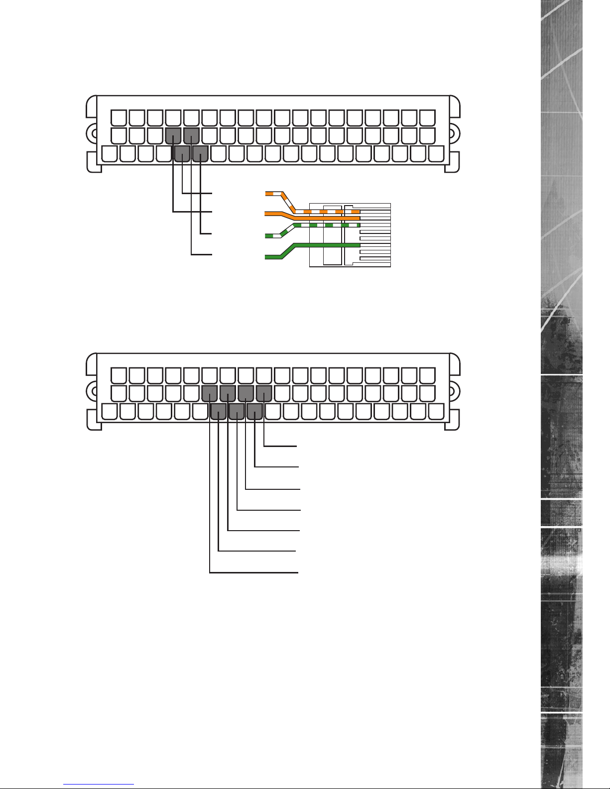
Connecting to a Network Hub
This wiring conguration uses an RJ45-11 connector to plug into a network hub on an ethernet network.
Recommended cable CAT 5
1 - White/Orange TX+
2 - Orange TX3 - White/Green RX+
4 - Blue
5 - White/Blue
6 - Green RX7 - White/Brown
8 - Brown
1
20
38405055
3037
1019
14. TD+
33. TD-
15. RD+
34. RD-
Page 15
AD network video ©2011
15
TransVu
Connecting to a PC Network port
This wiring conguration uses an RJ45-11 connector to plug directly into a PC network port.
Recommended cable CAT 5
1 - White/Orange TX+
2 - Orange TX3 - White/Green RX+
4 - Blue
5 - White/Blue
6 - Green RX7 - White/Brown
8 - Brown
1
20
38405055
3037
1019
15. TD+
34. TD-
14. RD+
33. RD-
Alarm Inputs
Six analog alarm inputs are provided, one of which defaults to ignition sense when power management is
enabled (Pin 11, Alarm 5). The remaining ve are software congurable for analogue or digital operation.
Input 6 (Pin 30) can additionally be used for pulse counting, measuring road or engine speed.
See the Example installations for information on conguring vehicle data logging.
1
20
38405055
3037
1019
29. Alarm Gnd
11. Alarm 5
30. Alarm 6
12. Alarm 3
31. Alarm 4
13. Alarm 1
32. Alarm 2
Alarm 1 - Door contact - Typically to indicate when the main door is open.
Alarm 2 - Panic button - Generally operated by the driver when under duress.
Alarm 3
Alarm 4 - To detect low oil pressure.
Alarm 5 - Ignition sense - To detect ignition switch off and power down after a set period of time. A
suitable pull up resistor must be included if a passive device is connected.
Alarm 6 - Tacho / speedo sensor - To log engine revs or vehicle speed.
Page 16
AD network video ©2011
16
TransVu
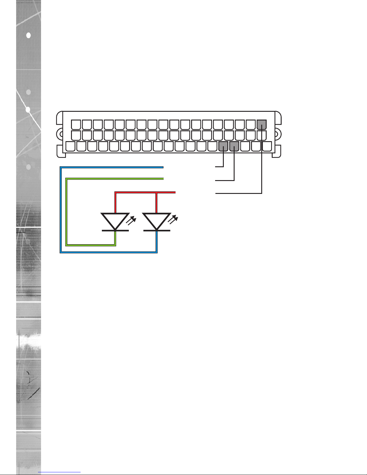
Connecting Indicator LEDs
Provision is made for external Indicator LEDs.
Status Power
This LED illuminates to indicate the unit has power.
From Application 3.1 (5.9) this LED will be turned off if:
Any camera selected to be recorded fails
Any camera selected to be viewed fails
Status Recording
The “Status LED 2” LED flashes when the disk drive is written to, to indicate recording.
1
20
38405055
3037
1019
5. Status LED
4. Status Pwr
38. Pwr In
Status
LED 2
Status
Power
Page 17
AD network video ©2011
17
TransVu
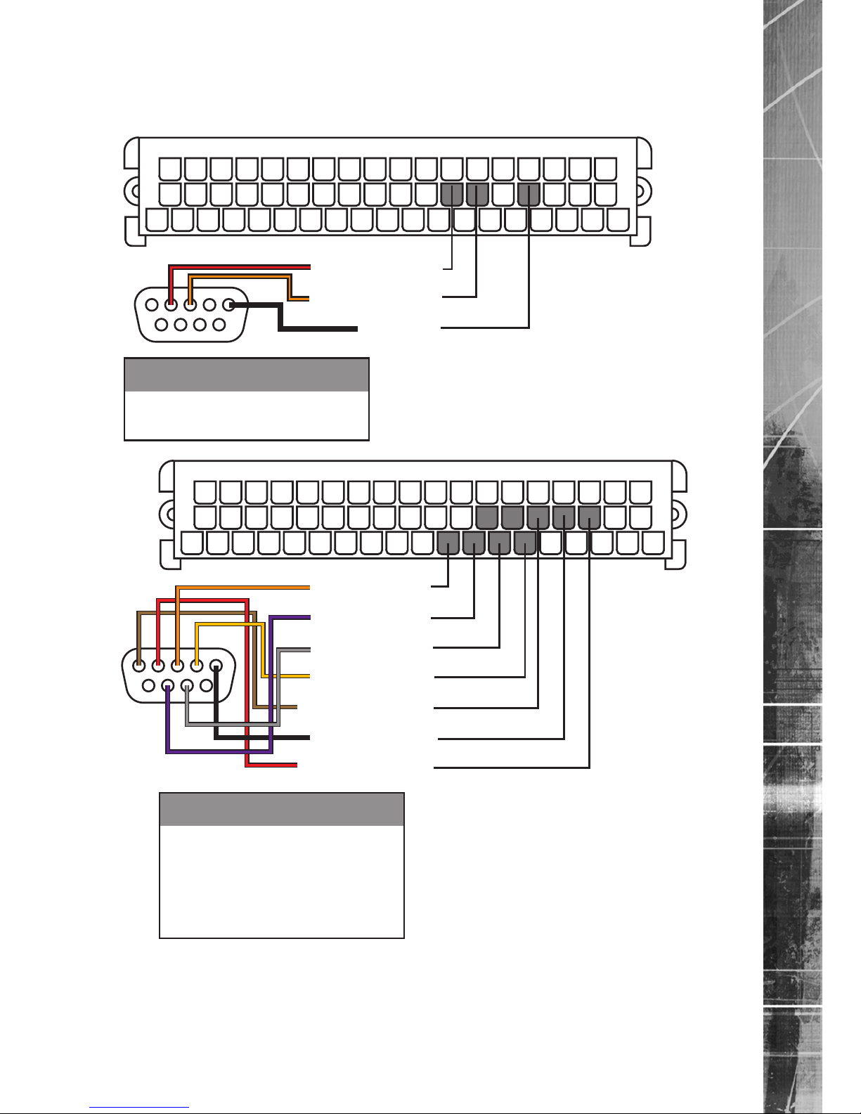
Connecting COM 5 and COM 1 serial ports
Connectors are Male 9 pin D types seen from the pin (connector) side.
By default the COM 5 port will be assigned for DEBUG.
26. COM5 TXD
25. COM5 RXD
23. GND
1
20
38405055
3037
1019
Cable
Red
Orange
Black
Signal
RXD
TXD
GND
Pin
No
25
26
23
COM5
Pin
2
3
5
5
1
6
9
9. COM1 TXD
8. COM1 RTS
7. COM1CTS
6. COM1DTR
24. COM1DCD
23. GND
22. COM1RXD
1
20
38405055
3037
1019
Cable
Brown
Red
Orange
Yellow
Black
Purple
Grey
Signal
DCD
RXD
TXD
DTR
GND
RTS
CTS
Pin
No
24
22
9
6
23
8
7
COM1
Pin
1
2
3
4
5
7
8
5
1
6
9
Page 18
AD network video ©2011
18
TransVu
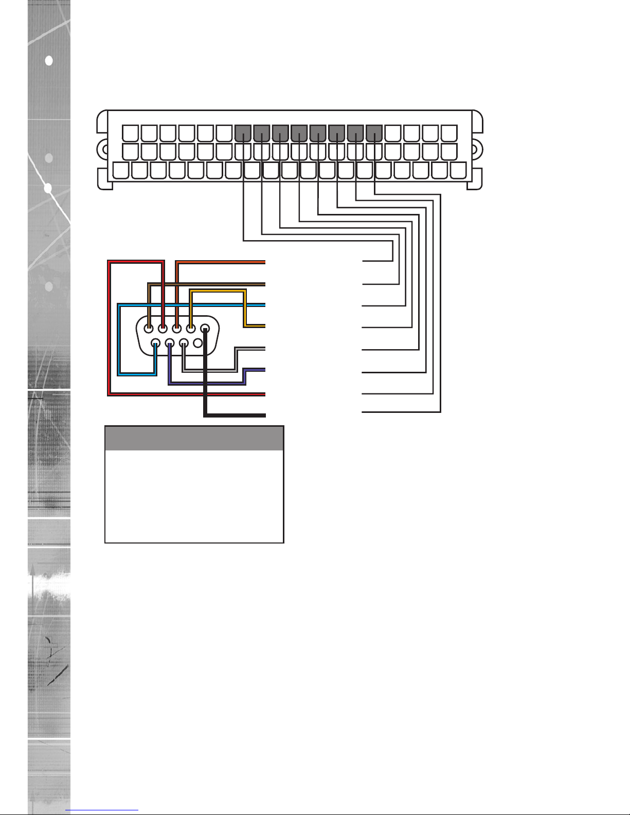
Connecting the COM 2 serial port
Connectors are Male 9 pin D types seen from the pin (connector) side.
By default the COM 2 port will be assigned for PPP connections (SMS / GMS units).
In this conguration the 9 pin D type male connects directly to the DCE equipment
49. COM2 TXD
48. COM2 DCD
47. COM2 DSR
46. COM2 DTR
45. COM2 CTS
44. COM2 RTS
43. COM2 RXD
42. GND
1
20
38405055
3037
1019
Cable
Brown
Red
Orange
Yellow
Black
Blue
Purple
Grey
Signal
DCD
RXD
TXD
DTR
GND
DSR
RTS
CTS
Pin
No
48
43
49
46
42
47
44
45
COM2
Pin
1
2
3
4
5
6
7
8
5
1
6
9
Page 19
AD network video ©2011
19
TransVu
Example Installations
Taxi – Simple implementation.
American Schoolbus
Vehicle Data Logging
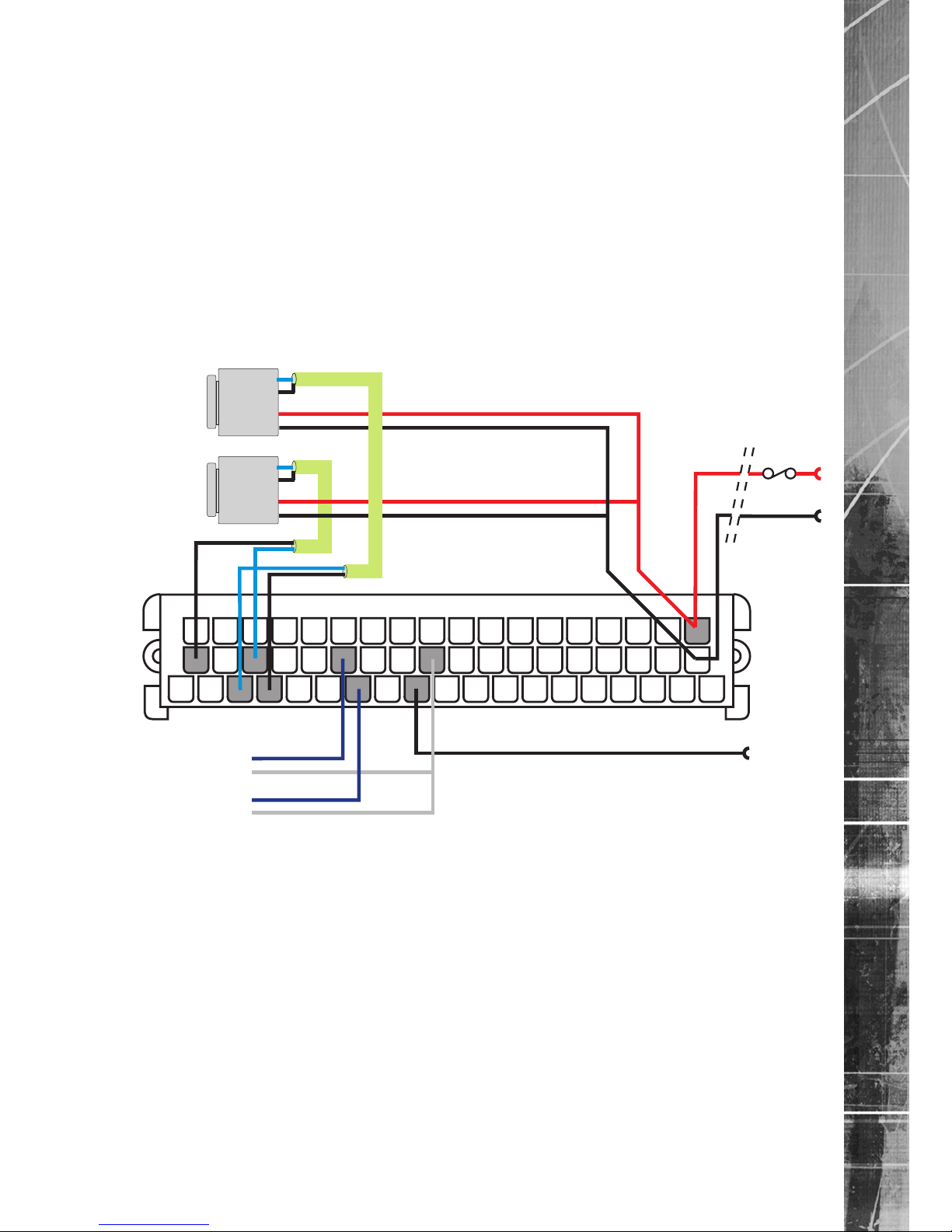
Example wiring - Taxi
This is a simple implementation using two cameras.
Two alarm inputs are wired up, one indicates that the electronic door safety locking is operational and the
other provides a panic button for the driver.
The vehicle ignition sensor will automatically power down the unit shortly after the ignition is switched off.
It also cuts power to the cameras to ensure the vehicle battery is not attened. Recorded images can be
viewed on the TransVu playback station.
1
20
38405055
3037
1019
Passenger
Camera
Driver
Camera
Door ‘locked’
contacts
Panic alarm
button
Switched Power from TransVu
From vehicle
power supply
Fuse
From vehicle ignition line
+
-
Video out
Video Gnd
+Vrs Supply
Supply Gnd
Video out
Video Gnd
+Vrs Supply
Supply Gnd
-
Page 20
AD network video ©2011
20
TransVu
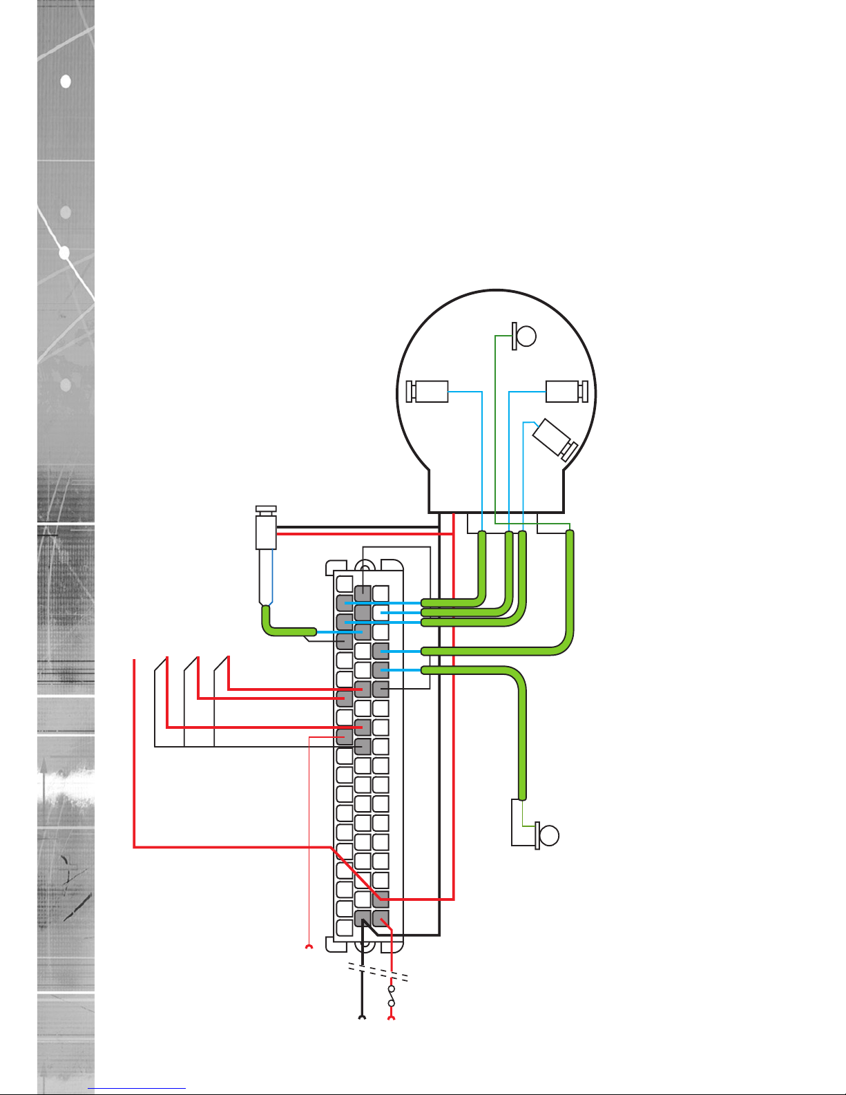
Example wiring - American Schoolbus
This is a typical schoolbus implementation using four cameras and two microphones. Three cameras and
one microphone are housed in a single dome. The driver camera is in an individual housing. The second
microphone is shown as a single cable type. If the microphone has a powered line amplier, power must be
sourced from the switched power from the Transvu.
Two alarm inputs are wired up, one to give indication that the stop arm is operational and the other to
provide a panic button for the driver.
Vehicle ignition is sensed so the unit will power down shortly after the ignition is switched off.
This will also cut power to the cameras and ancilliary equipment, ensuring the vehicle battery is not
attened.
Speed recognition is via a powered sensor. Recorded images can be viewed on the TransVu playback
station.
1
20
38405055
3037
1019
From vehicle
ignition line
Switched Power
from TransVu
Switched power from TransVu
Microsphere
Three
Camera
Dome
Stairwell
Stairwell Vid out
Forward Vid out
Mic out
Mic gnd
Rear Vid out
Vid gnd
+12V Supply
Supply gnd
Forward
Microphone
Rear
Driver
camera
Vid out
+Vrs SupplySupply Gnd
Sense
Gnd
Gnd
Gnd
Sense
Sense
Vid gnd
Panic alarm button
Stop arm contact
Speedo sensor
From vehicle
power supply
Fuse
+
+
-
Page 21
AD network video ©2011
21
TransVu
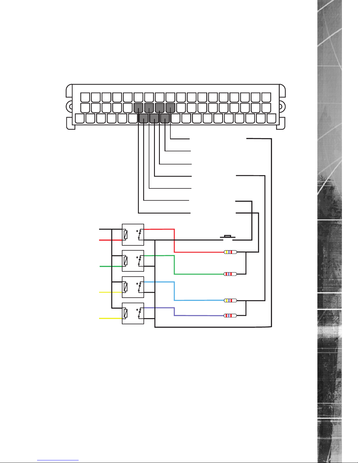
Example wiring - Vehicle Data Logging
The six alarm inputs can be used to monitor the control and signalling status of a vehicle, giving an
accurate and veriable record of the vehicle operation.
The circuit increases the number of vehicle parameters that can be read and recorded by the system
when vehicle logging is enabled in the unit web pages. This conguration allows the readings from the
inputs to be displayed as a ‘dashboard’ within NetVu ObserVer. This information is also recorded in a
seperate, timestamped log which can be downloaded and imported into a spreadsheet for analysis.
To enable data logging, refer to the Conguration Manual.
1
20
38405055
3037
1019
29. Alarm Gnd
11. Alarm 5
30. Alarm 6
12. Alarm 3
31. Alarm 4
13. Alarm 1
32. Alarm 2
Right ind
Right ind
Left ind
Left ind
Accelerator
Accelerator
Panic button
Brakes
Brakes
4k7
4k7
2k7
2k7
Gnd
12/24 V
inputs
Note: Relays are normally closed when no voltage is applied. Relays should be diode protected. If an
input is not required, such as accelerator, the relay may be omitted from the circuit but the 2k7
resistor must remain in circuit, wired to Gnd.
Page 22

AD network video ©2011
22
TransVu
Appendix A - Recommended Tools and Spares
Recommended Tools
Crimps and associated tools for the TransVu 55 way connector.
For the correct installation of the 55 way connector it is essential to use the correct tool and die set.
Tools:
Ergo crimp frame Tyco/Amp part no 539635-1
Die Set Tyco/Amp part no 539674-2
Extractor Tyco/Amp part no 726503-1
Consumables:
Crimps Tyco/Amp part no 927779-1
Connectors:
55 way plug Tyco/Amp part no 963534-1
Further information on crimps and the appropriate tooling are available on the website:
Website: www.tyco.com/amp
Recommended Spares
AD network video recommend the following spares list be maintained.
DM/MP01/TRV Anti vibration mounting plate
DM/SHK01/TRV Anti vibration rubber shocks (feet, nuts, screws & washers x 4)
DM/CN01/TRV Automotive multiway connector
Page 23
AD network video ©2011
23
TransVu
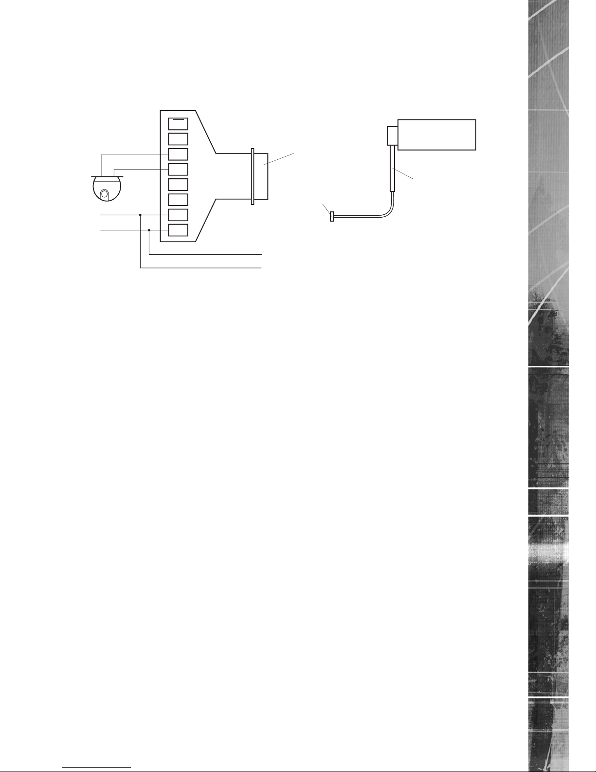
Appendix B - Telemetry
The TransVu unit requires an adapter (Amplicon 485HF9) for telemetry control, which is available from
www.amplicon.co.uk. This converts the RS232 signal to RS485, enabling the TransVu unit to communicate
directly with a single dome camera.
EN
GND
B
A
A’
B’
GND
VDC
9 Way
female
‘D’ type
Amplicon
485HF9
www.amplicon.co.uk
Part No. 90986433
Ground
Dome
5-12 VDC
Power out of TransVu 12V DC
Ground of TransVu
TransVu
Com
1 or 2
9 Way male
‘D’ type
on TransVu
DM TransVu Harness
(DM/HARN/TRV)
Ordering information
Amplicon 485HF9
Part No. 90986433
Website: www.amplicon.co.uk
Page 24

AD network video ©2011
24
TransVu
Appendix C - Technical Specication
Power
Voltage 10 to 30 volts
Power consumption Typically 15 watts
Power Management features Ignition sensing with auto shut down of system and cameras after user preset time.
Auto shut down on nominal low voltage detection after user preset time.
Immediate shut down of system on critical low voltage detection.
Video
Video standard PAL or NTSC (software switchable)
Video inputs 8 (16 available for special order)
Video Signal Composite 1 volt peak to peak
Termination Individual channels at 75 ohms, software switched
Spot Monitor
Spot Monitor Output User selectable sequence / switch on alarm.
Video Recording Standard multiplex method or variable record rate per individual camera.
Maximum record rate 50 images per second PAL, 60 images per second
NTSC.(100pps available on special order)
Record on alarm changes the standard record rate on alarm or individual camera
record rates. Pre and post alarm recording with image archiving.
Video Storage 40, 80, 160 amd 240 Gb permanent hard disk storage.
40, 80 and 120 Gb removable hard disk storage.
Recorded images can be viewed on the TransVu playback station.
VMD – (Video Motion Detection) VMD provided on all camera inputs. 16 zones per camera. Zone trigger adjustable
by percentage pixel count and percentage pixel change.
VMD modes supported: Normal / Last Trigger / Static (museum mode).
Digital Signature The use of digital signatures make it possible to detect if images have been
tampered with.
Audio
Audio Inputs 2 individually selectable Mic or Line.
Mic input level 5 to 500 mV
Line input level 50 to 4000 mV
Frequency response 150 Hz – 3500 Hz
Mic / Line select Software selectable
Phantom power (Mic) Low voltage <5V selectable on internal jumper
Telemetry control RS 232
Supports BBV matrix, VCL matrix, AD network video and American Dynamics
matrix
RS 485 and RS 422 via level convertor
Supports Dennard, Philips, Panasonic, Ademco/VCL and BBV
Alarms 6 x alarm inputs
4 x A/D type
1 x tachometer, or frequency counting input
1 x ignition sense, for power management
Gravitational Sensor (option at point of order)
Gravitational measurements to 2g in x and y axis.
On Board Indicators Four green LED on-board indicators show; network attached, network trafc,
recording active and camera fail.
External Indicators Provision is made to drive two external LED indicators; power on / camera fail and
recording active.
Serial Ports 4 x RS232 serial ports
2 x Full handshake signals
2 x Tx / Rx
Ethernet
Ethernet connection 10/100baseT full & half duplex, auto sensing or software selected.
Bandwidth Default LAN or can be optimised for WAN operation.
Auto download Auto archiving of events on detection of network FTP server.
GPS Supports NMEA standard signaling format.
SMS Supports optional SMS module which reports on system start, alarms, camera fail,
VMD activation, GPS positional messages.
Page 25

AD network video ©2011
25
TransVu
Accepts and replies to remote SMS queries, giving status and position.
GSM / GPRS / CDPD Supports image transmission over mobile telephone / internet access networks.
Dimensions / weight
Case overall 256mm x 248mm x 90mm (excludes plug & flange mount)
10.08in x 9.76in x 3.54in
Base plate area 296mm x 260mm
11.65 in x 10.24 in
Required mounting space 350mm x 380mm x 140mm (excluding cable access)
13.78in x 14.96in x 5.51in
Weight 4.75 Kilograms / 10lbs 8oz
Note: TransVu unit must be mounted horizontally.
Construction Steel metal casing with sealed lid. Integral flange mounting brackets. Aerospace
grade suspension bushes attach the main unit to the base plate mount.
Connection Single 55 pole automotive-specic connector carries all power, data and video.
Temperature Range 0 to 55 degrees Centigrade (32 to 131 deg Fahrenheit)
Port pin outs
COM1 Port
Pin Cable Multipole connector Signal
1 Brown 24 DCD
2 Red 22 RXD
3 Orange 9 TXD
4 Yellow 6 DTR
5 Black 23 GND
6 Not used - 7 Purple 8 RTS
8 Grey 7 CTS
9 Not used - -
COM2 Port
Pin Cable Multipole connector Signal
1 Brown 48 DCD
2 Red 43 RXD
3 Orange 49 TXD
4 Yellow 46 DTR
5 Black 42 GND
6 Blue 47 DSR
7 Purple 44 RTS
8 Grey 45 CTS
9 Not used - -
COM5 Port
Pin Cable Multipole connector Signal
1 Not used - 2 Red 25 RXD
3 Orange 26 TXD
4 Not used - 5 Black 23 GND
6 Not used - 7 Not used - 8 Not used - 9 Not used - -
COM6 Port
Pin Cable Multipole connector Signal
1 Not used - 2 Red 27 RXD
3 Orange 28 TXD
4 Not used - 5 Black 10 GND
6 Not used - 7 Not used - 8 Not used - 9 Not used - -
Page 26

AD network video ©2011
26
TransVu
Page 27

AD network video ©2011
27
TransVu
Index
Alarm Inputs ......................................................................................................................... 15
Amplicon 485HF9 ................................................................................................................. 23
Appendix A - Recommended Tools and Spares ................................................................... 22
Appendix B - Telemetry ........................................................................................................ 23
Appendix C - Technical Specication ................................................................................... 24
Baseplate dimensions & measurements: ............................................................................... 6
Cable Connections ............................................................................................................... 10
Care in feeding cables ............................................................................................................ 5
COM1 Port ........................................................................................................................... 25
COM2 Port ........................................................................................................................... 25
COM5 Port ........................................................................................................................... 25
COM6 Port ........................................................................................................................... 25
Connecting a GPS ................................................................................................................ 14
Connecting a Spot Monitor ................................................................................................... 12
Connecting Audio ................................................................................................................. 13
Connecting Cameras ............................................................................................................ 12
Connecting COM 5 and COM 1 serial ports ......................................................................... 17
Connecting Indicator LEDs ................................................................................................... 16
Connecting the COM 2 serial port ........................................................................................ 18
Connecting to a Network Hub .............................................................................................. 14
Connecting to a PC Network port ......................................................................................... 15
Connecting vehicle power .................................................................................................... 13
Example Installations ........................................................................................................... 19
Example wiring - American Schoolbus ................................................................................. 20
Example wiring - Taxi............................................................................................................ 19
Fitting shock absorbers to the unit. ........................................................................................ 8
Fitting the TransVu to the baseplate ....................................................................................... 9
Installation .............................................................................................................................. 4
Installation space required for the TransVu ............................................................................ 4
Introduction ............................................................................................................................. 3
Mounting restriction for correct G-force implementation ........................................................ 6
Mounting the Baseplate .......................................................................................................... 6
Multipole Connector ............................................................................................................. 10
Multipole Connector Layout ...................................................................................................11
Multipole General Diagram ....................................................................................................11
Notes on installation space .................................................................................................... 5
Ordering information ............................................................................................................. 23
Physical Installation ................................................................................................................ 4
Port pin outs ......................................................................................................................... 25
Product Orientation ................................................................................................................ 4
Recommended Spares ......................................................................................................... 22
Recommended Tools ........................................................................................................... 22
System Documentation .......................................................................................................... 3
TransVu end view dimensions: ............................................................................................... 8
TransVu top view dimensions ................................................................................................. 7
Page 28

AD network video Europe
Neckarstrafle 15,
41836 Hückelhoven, Germany
AD network video France
9-13 rue du Moulinet
75013 Paris, France
AD network video Slovenia
Delavska cesta 26,
4208 Sencure, Slovenia
AD network video Benelux
Joseph Chantraineplantsoen 1,
3070 Kortenberg, Belgium
AD network video USA.
14434 Albemarle Point Place, Suite 100,
Chantilly, Virginia 20151 USA
AD network video USA.
23456 Hawthorne Blvd.
Suite 100, Torrance,
CA 90505, USA
AD network video, Australia PTY.
5/3 Packard Avenue, Castle Hill,
NSW 2154, Australia
AD network video, Asia PTY
16 New Industrial Road,
#03-03 Hudson Techno Centre,
Singapore 536204
AD network video Middle East
Building 12, Suite 302, P.O. Box 500291, Dubai Internet
City, Dubai, United Arab Emirates
AD network video (Malta) Ltd.
BLB017, Bulebel Industrial Estate,
Zejtun, ZTN08, Malta
AD network video Ltd.
1200 Daresbury Park, Daresbury,
Cheshire, WA4 4HS, UK
Installed by
MI-I-TVI/E1-0
 Loading...