

Page 1

MANUAL
USER
1U LCD Keyboard Drawer
20” Screen Size
Models
NVP120 Series
-With KVM Options
Models
SNK120 Series
-With KVM Options
-Designed for SUN Solaris
Page 2

NVP120 / SNK120 User Manual
Table of Contents
Chapter 1 Getting Started
1.1 Important Safeguards 1
1.2 Regulatory Notice 2
1.3 Package Contents 3
1.4 Before Installation 4
1.5 Unpacking 4
1.6 Optional Accessories 4
1.7 Peripheral Products 5
1.8 Structure Diagram 5
1.9 Installation 6-7
1.10 How to Use NVP / SNK Series LCD Keyboard Drawer 8
1.11 SNK120 (Single console)
- Use NB-6 to connect to server via USB interface 9
1.12 SNK120 (Single console)
- Use NB-6 to connect to KVM via USB interface 9
1.13 NVP120 (Single console)
- Use NE-6 to connect to server via PS/2 interface 10
1.14 NVP120 (Single console)
- Use NE-6 to connect to KVM via PS/2 interface 10
1.15 NVP120 (Single console)
- Use NE-6 to connect to server via USB interface 11
1.16 NVP120 (Single console)
- Use NE-6 to connect to KVM via USB interface 11
Chapter 2 Operation
2.1 On-screen Display Operation 12
2.2 On-screen Menu 13
Chapter 3 Standard Specification
3.1 Specifications 14
3.2 Keyboard & Mouse 15
3.3 How to Use “NS” Keyboard 16
ii-Tech Company LLC TOLL FREE: (888) 483-2418 • EMAIL: [email protected] • WEB: www.iTechKVM.com
Page 3

NVP120 / SNK120 User Manual
Table of Contents
Chapter 4 Optional Specification
4.1 KVM Options 17
4.2 DVI-D Input Option 17
4.3 BNC + S-Video Option 17
4.4 Audio Option 18
4.5 DC power Options 19
Chapter 5 Troubleshooting
Chapter 6 Dimensions
21
20
ii-Tech Company LLC TOLL FREE: (888) 483-2418 • EMAIL: [email protected] • WEB: www.iTechKVM.com
Page 4

NVP120 / SNK120 User Manual
1.1 Important Safeguards
Please read all of these instructions carefully before you use the device. Save this manual for future reference.
What the warranty does not cover
■ Any product, on which the serial number has been defaced, modifi ed or removed.
■ Damage, deterioration or malfunction resulting from:
■ Removal, installation, and set-up service charges.
□ Accident, misuse, neglect, fi re, water, lightning, or other acts of nature, unauthorized product modifi cation, or failure to follow instructions supplied with the product.
□ Repair or attempted repair by anyone not authorized by us.
□ Any damage of the product due to shipment.
□ Removal or installation of the product.
□ Causes external to the product, such as electric power fluctuation or failure.
□ Use of supplies or parts not meeting our specifications.
□ Normal wear and tear.
□ Any other causes which does not relate to a product defect.
Chapter 1
ii-Tech Company LLC TOLL FREE: (888) 483-2418 • EMAIL: [email protected] • WEB: www.iTechKVM.com
Page 5

NVP120 / SNK120 User Manual
1.2 Regulatory Notice
Legal Information
First English printing, October 2002
Information in this document has been carefully checked for accuracy; however, no guarantee is given to the
correctness of the contents. The information in this document is subject to change without notice. We are not
liable for any injury or loss that results from the use of this equipment.
Safety Instructions
■ Unplug equipment before cleaning. Don’t use liquid or spray detergent; use a moist cloth.
■ Keep equipment away from excessive humidity and heat. Preferably, keep it in an air-conditioned
environment with temperatures not exceeding 40º Celsius (104º Fahrenheit).
■ When installing, place the equipment on a sturdy, level surface to prevent it from accidentally falling and
causing damage to other equipment or injury to persons nearby.
■ When the drawer is in an open position, do not cover, block or in any way obstruct the gap between it and
the power supply. Proper air convection is necessary to keep it from overheating.
■ Arrange the equipment’s power cord in such a way that others won’t trip or fall over it.
■ If you are using a power cord that didn’t ship with the equipment, ensure that it is rated for the voltage
and current labeled on the equipment’s electrical ratings label. The voltage rating on the cord should be
higher than the one listed on the equipment’s ratings label.
■ Observe all precautions and warnings attached to the equipment.
■ If you don’t intend on using the equipment for a long time, disconnect it from the power outlet to prevent
being damaged by transient over-voltage.
■ Keep all liquids away from the equipment to minimize the risk of accidental spillage. Liquid spilled on to
the power supply or on other hardware may cause damage, fi re or electrical shock.
■ Only qualifi ed service personnel should open the chassis. Opening it yourself could damage the equipment
and invalidate its warranty.
■ If any part of the equipment becomes damaged or stops functioning, have it checked by qualifi ed service
personnel.
Regulatory Notices Federal Communications Commission (FCC)
This equipment has been tested and found to comply with the limits for a Class B digital device, pursuant to
Part 15 of the FCC rules. These limits are designed to provide reasonable protection against harmful interference
in a residential installation.
Any changes or modifi cations made to this equipment may void the user’s authority to operate this equipment.
This equipment generates, uses, and can radiate radio frequency energy and, if not installed and used
in accordance with the instructions, may cause harmful interference to radio communications.
However, there is no guarantee that interference will not occur in a particular installation. If this equipment
does cause harmful interference to radio or television reception, which can be determined by turning the
equipment off and on, the user is encouraged to try to correct the interference by one or more of the following
measures:
■ Re-position or relocate the receiving antenna.
■ Increase the separation between the equipment and receiver.
■ Connect the equipment into an outlet on a circuit different from that to which the receiver is connected.
Chapter 1
ii-Tech Company LLC TOLL FREE: (888) 483-2418 • EMAIL: [email protected] • WEB: www.iTechKVM.com
Page 6
NVP120 / SNK120 User Manual
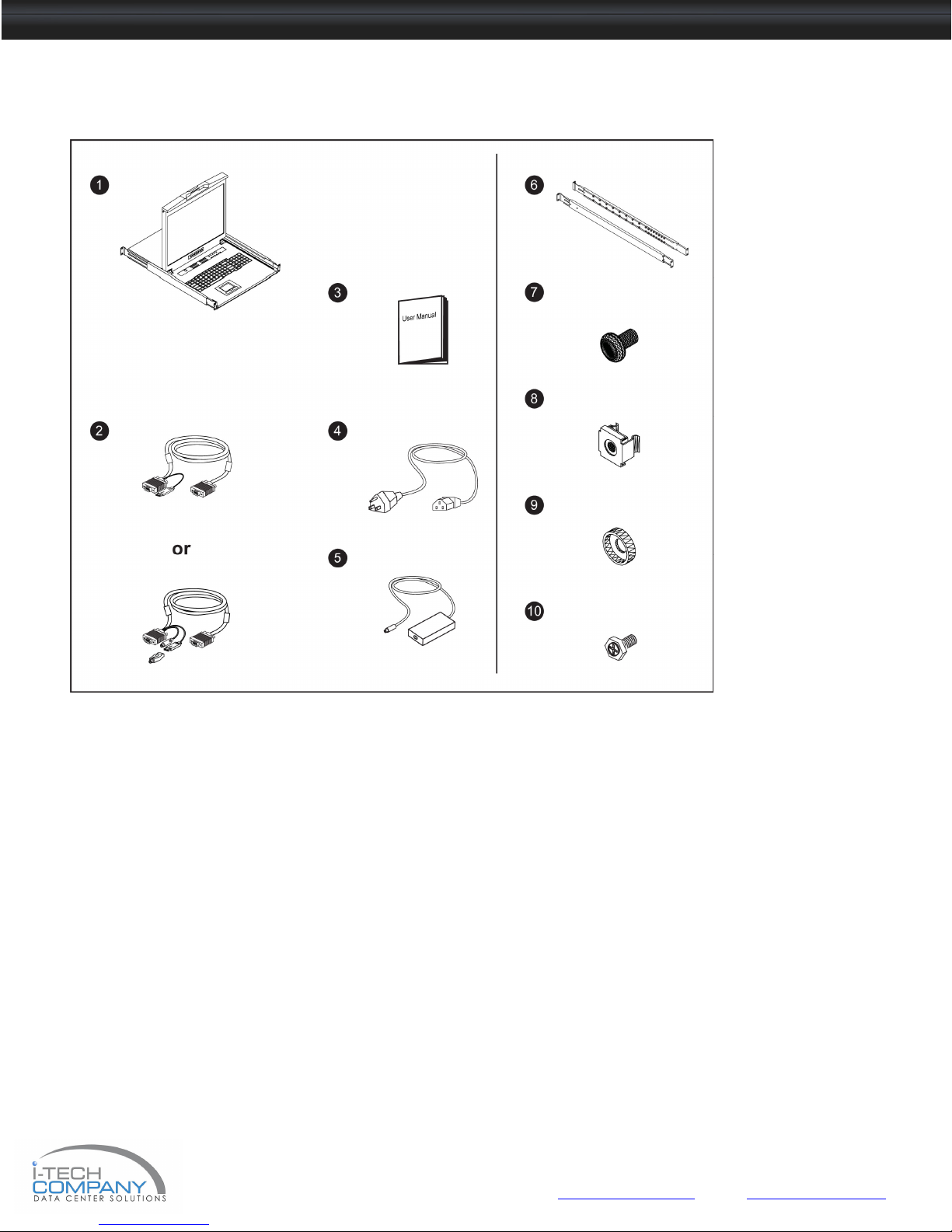
1.3 Package Contents
1 LCD keyboard drawer x 1 pc
2 . NB-6 USB 2-in-1 KVM cable x 1 pc (for SNK Series) or
NE-6 Combo 4-in-1 KVM cable x 1 pc (for L series)
3. User manual x 1 pc
4. Power cord x 1 pc
5. Auto switch power adapter ( for external power version) x 1 pc
6. Mounting bracket x 2 pcs
7. M6*15mm screw x 8 pcs
8. M6 cage nut x 8 pcs
9. Cup washer x 8 pcs
10.M3.2*6mm screw x 4 pcs
Chapter 1
ii-Tech Company LLC TOLL FREE: (888) 483-2418 • EMAIL: [email protected] • WEB: www.iTechKVM.com
Page 7
NVP120 / SNK120 User Manual
1.4 Before Installation
Chapter 1
■ It is very important to locate the LCD Keyboard Drawer in a suitable environment.
■ The surface for placing and fi xing the LCD Keyboard Drawer should be stable and level or mounted into a suitable
cabinet.
■ Make sure the place has good ventilation, is out of direct sunlight, away from sources of excessive dust, dirt, heat,
water, moisture and vibration.
■ Position LCD Keyboard Drawer with respect to related facilities.
1.5 Unpacking
The LCD keyboard drawer comes with the standard parts shown on the package contents. Check and make sure they are
included and in good condition. If anything is missing, or damage, contact the supplier immediately.
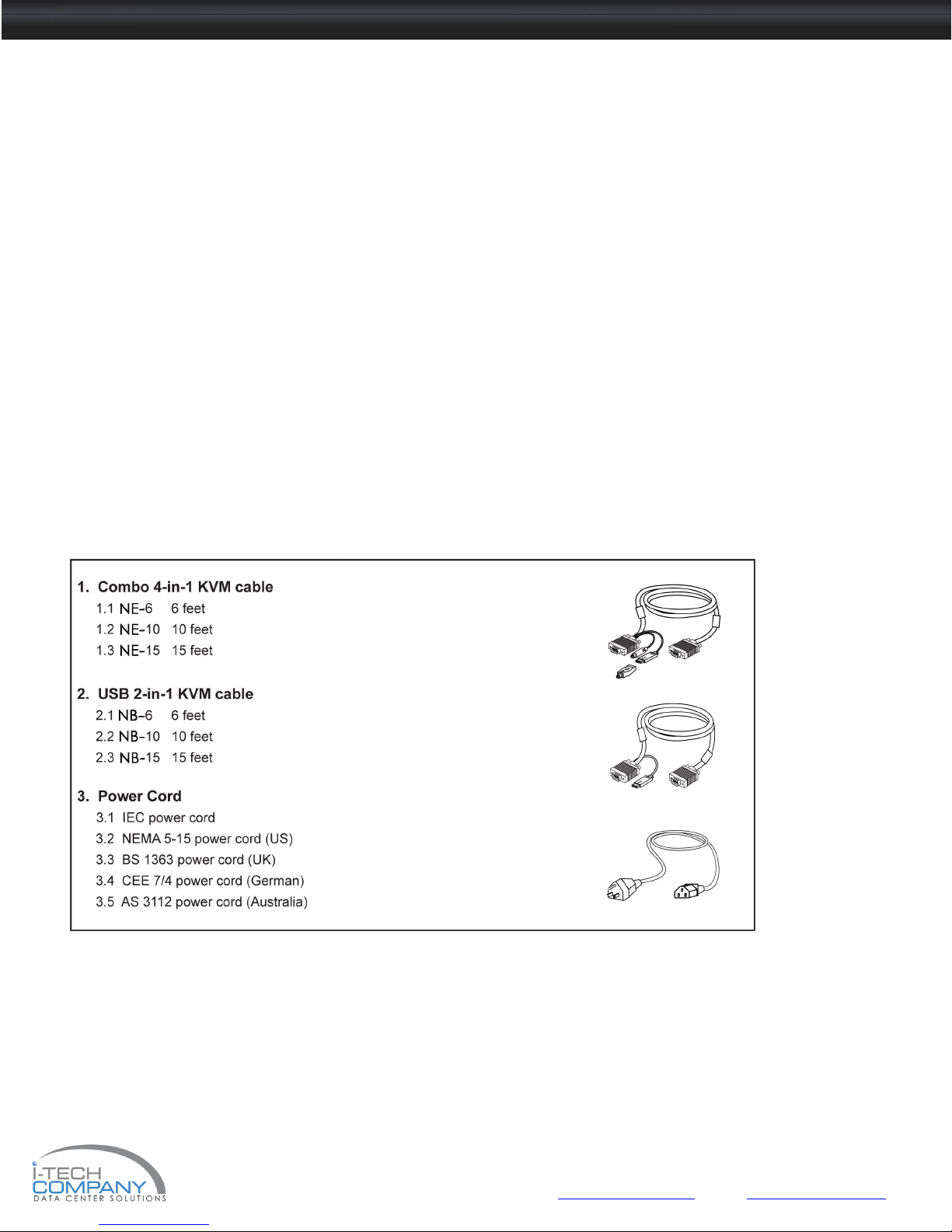
1.6 Optional Accessories
Remarks :
■ NB-6 is for SNK Series only.
ii-Tech Company LLC TOLL FREE: (888) 483-2418 • EMAIL: [email protected] • WEB: www.iTechKVM.com
Page 8
NVP120 / SNK120 User Manual
1.7 Peripheral Products
Item Model No. Description
Matrix Cat6 KVM
MC0116 / MC0216 / MC0316
MC1116 / MC1216 / MC2116
MC0132 / MC0232 / MC0332
MC1132 / MC1232 / MC2132
Matrix Cat6 16 port KVM
Matrix IP Cat6 16 port KVM
Matrix Cat6 32 port KVM
Matrix IP Cat6 32 port KVM
Matrix DB-15 KVM
M018/ M028 / M038
M118 / M128 / M218
M0116 / M0216 / M0316
M1116 / M1216/ M2116
Matrix DB-15 8 port KVM
Matrix IP DB-15 8 port KVM
Matrix DB-15 16 port KVM
Matrix IP DB-15 16 port KVM
Combo Cat6 KVM
NVC800 / NVCCE800 / NVCIP800
NVC1600 / NVCCE1600 / NVCIP1600
NVC3200/ NVCCE3200 / NVCIP3200
Combo Cat6 8 port KVM
Combo Cat6 16 port KVM
Combo Cat6 32 port KVM
Combo DB-15 KVM
PS/2 DB-15 KVM
Remarks :
■ “SNK” Series is for Matrix & Combo KVM only.
NVS801 / NVCE800 / NVIP-802
NVS1601 / NVCE1600 / NVIP-1602
NV401A / NV801A / NV1601A 4 / 8 / 16 port PS/2 DB-15 KVM
Combo DB-15 8 port KVM
Combo DB-15 16 port KVM
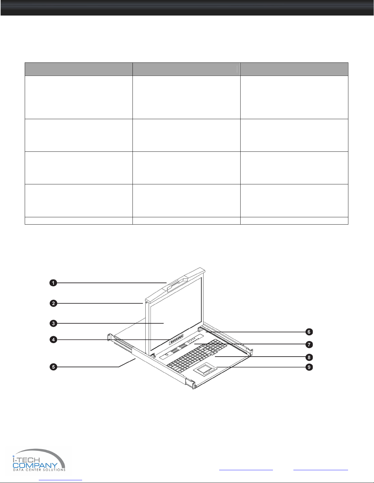
1.8 Structure Diagram
1. Carry handle to release the 2-pt lock
2. 2-point lock
3. LCD interchangeable module kit
4. LCD membrane
5. “One Man” Installation Slide
6. Micro switch for screen auto power off
7. Membrane switch (KVM option)
8. Keyboard interchangeable module kit
9. 2 buttons mouse interchangeable module kit
Chapter 1
ii-Tech Company LLC TOLL FREE: (888) 483-2418 • EMAIL: [email protected] • WEB: www.iTechKVM.com
Page 9

NVP120 / SNK120 User Manual
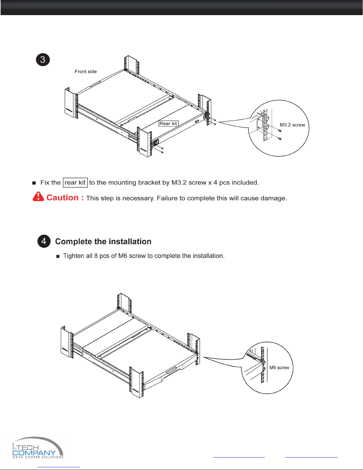
1.9 Installation
■ Pick up the LCD tray.
■ Insert the LCD tray by inner slide members into the mounting bracket.
Chapter 1
ii-Tech Company LLC TOLL FREE: (888) 483-2418 • EMAIL: [email protected] • WEB: www.iTechKVM.com
Page 10
NVP120 / SNK120 User Manual
1.9 Installation Chapter 1
ii-Tech Company LLC TOLL FREE: (888) 483-2418 • EMAIL: [email protected] • WEB: www.iTechKVM.com
Page 11
NVP120 / SNK120 User Manual
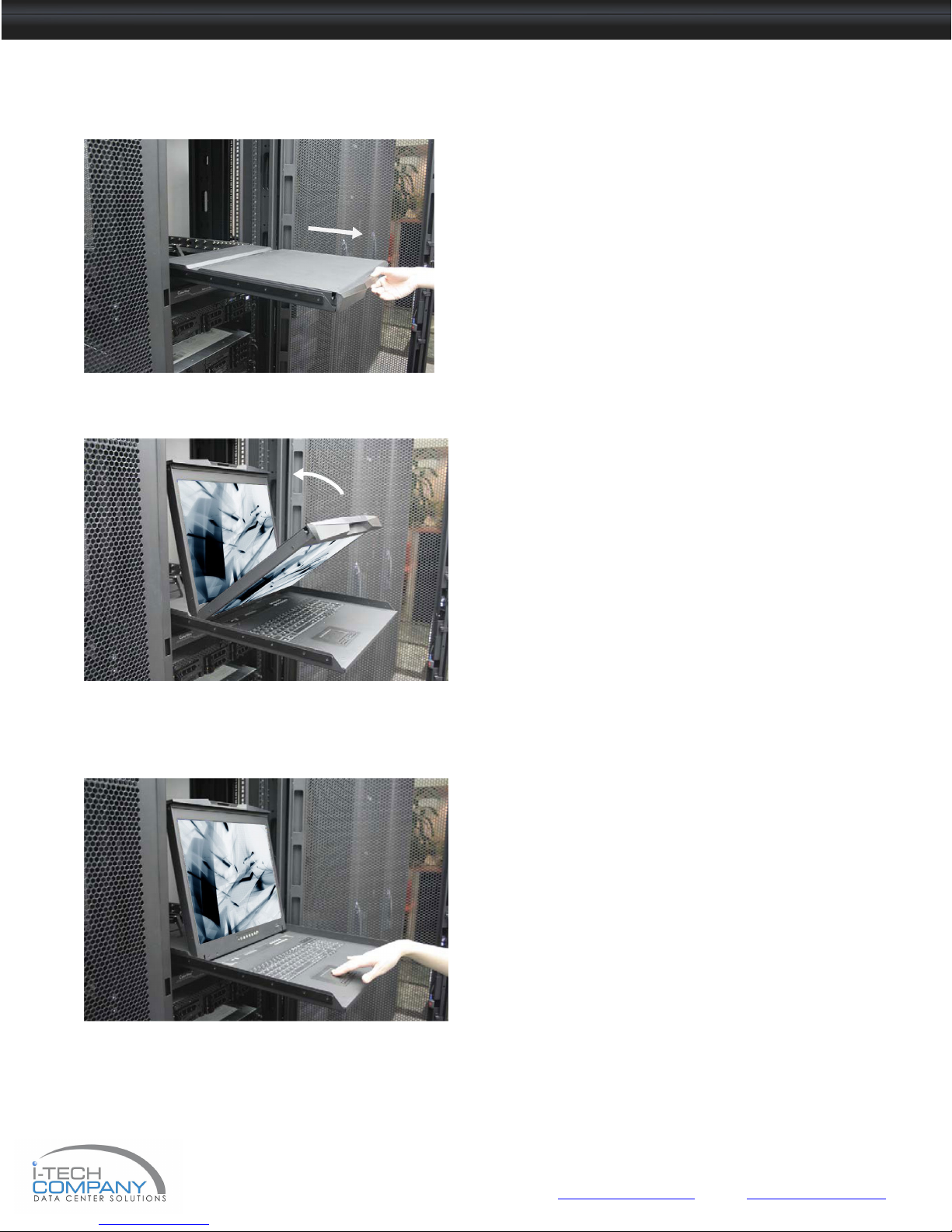
1.10 How to Use NVP / SNK Series LCD Keyboard Drawer
Figure 1. Sliding out the LCD keyboard drawer by pressing
the carry
Figure 2. Flipping up the LCD to a suitable angle.
Figure 3. Operating the LCD keyboard drawer
■ Press the carry handle button. Gently pull the
carry handle toward the front of the LCD shown
in Figure 1.
■ Flip up the LCD to a suitable angle shown in
Figure 2.
■ Operate the LCD keyboard drawer shown in
Figure 3.
Chapter 1
ii-Tech Company LLC TOLL FREE: (888) 483-2418 • EMAIL: [email protected] • WEB: www.iTechKVM.com
Page 12
NVP120 / SNK120 User Manual
■ For the LCD keyboard drawer with KVM switch built
-
in, please refer to attached KVM switch user manual.
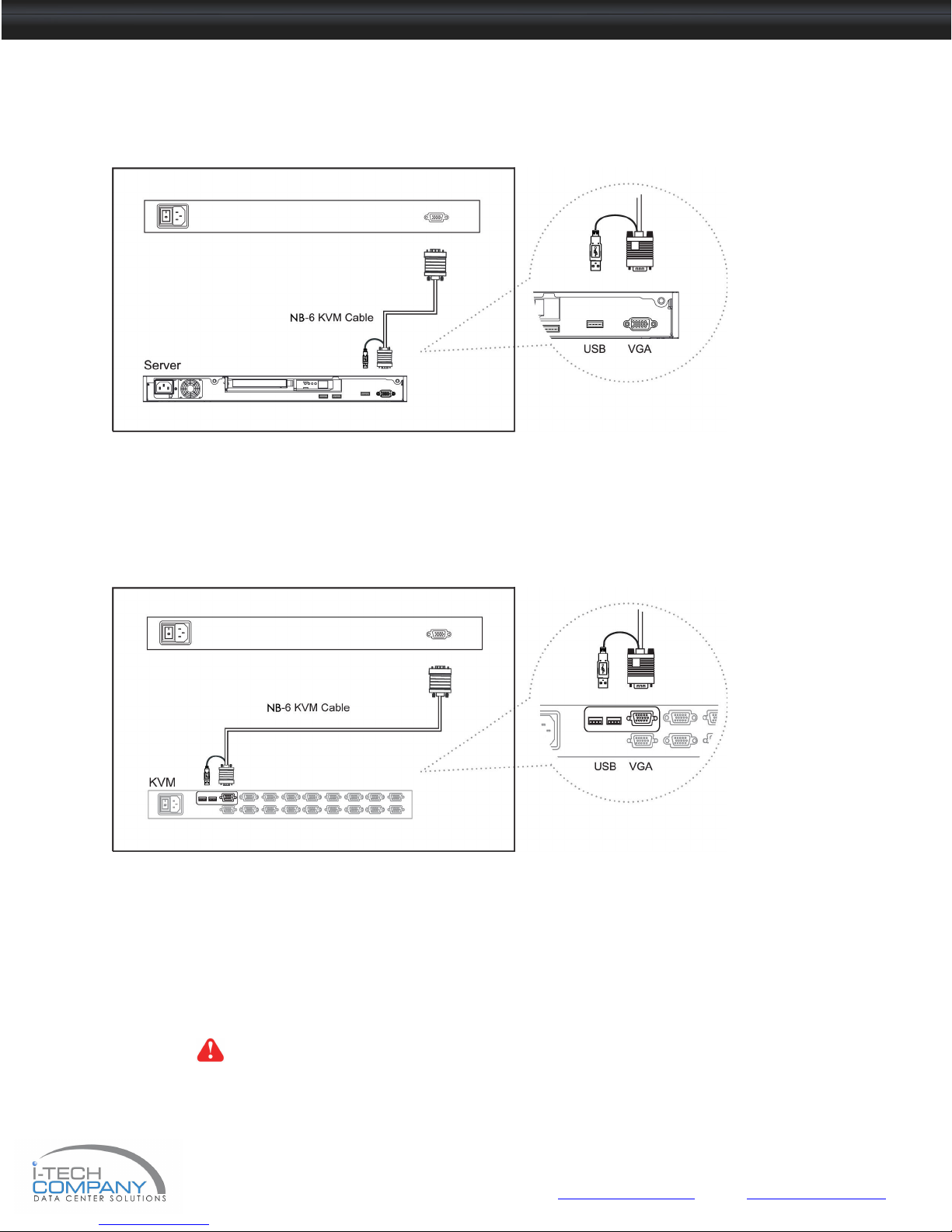
1.11 SNK120 (Single console)
- Use NB-6 to connect to server via USB interface
Figure 4. Example of connecting NB-6 2-in-1 USB KVM cable to server via USB
interface
1.12 SNK120 (Single console)
- Use NB-6 to connect to KVM via USB interface
Figure 5. Example of connecting NB-6 2-in-1 USB KVM cable to KVM via USB
interface
Remarks :
■ The above connection is only for the LCD keyboard without KVM switch built-in.
Caution : The LCD keyboard drawer is hot-pluggable, but components of connected devices,
such as the servers and KVM switch, may not be hot-pluggable. Plugging and unplugging
cables while servers and KVM are powered on may cause irreversible damage to
the servers, KVM and LCD keyboard drawer. Before attempting to connect anything to the
LCD keyboard drawer, we suggest turning off the power to all devices before connecting
them. Apply power to connected devices again only after the LCD keyboard is receiving
power. The company is not responsible for damage caused in this way.
Chapter 1
ii-Tech Company LLC TOLL FREE: (888) 483-2418 • EMAIL: [email protected] • WEB: www.iTechKVM.com
Page 13

NVP120 / SNK120 User Manual
■ For the LCD keyboard drawer with KVM s
witch built
-
in, please refer to attached KVM switch user manual.
1.13 NVP120 (Single console)
- Use NE-6 to connect to server via PS/2 interface
Figure 6. Example of connecting NE-6 Combo 4-in-1 KVM cable to server via
PS/2 interface
1.14 NVP120 (Single console)
- Use NE-6 to connect to KVM via PS/2 interface
Figure 7. Example of connecting NE-6 Combo 4-in-1 KVM cable to KVM via PS/2
interface
Remarks :
■ The above connection is only for the LCD keyboard without KVM switch built-in.
Caution : The LCD keyboard drawer is hot-pluggable, but components of connected devices,
such as the servers and KVM switch, may not be hot-pluggable. Plugging and unplugging
cables while servers and KVM are powered on may cause irreversible damage to
the servers, KVM and LCD keyboard drawer. Before attempting to connect anything to the
LCD keyboard drawer, we suggest turning off the power to all devices before connecting
them. Apply power to connected devices again only after the LCD keyboard is receiving
power. The company is not responsible for damage caused in this way.
Chapter 1
ii-Tech Company LLC TOLL FREE: (888) 483-2418 • EMAIL: [email protected] • WEB: www.iTechKVM.com
Page 14
NVP120 / SNK120 User Manual
■ For the LCD keyboard drawer with KVM switch built
-
in, please refer to attached KVM switch user manual.
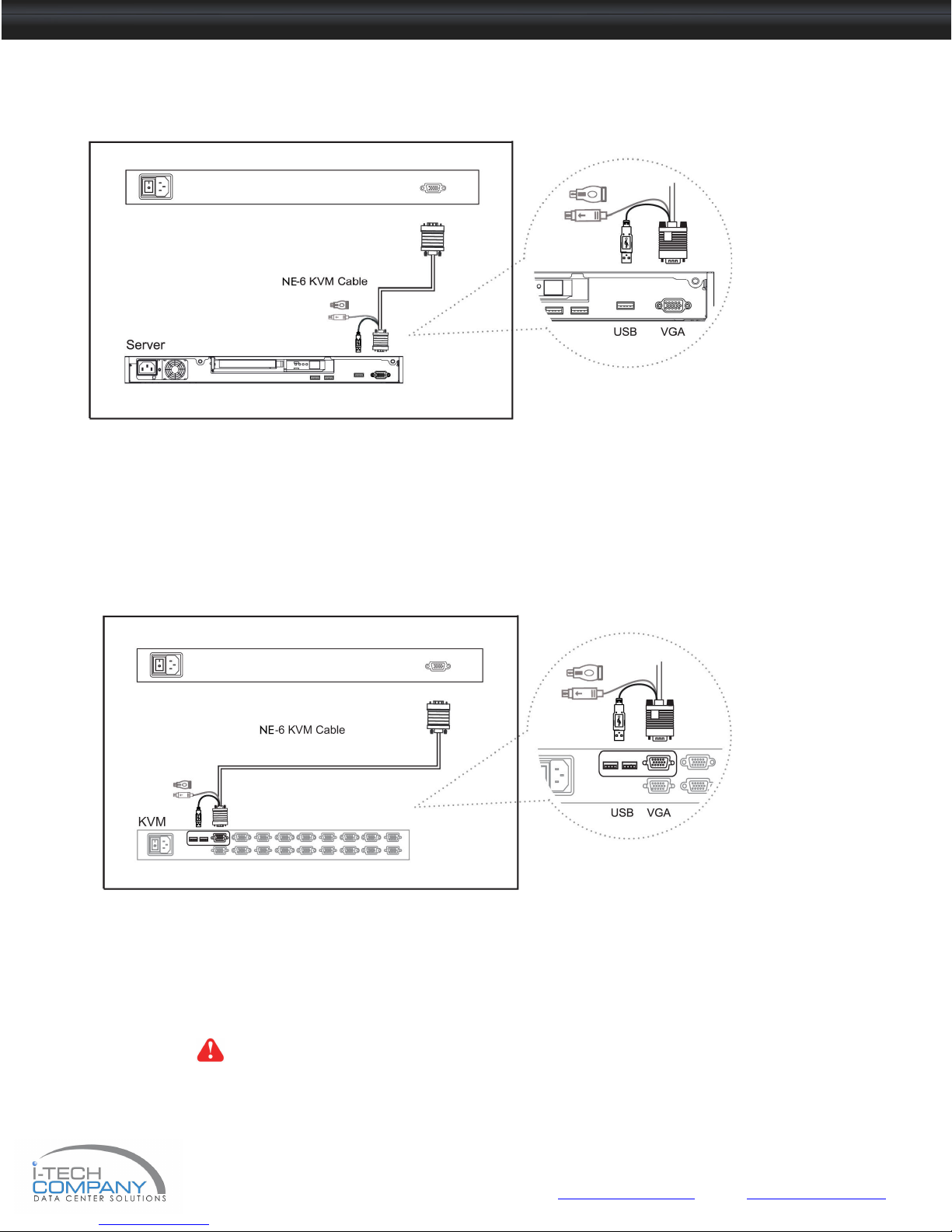
1.15 NVP120 (Single console)
- Use NE-6 to connect to server via USB interface
Figure 8. Example of connecting NE-6 Combo 4-in-1 KVM cable to server via USB
interface
1.16 NVP120 (Single console)
- Use NE-6 to connect to KVM via USB interface
Figure 9. Example of connecting NE-6 Combo 4-in-1 KVM cable to KVM via USB
interface
Remarks :
■ The above connection is only for the LCD keyboard without KVM switch built-in.
Caution : The LCD keyboard drawer is hot-pluggable, but components of connected devices,
such as the servers and KVM switch, may not be hot-pluggable. Plugging and unplugging
cables while servers and KVM are powered on may cause irreversible damage to
the servers, KVM and LCD keyboard drawer. Before attempting to connect anything to the
LCD keyboard drawer, we suggest turning off the power to all devices before connecting
them. Apply power to connected devices again only after the LCD keyboard is receiving
power. The company is not responsible for damage caused in this way.
Chapter 1
ii-Tech Company LLC TOLL FREE: (888) 483-2418 • EMAIL: [email protected] • WEB: www.iTechKVM.com
Page 15

NVP120 / SNK120 User Manual
2.1 On-screen Display Operation
Membrane Switch Function
Power light
Green = On
Orange = Power saving
Power on / off LCD
Display the OSD menu
Scrolls through menu options and adjusts the displayed control
Exit the OSD screen
Chapter 2
ii-Tech Company LLC TOLL FREE: (888) 483-2418 • EMAIL: [email protected] • WEB: www.iTechKVM.com
Page 16
NVP120 / SNK120 User Manual
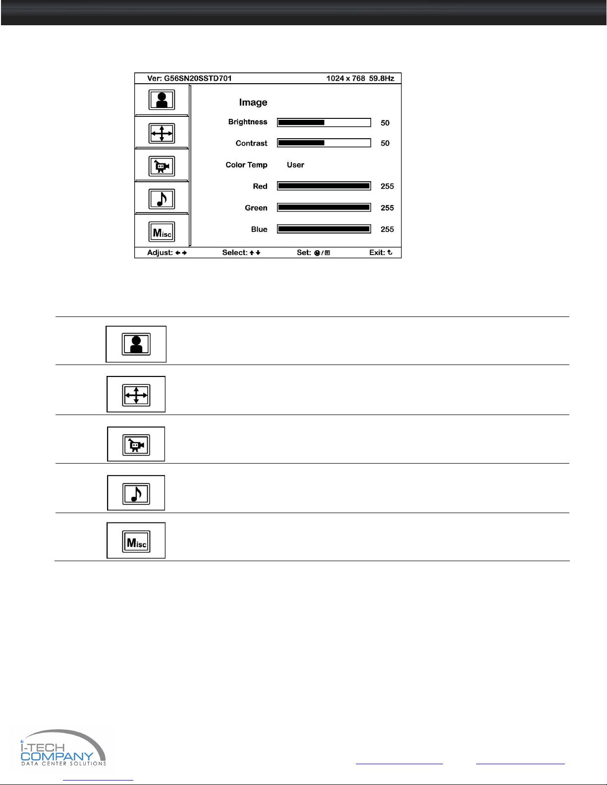
2.2 On-screen Menu
OSD Configuration Page
Image:
To enter into the brighness, contrast, color temp, red, green, and
blue
Geometry:
To enter into the auto adjust, H position, V position, phase and
clock
Video:
To enter into the colour, tint, sharpness, noise reduction, DCDi and
TV Setup
Audio:
To enter into volume, bass, treble, balance, AVL and mute
Misc:
To enter into the language, OSD position, graphic mode, ratio,
reset and timer
Chapter 2
ii-Tech Company LLC TOLL FREE: (888) 483-2418 • EMAIL: [email protected] • WEB: www.iTechKVM.com
Page 17
NVP120 / SNK120 User Manual
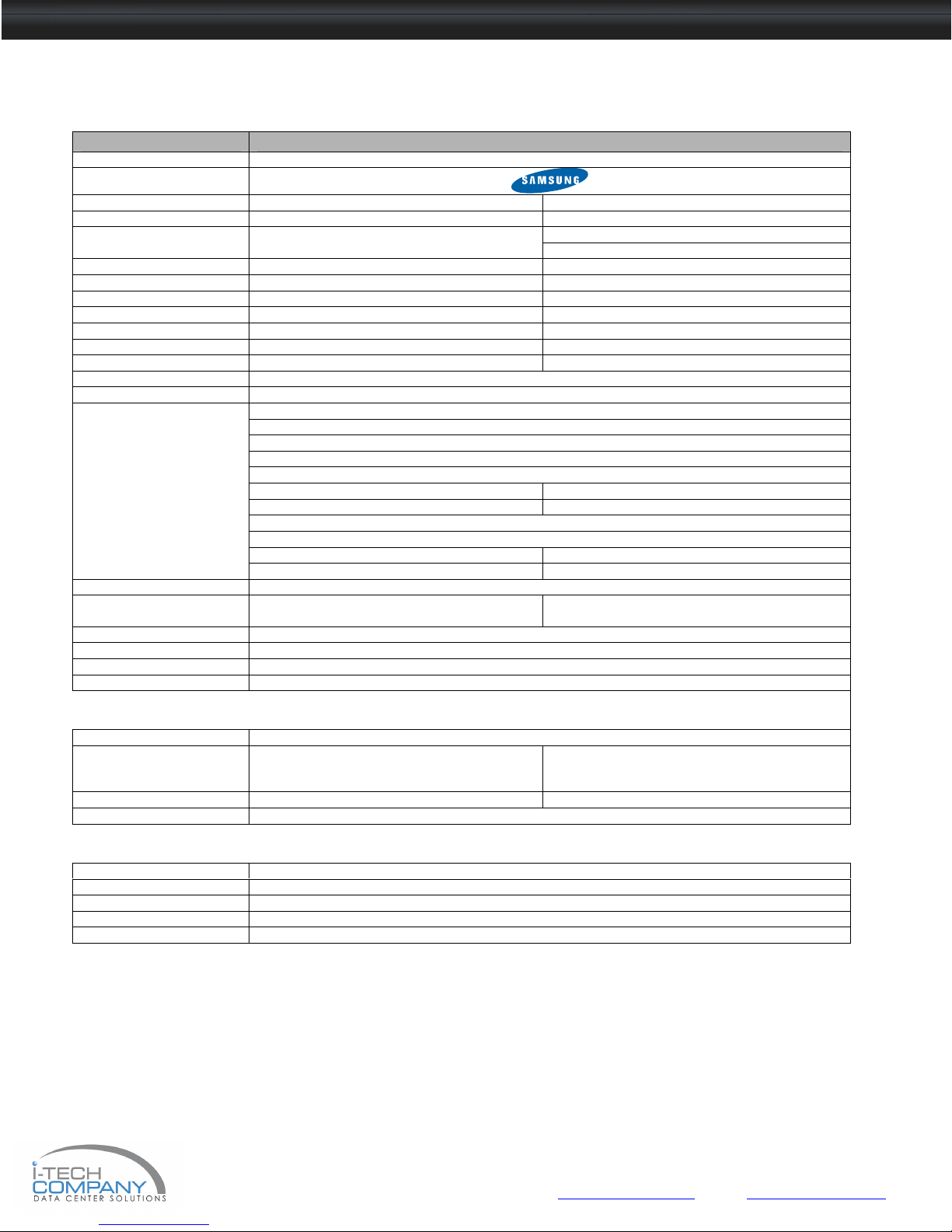
3.1 Specifications
Item Description
Form Factor 1U rack mounting on slide-out rails
LCD Manufacturer
Series NVP SNK
Diagonal Size 20" TFT 20" TFT
Brightness (cd/m²) 300 300
Color Support 16.7 M 16.7 M
Contrast Ratio (typ.) 800:1 800:1
Viewing Angle (H/V) 160° x 160° 160° x 160°
Display Area (mm) 408 x 306 408 x 306
Tr Response Time (ms) 1 1
LCD Panel MTBF (hrs) 50,000 50,000
VGA Signal Input Analog RGB, 0.7Vp-p
Sync. Type Separate H/V, Composite, SOG
Resolution
Plug & Play DDC EDID 1.3
Console Port (Combo) DB-15 connector for VGA / keyboard / mouse
Power Input Auto-sensing 100 to 240VAC, 50 / 60Hz
Power Consumption Max. 48 Watt, Standby 5 Watt
Compatibility Multi-platform - Mix PCs, SUNs, IBMs, HPs & DELLs.
Regulation Approval FCC, CE
Options
KVM Integration Matrix & combo KVM with IP console and 2-console selection
Keyboard & mouse Full size keyboard integrated with touchpad
Graphic Input DVI-D, BNC & S-Video input
DC Power DC power input with 12V, 24V, 48V selection
Environmental
Operation 0° to 50°C Degree
Storage -5° to 60 °C Degree
Relative Humidity 5~90%, non-condensing
Shock 10G acceleration (11ms duration)
Vibration 5~500Hz 1G RMS random vibration
1152 x 900 (Direct) Max. Resolution 1600 x 1200
1600 x 1200 (Native)
1280 x 720, 60/ 75 Hz 1280 x 720, 60 Hz
1280 x 1024, 60/ 70/ 75 Hz 1280 x 1024, 60/ 75 Hz
1152 x 900, 60/ 76 Hz
(Combo interface)
720 x 400, 70 Hz
640 x 480, 60/ 70/ 72/ 75 Hz
800 x 600, 60/ 70/ 72/ 75 Hz
1024 x 768, 60/ 70/ 75 Hz
1152 x 864, 60/ 70/ 75 Hz
1400 x 1050, 60 Hz
1600 x 1200, 60 Hz
DB-15 connector for VGA / keyboard / mouse
Support USB servers or Combo KVM switches
& 2 buttons mouse interchangeable module
kit
SUN-compatible keyboard integrated
with touchpad
& 2 buttons mouse interchangeable module kit
Chapter 3
ii-Tech Company LLC TOLL FREE: (888) 483-2418 • EMAIL: [email protected] • WEB: www.iTechKVM.com
Page 18
NVP120 / SNK120 User Manual
■ USB interface
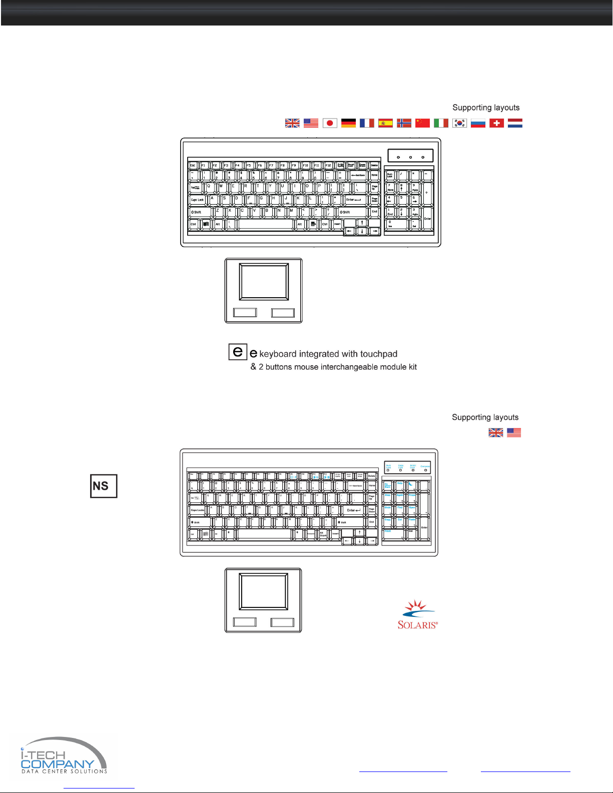
3.2 Keyboard & Mouse
For NVP120 series
For SNK120 series
NS keyboard integrated with touchpad & 2 buttons mouse interchangeable module kit
■ Incorporates SUN keys, including Stop, Cut, Paste, Compose, Copy and Help
■ 104 key notepad keyboard with full numerical pad and SUN function
Chapter 3
ii-Tech Company LLC TOLL FREE: (888) 483-2418 • EMAIL: [email protected] • WEB: www.iTechKVM.com
Page 19
NVP120 / SNK120 User Manual
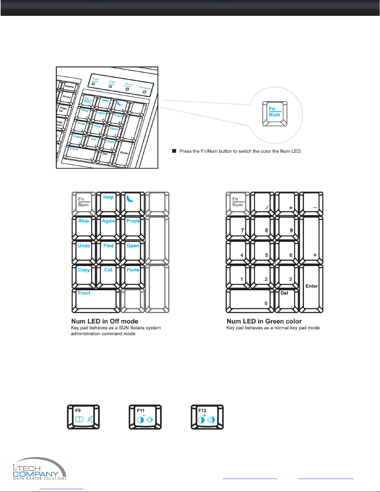
3.3 How to Use "NS" keyboard
■ NS SUN-compatible keyboard incorporates SUN short-cut keys.
Three Audio / Display keys are located in the upper-right corner of the NS keyboard:
■ Audio : Mute, decrease in volume and increase in volume.
■ Display : Degauss, decrease contrast and increase contrast.
■ Please ask your supplier for full details
Chapter 3
ii-Tech Company LLC TOLL FREE: (888) 483-2418 • EMAIL: [email protected] • WEB: www.iTechKVM.com
Page 20

NVP120 / SNK120 User Manual
4.1 KVM Options
Our KVM is designed to seamlessly integrate into the rear of our full range of LCD drawer solutions:
■ For KVM operation, please refer to KVM user manual
■ Option with Multiple consoles Matrix KVM
■ Option with high density & cost effi cient Combo KVM integration with either 8 / 16 / 32 ports
■ Option with low cost PS/2 KVM
■ Please ask your supplier for full KVM details
Remarks
■ SNK Series is for Matrix & Combo KVM only.
4.2 DVI-D Option
Remarks :
■ Package includes 1 x 6ft DVI-D cable
4.3 BNC + S-Video Option
Remarks :
■ Package includes 1 x 6ft S-Video cable
Chapter 4
ii-Tech Company LLC TOLL FREE: (888) 483-2418 • EMAIL: [email protected] • WEB: www.iTechKVM.com
Page 21
NVP120 / SNK120 User Manual
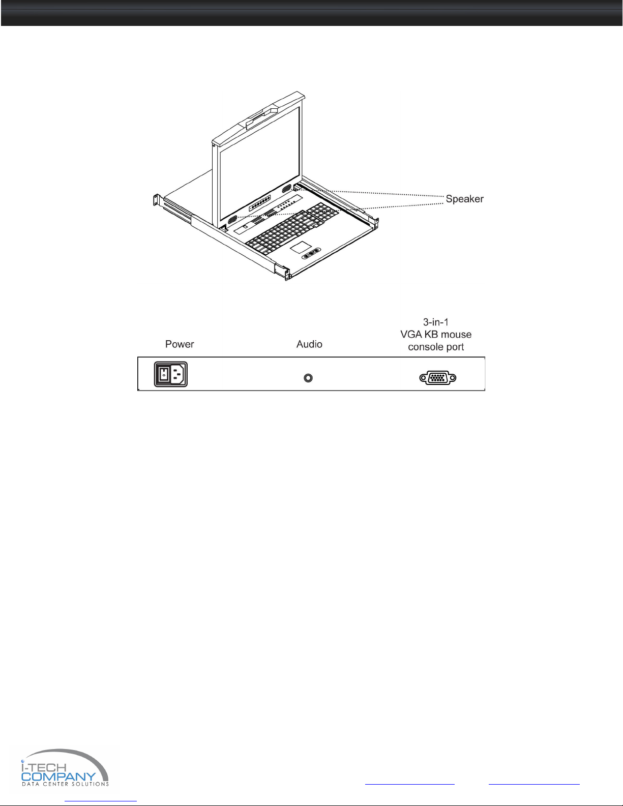
4.4 Audio Option
Remarks
■ Audio input is 35mm audio plug
■ The speaker is sharing the same power with LCD.
Chapter 4
ii-Tech Company LLC TOLL FREE: (888) 483-2418 • EMAIL: [email protected] • WEB: www.iTechKVM.com
Page 22

NVP120 / SNK120 User Manual
4.5 DC Power Options
Model
Input rating
Input voltage: 12-Volt 24-Volt 48-Volt
Input range: 9 ~ 18V 18 ~ 36V 36 ~ 75V
Input current
- No load 50 mA 50mA 50 mA
- Full load 4950 mA 2450 mA 1220 Ma
Output rating
Output voltage: 12-Volt 12-Volt 12-Volt
Output current: 4.16A 4.16A 4.16A
Efficiency
Remarks :
■ Package does not include power cord and AC power adapter
12V
84% 85% 85%
24V
Chapter 4
48V
ii-Tech Company LLC TOLL FREE: (888) 483-2418 • EMAIL: [email protected] • WEB: www.iTechKVM.com
Page 23

NVP120 / SNK120 User Manual
5.1 Troubleshooting
1. Is interference signal appeared on LCD normal when shutting down the computer ?
In rare cases, interference may appear on the monitor. This may be caused by signal rate of VGA card and is
considered
normal. The image quality can be improved by adjusting the phase or pixel rate automatically or manually.
2. The membrane power light is not ON
Press the power On / Off on LCD membrane to check if the monitor is in the ON mode.
Check the power cord is properly connected to the LCD keyboard drawer and power outlet.
3. Screen image is not centered or sized properly
Press
Adjust the H-position and V-position settings via On-screen menu
4. Is the LCD keyboard drawer hot-pluggable ?
The LCD keyboard drawer is hot-pluggable, but components of connected devices, such as the servers and KVMs,
may
not be hot-pluggable. We suggest turning off the power to all devices before connecting them. Apply power to
connected
devices again only after the LCD keyboard receives power.
5. How do I adjust the resolution?
To change monitor resolution, click Start -> Control Panel -> Display. Select Setting tab to adjust the monitor resolution
in Desktop Area. The available resolutions, "640 x 480", "800 x 600", "1024 x 768", "1152 x 864", "1280 x 1024", “1600 x
1200” are determined by the display card in your computer.
the button for two seconds to automatically adjust the image.
Chapter 5
For SNK120 series
1. How can I adjust the monitor resolution to 1152 x 900 for SUN Micro system ?
The LS solution LCD keyboard drawer will automatically detect the 1152 x 900 resolution, so no user confi guration
should be necessary.
2. The Stop-A hot key is not work in Trusted Solaris
The keyboard combination Stop-A (L1-A) is not available in Trusted Solaris by default. The security administrator can
change this.
3. Is interference signal appeared on LCD normal when shutting down the computer ?
In rare cases, interference may appear on the monitor. This may be caused by signal rate of VGA card and is
considered
normal. The image quality can be improved by adjusting the phase or pixel rate automatically or manually.
ii-Tech Company LLC TOLL FREE: (888) 483-2418 • EMAIL: [email protected] • WEB: www.iTechKVM.com
Page 24
NVP120 / SNK120 User Manual
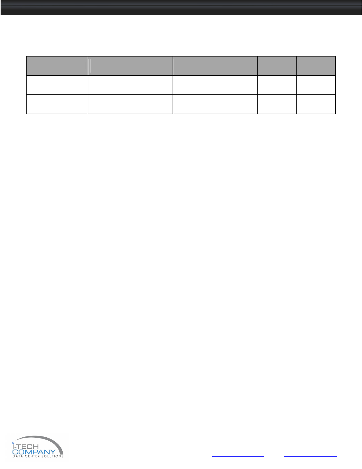
6.1 Dimensions
Model
NVP120 series
SNK120 series
Product Dimension
(W x D x H)
442 x 650 x 44 mm
17.4 x 25.6 x 1.73"
442 x 650 x 44 mm
17.4 x 25.6 x 1.73"
Packing Dimension
(W x D x H)
589 x 856 x 168 mm
23.2 x 33.7 x 6.6"
589 x 856 x 168 mm
23.2 x 33.7 x 6.6"
Net Weight Gross Weight
20 kg
44 lb
20kg
44 lb
Chapter 6
26 kg
57 lb
26 kg
57 lb
ii-Tech Company LLC TOLL FREE: (888) 483-2418 • EMAIL: [email protected] • WEB: www.iTechKVM.com
 Loading...