

Page 1

NetUP HDMI Encoder 8x
User’s manual
NMS Version: 2.2.5
SW: 0.17F
HW: 0.8
August 10, 2015
Page 2

CONTENTS
Chapter 1 Product Introduction ............................................................................................................. 1
1.1 Outline ................................................................................................................................................ 1
1.2 Main Features ................................................................................................................................... 1
1.3 Specifications .................................................................................................................................... 2
1.4 Principle Chart ................................................................................................................................... 3
1.5 Appearance and Illustration ............................................................................................................ 3
Chapter 2 Installation Guide .................................................................................................................. 5
2.1 Acquisition Check ............................................................................................................................. 5
2.2 Installation Preparation .................................................................................................................... 5
2.3 Wire’s Connection ............................................................................................................................ 7
2.4 Signal Cable Connection ................................................................................................................. 8
Chapter 3 Operation ............................................................................................................................. 11
3.1 Initializing ......................................................................................................................................... 11
3.2 General Setting ............................................................................................................................... 11
Chapter 4 SNMP Operation ............................................................................................................... 21
4.1 Installation ........................................................................................................................................ 22
4.2 Software Operation ........................................................................................................................ 22
4.3 NetUP HDMI Encoder 8x Operation ............................................................................................ 28
4.4 Other Settings ................................................................................................................................. 37
Chapter 5 Troubleshooting .................................................................................................................. 41
Chapter 6 Packing list ........................................................................................................................... 42
Page 3

NetUP HDMI Encoder 8x User’s Manual
1 / 44
Addr: 119311, Russia, Moscow, Ulofa Palme bldg.1, sect 7 Web: http://netup.tv
Chapter 1 Product Introduction
1.1 Outline
The NetUP HDMI Encoder 8x is our newest professional HD audio & video encoding and
multiplexing device with powerful functionality. It is equipped with 8 HDMI inputs
supporting MPEG-4 AVC/H.264 High Profile code format & main Profile code format and
1 ASI input. It can multiplex the ASI input TS and the 8 encoded SPTS to generate an
MPTS output with the inserted PSI/SI information. In conclusion, its high integrity and
cost-effective design, make this device widely used in variety of digital distribution
systems such as CATV digital head-end, satellite and terrestrial digital TV, etc.
1.2 Main Features
8 HDMI & 1 ASI inputs
H.264/AVC high profile level 4.0 video encoding
MPEG1 Layer 2 (HE-AAC (V2) or LC-AAC optional) audio encoding
PSI/SI editing and inserting
VBR or CBR video bitrate mode
720P, 1080I, 1080P HD video format
ASI output MPTS or 8 SPTS
IP Output MPTS and 8 SPTS
IP null packet filter
PID filter and transparent transport
Real-time output bit-rate monitoring
Update device through NMS port
LCD / keyboard operating, and network management (SNMP)
Page 4

NetUP HDMI Encoder 8x User’s Manual
2 / 44
Addr: 119311, Russia, Moscow, Ulofa Palme bldg.1, sect 7 Web: http://netup.tv
1.3 Specifications
Input
8 HDMI inputs
1 ASI input, BNC interface
Video
Resolution
1920×1080_60P, 1920×1080_50P
1920×1080_60i, 1920×1080_50i
1280×720_60P, 1280×720 _50P
720x576_50i, 720x480_59.95i
Encoding MPEG-4 AVC/H.264 high profile level 4.0
Bit-rate 0.8Mbps~19Mbps (each channel)
Rate Control CBR/VBR
GOP Structure IBBP
Advanced
Pretreatment
De-interlacing, Noise Reduction, Sharpening
Audio
Encoding MPEG-1 Layer II, HE-AAC (V2), LC-AAC
Sampling rate 48KHz
Resolution 24 bit
Bit-rate 64Kbps~384Kbps each channel
Multiplexing
1 ASI input multiplexed with local 8 channels of TS
Stream output
2*ASI output, BNC interface
MPTS and 8 SPTS over UDP, 1000 Base-T Ethernet
interface (UDP unicast / multicast)
System function
LCD/keyboard operating, NMS supporting
Chinese-English control interface
Ethernet software & hardware upgrade
Miscellaneous
Dimension (W× L× H) 440mm×410mm×44.5mm
Approx weight 4kg
Temperature 0~45℃(work), -20~80℃(Storage)
Power AC 100V-220V±10%, 50/60Hz
Consumption 25W
Page 5
NetUP HDMI Encoder 8x User’s Manual
3 / 44
Addr: 119311, Russia, Moscow, Ulofa Palme bldg.1, sect 7 Web: http://netup.tv
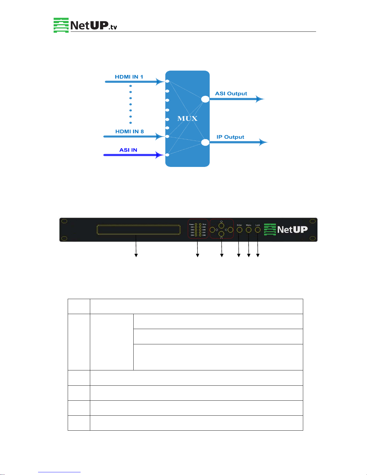
1.4 Principle Chart
1.5 Appearance and Illustration
Front Panel Illustration:
1 2 3 4 5 6
Indicate area: All indicators will light on when the device is on the current working state.
1 LCD Screen
2 Indicators
Power Indicator
TS In: Input Lock Indicator
CH1-CH8: When the program has been multiplexed, the
indicator will be on.
3 UP/ DOWN, LEFT/RIGHT Keys
4 Enter Key
5 Menu Key
6 Lock Key
Page 6
NetUP HDMI Encoder 8x User’s Manual
4 / 44
Addr: 119311, Russia, Moscow, Ulofa Palme bldg.1, sect 7 Web: http://netup.tv
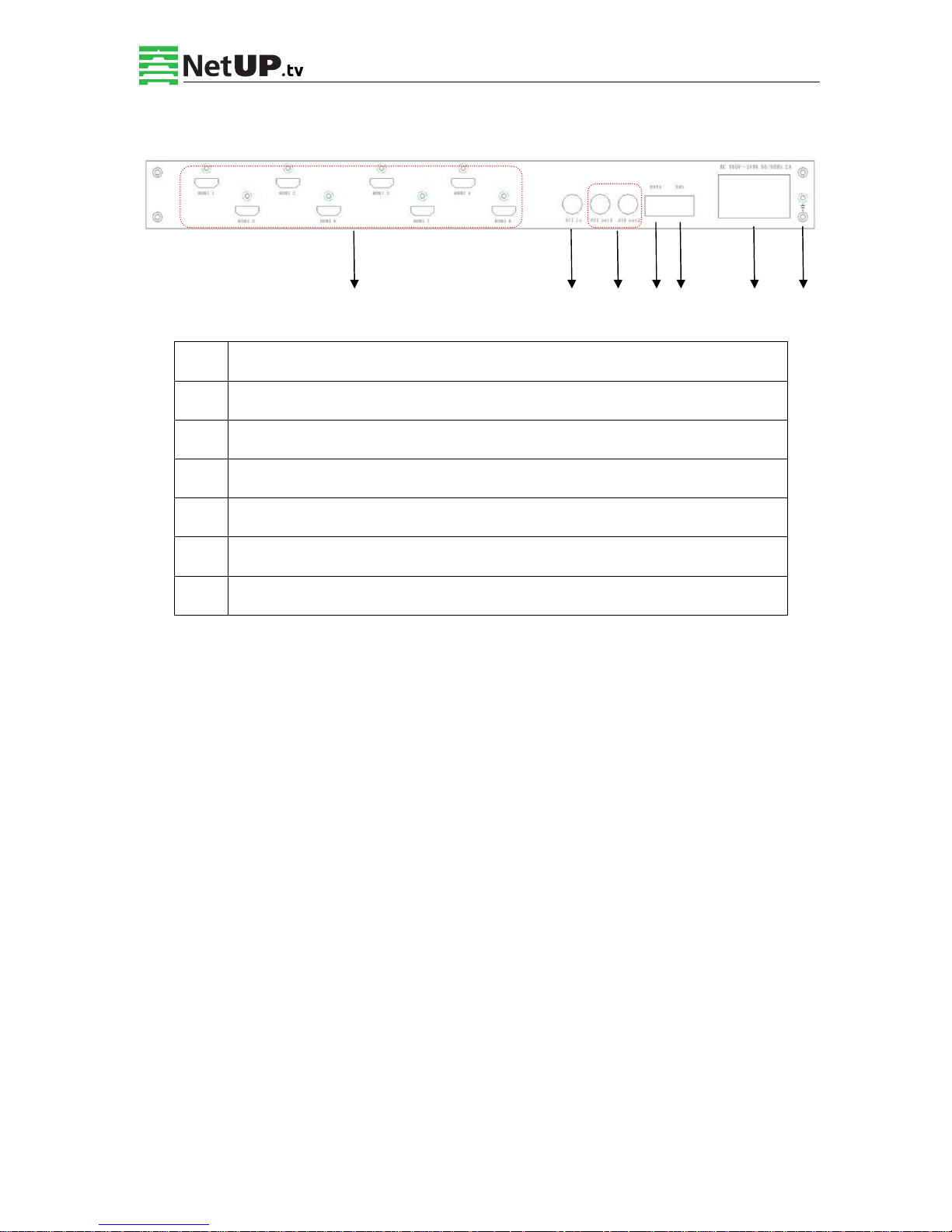
Rear Panel Illustration:
1 2 3 4 5 6 7
1 8 * HDMI Input Ports
2 ASI Input Port
3 2 * ASI Output Ports
4 Data Port (for IP Signal Output)
5 NMS (Network Management Port)
6 Power Switch and socket
7 Grounding Pole
Page 7
NetUP HDMI Encoder 8x User’s Manual
5 / 44
Addr: 119311, Russia, Moscow, Ulofa Palme bldg.1, sect 7 Web: http://netup.tv
Chapter 2 Installation Guide
2.1 Acquisition Check
When opening the package, it is necessary to check the items according to the packing list.
Normally it should contain the following items:
NetUP HDMI Encoder 8x
User’s Manual
HDMI Cable
ASI Cable
Power Cord
If any item is missing or mismatching with the list above, please contact your local dealer.
2.2 Installation Preparation
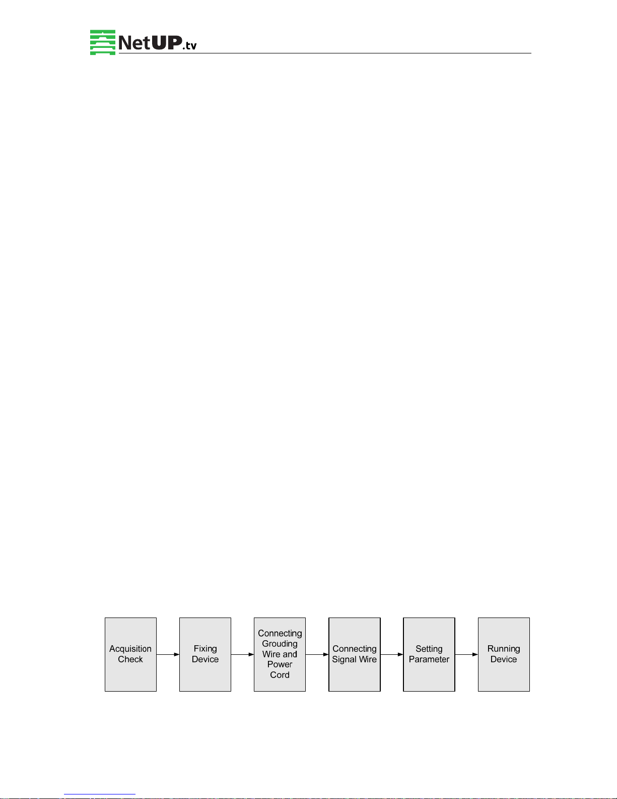
When installing the device, please follow the steps below. The details of the installation process
will be described later in this chapter. One can also use the rear panel chart during the
installation.
This chapter describes:
Checking the possible device loss or damage during the transportation
Preparing relevant environment for installation
Installing the NetUP HDMI Encoder 8x
Connecting signal cables
Connecting communication port (if it is necessary)
2.2.1 Device’s Installation Flow Chart:
Page 8

NetUP HDMI Encoder 8x User’s Manual
6 / 44
Addr: 119311, Russia, Moscow, Ulofa Palme bldg.1, sect 7 Web: http://netup.tv
2.2.2 Environment Requirements
Item Requirement
Machine Hall Space
When installing a machine frame array in one machine hall, the
distance between 2 rows of machine frames should be 1.2~1.5m
and the distance against wall should be no less than 0.8m.
Machine Hall Floor
Electric Isolation, Dust Free
Volume resistivity of ground anti-static material:
1X10⁷~1X10
10
,Grounding current limiting resistance: 1M
(Floor bearing should be greater than 450Kg/㎡)
Environment
Temperature
5~40℃(sustainable ),0~45℃(short time),
installing air-conditioning is recommended
Relative Humidity 20%~80% sustainable 10%~90% short time
Pressure 86~105KPa
Doors & Windows
Install rubber strip for sealing door-gaps and dual level glasses
for window
Walls May be covered with wallpaper, or dark paint.
Fire Protection Fire alarm system and extinguisher
Power
Requiring device power, air-conditioning power and lighting
power are independent to each other. Device power requires AC
power 220V 50Hz. Please carefully check before running.
2.2.3 Grounding Requirement
All function modules’ good grounding designs are the basis of reliability and stability of
electronic devices. It is the most important guarantee of surge protection and interference
rejection. Therefore, the system must be grounded.
Coaxial cable’s outer conductor and isolation layer should keep proper electric conducting
with the metal housing of device.
Grounding conductor must adopt copper conductor in order to reduce high frequency
impedance, and the grounding wire must be as thick and short as possible.
Make sure the 2 ends of grounding wire conduct electricity and are not rusty.
It is prohibited to use any other devices as a part of grounding electric circuit
The area of the conduction between grounding wire and device’s frame should be no less
Page 9

NetUP HDMI Encoder 8x User’s Manual
7 / 44
Addr: 119311, Russia, Moscow, Ulofa Palme bldg.1, sect 7 Web: http://netup.tv
than 25mm2.
2.2.4 Frame Grounding
All the machine frames should be connected with protective copper strip. The grounding wire
should be as short as possible and should avoid circling. The area of the conduction between
grounding wire and grounding strip should be no less than 25mm2.
2.2.5 Device Grounding
Connect the device’s grounding rod to frame’s grounding pole with copper wire.
2.3 Wire’s Connection
The grounding wire conductive screw is located at the right of the rear panel, and the power
switch, fuse, power supply socket are just beside ,whose order goes like this, power switch is
on the left ,power supply socket is on the right and the fuse is just between them.
Connecting the Power Cord:
Connect one end to the power supply socket, and the other end to the AC power.
Connecting Grounding Wire:
When the device solely connects to protective ground, it should adopt independent way,
say, share the same ground with other devices. When the device adopts united way, the
grounding resistance should be smaller than 1Ω.
Caution:
Before connecting power cord to the NetUP HDMI Encoder 8x, set the power
switch to “OFF” position.
Page 10

NetUP HDMI Encoder 8x User’s Manual
8 / 44
Addr: 119311, Russia, Moscow, Ulofa Palme bldg.1, sect 7 Web: http://netup.tv
2.4 Signal Cable Connection
The signal connections include the connection of input signal cable and the connection of
output signal cable. The details are as follows:
2.4.1 HDMI input cable illustration:
2.4.2 ASI output cable illustration:
2.4.3 Network Cable illustration (CAT5):
Page 11
NetUP HDMI Encoder 8x User’s Manual
9 / 44
Addr: 119311, Russia, Moscow, Ulofa Palme bldg.1, sect 7 Web: http://netup.tv
2.4.4 HDMI input interface connection
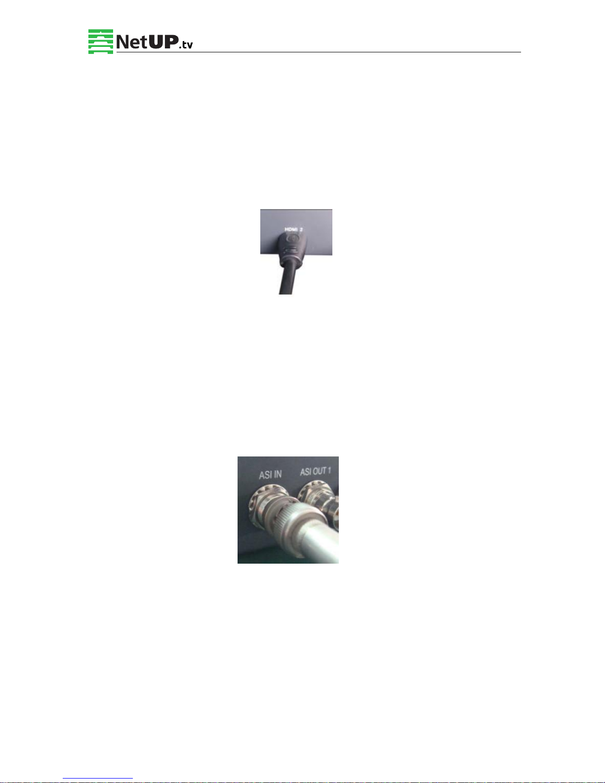
Find the HDMI interface on the device according to the connector mark described on the rear
panel illustration, and then connect the HDMI cable (in the accessories). One end is connected
to the head-end equipment while the other end to the encoder’s HDMI input port. The
encoder’s HDMI input port (HDMI1…HDMI8) and an HDMI cable connected to it, illustrated
as follows:
2.4.5 ASI output interface connection
Find the ASI output interface on the device according to the connector mark described on the
rear panel illustration, and then connect the ASI cable (in the accessories). Connect one end to
the encoder’s ASI out connector (ASI1, ASI2) and the other end to the TS stream multiplexer or
modulator’s ASI input port. The encoder’s ASI output interface and a cable, connected to it,
illustrated as follows:
Page 12
NetUP HDMI Encoder 8x User’s Manual
10 / 44
Addr: 119311, Russia, Moscow, Ulofa Palme bldg.1, sect 7 Web: http://netup.tv
2.4.6 IP Output Interface connection
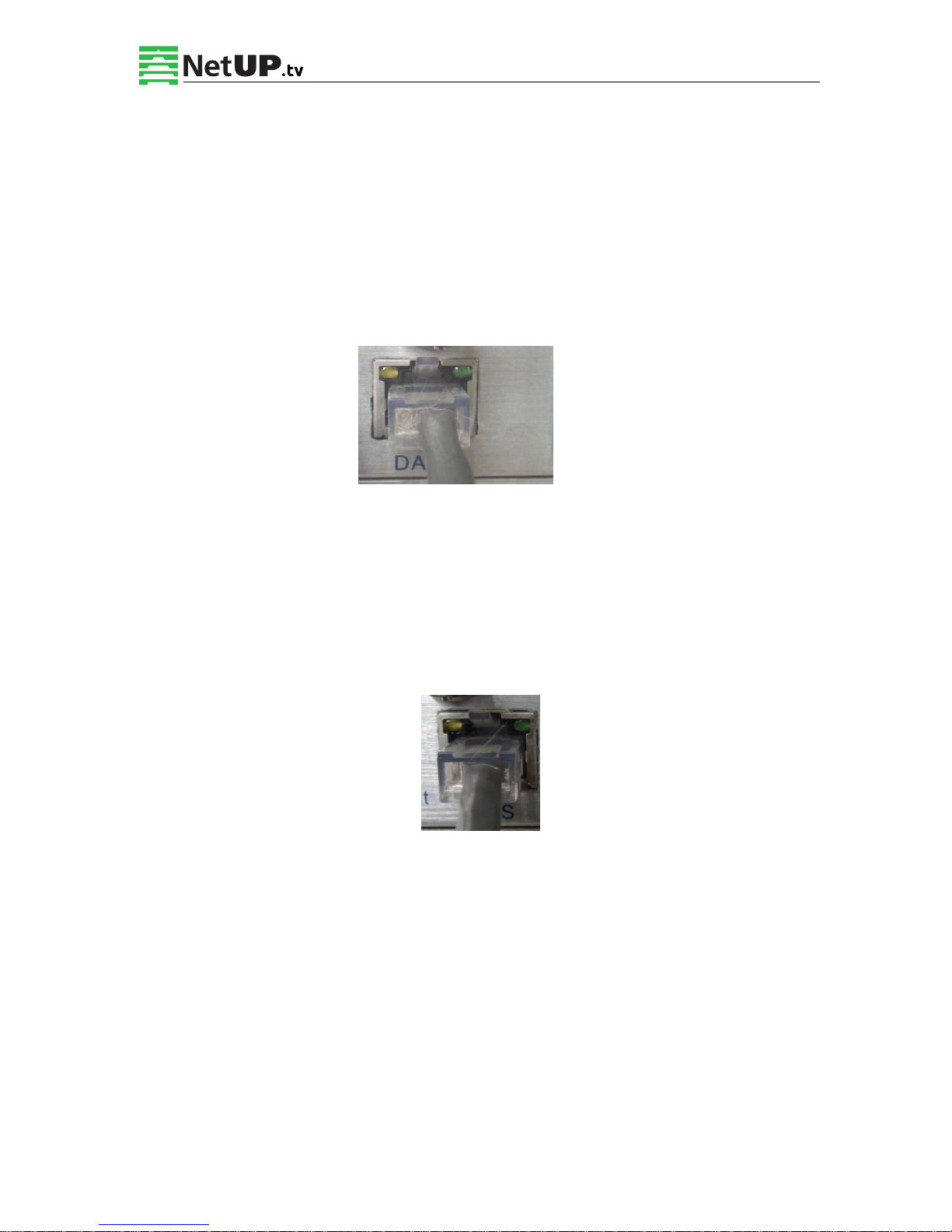
Find the DATA interface on the device according to the connector mark described on the rear
panel illustration, and then connect the network cable (CAT5). Connect one end of the network
cable to the encoder’s DATA output connector, and the other end to the TS stream multiplexer
IP input port or other device which can input IP signal (the IP input should support at least 1
Gb/s transmission rate). The encoder’s DATA interface connection is illustrated as follows:
2.4.7 NMS Connection
Find the NMS interface on the device according to the connector mark described on the rear
panel illustration, and then connect the network cable (CAT5). Connect one end of the network
cable to the encoder’s NMS connecter, and the other end to your PC. The encoder’s NMS
connection is illustrated as follows:
Page 13

NetUP HDMI Encoder 8x User’s Manual
11 / 44
Addr: 119311, Russia, Moscow, Ulofa Palme bldg.1, sect 7 Web: http://netup.tv
Chapter 3 Operation
NetUP HDMI Encoder 8x’s front panel has the user interface. Before operating, user can decide
whether directly use the default setting or customize the input and output parameters setting.
Here is a detailed description of these operations:
Keyboard Functions Description:
ENTER: Activates the parameters that need to be modified, or confirms the changes after
modification.
MENU: Cancels unsaved changes to currently selected value, resets to previous settings and
returns to previous menu.
LEFT/RIGHT: Moves the “►” to choose or set the parameters.
UP/DOWN: Modify activated parameter or page up/down when a parameter is not activated.
LOCK: Locks the screen / cancels the locked state. After pressing lock key, the system will ask
if you want to save the current changes. If not, the LCD will display the current configuration
state.
At the “Factory Configuration” page, press “ENTER” key to restore the factory default
configuration.
3.1 Initializing
After powering on the device,it will take a few seconds to initialize the system, and then the
LCD will show the device’s name and output real-time bit-rate in the first row, while the 8
channels’ respective input video resolution, frame rate and real-time encoding bit-rate in the
second row in turn. It shows as below:
3.2 General Setting
By pressing LOCK key, one can enter the main menu and set the input and output parameters in
Page 14
NetUP HDMI Encoder 8x User’s Manual
12 / 44
Addr: 119311, Russia, Moscow, Ulofa Palme bldg.1, sect 7 Web: http://netup.tv
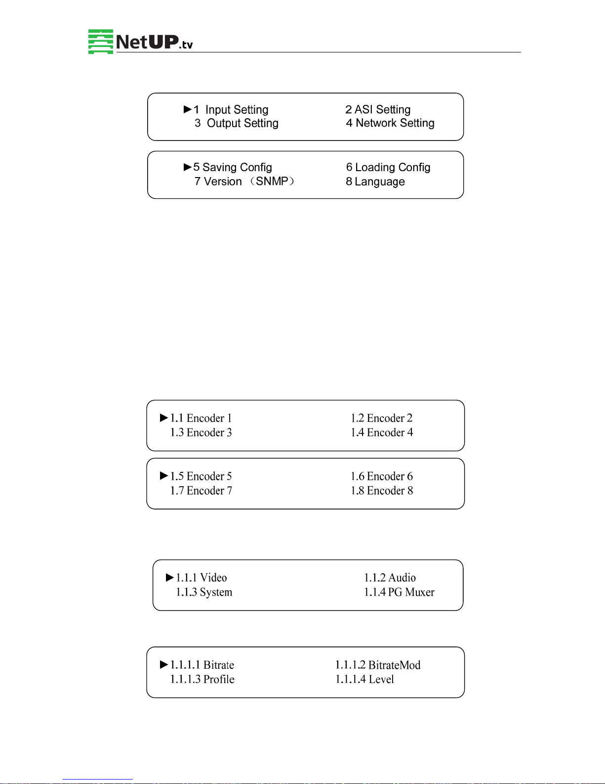
the following editing interfaces, the LCD will display the following pages:
The option with “►” is the current selection, press the ENTER key to enter the specified
submenu to modify the device parameters.
3.2.1 Input Setting
Under this menu, users can enter the corresponding encoding channel to set the relevant audio
and video input parameters, and select programs to multiplex. The LCD will display 8
submenus from Encoding Channel 1 to Encoding Channel 8. The setting principle is the same
for Encoding Channel 1-8, so here this manual takes one channel as an example. After pressing
the enter key, the LCD will display the following pages:
Once you enter a submenu, the screen will show the following pages, and then one can enter
the corresponding interface to modify its parameters.
3.2.1.1 Video Setting
Bitrate
Page 15
NetUP HDMI Encoder 8x User’s Manual
13 / 44
Addr: 119311, Russia, Moscow, Ulofa Palme bldg.1, sect 7 Web: http://netup.tv
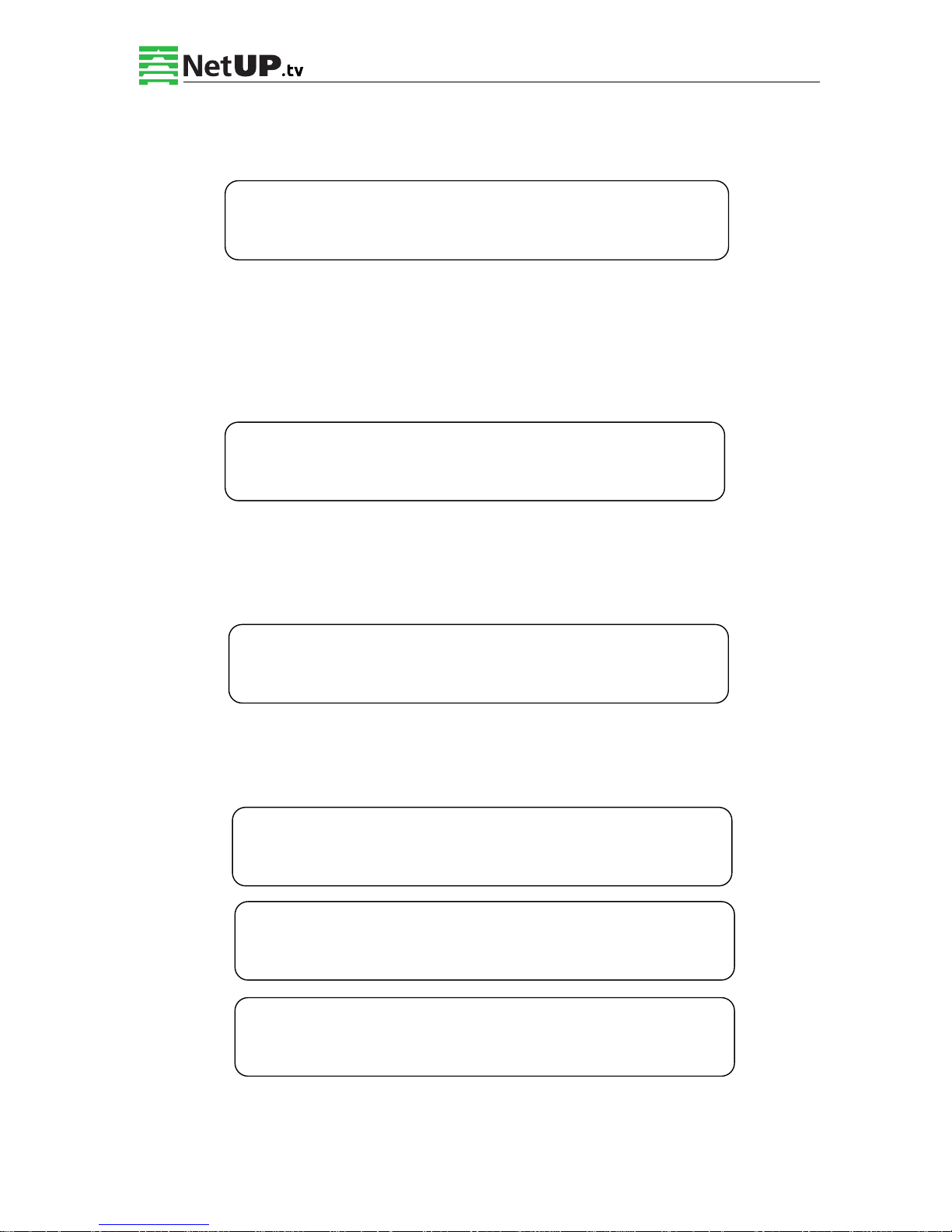
Press Enter to modify relevant parameter of encoding rate (adjustable range: 0.8M~19M), the
specific steps are displayed as follows:
Bitrate Mode
Choose CBR & VBR in this menu. CBR (Constant Bit-rate) means that the bit-rate will be a
constant value. VBR (Variable Bit-rate) means that the bit-rate will change along with the video
scene changing.
Profile
Select the configuration of the H.264 profile at this menu. There are H.264 High Profile code
format and main Profile code format.
Level
Select the H.264 level at this menu. The option in brackets is the current choice.
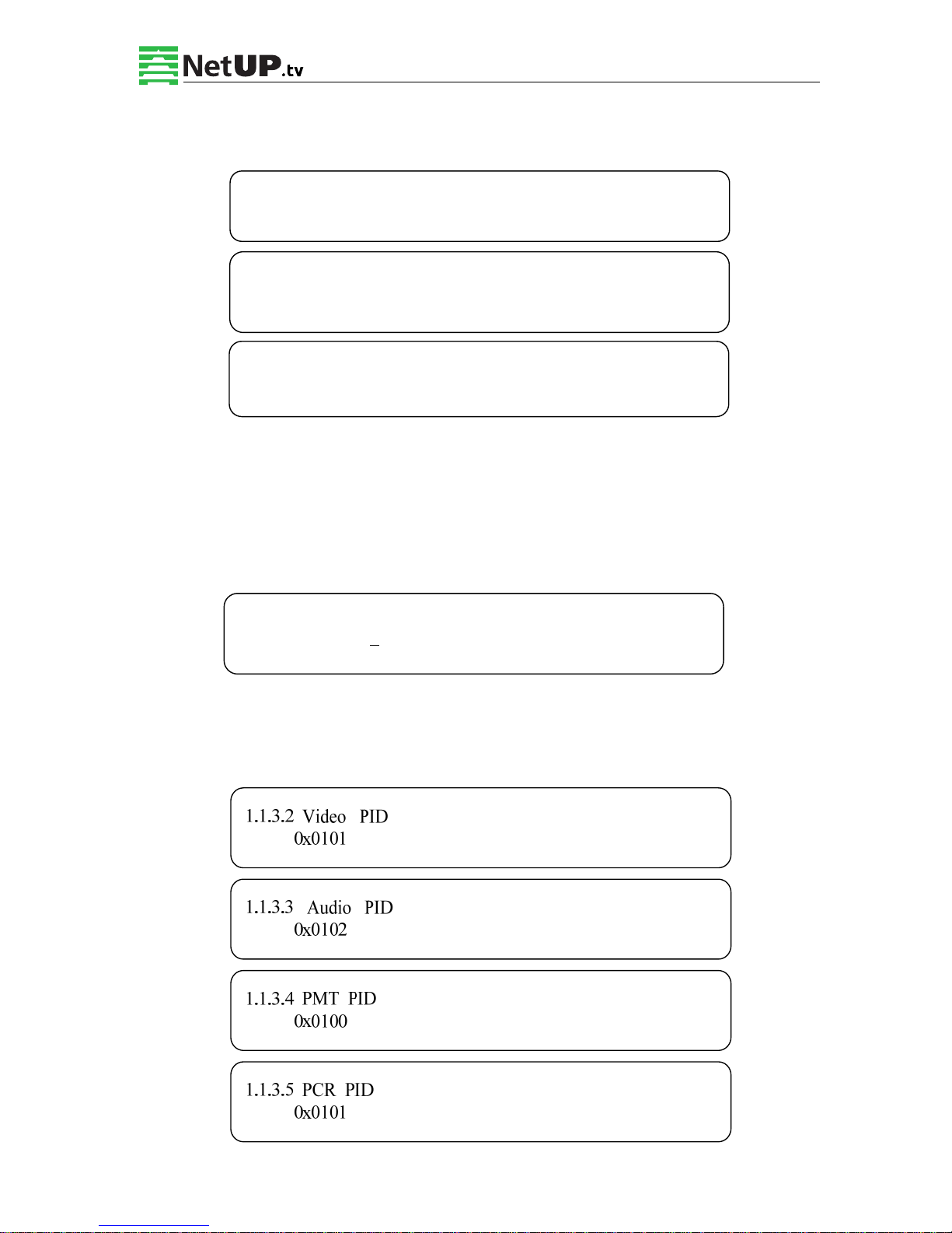
3.2.1.2 Audio Setting
1.1.1.1 Bitrate
8.000Mbps
1.1.1.2 BitrateMod 01/01
[CBR] VBR
1.1.1.3 Profile 01/01
[HIGH] MAIN
1.1.1.4 Level 01/03
[1.2] 1.3 2.0 2.1
1.1.1.4 Level 02/03
[2.2] 3.0 3.1 3.2
1.1.1.4 Level 03/03
[4.0] 4.1 4.2
Page 16
NetUP HDMI Encoder 8x User’s Manual
14 / 44
Addr: 119311, Russia, Moscow, Ulofa Palme bldg.1, sect 7 Web: http://netup.tv
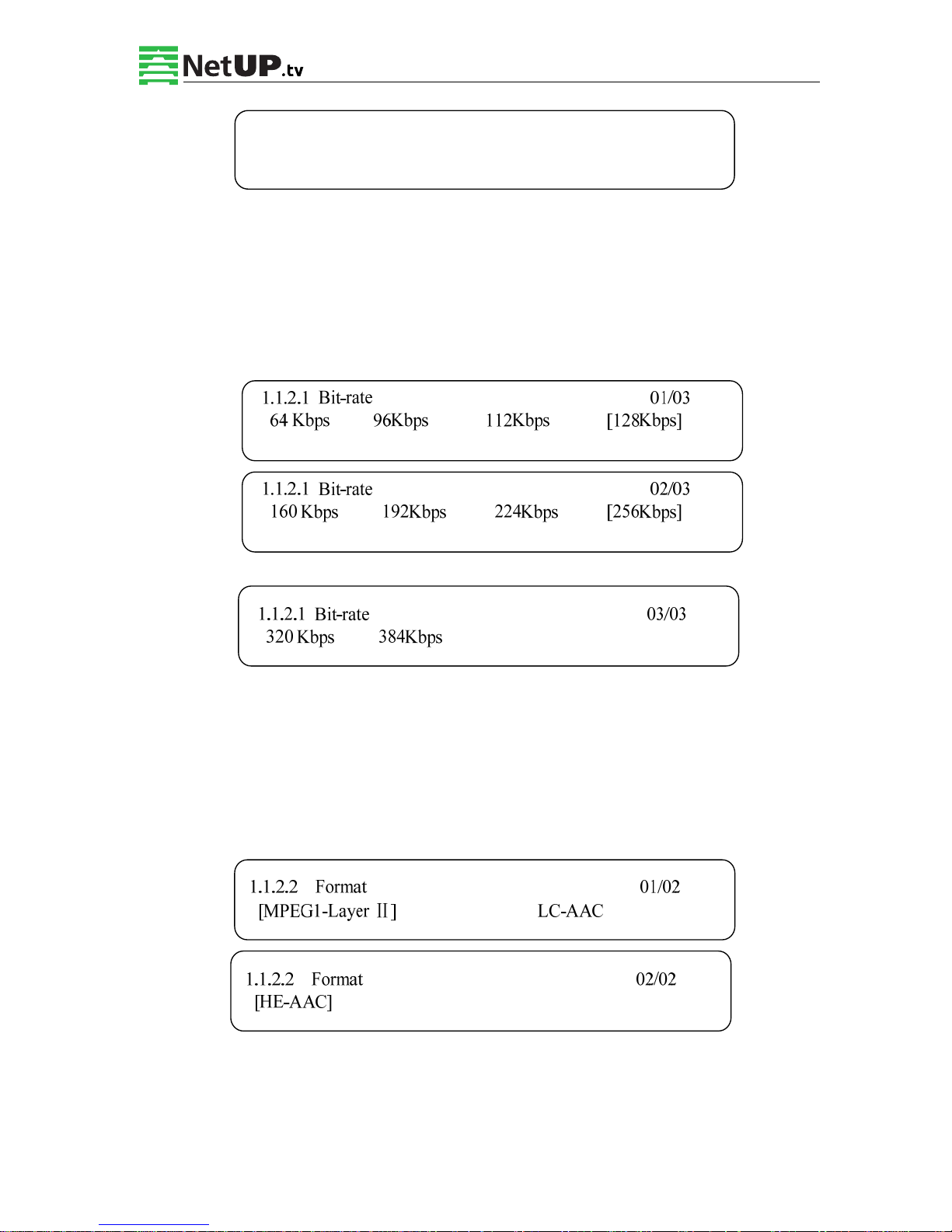
Audio Bit Rate Setting
Set the input audio bit-rate by pressing Enter to enter the main editing screen. And there are:
64Kbps, 96Kbps, 112Kbps, 128Kbps, 160Kbps, 192Kbps, 224Kbps, 256 Kbps, 320Kbps, and
384Kbps options. After modification, press Enter again to apply changes. The LCD will display
the following pages:
Audio Format Setting
AAC: Advanced Audio Coding
Set the input audio format on this screen, and the 3 options are MPEG1 Layer Ⅱ, LC-AAC,
and HE-AAC. When you enter the main editing menu, the LCD will display the following
page:
1.1.2.1 Bit Rate 1.1.2.2 Format
Page 17
NetUP HDMI Encoder 8x User’s Manual
15 / 44
Addr: 119311, Russia, Moscow, Ulofa Palme bldg.1, sect 7 Web: http://netup.tv
3.2.1.3 System Settings
On this screen, one can set the corresponding system parameters, after setting those parameters,
press Enter to apply the changes.
Program Number Setting
Set the program number by pressing Enter to enter this submenu. The LCD will display the
following:
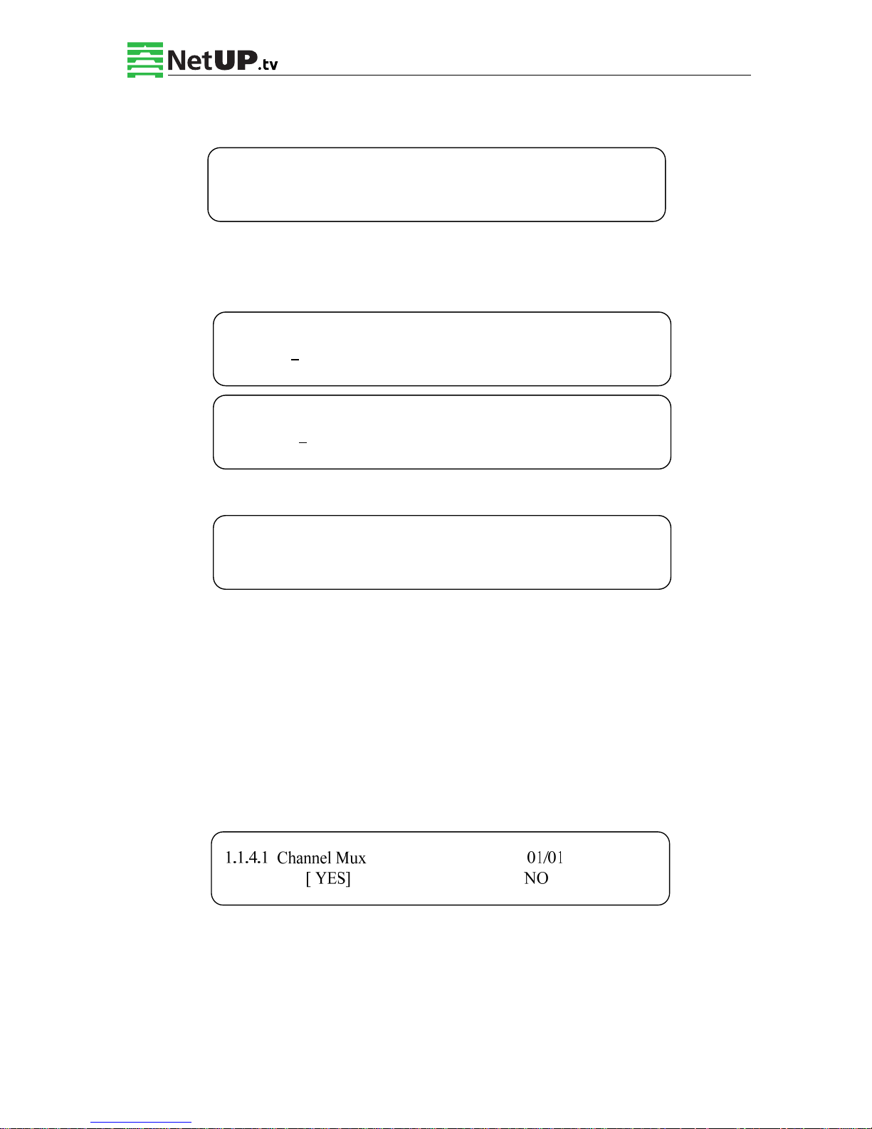
Video/Audio/PMT/PCR PID Settings
Set these parameters by pressing Enter to enter these submenus. The LCD will display the
following pages, and the maximum PID number cannot exceed 0x1fff.
►1.1.3.1 Prog Number 1.1.3.2 Video PID
1.1.3.3 Audio PID 1.1.3.4 PMT PID
►1.1.3.5 PCR PID 1.1.3.6 IP Enable
1.1.3.7 Out Address 1.1.3.8 Out Port
►1.1.3.9 Null PKT
1.1.3.1 Program Number
0x0101
Page 18
NetUP HDMI Encoder 8x User’s Manual
16 / 44
Addr: 119311, Russia, Moscow, Ulofa Palme bldg.1, sect 7 Web: http://netup.tv
IP Enable
Out Address/Out Port Setting
Modify the out address and out port:
Null Packet
Choose YES (filter the null packet) or NO (don’t filter the null packet).
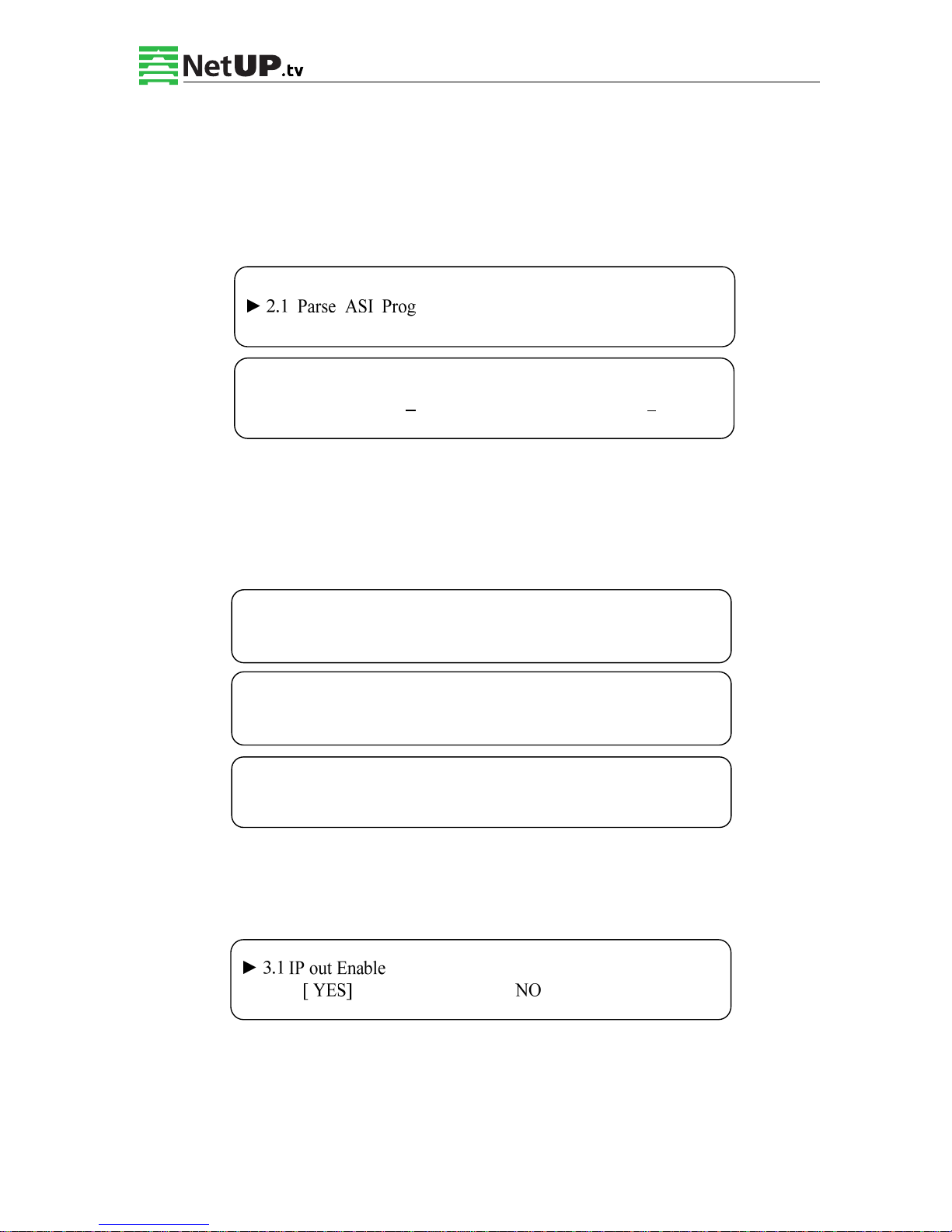
3.2.1.4 Program Mux Setting
Decide whether to open the multiplexing function of the device.
Channel Mux
Under this interface, you can decide whether to multiplex the channel encoding stream. YES
means that the device multiplexes the encoding stream into the MPTS, while NO means that the
output program is SPTS. The LCD will display the following pages after pressing Enter.
1.1.3.6 IP Enable 01/01
YES [NO]
1.1.3.7 Out Address
224.002.002.002
1.1.3.8 Out Port
1002
1.1.3.9 Null Packet 01/01
YES [NO]
Page 19
NetUP HDMI Encoder 8x User’s Manual
17 / 44
Addr: 119311, Russia, Moscow, Ulofa Palme bldg.1, sect 7 Web: http://netup.tv
3.2.2 ASI Setting
Check the number of ASI input programs on this screen, the LCD will display the following
page. Prog: 006 means that the number of input programs is 6 and Out:003 means that 3 of
those 6 programs are multiplexed.
3.2.3 Output Setting
Press Enter in the main editing screen, to set the device output parameters. The LCD will
display the following page:
3.2.3.1 IP Out Enable
This is a new function of this encoder, user can decide whether to open the IP output function
by pressing Enter in this menu, and the LCD will show the following page:
2.1 Parse ASI Prog Prog: 006 Out: 003
► 001 HK1 √ 002 HK2 X
► 3.1 IP Out Enable 3.2 IP Out Address
3.3 IP Out Port 3.4 Trans Stream ID
► 3.5 Output Stream 3.6 ASI Output
3.7 UTC Time Config 3.8 Null PKT
► 3.9 TS Package Num
Page 20
NetUP HDMI Encoder 8x User’s Manual
18 / 44
Addr: 119311, Russia, Moscow, Ulofa Palme bldg.1, sect 7 Web: http://netup.tv
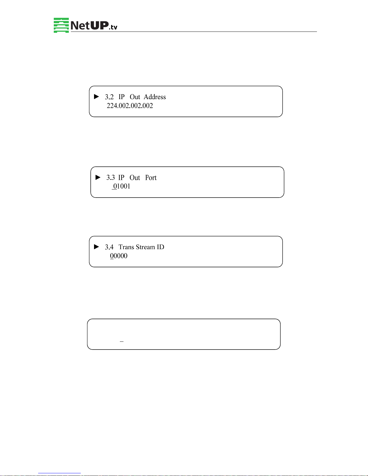
3.2.3.2 IP Out Address
If you enable the IP output function, then you can setup the device’s IP address in the following
screen. After you press the Enter, the LCD will display the following page:
3.2.3.3 IP Out Port
In this menu set the encoder IP output port number by pressing the Enter to enter the main
editing screen:
3.2.3.4 Trans Stream ID
Set the device TS ID in this screen after pressing the Enter to enter the main editing page.
3.2.3.5 Output Stream
You can modify the bit rate of the output stream in this screen after pressing Enter to enter the
main editing page:
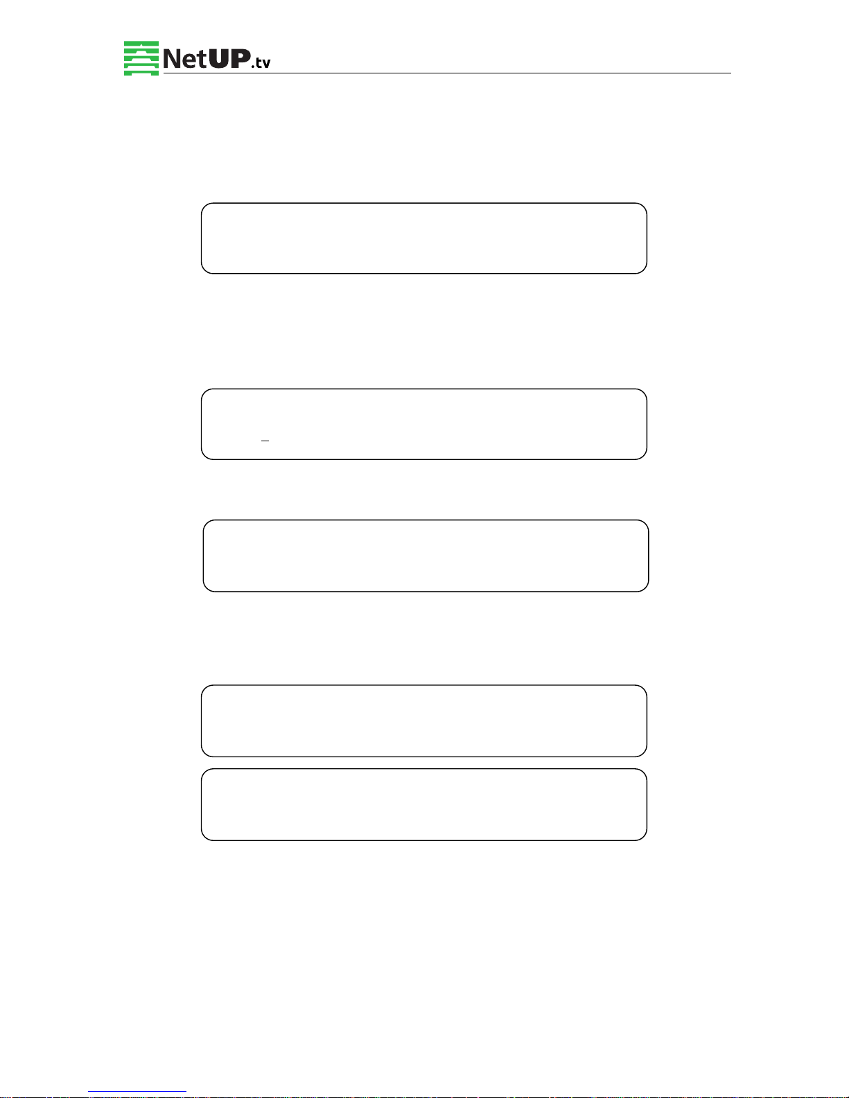
3.5 Output Stream
040.000 Mbps
Page 21
NetUP HDMI Encoder 8x User’s Manual
19 / 44
Addr: 119311, Russia, Moscow, Ulofa Palme bldg.1, sect 7 Web: http://netup.tv
3.2.3.6 ASI Output
One can set the ASI output in this screen under this menu, and there are 9 options: MPTS,
Channel 1-8.
3.2.3.7 UTC Time
UTC refers to Universal Time Coordinated. Enter this menu to set the time as needed and it will
then generate the TDT table and show it in the user’s STB.
3.2.3.8 Null Packet
3.2.3.9 TS Package Num
One can set the amount of TS packages by entering the screen below:
3.6 ASI Output 01/03
[MPTS] Channel 1 Channel 2 Channel 3
3.7 UTC Time Configuration
2012-01-29 15:45:03
3.8 Null Packet 01/01
YES [NO]
3.9 TS Package Num 01/02
1 2 3 [4]
3.9 TS Package Num 02/02
[5] 6 7
Page 22
NetUP HDMI Encoder 8x User’s Manual
20 / 44
Addr: 119311, Russia, Moscow, Ulofa Palme bldg.1, sect 7 Web: http://netup.tv
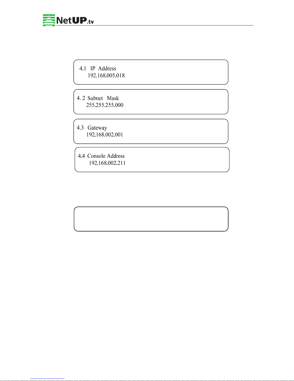
3.2.4 Network Setting
Set the network parameters by pressing Enter, the LCD will display the following screens:
The MAC address is read-only in the keyboard operation interface, so one can only check the
physical address under this interface, and the modification must be done with the network
updating tools.
NOTE: The MAC address is unique, and cannot be modified. When the MAC
address is ffffffffffff, users must modify the address through special software,
otherwise, the IP output data will be filtered out when the IP stream passes
through a router.
4.5 MAC Address
201012345679
Page 23
NetUP HDMI Encoder 8x User’s Manual
21 / 44
Addr: 119311, Russia, Moscow, Ulofa Palme bldg.1, sect 7 Web: http://netup.tv
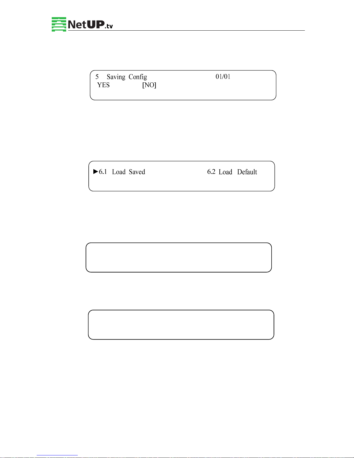
3.2.5 Saving Configuration
To save the modifications, press Enter, and the LCD will show the following screen:
3.2.6 Loading Configuration
In this screen, one can select the modified configuration and the factory default configuration.
One can enter the corresponding menu to select the configuration. The LCD will show the
following screen:
3.2.7 Version
Check the device software version and hardware version, and the LCD will show the following
screen when you press Enter:
3.2.8 Language
Select the language in this submenu:
8 Language
中文 [ENGLISH]
8 in 1 Encoder
SW 0.17F HW 08
Page 24
NetUP HDMI Encoder 8x User’s Manual
22 / 44
Addr: 119311, Russia, Moscow, Ulofa Palme bldg.1, sect 7 Web: http://netup.tv
Chapter 4 SNMP Operation
Network Management System
SNMP Network management system is applied to digital TV equipment operation, control,
management, parameters setting, etc. It allows centralized control of the digital TV equipment
over the network.
4.1 Installation
The software doesn’t need special installation. User can just open the folder SnmpNMS x.xy.z,
find the icon and double click it to pop up the login interface.
4.2 Software Operation
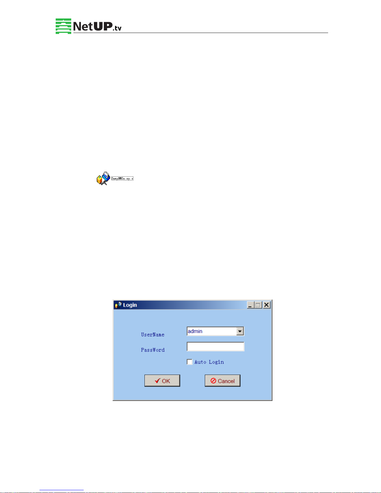
4.2.1 Login Interface
A login interface will pop up firstly when the software is running and give user prompts to
input user name and password (The default user name is admin and no password. User can add
users and passwords as needed. Details please refer to 4.4.3 in 4.4 Other Settings.). The menu
shows as follows:
User can login the NMS by pressing OK key after inputting user name. Upon the inputs, the
software will verify them with database record automatically and the main interface will
appear.
Page 25
NetUP HDMI Encoder 8x User’s Manual
23 / 44
Addr: 119311, Russia, Moscow, Ulofa Palme bldg.1, sect 7 Web: http://netup.tv
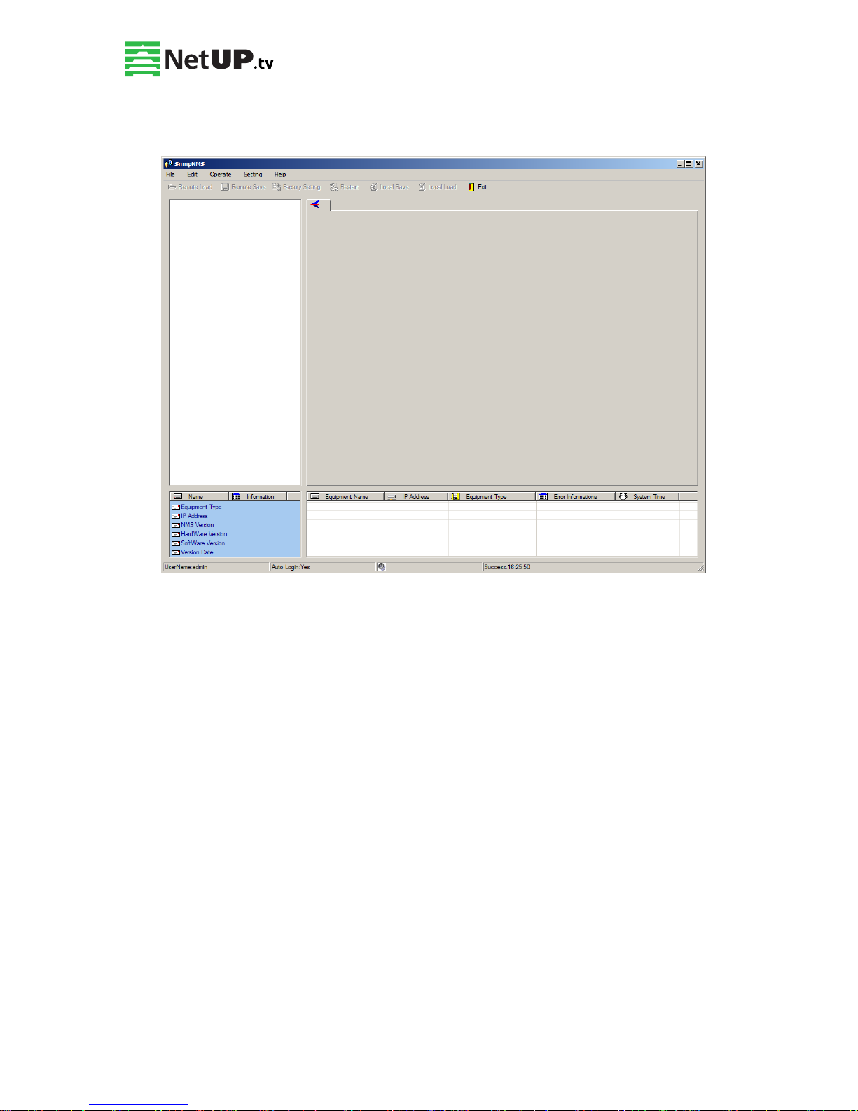
4.2.2 Main Interface
User can create a device node tree in the left column by adding, modifying and deleting the
device node. This software provides a powerful node operation function, and the user can edit
various parameters in the device tree for management and classification.
Page 26
NetUP HDMI Encoder 8x User’s Manual
24 / 44
Addr: 119311, Russia, Moscow, Ulofa Palme bldg.1, sect 7 Web: http://netup.tv
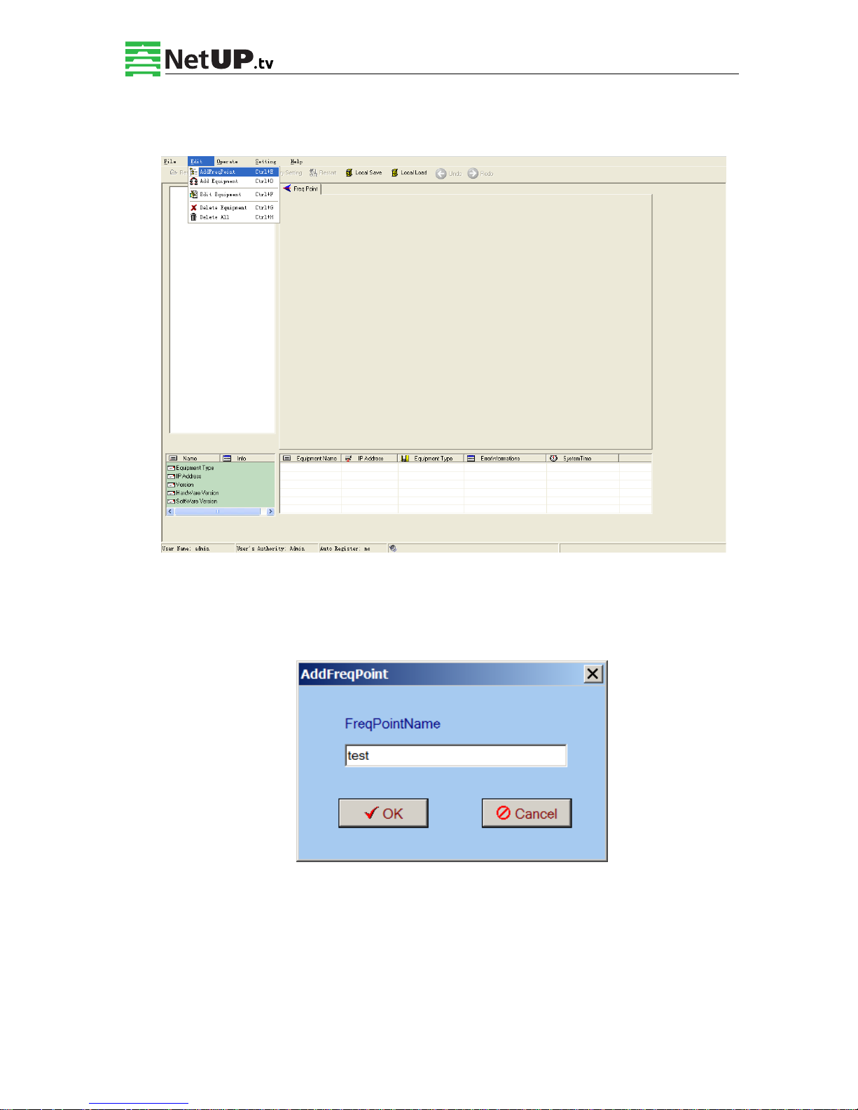
4.2.3 Adding Frequency Point
The Add Freq Point dialog box popes up when the user clicks the Add Freq Point item in the
Edit pull down menu on the menu row. The device will confirm the given frequency while user
clicks OK.
User can also click right mouse key to pop up the short-cut menu in device tree or in the left
blank column, then the corresponding dialog box will pop up by choosing Add Main Freq
Point. The device will confirm the given frequency while user clicks OK.
Page 27
NetUP HDMI Encoder 8x User’s Manual
25 / 44
Addr: 119311, Russia, Moscow, Ulofa Palme bldg.1, sect 7 Web: http://netup.tv
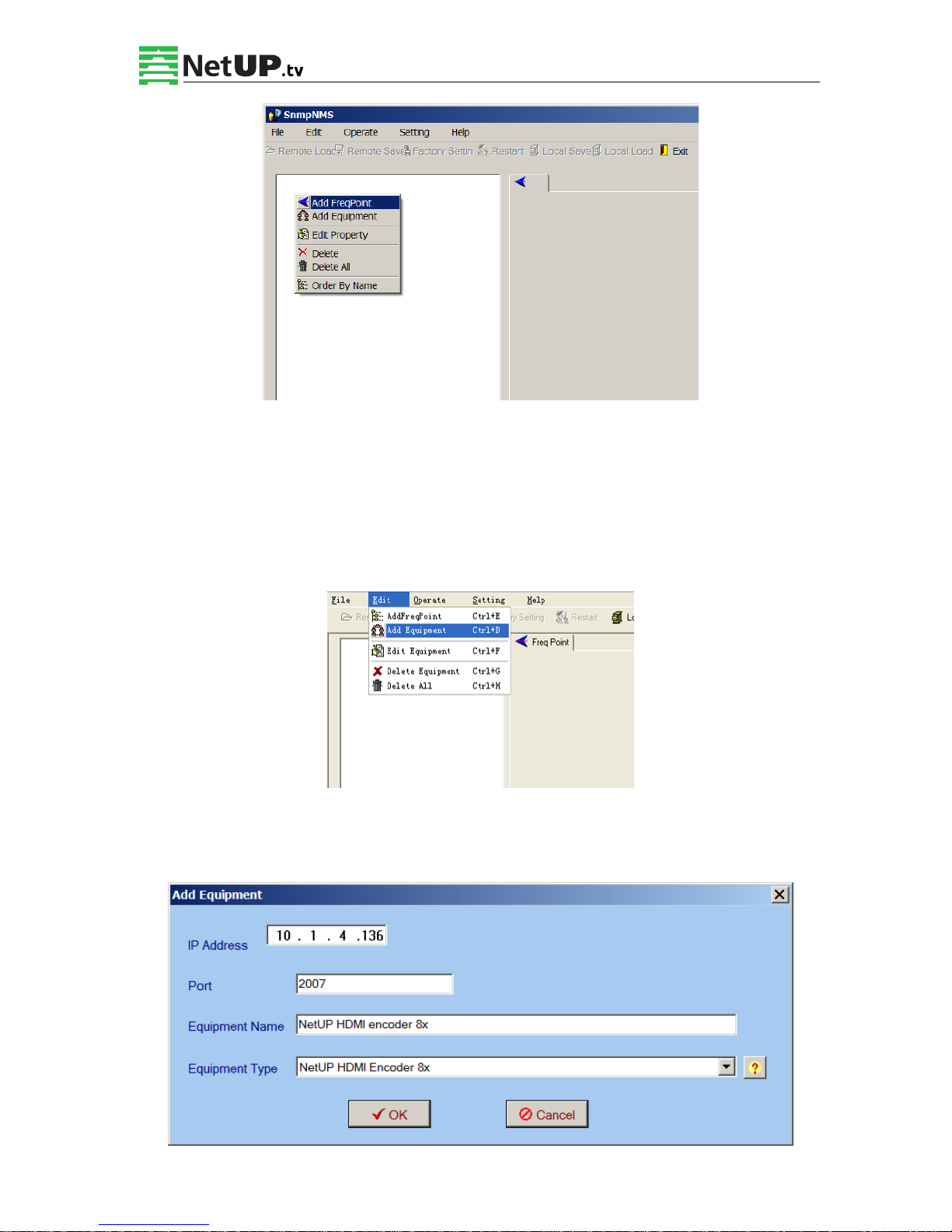
4.2.4 Adding Equipment under Given Frequency Point
User should choose the frequency point in advance, and then the dialog box of Add Equipment
will pop up when user clicks “Add Equipment” item in the Edit pull down menu on the menu
row.
4.2.5 Edit Equipment Interface
Page 28
NetUP HDMI Encoder 8x User’s Manual
26 / 44
Addr: 119311, Russia, Moscow, Ulofa Palme bldg.1, sect 7 Web: http://netup.tv
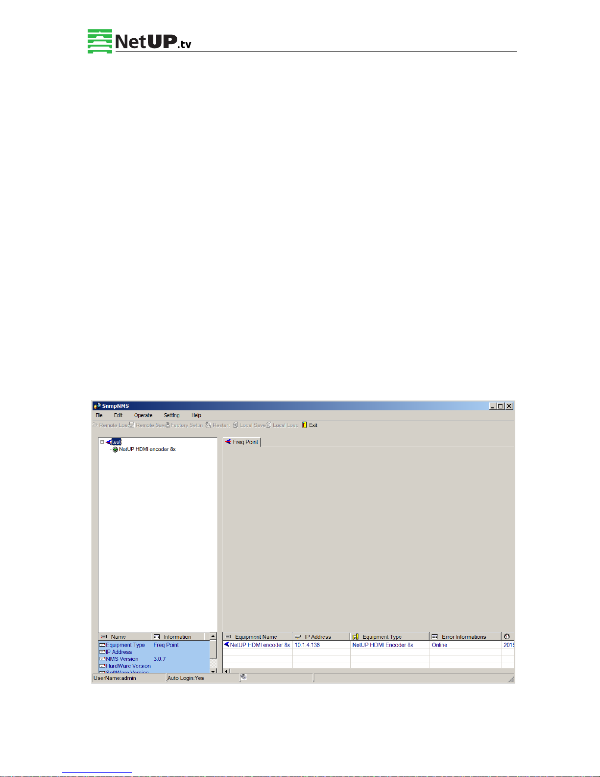
User should follow the steps as below:
Inputting the device IP Address
Inputting the port
Inputting the Equipment Name
Choosing the connected equipment type in drop down list of “Equipment Type” by
clicking the “▼” Or Click “?” to auto search the type of device.
NOTE:
1. The default IP for NetUP HDMI encoder 8x is 192.168.0.136, also you can check its IP
address in the front panel of device in case the IP changed unexpected.
2. The PC IP address and device IP address should be in the same network. For example the
Device IP is 192.168.2.136, sub mask is 255.255.255.0. So the PC IP address should be
192.168.2.X (1<X<255), sub mask is 255.255.255.0. User can use ping command to
confirm these two are in same network or not.
Click OK, it will appear as below:
Page 29
NetUP HDMI Encoder 8x User’s Manual
27 / 44
Addr: 119311, Russia, Moscow, Ulofa Palme bldg.1, sect 7 Web: http://netup.tv
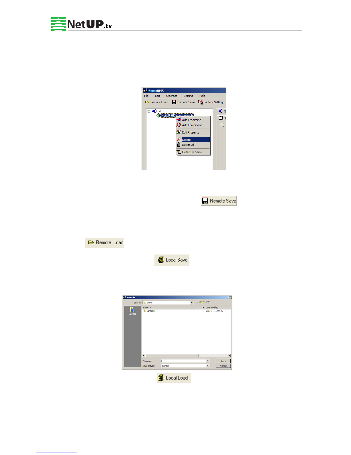
4.2.6 Delete Equipment
User can choose the equipment to be deleted in the left column, and then click the “delete” item
in the pull down menu which appears by clicking the right mouse key.
4.2.7 Save Configuration
After finishing all the parameters setting, user can click button on the toolbar to
save the modifications to the device’s flash, while user can also reload the saved parameters
from device’s flash and refresh the device’s parameters setting according to the loaded values
by clicking
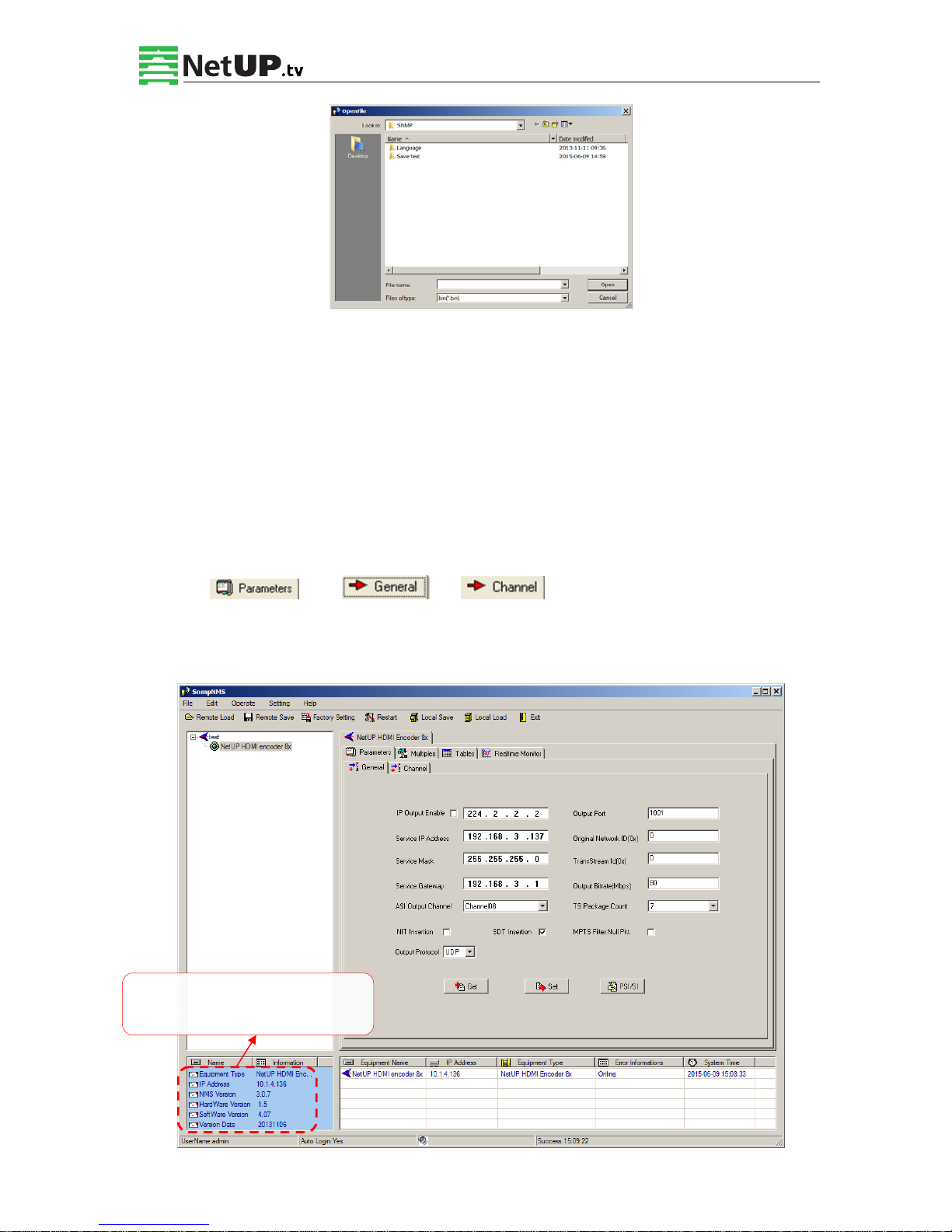
Alternatively, user can also click the
button on the toolbar to popup the “save
file” dialog box, which gives prompts to save all the device’s parameters as binary files in the
computer’s hard disk.
Similarly, user can choose to click the button on the toolbar to popup the read
file dialog box, to read the stored binary file and set the device’s parameters according to the
loaded binary files.
Page 30
NetUP HDMI Encoder 8x User’s Manual
28 / 44
Addr: 119311, Russia, Moscow, Ulofa Palme bldg.1, sect 7 Web: http://netup.tv
4.3 NetUP HDMI Encoder 8x Operation
User can choose the encoder in the device tree; the procedure will display the encoder interface
in operating area. The interface is mainly composed of encoding video parameters, audio
parameters and the encoding system parameters, output parameters and etc.
4.3.1 Parameters Setting
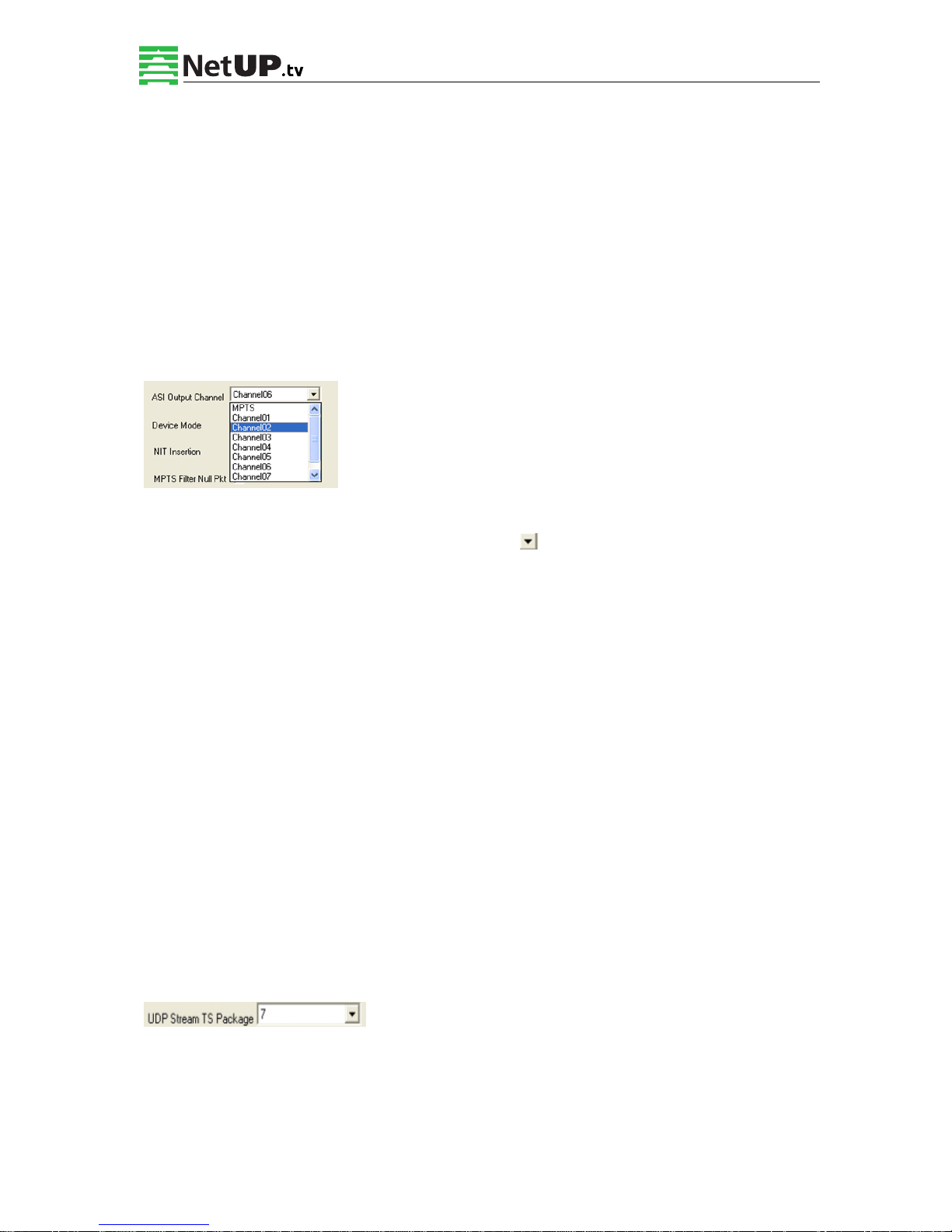
Users can click Equipment Name on the node tree and enter in the Parameter interface by
clicking and or to configure the parameters.
4.3.1.1 General Parameters
Users can check version
information in this area.
Page 31
NetUP HDMI Encoder 8x User’s Manual
29 / 44
Addr: 119311, Russia, Moscow, Ulofa Palme bldg.1, sect 7 Web: http://netup.tv
Set: to make the current parameters shown in the SNMP software activate.
Get: to read the current device’s activating parameters and show them on SNMP software.
IP Out Enable
Check the checkbox with a “√”, to enable the IP output (MPTS). Users can decide whether to
open the IP output function or not. Users can modify the IP address here as well.
Service IP Address/Service Mask/Service Gateway
These fields contain the DATA network interface settings.
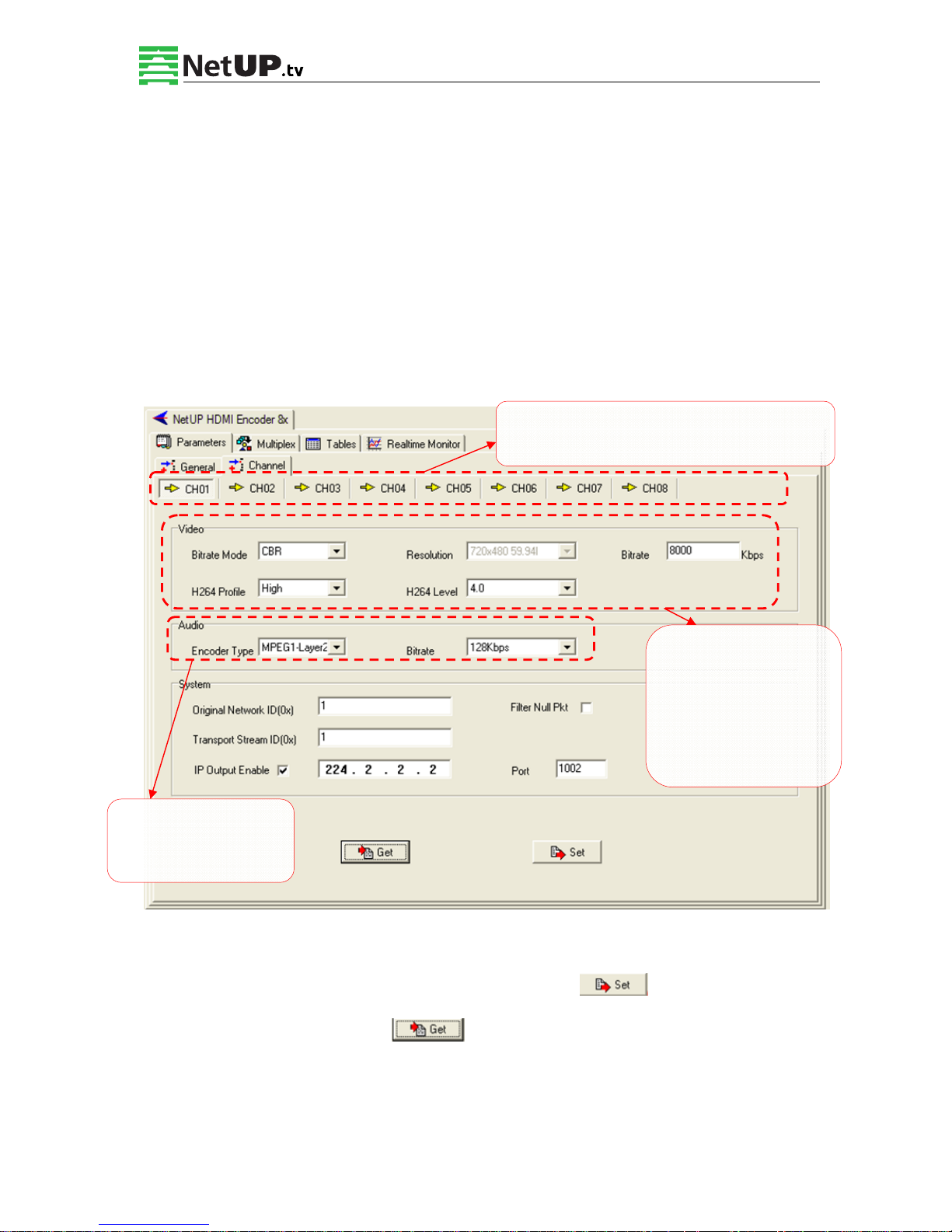
ASI Output Channel
This device supports 1 MPTS (Multiple Programs Transport Stream) and 8 SPTS (Single
Programs Transport Stream) output. User can click to triger a pull-down list to select the
output type.
Output Port
To set the output port by modifying the value in this field.
Original Network ID
This 16-bit field gives the label identifying the network ID of the originating delivery system.
The value ranges from 0 to 0xFFFF.
Transport Stream ID
This is a 16-bit field which serves as a label for identification of this TS from any other
multiplex within the delivery system. The value ranges from 0 to 0xFFFF.
Output Bit Rate (Mbps)
This includes the effective bit-rate of encoding channel 1-8, the effective bit-rate from ASI
input and the bit-rate of stuffed null packets.
UDP Stream TS Package
Users can set the amount of TS packages here.
NIT Insertion
In this field, users can decide whether to effect the NIT (Network Information Table) insertion
function.
Page 32
NetUP HDMI Encoder 8x User’s Manual
30 / 44
Addr: 119311, Russia, Moscow, Ulofa Palme bldg.1, sect 7 Web: http://netup.tv
SDT Insertion
In this field, users can decide whether to effect the SDT insertion function.
MPTS Filter Null Packet
If this function is effected, then the null packets in IP output stream will be filtered.
PSI/SI Editor
This button will trigger the PSI/SI Editor for some users’ advanced usage. For more detail,
please refer to the manual of PSI/SI.
4.3.1.2 Video Parameters (Parameters->Channel->CH0X)
If any parameter is modified, it is supposed to click Set to make the modified
parameters activate and click Get to read and effect the current device’s activating
parameters.
Input channel selection area. The interface and
setting principle of each channel are the same.
Audio Config Area
For manually configuring
audio
q
uality.
Video Config Area:
For manually configuring
video quality, except
resolution, which
automatically is set to the
resolution of source
Page 33
NetUP HDMI Encoder 8x User’s Manual
31 / 44
Addr: 119311, Russia, Moscow, Ulofa Palme bldg.1, sect 7 Web: http://netup.tv
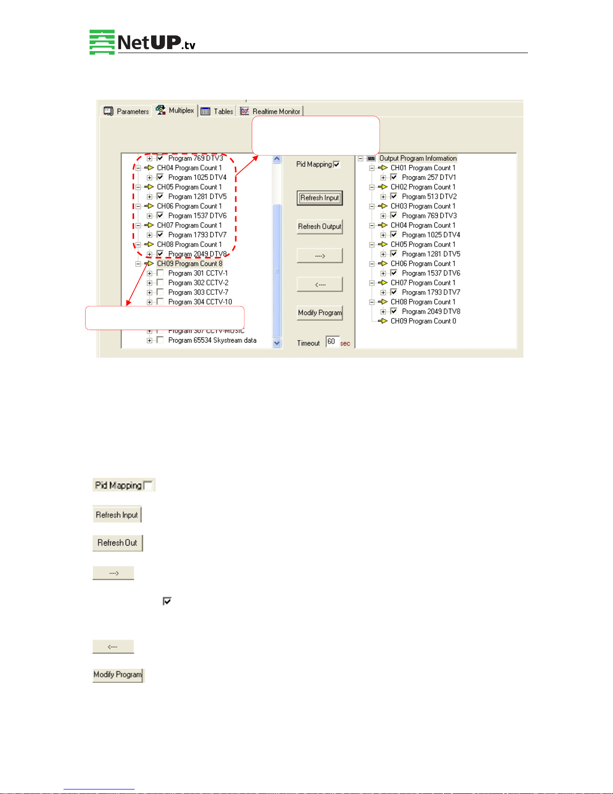
4.3.2 Multiplexing
The programs in the left column represent all input programs and which port they come from,
while the programs in the right column represent the output programs and from which port they
are from. User can parse the programs of each channel and multiplex those programs to the
output. Moreover, user can modify the output programs’ Program Name, PMT, PCR, video,
audio PID.
: Check this box the set the PID Mapping
: To refresh the inputting terminal and get the inputting information
: To refresh the outputting terminal and get the outputting information
: Multiplex the input programs to the output channels after selecting the target
program with . The system will automatically allot the program to the relevant output
channel.
: Cancel the multiplexed programs.
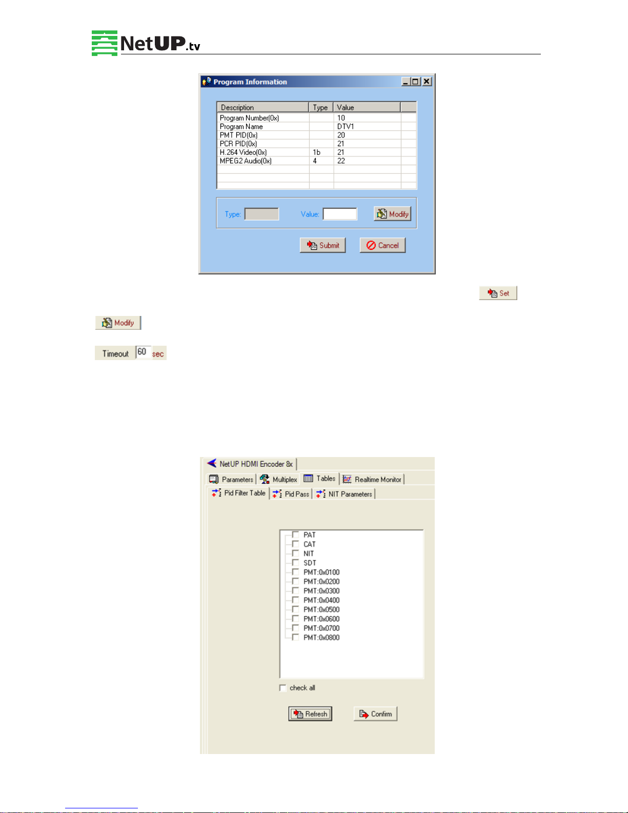
: To modify the output programs’ Program Name, PMT, PCR, video, or audio PID
as needed. To modify program information, user can select the target program in output part
first and click this button to pop up a dialog box as below:
CH01-CH08: The 8 HDMI
Encoding Channels
CH09: The 1 ASI Input Channel
Page 34
NetUP HDMI Encoder 8x User’s Manual
32 / 44
Addr: 119311, Russia, Moscow, Ulofa Palme bldg.1, sect 7 Web: http://netup.tv
Select the target item and input the new value in the box below, then click and
to effect the modification.
: The parsing overtime value
4.3.3 Tables
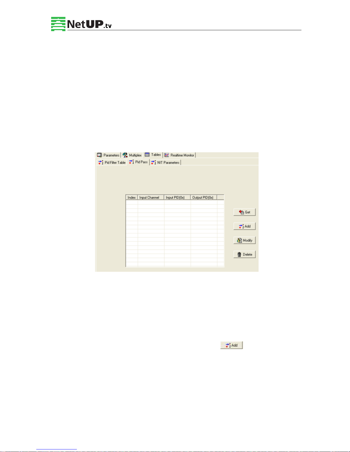
4.3.3.1 PID Filter Table
Page 35
NetUP HDMI Encoder 8x User’s Manual
33 / 44
Addr: 119311, Russia, Moscow, Ulofa Palme bldg.1, sect 7 Web: http://netup.tv
Users can operate PID filter in this table by checking the check boxes of corresponding items
and click CONFIRM to effect.
Refresh: getting PID filter table from the device
Setting: submitting the PID filter table to the device
Check All: selecting all the selections of the list
After user selects one PID in the table, then the corresponding output PSI/SI table will not be
sent to the output stream.
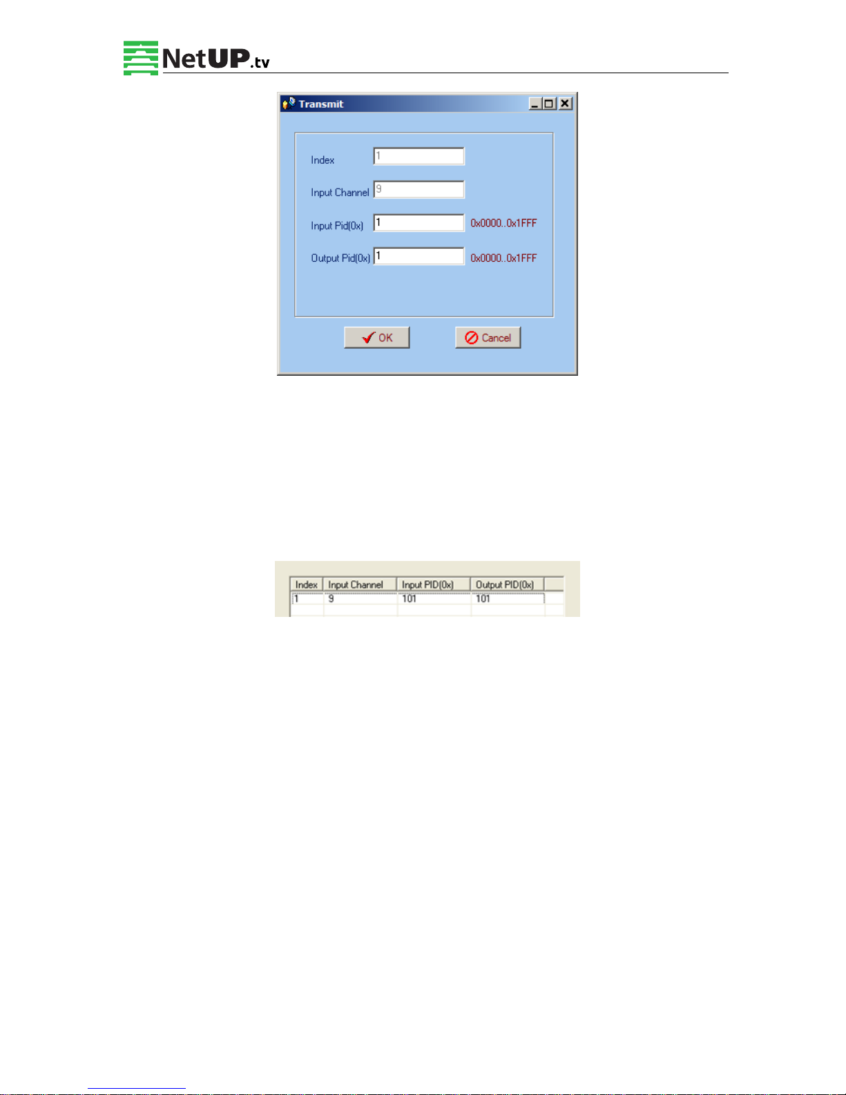
4.3.3.2 PID Pass
User can decide to bypass the inputting PID as needed in this interface.
In some occasions, there are some PIDs which won’t belong to any program, such as EPG, NIT
tables, and so on, but user just wants to pass them through the multiplexing module without
changing anything. This is the main purpose of this function.
The display will show as below when user clicks “Add” button.
Page 36
NetUP HDMI Encoder 8x User’s Manual
34 / 44
Addr: 119311, Russia, Moscow, Ulofa Palme bldg.1, sect 7 Web: http://netup.tv
Input PID and Output PID
The Old (Input) PID is the PID number in the TS from given Port. The correspondent New
(output) PID number could be same as input PID number while it could be different if a PID
remapping is needed.
Modify the data as needed and click OK to confirm. The PID then will be bypassed and listed
in the table as below.
User can also modify or delete the added PID through the corresponding buttons at right.
4.3.3.3 NIT Parameters
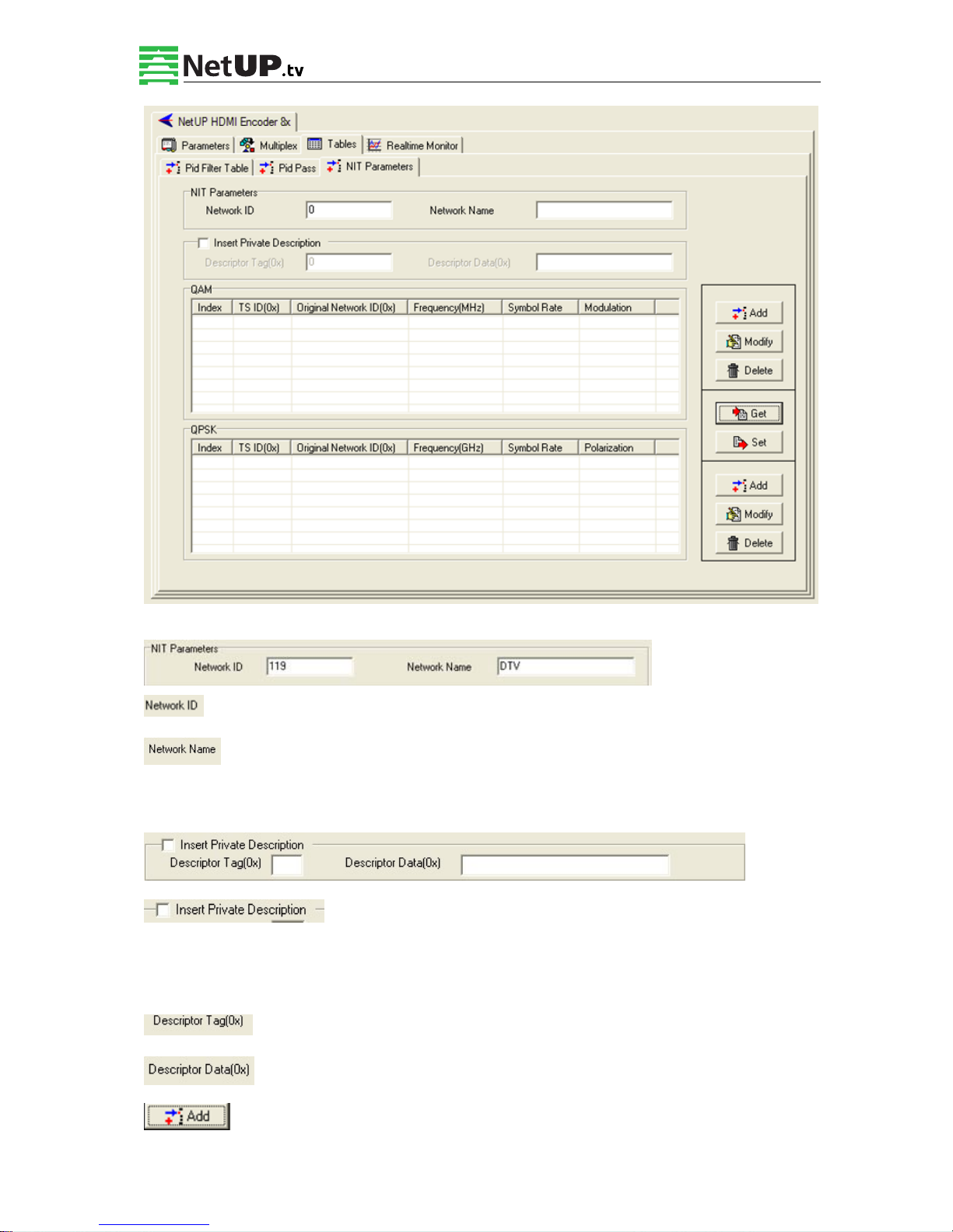
NIT: Network Information Table.
NIT table is a very important table for describing the network and TS. Users can set the parameters of the
output NIT table.
Page 37
NetUP HDMI Encoder 8x User’s Manual
35 / 44
Addr: 119311, Russia, Moscow, Ulofa Palme bldg.1, sect 7 Web: http://netup.tv
:The parameter describes the output TS’s network ID
:The parameter describes the output TS’s network name.
Insertion private description
:This checkbox will allow user to insert the private descriptor into the
output TS. The private descriptor includes two parts. One is descriptor tag, and the other is
descriptor information.
:The Descriptor Tag is an 8-bit field which identifies each descriptor.
:The Descriptor Data is the detailed information of the private description.
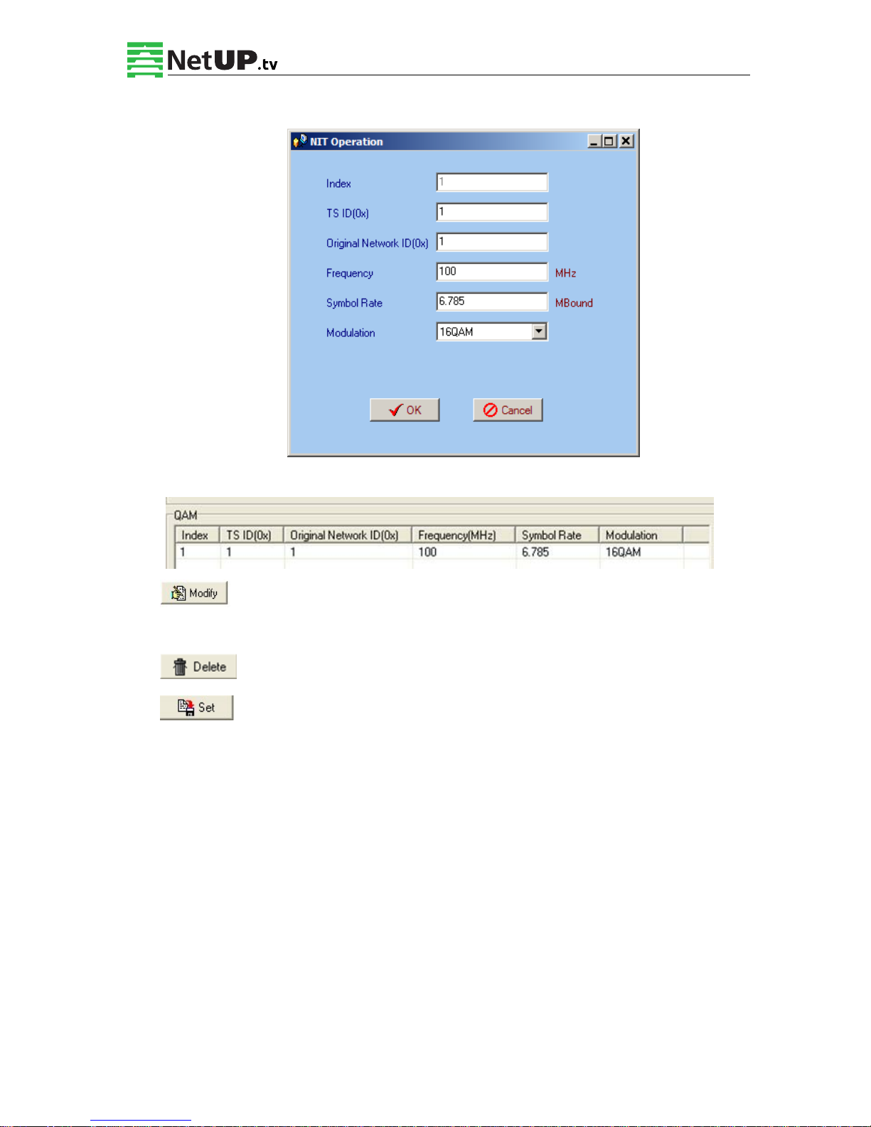
:Users can add the cable transmission descriptor in this Add button, and it will pop
Page 38
NetUP HDMI Encoder 8x User’s Manual
36 / 44
Addr: 119311, Russia, Moscow, Ulofa Palme bldg.1, sect 7 Web: http://netup.tv
up the following dialogue box, say, the added descriptor is apply for the DVB-C network.
The interface will show as below after the NIT parameters being added:
:The “Modify” button will trigger a modify window and allow user to modify
the selected items in the NIT.
:The “Delete” button will remove the selected items in the NIT.
:The set “Button” will send the NIT to the chosen output Port.
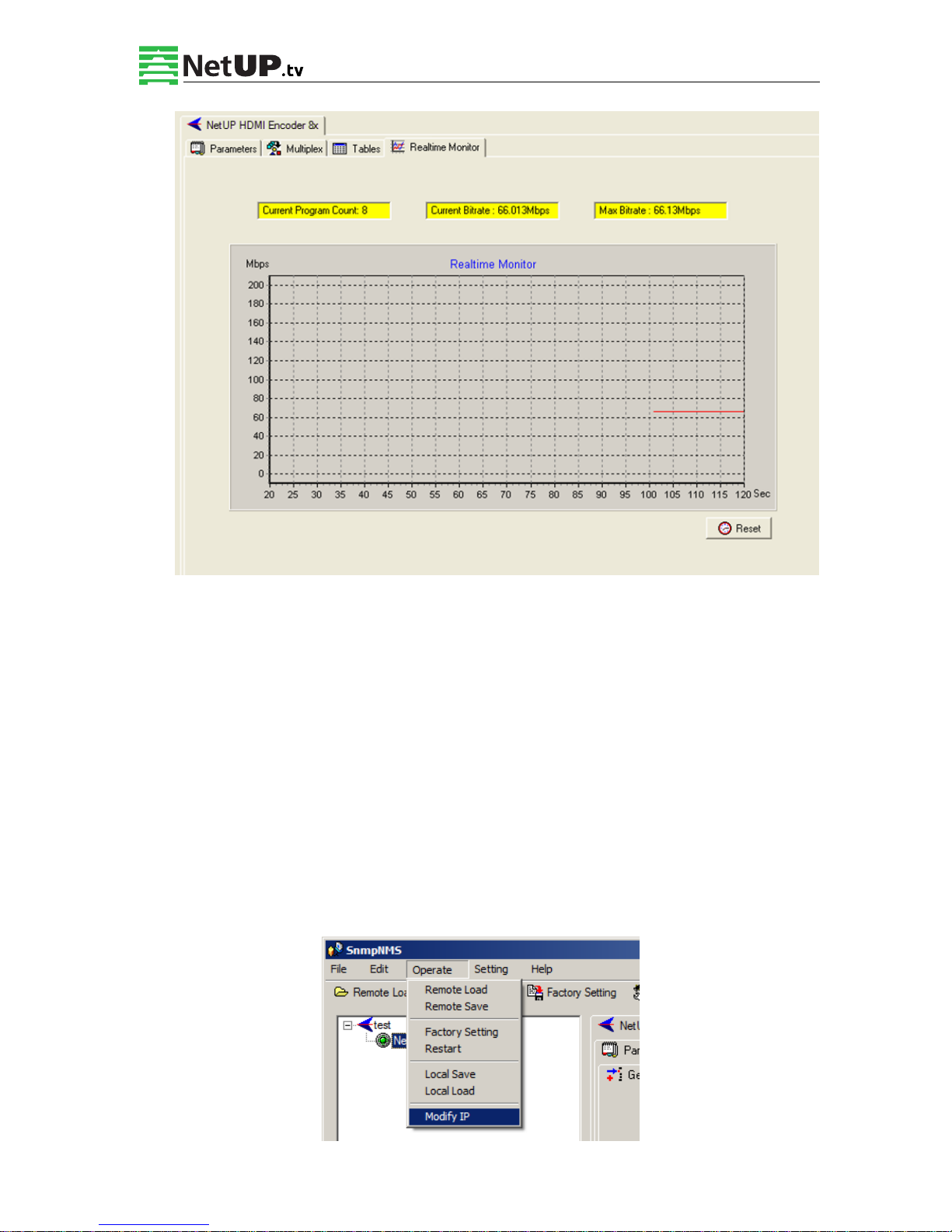
4.3.4 Real-time Monitor
There will be a real-time bit rate chart generating in the monitor for users to check the bit rate
information.
Page 39
NetUP HDMI Encoder 8x User’s Manual
37 / 44
Addr: 119311, Russia, Moscow, Ulofa Palme bldg.1, sect 7 Web: http://netup.tv
4.4 Other Settings
4.4.1 Difference between Set and Remote Save
In many cases during the configuration of parameters in NMS, users save the modified
configuration by clicking “Set”, in which way the configuration can only be saved temporarily
and will restore the last saved configuration if the device reboots. To save the configuration
permanently, it is required to operate through “Remote Save” on the toolbar explained in 4.2.7.
This is the difference between “Set” and “Remote Save”.
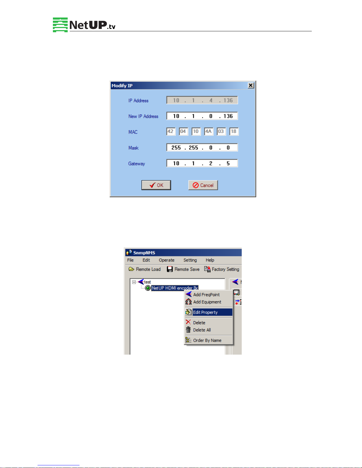
4.4.2 IP Modification
Page 40
NetUP HDMI Encoder 8x User’s Manual
38 / 44
Addr: 119311, Russia, Moscow, Ulofa Palme bldg.1, sect 7 Web: http://netup.tv
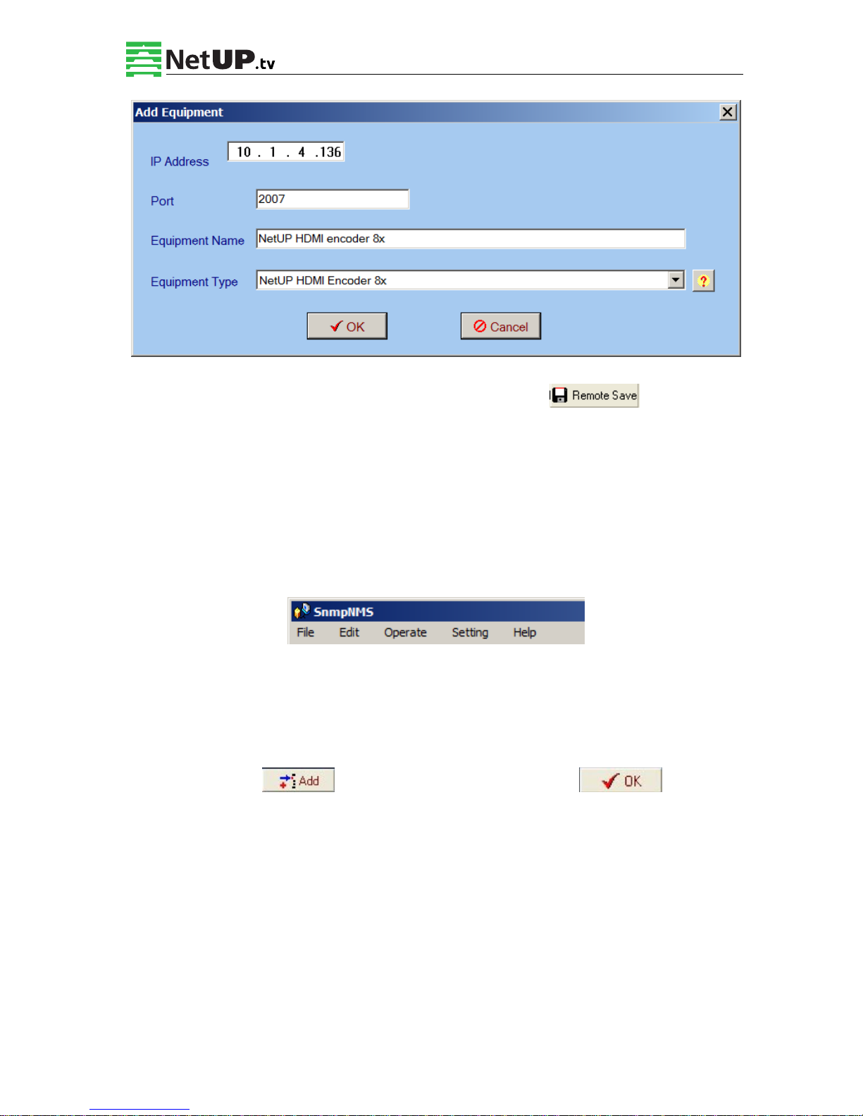
Users can click Operate and select Modify IP in the drop-down list, and a dialog box presents
itself as shown below. Users input the new NMS IP Address for the device and click OK button
to confirm.
Users can then note the indicator light turns red, which signifies the equipment has
disconnected. Users then can refer to below prompts to edit the property by inputting the new
IP to re-connect the equipment.
Input the new IP Address in the box and click OK button, then the device will be connected
again.
Page 41
NetUP HDMI Encoder 8x User’s Manual
39 / 44
Addr: 119311, Russia, Moscow, Ulofa Palme bldg.1, sect 7 Web: http://netup.tv
After finishing all the parameters setting, user should click button on the
toolbar to save the modifications to the device’s flash.
4.4.3 User Add
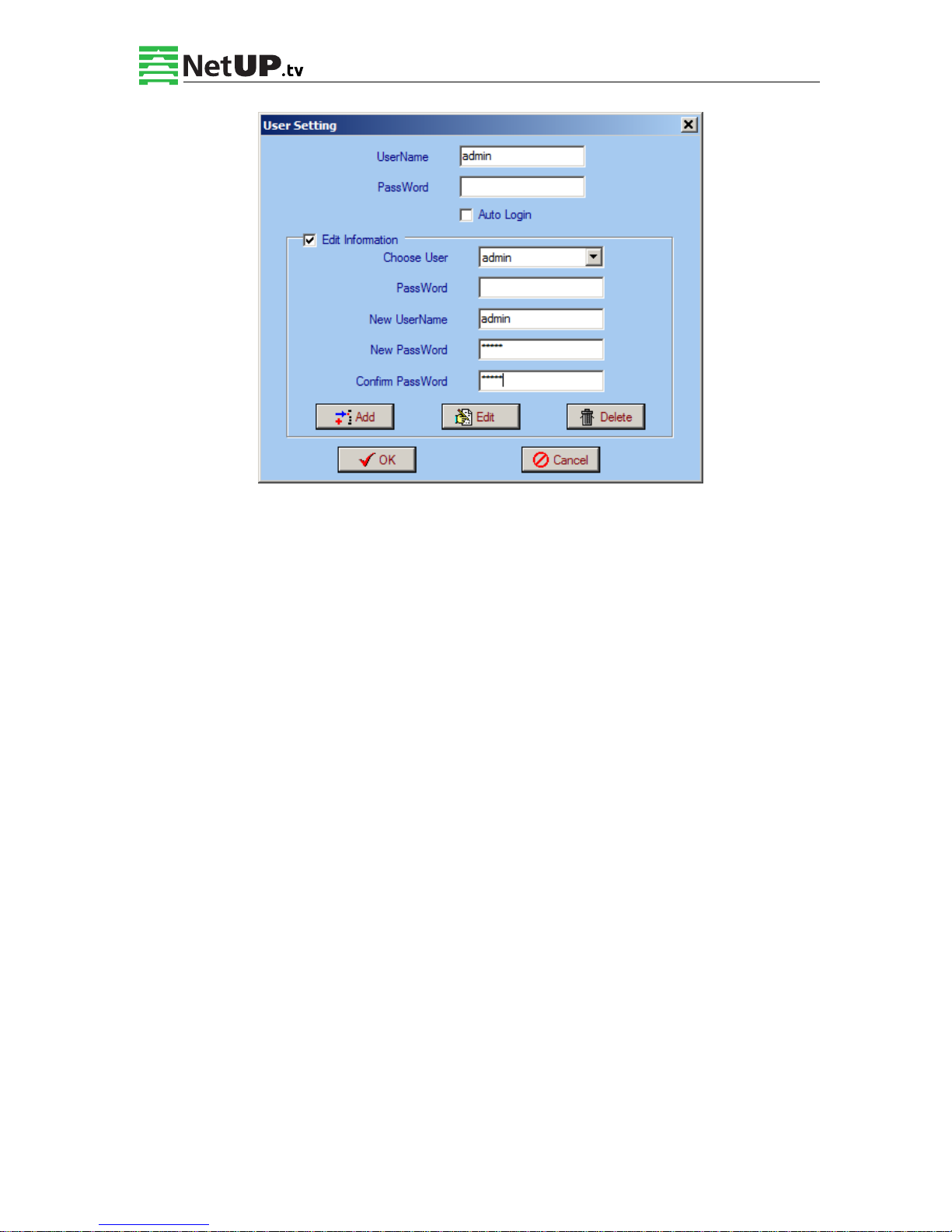
When logging in, user will note that the default user name is admin and no password. User can
add users and passwords as needed.
User clicking “Setting” in the menu bar and selecting “User Setting” in the pull-down list, the
below dialog box will pop out as shown below. Select the “Edit Information” by marking the
check box with “√”, user can input the new username and new password as prompts below. It
is required to click to add the new user and then click to save the
new setting.
Page 42
NetUP HDMI Encoder 8x User’s Manual
40 / 44
Addr: 119311, Russia, Moscow, Ulofa Palme bldg.1, sect 7 Web: http://netup.tv
Page 43

NetUP HDMI Encoder 8x User’s Manual
41 / 44
Addr: 119311, Russia, Moscow, Ulofa Palme bldg.1, sect 7 Web: http://netup.tv
Chapter 5 Troubleshooting
Precautions:
Install the device at a place with average temperature between 0 to 45 °C
Provide good ventilation for the heat-sink on the rear panel and other heat-sink bores if
necessary
Check that the input AC is in the power supply’s working range and that the commutation
is correct before switching the device on
Check if the RF output level varies within tolerant range if it is necessary
Check that all the signal cables are connected properly
Frequent switch on/off of the device is prohibited; the interval between switching the
device on/off must be greater than 10 seconds.
Unplug the power cord to shut down the device when:
The power cord or socket is damaged
Any liquid flowed into the device
Any stuff causes short circuit
Device is in damp environment
Device suffered from physical damage
Longtime idle
After switching on and restoring to factory setting, device still cannot work properly
Maintenance needed
Page 44

NetUP HDMI Encoder 8x User’s Manual
42 / 44
Addr: 119311, Russia, Moscow, Ulofa Palme bldg.1, sect 7 Web: http://netup.tv
Chapter 6 Packing list
NetUP HDMI Encoder 8x 1pcs
User’s manual 1pcs
HDMI cable 8pcs
ASI cable 1pcs
Power cord 1pcs
 Loading...