


Interface Module
UK
User Guide
EIM2000-12
12-Port E1 Inverse Multiplexer
and
EIM2000-24
24-Port E1 Inverse Multiplexer
210-0000054 rev02 EIM2000 User Guide Page 1 of 20
http://www.nettonet.com
contact@nettonet.com
© Copyright 2003 Net to Net Technologies, Inc.
™ The Net to Net Logo is a trademark of Net to Net Technologies, Inc.
Worldwide Headquarters
Net to Net Technologies
112 Corporate Drive
Portsmouth, NH 03801
USA
1 (877) 638-2638
EMEA Headquarters
Net to Net Technologies
Victoria House 19 Park Way
Newbury Berkshire RG14 1EE
44 (0) 1635-570950

Contents
1.0 INSTALLATION
1.1 Unpack and Inspect the EIM2000
1.2 Verify EIM2000 Switch Settings
1.3 Install the EIM2000 in an IP DSLAM Chassis
1.4 Connect the E1 Line(s)
1.5 LED Indications
2.0 E1 PARAMETERS
2.1 Parameter Defaults
2.2 Clock Source
2.3 Frame Type
2.4 Line Code
2.5 Speed
3.0 ADDITIONAL INFORMATION
3.1 Configuration and Management
3.2 Data Storage
3.3 European Regulatory Compliance
1.2.1 Switch 2
1.2.2 Switch 3
1.3.1 Align the EIM2000 with the IP DSLAM Slot Module Guides
1.3.2 Slide the EIM2000 Firmly into the Chassis
1.3.3 Verify that the EIM2000 is Receiving Power
1.3.4 Secure the EIM2000 in the IP DSLAM Chassis
1.4.1 Local Connection
1.4.1.1 Select the Appropriate RJ21 Connector(s)
1.4.1.2 Detach the Velcro Strap and Position the E1 Cable RJ21 Connector(s)
1.4.1.3 Secure the Connector(s)
1.4.1.4 RJ21 Port Pinouts
1.4.2 Remote Connection
1.4.2.1 Loop Bonded Connection
1.4.2.2 Single Line E1 Connection
1.4.3 Verify the Connection
2.2.1 Local (default-provider mode)
2.2.2 Loop (default-subscriber mode)
2.3.1 Cyclic Redundancy Check (default)
2.4.1 High Density Binary 3 (default)
2.4.2 Alternate Mark Inversion
210-0000054 rev02 EIM2000 User Guide Page 2 of 20

CAUTION
Net to Net Technologies strongly recommends the use of proper electrostatic discharge (ESD) precautions when
handling this equipment.
1.0 INSTALLATION
1.1 Unpack and Inspect the EIM2000
If there is visible damage, do not attempt to connect the device; contact Customer Support at 1-877638-2638 (1-603-427-0600 for international customers) or support@nettonet.com.
1.2 Verify EIM2000 Switch Settings
NOTE
EIM2000s with printed circuit boards (PCBs) at rev 810-0000AA have eight switch banks. Section 1.2.1 and
1.2.2 below refer to the switch bank labeled "SW 7"; all switches on the other seven switch banks should be in
the default "up" position. PCBs at any rev other than 810-0000AA have only one switch bank.
1.2.1 Switch 2
1.2.2 Switch 3
Switch 3 indicates to the IP DSLAM's MUM whether the EIM2000 will be acting as an E1
provider or an E1 subscriber. Default, in the UP position, dictates that the EIM2000 will be
acting as a provider. In most cases, this will be the desired setting. The EIM2000 can,
however, be configured to act as an E1 subscriber, if so desired, by placing Switch 3 in the
DOWN position.
The EIM2000 houses a bank of eight [8] switches at the rear of the
module (opposite the faceplate). Switches are numbered from left to
right, 1 - 8. Switches 1 and 4-8 are not used.
CAUTION
Switch 2 indicates, to the IP DSLAM's MUM, that the module is an E1
inverse multiplexer and MUST be in the DOWN position. The EIM2000
will NOT achieve link if Switch 2 is in the UP position.
Provider Mode Subscriber Mode
N
settings will be determined via each port's communication with its respective partner E1 provider.
You will NOT be able to set speed or timing configurations on an EIM2000 in subscriber mode. These
OTE
210-0000054 rev02 EIM2000 User Guide Page 3 of 20

1.3 Install the EIM2000 in an IP DSLAM Chassis
NOTE
There must be a Multiplexer Uplink Module (MUM) with an Uplink Interface Module (UIM) installed in your IP
DSLAM chassis in order for interface modules to operate.
Net to Net Technologies' IP DSLAM interface modules are hot swappable; installing or removing an
interface module while the chassis is powered up does not affect the operational status of other
interface modules within the chassis. The IPD12000 and IPD12000E are fourteen slot chassis; slots
1-12 are reserved for interface modules (such as the EIM2000) and slots 13-14 are reserved for
MUMs. Interface modules may be placed in any order in slots 1-12. The IPD4000 and IPD4000E are
five slot chassis; slots 1-4 are reserved for interface modules and slot 5 is reserved for a MUM.
1.3.1 Align the EIM2000 with the IP DSLAM Slot Module Guides
Slot 1-12 on the IPD12000(E) or slot 1-4 on the IPD4000(E).
210-0000054 rev02 EIM2000 User Guide Page 4 of 20

1.3.2 Slide the EIM2000 Firmly into the Chassis
DO NOT USE EXCESS FORCE.
210-0000054 rev02 EIM2000 User Guide Page 5 of 20

1.3.3 Verify that the EIM2000 is Receiving Power
The PWR (Power) LED on the EIM2000 faceplate will illuminate green.
If your IP DSLAM is not yet powered up,
refer to the IP DSLAM Installation
Instructions for your model at
http://www.nettonet.com/support/docs/#I
.
1.3.4 Secure the EIM2000 in the IP DSLAM Chassis
Tighten the fastening screws on the module faceplate with a Philips or Flathead screwdriver.
210-0000054 rev02 EIM2000 User Guide Page 6 of 20
1.4 Connect the E1 Line(s)
1.4.1 Local Connection
1.4.1.1 Select the Appropriate RJ21 Connector(s)
E1 cables must be connected according to the IP DSLAM slot in which the EIM2000 was
installed. In previous illustrations the EIM2000 was installed in Slot 3, therefore the E1
cable(s) should be plugged into the third RJ21 connector(s) from the right.
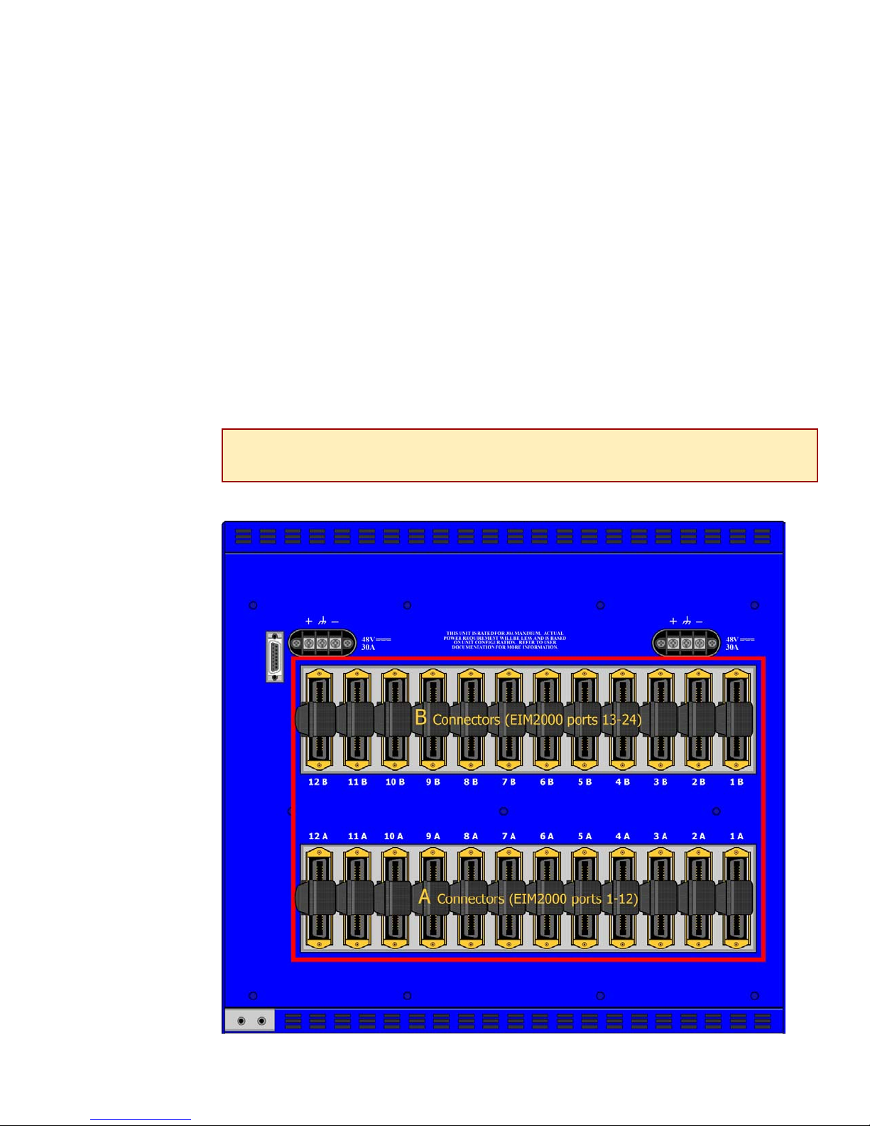
1.4.1.1.1 IPD12000E or IPD4000E
Each interface module slot on the IPD12000E and IPD4000E has two [2]
corresponding RJ21 connectors located on the back of the chassis. The bottom
row of RJ21 connectors (A) on the IPD12000E provides the E1 connection for
EIM2000 ports 1-12 and the top row of RJ21 connectors (B) provides the E1
connection for EIM2000 ports 13-24. On the IPD4000E, the A connectors for each
interface module slot are on the left and the B connectors are on the right.
NOTE
The EIM2000-24 utilizes both rows of RJ21 connectors on the IPD12000E and IPD4000E.
The EIM2000-12 utilizes only the A connectors on the IPD12000E (lower row) and
IPD4000E (left-hand side).
210-0000054 rev02 EIM2000 User Guide Page 7 of 20
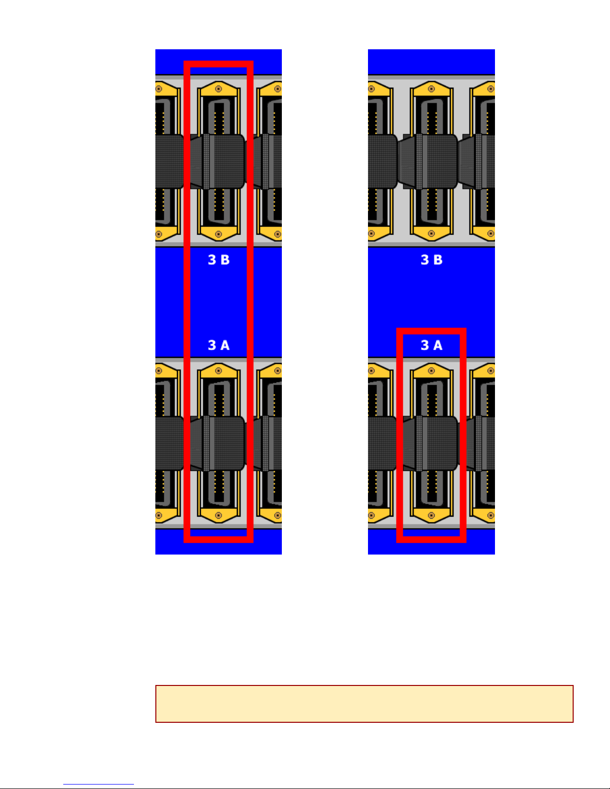
EIM2000-24
For the
EIM2000-24,
you must
connect an
E1 cable to
both the
A and B
Connectors
in order to
utilize
all 24 E1 ports.
EIM2000-12
For the
EIM2000-12,
connect an E1
cable
to the A
Connector
only; the B
Connector
has no function
for the
EIM2000-12.
IPD12000E IPD12000E
1.4.1.1.2 IPD12000 or IPD4000
Each interface module slot on the IPD12000 and IPD4000 has one corresponding
RJ21 port located on the back of the chassis which will connect EIM2000 E1 ports
1-12.
NOTE
Although the EIM2000-24 can function in an IPD12000 or IPD4000, you will not be able to
utilize ports 13-24; the IPD12000 and IPD4000 do not have the second row of B
connectors necessary to support additional E1 ports.
210-0000054 rev02 EIM2000 User Guide Page 8 of 20

EIM2000-24 and EIM2000-12
There is only one RJ21 port, for each module
slot, to which an E1 connection can be made.
This connection will support E1 ports 1-12
on both the EIM2000-12 and the EIM2000-24;
you will not be able to utilize ports 13-24
on an EIM2000-24 installed in an IPD12000 or
IPD4000.
210-0000054 rev02 EIM2000 User Guide Page 9 of 20

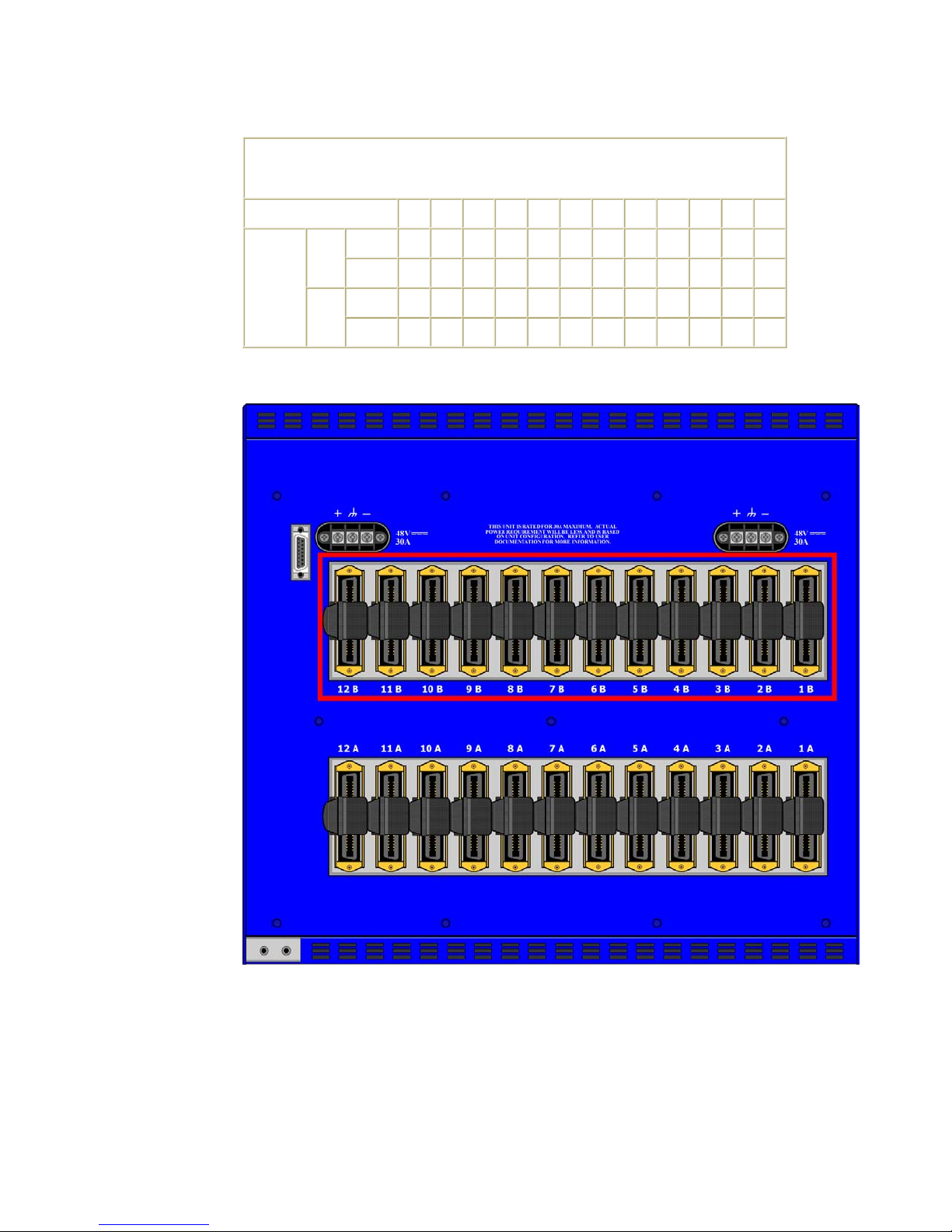
1.4.1.2 Detach the Velcro Strap and Position the E1 Cable RJ21 Connector(s)
1.4.1.2.1 IPD12000 and IPD12000E
Detach the Velcro strap and pull it open to the right, leaving it looped under the
connector frame on the right side. Slide the RJ21 connector of your E1 cable
underneath the Velcro and press it firmly into the RJ21 connector on the chassis.
1.4.1.2.2 IPD4000 and IPD4000E
On the IPD4000 and IPD4000E the RJ21 connectors attach horizontally with the
E1 cable trailing off to the left. Detach the Velcro strap and pull it open and
downward, leaving it looped under the bottom edge of the connector frame. Slide
the RJ21 connector of your E1 cable underneath the Velcro, from the left, and
press it firmly into the RJ21 connector on the chassis.
1.4.1.3 Secure the Connector(s)
1.4.1.3.1 IPD12000 and IPD12000E
Screw the top of the T1 cable connector into the jack screw at the top of the RJ21
connector frame on the chassis. If you are using a 120° or 180° cable, both the
top and the bottom of the cable connector should be secured to the RJ21
connector frame on the chassis.
NOTE
The RJ21 connector cannot be screwed into the connector frame on the IPD12000. An E1
connection on the IPD12000 can only be secured via the Velcro strap.
210-0000054 rev02 EIM2000 User Guide Page 10 of 20

Pull the Velcro strap to the right, making sure that it is snug against the connector,
and then pull the strap back across to the left, sticking it to itself across the top of
the connector. Tuck the tab at the end of the strap down to the left of the
connector frame so it is out of the way of other connections.
1.4.1.3.2 IPD4000 and IPD4000E
Screw the right side of the E1 cable connector into the jack screw at the right side
of the RJ21 connector frame on the chassis. If you are using a 120° or 180°
cable, both the right and left sides of the cable connector should be secured to the
RJ21 connector frame on the chassis.
NOTE
The RJ21 connector cannot be screwed into the connector frame on the IPD4000. An E1
connection on the IPD4000 can only be secured via the Velcro strap.
Pull the Velcro strap downward, making sure that it is snug against the connector,
and then pull the strap up and over the RJ21 connector, sticking it to itself across
the top of the connector. Tuck the tab at the end of the Velcro strap above the
connector frame towards the chassis so it is out of the way of other connections.
210-0000054 rev02 EIM2000 User Guide Page 11 of 20

1.4.1.4 RJ21 Port Pinouts
1.4.1.4.1 RJ21 Pins
EIM2000
RJ21
Port
E1
RJ21
Connector
210-0000054 rev02 EIM2000 User Guide Page 12 of 20

1.4.1.4.2 A Connector Pinout
A CONNECTORS
(IPD12000E bottom row, IPD4000E left side, IPD12000 and IPD4000)
EIM2000 E1 PORTS 1 2 3 4 5 6 7 8 9 10 11 12
Ring 14 15 16 17 18 19 20 21 22 23 24 25
TX
RJ21
PINS
(pins 13 and 38 are not used)
Tip 39 40 41 42 43 44 45 46 47 48 49 50
Ring 1 2 3 4 5 6 7 8 9 10 11 12
RX
Tip 26 27 28 29 30 31 32 33 34 35 36 37
IPD12000E
210-0000054 rev02 EIM2000 User Guide Page 13 of 20
1.4.1.4.3 B Connector Pinout
B CONNECTORS
(IPD12000E top row and IPD4000E right side)
EIM2000 E1 PORTS 13 14 15 16 17 18 19 20 21 22 23 24
Ring 14 15 16 17 18 19 20 21 22 23 24 25
TX
RJ21
PINS
(pins 13 and 38 are not used)
Tip 39 40 41 42 43 44 45 46 47 48 49 50
Ring 1 2 3 4 5 6 7 8 9 10 11 12
RX
Tip 26 27 28 29 30 31 32 33 34 35 36 37
IPD12000E
1.4.2 Remote Connection
The EIM2000 is capable of supporting both single-line connections and multiple-line loop
bonded connections, as well as any combination of the two. If the distance(s) between the
EIM2000 and any of the remote E1 equipment is greater than 6,000 feet, the line(s) may
require an E1 repeater.
210-0000054 rev02 EIM2000 User Guide Page 14 of 20

1.4.2.1 Loop Bonded Connection
Using multiple E1 lines for one network connection (loop bonding) will net speed and
data passing capability equal to the cumulative total of the individual single-line
connections. Multiple E1 lines used for one connection can also be considered backup
for each other should one or more of the lines become disabled. Any of the ports on the
EIM2000-12 or EIM2000-24 can be bonded together; it is not necessary for them to be
consecutive.
AUTION
C
All E1 ports intended for a loop bonded connection MUST be identically configured PRIOR to
connection. See Net to Net's NMS Management User Guide and/or CLI Management User
Guide for configuration instructions. If default settings are to be used for bonded ports, then
prior configuration is not necessary and you may proceed with installation.
The E1 equipment to which an EIM2000 is connected must also be E1 loop bonding
capable in order for the EIM2000 to establish a loop bonded connection. Refer to Net to
Net's E1 Loop Bonding Product to Product Feature Compatibility document at
http://www.nettonet.com/support/docs/230-0000035 .
1.4.2.2 Single Line E1 Connection
A single line connection can be established between the EIM2000 and any of Net to
Net's E1 modems.
1.4.3 Verify the Connection
For each port being connected to a remote E1 modem, verify that the E1 link has been
established.
The E1 LK LED of connected ports will illuminate green
to indicate a connection has been made.
Link up should occur within 20 seconds
depending on the quality, gauge and distance
of the copper cable(s).
210-0000054 rev02 EIM2000 User Guide Page 15 of 20

1.5 LED Indications
LED
PWR (Power) solid green EIM2000 is operational If the Power LED is not illuminated, it is
State Indication Additional Information
unlikely the EIM2000 is receiving power and
none of the LEDs will be illuminated.
LK (Link) pulsing
green
solid green problematic E1 connection A connection exists but there is indication of a
no
illumination
RX (Reception) flashing
amber
solid amber heavy Rx traffic The port is receiving unusually large amounts
no
illumination
E1 connection is established and
active
Loss of Synchronization (LOS)
The incoming connection to the E1
port has been lost; no data is being
received.
E1 activity The port is receiving data from the remote E1
no activity A link may exist but the port is not receiving
The E1 link is operational and traffic is flowing.
problem with the E1 line.
If the outgoing connection from the E1 port has
also been lost then the remote E1 modem will
have LOS as well.
modem.
of data from the remote E1 modem.
any data from the remote E1 modem.
TX
(Transmission)
210-0000054 rev02 EIM2000 User Guide Page 16 of 20
flashing
amber
solid amber heavy Tx traffic The port is transmitting unusually large
no
illumination
E1 activity The port is transmitting data to the remote E1
modem.
amounts of data to the remote E1 modem.
no activity A link may exist but the port is not transmitting
any data to the remote E1 modem.

AL (Alarm) no
illumination
solid amber Remote Alarm Indication (RAI)
E1 is operational An established E1 link has no alarm indications
and is operational UNLESS the LK LED remains
unlit as well, in which case the E1 port has
LOS.
The remote E1 modem has lost its incoming
An outgoing connection has been
lost; the remote E1 modem is not
receiving any data from the E1 port.
connection and has LOS.
pulsing
amber
Alarm Indication Signal (AIS)
An indirect connection has been lost;
the E1 port may no longer be
receiving data from the remote E1
modem.
The remote E1 modem has lost a connection
with an intermediate device and has LOS or
RAI.
(A pulsing LED blinks steadily at a rate of once per second. A flashing LED blinks at a more rapid, less constant rate.)
2.0 E1 PARAMETERS
Parameters common to all of Net to Net's interface modules are defined in Net to Net's management user
guides; refer to the NMS Management User Guide ( http://www.nettonet.com/support/docs/210-
0000048 ) and/or the CLI Management User Guide ( http://www.nettonet.com/support/docs/2100000052 ). Parameters specific to the EIM2000 are outlined below.
2.1 Parameter Defaults
No configuration is necessary for the EIM2000 to operate at default settings.
Parameter Default
Clock Source
Flood Uplink
Frame Type Cyclic Redundancy Check (CRC)
IP Range 1 0.0.0.0 - 255.255.255.255
IP Range 2 0.0.0.0 - 0.0.0.0
Line Code High Density Binary 3 (HDB3)
Priority 0
Protocol ALL
Speed (Single Line) 1,984 kbps
VLAN 0 - 0
VLAN Back-bone 0
Local - provider mode
Loop - subscriber mode
210-0000054 rev02 EIM2000 User Guide Page 17 of 20

2.2 Clock Source
Clock source refers to the timing origination for E1 transmission links.
2.2.1 Local (default-provider mode)
Timing is derived from an oscillator on board the EIM2000.
2.2.2 Loop (default-subscriber mode)
Timing is derives from an intermediate device on the E1 line.
NOTE
Local timing is the default for an EIM2000 in E1 provider mode. Default for an EIM2000 in subscriber mode is
Loop and cannot be modified.
2.3 Frame Type
Frame type is the E1 data encapsulation method. A frame consists of 248 bits (8-bit samples of
each of the 31 E1 data channels plus a synchronization bit) transmitted at a rate of 8,000 frames
per second (1,984 kbps) across the E1 line. EIM2000 frame type configuration options are Cyclic
Redundancy Check or No Cyclic Redundancy Check.
2.3.1 Cyclic Redundancy Check (default)
Cyclic Redundancy Check (CRC) detects line errors and scrutinizes data integrity across the E1
line by appending a CRC character to the end of each data block. The character is a
hexadecimal value calculated from the contents of the data block; if a different value is
calculated at the receiving end than was appended at the originatation point, retransmission is
requested.
2.4 Line Code
Line code is the E1 mode of transmission. The two line code options for the EIM2000 both fall within
the International Telecommunication Union - Telecommunication Standardization Sector (ITU-T)
G.703 Standards for Transmission Facilities.
2.4.1 High Density Binary 3 (default)
High Density Binary 3 (HDB3) line encoding uses bipolar violations to guarantee the presence
of pulses in the E1 line thereby helping to prevent loss of synchronization between the
EIM2000 and remote E1 equipment. HDB3 accommodates the minimum ones density
requirement in the European public network.
2.4.2 Alternate Mark Inversion
Alternate Mark Inversion (AMI) alternates positive and negative pulses across the E1 line.
Although AMI links typically encounter long strings of zeros which can potentially cause loss of
synchronization between E1 units, Net to Net Technologies' E1 products meet the European
minimum ones density requirement internally such that, even with AMI, loss of synchronization
is prevented between the EIM2000 and remote E1 equipment, just as it is with HDB3.
210-0000054 rev02 EIM2000 User Guide Page 18 of 20

2.5 Speed
All E1 lines consist of 31 channels (timeslots) that continually run at 64 kbps for a collective
bandwidth of 1,984 kbps. Timeslot configuration dictates how many of the channels for each port
will actually receive data. Ports configured to operate as fractional E1 lines require contiguous
timeslots as indicated in the chart below.
Single Line T1 Bandwidth (kbps)
TIMESLOTS 1 - 31 1 - 28 1 - 24 1 - 20 1 - 16 1 - 12 1 - 8 1 - 4
COLLECTIVE
SPEED
1,984 1,792 1,536 1,280 1,024 768 512 256
3.0 ADDITIONAL INFORMATION
3.1 Configuration and Management
Default bandwidth utilizes
all 31 timeslots for a
collective speed of 1,984 kbps.
Once the EIM2000 has been installed, all parameter settings are software selectable via Command
Line Interface (CLI), Simple Network Management Protocol (SNMP) and/or Net to Net's Network
Management System (NMS) dependent upon the multiplexer uplink module (MUM) model installed
in your IP DSLAM. Refer to Net to Net's NMS Management User Guide
( http://www.nettonet.com/support/docs/210-0000048 ) and/or CLI Management User Guide
( http://www.nettonet.com/support/docs/210-0000052 ) for further instruction regarding IP DSLAM
management and interface module parameter configuration.
3.2 Data Storage
Upon initial power up of the IP DSLAM, default parameters of the EIM2000 will remain in place
unless changed via NMS, CLI or SNMP. Once changed, new configurations will automatically be
recorded in both the Random Access Memory (RAM) of the EIM2000 and the Non-Volatile Random
Access Memory (NVRAM) of the MUM. While data stored in EIM2000 RAM will be erased if the
module is removed from the IP DSLAM, or the IP DSLAM loses power, interface module data stored
within MUM NVRAM will remain intact (even if the chassis loses power) unless deliberately cleared or
reconfigured.
3.3 European Regulatory Compliance
This Class A product complies with European Norm EN55022.
Warning: In a domestic environment this product may cause radio interference in which case the
user may be required to take adequate measures to correct the situation.
210-0000054 rev02 EIM2000 User Guide Page 19 of 20

© Copyright 2003 Net to Net Technologies, Inc.
™ The Net to Net Logo is a trademark of Net to Net Technologies, Inc.
Worldwide Headquarters
Net to Net Technologies
112 Corporate Drive
Portsmouth, NH 03801
USA
+1 877-638-2638
210-0000054 rev02 EIM2000 User Guide Page 20 of 20
http://www.NetToNet.com/
Contact@NetToNet.com
EMEA Headquarters
Net to Net Technologies
Victoria House 19 Park Way
Newbury Berkshire RG14 1EE
UK
+44 (0) 1635 570950
 Loading...